EP3900505B1 - Dispositif de commande pour véhicule de travail à déplacement automatique - Google Patents
Dispositif de commande pour véhicule de travail à déplacement automatique Download PDFInfo
- Publication number
- EP3900505B1 EP3900505B1 EP19897852.0A EP19897852A EP3900505B1 EP 3900505 B1 EP3900505 B1 EP 3900505B1 EP 19897852 A EP19897852 A EP 19897852A EP 3900505 B1 EP3900505 B1 EP 3900505B1
- Authority
- EP
- European Patent Office
- Prior art keywords
- vehicle
- estimated
- travel
- work
- calculate
- Prior art date
- Legal status (The legal status is an assumption and is not a legal conclusion. Google has not performed a legal analysis and makes no representation as to the accuracy of the status listed.)
- Active
Links
Images


Classifications
-
- A—HUMAN NECESSITIES
- A01—AGRICULTURE; FORESTRY; ANIMAL HUSBANDRY; HUNTING; TRAPPING; FISHING
- A01B—SOIL WORKING IN AGRICULTURE OR FORESTRY; PARTS, DETAILS, OR ACCESSORIES OF AGRICULTURAL MACHINES OR IMPLEMENTS, IN GENERAL
- A01B69/00—Steering of agricultural machines or implements; Guiding agricultural machines or implements on a desired track
- A01B69/007—Steering or guiding of agricultural vehicles, e.g. steering of the tractor to keep the plough in the furrow
- A01B69/008—Steering or guiding of agricultural vehicles, e.g. steering of the tractor to keep the plough in the furrow automatic
-
- A—HUMAN NECESSITIES
- A01—AGRICULTURE; FORESTRY; ANIMAL HUSBANDRY; HUNTING; TRAPPING; FISHING
- A01D—HARVESTING; MOWING
- A01D41/00—Combines, i.e. harvesters or mowers combined with threshing devices
- A01D41/12—Details of combines
- A01D41/127—Control or measuring arrangements specially adapted for combines
- A01D41/1278—Control or measuring arrangements specially adapted for combines for automatic steering
-
- G—PHYSICS
- G05—CONTROLLING; REGULATING
- G05D—SYSTEMS FOR CONTROLLING OR REGULATING NON-ELECTRIC VARIABLES
- G05D1/00—Control of position, course, altitude or attitude of land, water, air or space vehicles, e.g. using automatic pilots
- G05D1/02—Control of position or course in two dimensions
- G05D1/021—Control of position or course in two dimensions specially adapted to land vehicles
- G05D1/0212—Control of position or course in two dimensions specially adapted to land vehicles with means for defining a desired trajectory
- G05D1/0219—Control of position or course in two dimensions specially adapted to land vehicles with means for defining a desired trajectory ensuring the processing of the whole working surface
-
- G—PHYSICS
- G05—CONTROLLING; REGULATING
- G05D—SYSTEMS FOR CONTROLLING OR REGULATING NON-ELECTRIC VARIABLES
- G05D1/00—Control of position, course, altitude or attitude of land, water, air or space vehicles, e.g. using automatic pilots
- G05D1/02—Control of position or course in two dimensions
- G05D1/021—Control of position or course in two dimensions specially adapted to land vehicles
- G05D1/0212—Control of position or course in two dimensions specially adapted to land vehicles with means for defining a desired trajectory
- G05D1/0223—Control of position or course in two dimensions specially adapted to land vehicles with means for defining a desired trajectory involving speed control of the vehicle
-
- G—PHYSICS
- G05—CONTROLLING; REGULATING
- G05D—SYSTEMS FOR CONTROLLING OR REGULATING NON-ELECTRIC VARIABLES
- G05D1/00—Control of position, course, altitude or attitude of land, water, air or space vehicles, e.g. using automatic pilots
- G05D1/02—Control of position or course in two dimensions
- G05D1/021—Control of position or course in two dimensions specially adapted to land vehicles
- G05D1/0276—Control of position or course in two dimensions specially adapted to land vehicles using signals provided by a source external to the vehicle
- G05D1/0278—Control of position or course in two dimensions specially adapted to land vehicles using signals provided by a source external to the vehicle using satellite positioning signals, e.g. GPS
-
- G—PHYSICS
- G05—CONTROLLING; REGULATING
- G05D—SYSTEMS FOR CONTROLLING OR REGULATING NON-ELECTRIC VARIABLES
- G05D1/00—Control of position, course, altitude or attitude of land, water, air or space vehicles, e.g. using automatic pilots
- G05D1/20—Control system inputs
- G05D1/24—Arrangements for determining position or orientation
- G05D1/247—Arrangements for determining position or orientation using signals provided by artificial sources external to the vehicle, e.g. navigation beacons
- G05D1/248—Arrangements for determining position or orientation using signals provided by artificial sources external to the vehicle, e.g. navigation beacons generated by satellites, e.g. GPS
-
- G—PHYSICS
- G05—CONTROLLING; REGULATING
- G05D—SYSTEMS FOR CONTROLLING OR REGULATING NON-ELECTRIC VARIABLES
- G05D1/00—Control of position, course, altitude or attitude of land, water, air or space vehicles, e.g. using automatic pilots
- G05D1/60—Intended control result
- G05D1/648—Performing a task within a working area or space, e.g. cleaning
-
- G—PHYSICS
- G05—CONTROLLING; REGULATING
- G05D—SYSTEMS FOR CONTROLLING OR REGULATING NON-ELECTRIC VARIABLES
- G05D1/00—Control of position, course, altitude or attitude of land, water, air or space vehicles, e.g. using automatic pilots
- G05D1/60—Intended control result
- G05D1/65—Following a desired speed profile
-
- B—PERFORMING OPERATIONS; TRANSPORTING
- B62—LAND VEHICLES FOR TRAVELLING OTHERWISE THAN ON RAILS
- B62D—MOTOR VEHICLES; TRAILERS
- B62D15/00—Steering not otherwise provided for
- B62D15/02—Steering position indicators ; Steering position determination; Steering aids
- B62D15/025—Active steering aids, e.g. helping the driver by actively influencing the steering system after environment evaluation
-
- B—PERFORMING OPERATIONS; TRANSPORTING
- B62—LAND VEHICLES FOR TRAVELLING OTHERWISE THAN ON RAILS
- B62D—MOTOR VEHICLES; TRAILERS
- B62D6/00—Arrangements for automatically controlling steering depending on driving conditions sensed and responded to, e.g. control circuits
- B62D6/002—Arrangements for automatically controlling steering depending on driving conditions sensed and responded to, e.g. control circuits computing target steering angles for front or rear wheels
Definitions
- the present invention relates to a control device for a work vehicle configured to travel autonomously along a target travel path.
- JP 2002-182741 discloses an agricultural work vehicle configured to travel autonomously along a preset target travel path.
- the agricultural work vehicle includes a steering mechanism controllable such that a vehicle position calculated with use of a GPS moves to a target point set on a target travel path.
- the steering mechanism is controlled to, in a case involving a larger lateral separation distance between the target travel path and a front portion of the vehicle body, further reduce the distance between the front portion and the target point.
- JP 2016-155491 discloses a work vehicle configured to compute a target steering amount from a positional deviation and directional deviation from a target travel path so that a steering drive signal is outputted on the basis of the target steering amount.
- the target steering amount is computed from a first steering value and a second steering value, the first steering value being computed on the basis of a lateral positional deviation, the second steering value being computed on the basis of a value obtained by adjusting, with use of a weighting factor, a computed value derived from a directional deviation, the weighting factor being intended to reduce the computed value further in a case involving a larger positional deviation.
- Document JP 2018/148858 A describes a work vehicle including: an automatic steering-control part capable of changing over between an automatic-steering on state of causing a travel device to automatically steer a travel machine body such that the travel machine body travels along a target line on the basis of positioning information including position information acquired by a receiver, and an automatic-steering off state of not automatically steering the travel device.
- a changeover operation tool is capable of changing over the automatic steering control part from the automatic-steering off state to the automatic-steering on state on the basis of a manual operation and a reference setup part setting up the target line on a correction position that is calculated on the basis of a value obtained by adding a front-side clearance of the travel machine body to a position of the receiver when it is changed over from the automatic-steering off state to the automatic-steering on state by the changeover operation tool.
- Document JP 5 593606 B describes a travel supporting device wherein two or more correction amounts are computed so that the errors in the lateral direction are reduced between target points on a target track and two or more traveling points on a traveling track on which a vehicle is predicted to travel after the present point, and the correction of the steering state of the vehicle is repeated based on the computed correction amount.
- the steering state of the vehicle is not corrected so that the vehicle is moved straight to the final target point, but it is corrected so that the vehicle is moved in a curved like the traveling track.
- Document JP H06 300580 A describes a control device for tracking vehicle course, wherein deviations between the extending line of the center of a vehicle and on objective course passing through the center of the vehicle are computed at a near watching position and a far watching position.
- An estimated course of the vehicle at the respective watching positions are computed out of steering angle, vehicle speed, and the deviations between the estimated course and the objective course are computed. Based on the computed deviations, it is judged whether the course is a straight line or a curved passage of large curvature, or a steady curved passage.
- a steering angle computing equation selecting means selects a model equation at setting the steering angle. When the model equation is changed from primary steering angle estimating equation to secondary near point estimation equation and this secondary estimation equation is corrected by primary delay correcting value, the vehicle is controlled to slowly approach the objective course.
- Document JP 2016/146061 A1 describes a travelling control device, wherein an image processing part includes: a loss point tracking part for defining a loss point from a photographed image and comparing a change in position of a reference region set on the ground in the photographed image with the position of the loss point to calculate the back- and-forth and left-and-right moving amounts of the vehicle.
- a first correction part for calculating a first correction amount based on the positional shifting amount of the vehicle in the left-and-right direction calculated by the loss point tracking part is provided.
- a second correction part for estimating the current vehicle position information of a past target position outside the visual field of the photographed image to calculate a second correction amount on the basis of the vehicle positional shifting amount from the past target position and a third correction part for specifying a target tracking line by combining position information generated by tracking the target position far by using the luminance distribution information of the photographed image with the position information of the past target position and calculating a third correction amount on the basis of the curvature of the target tracking line are provided.
- the device further includes a target steering angle calculation part for calculating a target steering angle based on the target position, the first correction amount, the second correction amount, and the third correction amount.
- the respective work vehicles of JP 2002-182741 and JP 2016-155491 are each controlled to be steered on the basis of a steering angle calculated at the time of detection of a positional deviation from a target travel path to overcome the positional deviation.
- a steering angle calculated at the time of detection of a positional deviation from a target travel path to overcome the positional deviation.
- the work vehicle will be steered at a small steering angle if the positional deviation is small at that time. This will cause the work vehicle to be steered by an excessively small amount and to thereby be unstable in autonomous travel.
- the control device in order for the vehicle body to be steered autonomously along a target travel path, calculates not the current vehicle position but an estimated vehicle position and controls the steering of the vehicle body on the basis of the estimated vehicle position, the estimated vehicle position being a vehicle position at which the work vehicle will be present after performing predetermined travel from the current vehicle position.
- the control device predicts a vehicle position to serve as a basis for steering control and thereby prevents the vehicle body from being steered by an excessively small amount or an excessively large amount for appropriate autonomous travel.
- a work vehicle may be deviated from its target travel path in the form of a lateral deviation.
- a lateral deviation refers to a positional deviation of the work vehicle in the direction orthogonal to the direction of its target travel path. Reducing the lateral deviation allows the work vehicle to travel accurately along the target travel path while performing work.
- a work vehicle may be deviated from its target travel path in the form of a directional deviation.
- a directional deviation refers to an angular deviation of the travel direction of the work vehicle from the direction in which its target travel path extends.
- a work vehicle provided with a ground work device will be unable to perform appropriate ground work if the work vehicle has a large directional deviation.
- Controlling the steering to reduce the lateral deviation will basically reduce the directional deviation as well, but can increase the directional deviation.
- the most suitable measure is to appropriately combine steering control for reduction of the directional deviation with steering control for reduction of the lateral deviation.
- the vehicle position estimating section can calculate an estimated vehicle position (that is, a vehicle position at which the work vehicle will be present after performing predetermined travel) on the basis of the current vehicle position specifically by, as an example, calculating as the estimated vehicle position a position at which the work vehicle will be present after traveling in the current travel direction at a certain speed for a predetermined time length.
- An embodiment of the present invention for such a calculation includes: a vehicle speed calculating section configured to calculate a vehicle speed of the work vehicle, wherein the vehicle position estimating section calculates, as the estimated vehicle position, a position at which the work vehicle is to be present after traveling at the vehicle speed for a predetermined time length in the travel direction calculated by the travel direction calculating section.
- the predetermined time length may be selectable by a user or selected automatically according to a work state of the work vehicle.
- the vehicle position estimating section can calculate an estimated vehicle position (that is, a vehicle position at which the work vehicle will be present after performing predetermined travel) on the basis of the current vehicle position specifically by, as another example, calculating as the estimated vehicle position a position at which the work vehicle will be present after traveling in the current steering state at a certain speed for a predetermined time length.
- An embodiment of the present invention for such a calculation includes: a vehicle speed calculating section configured to calculate a vehicle speed of the work vehicle, wherein the vehicle position estimating section calculates, as the estimated vehicle position, a position at which the work vehicle is to be present after traveling at the vehicle speed in the steering state for a predetermined time length.
- the predetermined time length may be selectable by a user or selected automatically according to a work state of the work vehicle.
- the vehicle position estimating section can calculate an estimated vehicle position (that is, a vehicle position at which the work vehicle will be present after performing predetermined travel) on the basis of the current vehicle position specifically by, as another example, calculating as the estimated vehicle position a position away from the current vehicle position over a predetermined distance on a line extending in the current travel direction.
- An embodiment of the present invention for such a calculation is arranged such that the vehicle position estimating section calculates, as the estimated vehicle position, a position at which the work vehicle is to be present after traveling over a predetermined distance in the travel direction calculated by the travel direction calculating section.
- the predetermined distance may be selectable by a user or selected automatically according to a work state of the work vehicle.
- the vehicle position estimating section can calculate an estimated vehicle position (that is, a vehicle position at which the work vehicle will be present after performing predetermined travel) on the basis of the current vehicle position specifically by, as another example, calculating as the estimated vehicle position a position away from the current vehicle position over a predetermined distance on an expected travel pathway based on the current steering state.
- An embodiment of the present invention for such a calculation is arranged such that the vehicle position estimating section calculates, as the estimated vehicle position, a position at which the work vehicle is to be present after traveling over a predetermined distance in the steering state.
- the predetermined distance may be selectable by a user or selected automatically according to a work state of the work vehicle.
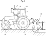
- Fig. 1 is a side view of a tractor as such a work vehicle.
- the tractor includes front wheels 11, rear wheels 12, a vehicle body 1 supported by the front wheels 11 and the rear wheels 12, and a cab 20 at a central portion of the vehicle body 1.
- the tractor is provided with a rotary tiller device as a work device 30 attached to a back portion of the vehicle body 1 via a hydraulic lifting/lowering mechanism.
- the front wheels 11 function to steer the tractor: changing their steering angle changes the direction in which the tractor travels.
- the steering angle of the front wheels 11 is changed through operation of a steering mechanism 13.
- the steering mechanism 13 includes a steering motor 14 for autonomous travel. During manual travel, the front wheels 11 are controlled through operation of a steering wheel 22 provided in the cab 20.
- the tractor is provided with a positioning unit 8 to detect the position of the tractor.
- the cab 20 contains a general-purpose data processing terminal 4.
- the data processing terminal 4 is a tablet computer including a touch screen 40 that functions as a user operation device and a notification device. The data processing terminal 4 receives various operations entered by the driver via the touch screen 40 and notifies the driver of various pieces of information.
- Fig. 2 schematically illustrates example tillage work performed by the tractor.
- the tillage work involves alternating between (i) straight travel during which the tractor travels along a linear work path while performing tillage work and (ii) turn travel through which the tractor moves to a subsequent linear work path.
- the tractor is manually driven to travel along the first linear work path, which serves as a teaching path TL.
- the tractor sets subsequent linear paths sequentially in such a pattern that the subsequent linear paths are next to one another and parallel to the teaching path TL.
- the subsequent linear paths each serve as a target travel path for autonomous travel, and are labeled as LM(1) to LM(6) in Fig. 2 .
- the description below deals with a travel process during the tillage work.
- the driver manually drives the tractor to position the vehicle body 1 at a starting point position Ts close to a ridge of the agricultural field, and then operates a manual operation tool 90 (see Fig. 3 ; hereinafter the same applies).
- the driver manually drives the tractor to cause the vehicle body 1 to travel from the starting point position Ts linearly along the ridge to a finishing point position Tf on the opposite side and close to the ridge, and then operates the manual operation tool 90 again.
- a teaching path TL to be calculated from the position coordinates of the vehicle body 1 at the starting point position Ts and the position coordinates of the vehicle body 1 at the finishing point position Tf, the teaching path TL connecting the starting point position Ts with the finishing point position Tf. If the direction of the teaching path TL has been set in advance, at least part of the teaching travel may be performed through autonomous steering.
- the driver causes the tractor to perform 180-degree turn travel to move to the starting point position Ls(1) of the first target travel path LM(1), which is adjacent to the teaching path TL.
- the control device checks whether the manual operation tool 90 was operated at a position suitable for tillage work. Such a suitable position is typically away from the position at which the tractor suspended tillage work over a distance of an integral multiple of the work width.
- the control device checks whether the vehicle body 1 has a travel deviation within an acceptable range. If the travel deviation is within the acceptable range, the vehicle body 1 resumes performing autonomous travel along the target travel path LM(1) set as a target. If the travel deviation is outside the acceptable range, the vehicle body 1 does not resume autonomous travel: the driver manually steers the tractor so that the travel deviation of the vehicle body 1 will be within the acceptable range.
- the target travel path LM(1) is a target travel path along which the vehicle body 1 performs work travel first after teaching travel.
- the driver drives the tractor along a turn travel path.
- the tractor sets a subsequent target travel path LM(2) that is adjacent to the previous target travel path LM(1) on the side of an unworked region and that extends from a starting point position Ls(2).
- the tractor repeats setting a target travel path and performing work travel in the order of target travel paths LM(3), LM(4), LM(5), and LM(6) extending from respective starting point positions Ls(3), Ls(4), Ls(5), and Ls(6) with turn travel in-between.
- the tractor includes a satellite positioning module 8a and an inertial positioning module 8b as included in the positioning unit 8.
- the satellite positioning module 8a has a satellite positioning function: it is capable of determining the position of the vehicle body 1 with use of a global positioning system (GPS), which is based on well-known art, as an example of a global navigation satellite system (GNSS) configured to receive a radio wave from a satellite and detect the position of the vehicle body 1.
- GPS global positioning system
- GNSS global navigation satellite system
- the present embodiment uses a differential GPS for satellite positioning, but may alternatively use a different GPS such as a real-time kinematic GPS (RTK-GPS).
- the inertial positioning module 8b includes a triaxial gyro sensor and a triaxial acceleration sensor.
- the inertial positioning module 8b includes, for example, a gyro sensor and an acceleration sensor, and is thereby capable of detecting the angular velocity of a turn of the vehicle body 1 (see Fig. 1 ; hereinafter the same applies).
- the inertial positioning module 8b is capable of integrating the angular velocity to determine an angular change in the vehicle body direction.
- the inertial positioning module 8b is capable of measuring not only the angular velocity of a turn of the vehicle body 1, but also, for example, the angular velocity of the left-right inclination of the vehicle body 1 and the angular velocity of the front-back inclination of the vehicle body 1.
- the inertial positioning module 8b is present at a lower position behind a driver's seat 41 (see Fig. 1 ) in the cab 20 which position is a low position at the middle in the width direction of the vehicle body 1.
- the inertial positioning module 8b may alternatively be present at a position where the satellite positioning module 8a is present.
- the control device 5 includes an input-output processing section 50 as an input-output interface.
- the input-output processing section 50 is connected to, for example, a state detector group 70 and various manual operation tools 90.
- the functional block diagram shows that the above-described positioning unit 8 is connected to the control device 5 over an in-vehicle LAN.
- the notification unit 72 is connected to a liquid crystal display 48 as a notification device.
- the liquid crystal display 48 is configured to display various information items on the basis of a notification signal transmitted from a notification control section 720 incorporated in the notification unit 72.
- the notification unit 72 is connected to the control device 5 over the in-vehicle LAN.
- the state detector group 70 includes various sensors, switches, and the like such as a travel device state detector 74 and a work device state detector 75.
- the travel device state detector 74 includes travel state detecting sensors such as a vehicle speed sensor, a steering angle sensor, an engine rotation speed sensor, a brake pedal detecting sensor, and a parking brake detecting sensor (not illustrated in the drawings).
- the work device state detector 75 includes sensors for detecting the respective states of various mechanisms included in the work device 30 (see Fig. 1 ; hereinafter the same applies) such as a lifting/lowering mechanism.
- the manual operation tools 90 are a general name for tools such as a lever, a switch, a button, and a volume control.
- the manual operation tools 90 are each operable by the driver for transmission of a control command to the control device 5.
- the control device 5 includes a vehicle position calculating section 80, a travel direction calculating section 81, a travel control section 51, a work control section 52, a teaching management section 53, a path setting section 54, a vehicle speed calculating section 55, a steering state obtaining section 56, and a steering amount computing unit 6.
- the vehicle position calculating section 80 calculates the map coordinates of the vehicle body 1 (that is, the vehicle position) on the basis of satellite positioning data transmitted sequentially from the positioning unit 8. During the calculation, the vehicle position calculating section 80 converts the position calculated directly from satellite positioning data into a benchmark point on the vehicle body 1 (for example, the position of the vehicle body center or work center of the work device 30).
- the travel direction calculating section 81 processes data on vehicle positions (calculated by the vehicle position calculating section 80) over time to calculate the travel direction of the vehicle body 1, that is, its front-back direction.
- the travel control section 51 transmits a steering control signal to the steering motor 14 (see Fig. 1 ) and signals such as a speed change control signal and a braking control signal to a travel device such as a transmission (not illustrated in the drawings).
- the travel control section 51 includes an autonomous travel control section 511, a manual travel control section 512, and a travel mode management section 513 in order for the tractor to selectively travel autonomously or be driven manually.
- the tractor is set to an autonomous travel mode to drive itself autonomously or a manual travel mode to be driven manually. These travel modes are managed by the travel mode management section 513.
- the autonomous travel control section 511 receives autonomous steering data (that is, data on a target steering amount) from the steering amount computing unit 6.
- the work control section 52 controls lifting and lowering of the work device 30 and transmission of power to the work device 30 while the vehicle body 1 is traveling.
- the teaching management section 53 calculates data on a teaching path TL (such as map coordinates) on the basis of the teaching travel described above.
- the path setting section 54 sets a target travel path as a target of autonomous travel (for the present embodiment, a path for straight, autonomously steered travel) through the procedure described above with reference to Fig. 2 .
- the vehicle speed calculating section 55 calculates the speed of the tractor on the basis of a signal from a vehicle speed sensor or the amount of change of the vehicle position over time.
- the steering state obtaining section 56 obtains data on the steering state of the tractor (such as the steering angle) on the basis of a signal from a steering sensor configured to detect the state of a steering device.
- the steering amount computing unit 6 determines an estimated vehicle position, that is, a position at which the tractor will be present after performing predetermined travel from the current vehicle position.
- the steering amount calculating unit 6 then calculates a target steering amount on the basis of a deviation(s) (namely, either or both of a positional deviation and a directional deviation) calculated on the basis of the estimated vehicle position.
- the steering amount calculating unit 6 transmits data on the target steering amount to the autonomous travel control section 511.
- the steering amount computing unit 6 includes a vehicle position estimating section 61, a deviation calculating section 62, and a target steering amount calculating section 63 as illustrated in Fig. 4 .
- the vehicle position estimating section 61 calculates an estimated vehicle position, that is, a position at which the work vehicle will be present after performing predetermined travel from the current vehicle position calculated by the vehicle position calculating section 80.
- the deviation calculating section 62 calculates a deviation of the work vehicle at the estimated vehicle position, calculated by the vehicle position estimating section 61, from the target travel path.
- the target steering amount calculating section 63 calculates, on the basis of the deviation (calculated by the deviation calculating section 62), a target steering amount intended to reduce the deviation.
- the vehicle position estimating section 61 calculates an estimated vehicle position by, for example, any of the methods described below with reference to Fig. 5.
- Fig. 5 shows that the vehicle body 1 is currently deviated to the right in the drawing from a target travel path (indicated as "TL” in Fig. 5 ) and that the travel direction line of the vehicle body 1 (indicated as "DL” in Fig. 5 ), that is, its front-back direction, is inclined relative to the target travel path.
- the vehicle position estimating section 61 calculates an estimated vehicle position by at least one of the estimated vehicle position calculating methods described above and any methods similar thereto.
- the vehicle position estimating section 61 may use a plurality of estimated vehicle position calculating methods so that one of the estimated vehicle positions calculated is selected by a person or automatically according to the work state of the tractor. Further, the above predetermined distance and predetermined time length for use in the calculation by the vehicle position estimating section 61 may be selected by a person, automatically without a condition, or automatically according to the work state of the tractor.
- the vehicle position estimating section 61 also calculates an estimated travel direction, that is, the travel direction of the vehicle body 1 at the estimated vehicle position.
- the deviation calculating section 62 calculates (i) an estimated lateral deviation, that is, the lateral deviation of the vehicle body 1 at the estimated vehicle position calculated, and (ii) an estimated directional deviation, that is, the directional deviation of the vehicle body 1 at the estimated vehicle position.
- An estimated lateral deviation refers to the distance in the direction orthogonal to the direction of the target travel path between the benchmark point on the vehicle body 1 at the estimated vehicle position and a target travel path.
- An estimated directional deviation refers to the angle formed by the estimated travel direction and the target travel path.
- the deviation calculating section 62 for the present embodiment includes an estimated lateral deviation calculating section 621, an estimated directional deviation calculating section 622, and a computing element 623.
- the estimated lateral deviation calculating section 621 calculates an estimated lateral deviation.
- Fig. 5 shows ⁇ d1 to ⁇ d4 to each indicate an estimated lateral deviation calculated.
- the estimated directional deviation calculating section 622 calculates an estimated directional deviation.
- the estimated travel direction is the same as the current travel direction of the vehicle body 1 (indicated as " ⁇ " in Fig. 5 ).
- the estimated travel direction is calculated on the basis of the travel direction of the vehicle body 1 at the estimated vehicle position on the expected travel pathway.
- Fig. 5 shows ⁇ 3 and ⁇ 4 to each indicate an estimated travel direction.
- the computing element 623 receives, as input parameters, data on an estimated lateral deviation calculated by the estimated lateral deviation calculating section 621 and data on an estimated directional deviation calculated by the estimated directional deviation calculating section 622. The computing element 623 then, for example, weights the input parameters and outputs the resulting deviation data.
- the deviation calculating section 62 may alternatively include only either the estimated lateral deviation calculating section 621 or the estimated directional deviation calculating section 622. Further alternatively, the estimated lateral deviation calculating section 621 and the estimated directional deviation calculating section 622 may be used selectively.
- the deviation data outputted by the deviation calculating section 62 is received by the target steering amount calculating section 63 as an input parameter.
- the target steering amount calculating section 63 may alternatively receive, instead of the deviation data outputted by the deviation calculating section 62, the data on an estimated lateral deviation and the data on an estimated directional deviation as input parameters.
- the target steering amount calculating section 63 may be in the form of, for example, a PI controller or PID controller.
- the present invention is applicable to any agricultural field work vehicle configured to travel autonomously along a target travel path in an agricultural field.
Landscapes
- Engineering & Computer Science (AREA)
- Radar, Positioning & Navigation (AREA)
- Remote Sensing (AREA)
- General Physics & Mathematics (AREA)
- Aviation & Aerospace Engineering (AREA)
- Physics & Mathematics (AREA)
- Automation & Control Theory (AREA)
- Life Sciences & Earth Sciences (AREA)
- Environmental Sciences (AREA)
- Soil Sciences (AREA)
- Mechanical Engineering (AREA)
- Guiding Agricultural Machines (AREA)
- Control Of Position, Course, Altitude, Or Attitude Of Moving Bodies (AREA)
- Steering Control In Accordance With Driving Conditions (AREA)
Claims (9)
- Dispositif de commande (5) destiné à un véhicule de chantier conçu pour se déplacer de manière autonome le long d'un trajet de déplacement cible, le dispositif de commande (5) comprenant :une section (80) de calcul de position de véhicule, conçue pour calculer une position du véhicule de chantier ;une section (81) de calcul de direction de déplacement, conçue pour calculer une direction de déplacement du véhicule de chantier, la direction de déplacement étant une direction avant-arrière d'un corps (1) du véhicule de chantier ;une section (56) d'obtention d'état de braquage, conçue pour obtenir des données concernant un état du braquage du véhicule de chantier ;une section (61) d'estimation de position de véhicule, conçue pour calculer une position estimée du véhicule au niveau de laquelle le véhicule de chantier devrait être présent après la réalisation d'un déplacement prédéfini à partir de ladite position du véhicule de chantier ;une section (62) de calcul d'écart, conçue pour calculer un écart du véhicule de chantier au niveau de la position estimée du véhicule par rapport au trajet de déplacement cible ;une section (621) de calcul d'écart latéral estimé, conçue pour calculer un écart latéral estimé, l'écart latéral estimé étant une distance entre la position estimée du véhicule et le trajet de déplacement cible dans une direction orthogonale à une direction du trajet de déplacement cible ;une section (622) de calcul d'écart directionnel estimé, conçue pour calculer un écart directionnel estimé, l'écart directionnel estimé étant un angle formé par une direction de déplacement estimée du véhicule de chantier, au niveau de la position estimée du véhicule, et le trajet de déplacement cible ;une section (63) de calcul de quantité de braquage cible, conçue pour calculer une quantité de braquage cible en fonction de l'écart latéral estimé et de l'écart directionnel estimé ; etune section (511) de commande de déplacement autonome, conçue pour commander le braquage du véhicule de chantier en fonction de la quantité de braquage cible.
- Le dispositif de commande (5) selon la revendication 1, comprenant en outre :une section (55) de calcul de vitesse de véhicule, conçue pour calculer une vitesse du véhicule de chantier,la section (61) d'estimation de position de véhicule étant conçue pour calculer, en tant que position estimée du véhicule, une position au niveau de laquelle le véhicule de chantier devrait être présent après le déplacement à la vitesse du véhicule, pendant une durée de temps prédéfinie, dans la direction de déplacement calculée par la section (81) de calcul de direction de déplacement.
- Le dispositif de commande (5) selon la revendication 1, comprenant en outre :une section (55) de calcul de vitesse de véhicule, conçue pour calculer une vitesse du véhicule de chantier,la section (61) d'estimation de position de véhicule étant conçue pour calculer, en tant que position estimée du véhicule, une position au niveau de laquelle le véhicule de chantier devrait être présent après le déplacement à la vitesse du véhicule dans l'état de braquage pendant une durée de temps prédéfinie.
- Le dispositif de commande (5) selon les revendications 2 ou 3, dans lequel
la durée de temps prédéfinie peut être choisie par un utilisateur. - Le dispositif de commande (5) selon les revendications 2 ou 3, dans lequel
la durée de temps prédéfinie est choisie automatiquement selon un état de travail du véhicule de chantier. - Le dispositif de commande (5) selon la revendication 1, dans lequel
la section (61) d'estimation de position de véhicule est conçue pour calculer, en tant que position estimée du véhicule, une position au niveau de laquelle le véhicule de chantier devrait être présent après le déplacement sur une distance prédéfinie dans la direction de déplacement calculée par la section (81) de calcul de direction de déplacement. - Le dispositif de commande (5) selon la revendication 1, dans lequel
la section (61) d'estimation de position de véhicule est conçue pour calculer, en tant que position estimée du véhicule, une position au niveau de laquelle le véhicule de chantier devrait être présent après le déplacement sur une distance prédéfinie dans l'état de braquage. - Le dispositif de commande (5) selon les revendications 6 ou 7, dans lequel
la distance prédéfinie peut être choisie par un utilisateur. - Le dispositif de commande (5) selon les revendications 6 ou 7, dans lequel
la distance prédéfinie peut être choisie automatiquement selon un état de travail du véhicule de chantier.
Applications Claiming Priority (2)
| Application Number | Priority Date | Filing Date | Title |
|---|---|---|---|
| JP2018238895A JP7072496B2 (ja) | 2018-12-20 | 2018-12-20 | 自動走行作業車のための制御装置 |
| PCT/JP2019/048044 WO2020129722A1 (fr) | 2018-12-20 | 2019-12-09 | Dispositif de commande pour véhicule de travail à déplacement automatique |
Publications (3)
| Publication Number | Publication Date |
|---|---|
| EP3900505A1 EP3900505A1 (fr) | 2021-10-27 |
| EP3900505A4 EP3900505A4 (fr) | 2022-09-14 |
| EP3900505B1 true EP3900505B1 (fr) | 2024-08-14 |
Family
ID=71100769
Family Applications (1)
| Application Number | Title | Priority Date | Filing Date |
|---|---|---|---|
| EP19897852.0A Active EP3900505B1 (fr) | 2018-12-20 | 2019-12-09 | Dispositif de commande pour véhicule de travail à déplacement automatique |
Country Status (4)
| Country | Link |
|---|---|
| US (1) | US11937526B2 (fr) |
| EP (1) | EP3900505B1 (fr) |
| JP (1) | JP7072496B2 (fr) |
| WO (1) | WO2020129722A1 (fr) |
Families Citing this family (10)
| Publication number | Priority date | Publication date | Assignee | Title |
|---|---|---|---|---|
| JP6766240B1 (ja) * | 2019-09-06 | 2020-10-07 | 株式会社クボタ | 作業車両 |
| EP4080273A4 (fr) | 2019-12-17 | 2023-06-28 | Xtia Ltd | Procédé de production d'un résonateur optique et d'un modulateur optique, résonateur optique, modulateur optique, générateur de peigne de fréquences optiques et oscillateur optique |
| CN111767507A (zh) * | 2020-06-30 | 2020-10-13 | 北京百度网讯科技有限公司 | 一种倒车轨迹追踪方法、装置、电子设备及存储介质 |
| CN112678726B (zh) * | 2020-12-18 | 2022-07-29 | 江苏智库智能科技有限公司 | 基于叉车式agv运动学模型的取货定位方法及系统 |
| CN113359743A (zh) * | 2021-06-18 | 2021-09-07 | 北京盈迪曼德科技有限公司 | 机器人任务执行方法、装置、机器人及存储介质 |
| JP7784451B2 (ja) | 2022-01-21 | 2025-12-11 | 株式会社キャタラー | 排ガス浄化用触媒 |
| US12208834B2 (en) * | 2022-03-31 | 2025-01-28 | Caterpillar Inc. | Systems and methods for machine steering |
| JP7756067B2 (ja) * | 2022-12-28 | 2025-10-17 | 株式会社クボタ | 作業車両、作業車両の制御システムおよび制御方法 |
| JP2024116593A (ja) * | 2023-02-16 | 2024-08-28 | ヤンマーホールディングス株式会社 | 自動操舵方法、自動操舵システム、及び自動操舵プログラム |
| JP2025103407A (ja) * | 2023-12-27 | 2025-07-09 | 株式会社クボタ | 作業車両、および作業車両を制御する方法 |
Family Cites Families (7)
| Publication number | Priority date | Publication date | Assignee | Title |
|---|---|---|---|---|
| JP2573939B2 (ja) | 1987-02-16 | 1997-01-22 | 株式会社クボタ | 自動走行作業車の走行制御装置 |
| JPH06300580A (ja) * | 1993-04-15 | 1994-10-28 | Fuji Heavy Ind Ltd | 車輛の軌道追従制御装置 |
| JP4295911B2 (ja) | 2000-12-19 | 2009-07-15 | ヤンマー農機株式会社 | 農業用作業車 |
| JP5593606B2 (ja) | 2008-11-28 | 2014-09-24 | 株式会社ジェイテクト | 走行支援装置 |
| JP6497546B2 (ja) | 2015-02-06 | 2019-04-10 | 国立研究開発法人農業・食品産業技術総合研究機構 | 走行制御装置 |
| JP6420173B2 (ja) | 2015-02-25 | 2018-11-07 | 株式会社クボタ | 自動走行圃場作業車両 |
| JP6811655B2 (ja) | 2017-03-14 | 2021-01-13 | 株式会社クボタ | 作業車 |
-
2018
- 2018-12-20 JP JP2018238895A patent/JP7072496B2/ja active Active
-
2019
- 2019-12-09 WO PCT/JP2019/048044 patent/WO2020129722A1/fr not_active Ceased
- 2019-12-09 EP EP19897852.0A patent/EP3900505B1/fr active Active
- 2019-12-09 US US17/297,526 patent/US11937526B2/en active Active
Also Published As
| Publication number | Publication date |
|---|---|
| EP3900505A4 (fr) | 2022-09-14 |
| US11937526B2 (en) | 2024-03-26 |
| JP7072496B2 (ja) | 2022-05-20 |
| JP2020099226A (ja) | 2020-07-02 |
| US20220007563A1 (en) | 2022-01-13 |
| EP3900505A1 (fr) | 2021-10-27 |
| WO2020129722A1 (fr) | 2020-06-25 |
Similar Documents
| Publication | Publication Date | Title |
|---|---|---|
| EP3900505B1 (fr) | Dispositif de commande pour véhicule de travail à déplacement automatique | |
| JP7277520B2 (ja) | 作業車 | |
| JP7779966B2 (ja) | トラクタ | |
| EP3467606B1 (fr) | Véhicule de travail autonome | |
| EP3176665B1 (fr) | Système de coopération pour véhicules de travail | |
| US20180310461A1 (en) | Control apparatus for automatic traveling vehicle | |
| EP4068036B1 (fr) | Système de commande de déplacement autonome | |
| JP2024164121A5 (fr) | ||
| EP3900509A1 (fr) | Véhicule agricole | |
| JP2020137463A (ja) | 自律走行システム | |
| WO2018163615A1 (fr) | Système de génération d'itinéraire | |
| JP2019097503A (ja) | 走行作業機 | |
| JP7386757B2 (ja) | 作業車両の自律走行システム | |
| JP2021108576A (ja) | 作業車両 | |
| JP2020164160A (ja) | 自動走行圃場作業車両 | |
| JP6871831B2 (ja) | 作業車両用の自律走行システム | |
| US12208834B2 (en) | Systems and methods for machine steering | |
| JP7146675B2 (ja) | 自動走行システム | |
| JP2019053471A (ja) | 作業車両用の自律走行システム | |
| JP7068969B2 (ja) | 自動走行システム | |
| WO2022149389A1 (fr) | Système de trajet automatique et procédé de trajet automatique | |
| JP7329645B2 (ja) | 作業支援システム | |
| JP2021108578A (ja) | 作業車両及び田植機 | |
| WO2023112611A1 (fr) | Système de pilotage automatique | |
| JP2023078169A (ja) | 経路生成システム及び経路生成方法 |
Legal Events
| Date | Code | Title | Description |
|---|---|---|---|
| STAA | Information on the status of an ep patent application or granted ep patent |
Free format text: STATUS: THE INTERNATIONAL PUBLICATION HAS BEEN MADE |
|
| PUAI | Public reference made under article 153(3) epc to a published international application that has entered the european phase |
Free format text: ORIGINAL CODE: 0009012 |
|
| STAA | Information on the status of an ep patent application or granted ep patent |
Free format text: STATUS: REQUEST FOR EXAMINATION WAS MADE |
|
| 17P | Request for examination filed |
Effective date: 20210624 |
|
| AK | Designated contracting states |
Kind code of ref document: A1 Designated state(s): AL AT BE BG CH CY CZ DE DK EE ES FI FR GB GR HR HU IE IS IT LI LT LU LV MC MK MT NL NO PL PT RO RS SE SI SK SM TR |
|
| DAV | Request for validation of the european patent (deleted) | ||
| DAX | Request for extension of the european patent (deleted) | ||
| A4 | Supplementary search report drawn up and despatched |
Effective date: 20220817 |
|
| RIC1 | Information provided on ipc code assigned before grant |
Ipc: B62D 6/00 20060101ALN20220810BHEP Ipc: B62D 15/02 20060101ALN20220810BHEP Ipc: G05D 1/02 20200101ALI20220810BHEP Ipc: A01B 69/04 20060101AFI20220810BHEP |
|
| REG | Reference to a national code |
Ref country code: DE Ref legal event code: R079 Free format text: PREVIOUS MAIN CLASS: A01B0069000000 Ipc: A01B0069040000 Ref country code: DE Ref legal event code: R079 Ref document number: 602019057172 Country of ref document: DE Free format text: PREVIOUS MAIN CLASS: A01B0069000000 Ipc: A01B0069040000 |
|
| GRAP | Despatch of communication of intention to grant a patent |
Free format text: ORIGINAL CODE: EPIDOSNIGR1 |
|
| STAA | Information on the status of an ep patent application or granted ep patent |
Free format text: STATUS: GRANT OF PATENT IS INTENDED |
|
| RIC1 | Information provided on ipc code assigned before grant |
Ipc: B62D 6/00 20060101ALN20240314BHEP Ipc: B62D 15/02 20060101ALN20240314BHEP Ipc: G05D 1/00 20060101ALI20240314BHEP Ipc: A01B 69/04 20060101AFI20240314BHEP |
|
| INTG | Intention to grant announced |
Effective date: 20240328 |
|
| GRAS | Grant fee paid |
Free format text: ORIGINAL CODE: EPIDOSNIGR3 |
|
| GRAA | (expected) grant |
Free format text: ORIGINAL CODE: 0009210 |
|
| STAA | Information on the status of an ep patent application or granted ep patent |
Free format text: STATUS: THE PATENT HAS BEEN GRANTED |
|
| AK | Designated contracting states |
Kind code of ref document: B1 Designated state(s): AL AT BE BG CH CY CZ DE DK EE ES FI FR GB GR HR HU IE IS IT LI LT LU LV MC MK MT NL NO PL PT RO RS SE SI SK SM TR |
|
| REG | Reference to a national code |
Ref country code: GB Ref legal event code: FG4D |
|
| REG | Reference to a national code |
Ref country code: CH Ref legal event code: EP |
|
| REG | Reference to a national code |
Ref country code: DE Ref legal event code: R096 Ref document number: 602019057172 Country of ref document: DE |
|
| REG | Reference to a national code |
Ref country code: IE Ref legal event code: FG4D |
|
| REG | Reference to a national code |
Ref country code: LT Ref legal event code: MG9D |
|
| REG | Reference to a national code |
Ref country code: NL Ref legal event code: MP Effective date: 20240814 |
|
| PG25 | Lapsed in a contracting state [announced via postgrant information from national office to epo] |
Ref country code: NO Free format text: LAPSE BECAUSE OF FAILURE TO SUBMIT A TRANSLATION OF THE DESCRIPTION OR TO PAY THE FEE WITHIN THE PRESCRIBED TIME-LIMIT Effective date: 20241114 |
|
| REG | Reference to a national code |
Ref country code: AT Ref legal event code: MK05 Ref document number: 1712355 Country of ref document: AT Kind code of ref document: T Effective date: 20240814 |
|
| PG25 | Lapsed in a contracting state [announced via postgrant information from national office to epo] |
Ref country code: FI Free format text: LAPSE BECAUSE OF FAILURE TO SUBMIT A TRANSLATION OF THE DESCRIPTION OR TO PAY THE FEE WITHIN THE PRESCRIBED TIME-LIMIT Effective date: 20240814 Ref country code: NL Free format text: LAPSE BECAUSE OF FAILURE TO SUBMIT A TRANSLATION OF THE DESCRIPTION OR TO PAY THE FEE WITHIN THE PRESCRIBED TIME-LIMIT Effective date: 20240814 Ref country code: PL Free format text: LAPSE BECAUSE OF FAILURE TO SUBMIT A TRANSLATION OF THE DESCRIPTION OR TO PAY THE FEE WITHIN THE PRESCRIBED TIME-LIMIT Effective date: 20240814 Ref country code: GR Free format text: LAPSE BECAUSE OF FAILURE TO SUBMIT A TRANSLATION OF THE DESCRIPTION OR TO PAY THE FEE WITHIN THE PRESCRIBED TIME-LIMIT Effective date: 20241115 Ref country code: PT Free format text: LAPSE BECAUSE OF FAILURE TO SUBMIT A TRANSLATION OF THE DESCRIPTION OR TO PAY THE FEE WITHIN THE PRESCRIBED TIME-LIMIT Effective date: 20241216 |
|
| PG25 | Lapsed in a contracting state [announced via postgrant information from national office to epo] |
Ref country code: BG Free format text: LAPSE BECAUSE OF FAILURE TO SUBMIT A TRANSLATION OF THE DESCRIPTION OR TO PAY THE FEE WITHIN THE PRESCRIBED TIME-LIMIT Effective date: 20240814 |
|
| PG25 | Lapsed in a contracting state [announced via postgrant information from national office to epo] |
Ref country code: LV Free format text: LAPSE BECAUSE OF FAILURE TO SUBMIT A TRANSLATION OF THE DESCRIPTION OR TO PAY THE FEE WITHIN THE PRESCRIBED TIME-LIMIT Effective date: 20240814 |
|
| PG25 | Lapsed in a contracting state [announced via postgrant information from national office to epo] |
Ref country code: IS Free format text: LAPSE BECAUSE OF FAILURE TO SUBMIT A TRANSLATION OF THE DESCRIPTION OR TO PAY THE FEE WITHIN THE PRESCRIBED TIME-LIMIT Effective date: 20241214 Ref country code: AT Free format text: LAPSE BECAUSE OF FAILURE TO SUBMIT A TRANSLATION OF THE DESCRIPTION OR TO PAY THE FEE WITHIN THE PRESCRIBED TIME-LIMIT Effective date: 20240814 |
|
| PG25 | Lapsed in a contracting state [announced via postgrant information from national office to epo] |
Ref country code: HR Free format text: LAPSE BECAUSE OF FAILURE TO SUBMIT A TRANSLATION OF THE DESCRIPTION OR TO PAY THE FEE WITHIN THE PRESCRIBED TIME-LIMIT Effective date: 20240814 |
|
| PG25 | Lapsed in a contracting state [announced via postgrant information from national office to epo] |
Ref country code: ES Free format text: LAPSE BECAUSE OF FAILURE TO SUBMIT A TRANSLATION OF THE DESCRIPTION OR TO PAY THE FEE WITHIN THE PRESCRIBED TIME-LIMIT Effective date: 20240814 Ref country code: RS Free format text: LAPSE BECAUSE OF FAILURE TO SUBMIT A TRANSLATION OF THE DESCRIPTION OR TO PAY THE FEE WITHIN THE PRESCRIBED TIME-LIMIT Effective date: 20241114 |
|
| PG25 | Lapsed in a contracting state [announced via postgrant information from national office to epo] |
Ref country code: RS Free format text: LAPSE BECAUSE OF FAILURE TO SUBMIT A TRANSLATION OF THE DESCRIPTION OR TO PAY THE FEE WITHIN THE PRESCRIBED TIME-LIMIT Effective date: 20241114 Ref country code: PT Free format text: LAPSE BECAUSE OF FAILURE TO SUBMIT A TRANSLATION OF THE DESCRIPTION OR TO PAY THE FEE WITHIN THE PRESCRIBED TIME-LIMIT Effective date: 20241216 Ref country code: PL Free format text: LAPSE BECAUSE OF FAILURE TO SUBMIT A TRANSLATION OF THE DESCRIPTION OR TO PAY THE FEE WITHIN THE PRESCRIBED TIME-LIMIT Effective date: 20240814 Ref country code: NO Free format text: LAPSE BECAUSE OF FAILURE TO SUBMIT A TRANSLATION OF THE DESCRIPTION OR TO PAY THE FEE WITHIN THE PRESCRIBED TIME-LIMIT Effective date: 20241114 Ref country code: NL Free format text: LAPSE BECAUSE OF FAILURE TO SUBMIT A TRANSLATION OF THE DESCRIPTION OR TO PAY THE FEE WITHIN THE PRESCRIBED TIME-LIMIT Effective date: 20240814 Ref country code: LV Free format text: LAPSE BECAUSE OF FAILURE TO SUBMIT A TRANSLATION OF THE DESCRIPTION OR TO PAY THE FEE WITHIN THE PRESCRIBED TIME-LIMIT Effective date: 20240814 Ref country code: IS Free format text: LAPSE BECAUSE OF FAILURE TO SUBMIT A TRANSLATION OF THE DESCRIPTION OR TO PAY THE FEE WITHIN THE PRESCRIBED TIME-LIMIT Effective date: 20241214 Ref country code: HR Free format text: LAPSE BECAUSE OF FAILURE TO SUBMIT A TRANSLATION OF THE DESCRIPTION OR TO PAY THE FEE WITHIN THE PRESCRIBED TIME-LIMIT Effective date: 20240814 Ref country code: GR Free format text: LAPSE BECAUSE OF FAILURE TO SUBMIT A TRANSLATION OF THE DESCRIPTION OR TO PAY THE FEE WITHIN THE PRESCRIBED TIME-LIMIT Effective date: 20241115 Ref country code: FI Free format text: LAPSE BECAUSE OF FAILURE TO SUBMIT A TRANSLATION OF THE DESCRIPTION OR TO PAY THE FEE WITHIN THE PRESCRIBED TIME-LIMIT Effective date: 20240814 Ref country code: ES Free format text: LAPSE BECAUSE OF FAILURE TO SUBMIT A TRANSLATION OF THE DESCRIPTION OR TO PAY THE FEE WITHIN THE PRESCRIBED TIME-LIMIT Effective date: 20240814 Ref country code: BG Free format text: LAPSE BECAUSE OF FAILURE TO SUBMIT A TRANSLATION OF THE DESCRIPTION OR TO PAY THE FEE WITHIN THE PRESCRIBED TIME-LIMIT Effective date: 20240814 Ref country code: AT Free format text: LAPSE BECAUSE OF FAILURE TO SUBMIT A TRANSLATION OF THE DESCRIPTION OR TO PAY THE FEE WITHIN THE PRESCRIBED TIME-LIMIT Effective date: 20240814 |
|
| PG25 | Lapsed in a contracting state [announced via postgrant information from national office to epo] |
Ref country code: RO Free format text: LAPSE BECAUSE OF FAILURE TO SUBMIT A TRANSLATION OF THE DESCRIPTION OR TO PAY THE FEE WITHIN THE PRESCRIBED TIME-LIMIT Effective date: 20240814 Ref country code: SM Free format text: LAPSE BECAUSE OF FAILURE TO SUBMIT A TRANSLATION OF THE DESCRIPTION OR TO PAY THE FEE WITHIN THE PRESCRIBED TIME-LIMIT Effective date: 20240814 Ref country code: DK Free format text: LAPSE BECAUSE OF FAILURE TO SUBMIT A TRANSLATION OF THE DESCRIPTION OR TO PAY THE FEE WITHIN THE PRESCRIBED TIME-LIMIT Effective date: 20240814 |
|
| PG25 | Lapsed in a contracting state [announced via postgrant information from national office to epo] |
Ref country code: EE Free format text: LAPSE BECAUSE OF FAILURE TO SUBMIT A TRANSLATION OF THE DESCRIPTION OR TO PAY THE FEE WITHIN THE PRESCRIBED TIME-LIMIT Effective date: 20240814 |
|
| PG25 | Lapsed in a contracting state [announced via postgrant information from national office to epo] |
Ref country code: CZ Free format text: LAPSE BECAUSE OF FAILURE TO SUBMIT A TRANSLATION OF THE DESCRIPTION OR TO PAY THE FEE WITHIN THE PRESCRIBED TIME-LIMIT Effective date: 20240814 |
|
| PG25 | Lapsed in a contracting state [announced via postgrant information from national office to epo] |
Ref country code: IT Free format text: LAPSE BECAUSE OF FAILURE TO SUBMIT A TRANSLATION OF THE DESCRIPTION OR TO PAY THE FEE WITHIN THE PRESCRIBED TIME-LIMIT Effective date: 20240814 Ref country code: SK Free format text: LAPSE BECAUSE OF FAILURE TO SUBMIT A TRANSLATION OF THE DESCRIPTION OR TO PAY THE FEE WITHIN THE PRESCRIBED TIME-LIMIT Effective date: 20240814 |
|
| REG | Reference to a national code |
Ref country code: DE Ref legal event code: R097 Ref document number: 602019057172 Country of ref document: DE |
|
| PLBE | No opposition filed within time limit |
Free format text: ORIGINAL CODE: 0009261 |
|
| STAA | Information on the status of an ep patent application or granted ep patent |
Free format text: STATUS: NO OPPOSITION FILED WITHIN TIME LIMIT |
|
| PG25 | Lapsed in a contracting state [announced via postgrant information from national office to epo] |
Ref country code: MC Free format text: LAPSE BECAUSE OF FAILURE TO SUBMIT A TRANSLATION OF THE DESCRIPTION OR TO PAY THE FEE WITHIN THE PRESCRIBED TIME-LIMIT Effective date: 20240814 |
|
| 26N | No opposition filed |
Effective date: 20250515 |
|
| REG | Reference to a national code |
Ref country code: CH Ref legal event code: PL |
|
| PG25 | Lapsed in a contracting state [announced via postgrant information from national office to epo] |
Ref country code: LU Free format text: LAPSE BECAUSE OF NON-PAYMENT OF DUE FEES Effective date: 20241209 |
|
| GBPC | Gb: european patent ceased through non-payment of renewal fee |
Effective date: 20241209 |
|
| PG25 | Lapsed in a contracting state [announced via postgrant information from national office to epo] |
Ref country code: SE Free format text: LAPSE BECAUSE OF FAILURE TO SUBMIT A TRANSLATION OF THE DESCRIPTION OR TO PAY THE FEE WITHIN THE PRESCRIBED TIME-LIMIT Effective date: 20240814 |
|
| REG | Reference to a national code |
Ref country code: BE Ref legal event code: MM Effective date: 20241231 |
|
| PG25 | Lapsed in a contracting state [announced via postgrant information from national office to epo] |
Ref country code: BE Free format text: LAPSE BECAUSE OF NON-PAYMENT OF DUE FEES Effective date: 20241231 Ref country code: GB Free format text: LAPSE BECAUSE OF NON-PAYMENT OF DUE FEES Effective date: 20241209 |
|
| PG25 | Lapsed in a contracting state [announced via postgrant information from national office to epo] |
Ref country code: CH Free format text: LAPSE BECAUSE OF NON-PAYMENT OF DUE FEES Effective date: 20241231 |
|
| PG25 | Lapsed in a contracting state [announced via postgrant information from national office to epo] |
Ref country code: IE Free format text: LAPSE BECAUSE OF NON-PAYMENT OF DUE FEES Effective date: 20241209 |
|
| PGFP | Annual fee paid to national office [announced via postgrant information from national office to epo] |
Ref country code: DE Payment date: 20251028 Year of fee payment: 7 |
|
| PGFP | Annual fee paid to national office [announced via postgrant information from national office to epo] |
Ref country code: FR Payment date: 20251110 Year of fee payment: 7 |