EP3900516A1 - Dispositif de fauchage de couverture végétale entre barrages et sur les flancs des barrages - Google Patents
Dispositif de fauchage de couverture végétale entre barrages et sur les flancs des barrages Download PDFInfo
- Publication number
- EP3900516A1 EP3900516A1 EP21169288.4A EP21169288A EP3900516A1 EP 3900516 A1 EP3900516 A1 EP 3900516A1 EP 21169288 A EP21169288 A EP 21169288A EP 3900516 A1 EP3900516 A1 EP 3900516A1
- Authority
- EP
- European Patent Office
- Prior art keywords
- rotating element
- dam
- guide wheel
- dams
- housing
- Prior art date
- Legal status (The legal status is an assumption and is not a legal conclusion. Google has not performed a legal analysis and makes no representation as to the accuracy of the status listed.)
- Granted
Links
Images


Classifications
-
- A—HUMAN NECESSITIES
- A01—AGRICULTURE; FORESTRY; ANIMAL HUSBANDRY; HUNTING; TRAPPING; FISHING
- A01D—HARVESTING; MOWING
- A01D34/00—Mowers; Mowing apparatus of harvesters
- A01D34/835—Mowers; Mowing apparatus of harvesters specially adapted for particular purposes
- A01D34/86—Mowers; Mowing apparatus of harvesters specially adapted for particular purposes for use on sloping ground, e.g. on embankments or in ditches
-
- A—HUMAN NECESSITIES
- A01—AGRICULTURE; FORESTRY; ANIMAL HUSBANDRY; HUNTING; TRAPPING; FISHING
- A01D—HARVESTING; MOWING
- A01D34/00—Mowers; Mowing apparatus of harvesters
- A01D34/01—Mowers; Mowing apparatus of harvesters characterised by features relating to the type of cutting apparatus
- A01D34/412—Mowers; Mowing apparatus of harvesters characterised by features relating to the type of cutting apparatus having rotating cutters
- A01D34/63—Mowers; Mowing apparatus of harvesters characterised by features relating to the type of cutting apparatus having rotating cutters having cutters rotating about a vertical axis
-
- A—HUMAN NECESSITIES
- A01—AGRICULTURE; FORESTRY; ANIMAL HUSBANDRY; HUNTING; TRAPPING; FISHING
- A01D—HARVESTING; MOWING
- A01D34/00—Mowers; Mowing apparatus of harvesters
- A01D34/01—Mowers; Mowing apparatus of harvesters characterised by features relating to the type of cutting apparatus
- A01D34/412—Mowers; Mowing apparatus of harvesters characterised by features relating to the type of cutting apparatus having rotating cutters
- A01D34/63—Mowers; Mowing apparatus of harvesters characterised by features relating to the type of cutting apparatus having rotating cutters having cutters rotating about a vertical axis
- A01D34/64—Mowers; Mowing apparatus of harvesters characterised by features relating to the type of cutting apparatus having rotating cutters having cutters rotating about a vertical axis mounted on a vehicle, e.g. a tractor, or drawn by an animal or a vehicle
-
- A—HUMAN NECESSITIES
- A01—AGRICULTURE; FORESTRY; ANIMAL HUSBANDRY; HUNTING; TRAPPING; FISHING
- A01D—HARVESTING; MOWING
- A01D34/00—Mowers; Mowing apparatus of harvesters
- A01D34/01—Mowers; Mowing apparatus of harvesters characterised by features relating to the type of cutting apparatus
- A01D34/412—Mowers; Mowing apparatus of harvesters characterised by features relating to the type of cutting apparatus having rotating cutters
- A01D34/63—Mowers; Mowing apparatus of harvesters characterised by features relating to the type of cutting apparatus having rotating cutters having cutters rotating about a vertical axis
- A01D34/81—Casings; Housings
-
- A—HUMAN NECESSITIES
- A01—AGRICULTURE; FORESTRY; ANIMAL HUSBANDRY; HUNTING; TRAPPING; FISHING
- A01D—HARVESTING; MOWING
- A01D34/00—Mowers; Mowing apparatus of harvesters
- A01D34/835—Mowers; Mowing apparatus of harvesters specially adapted for particular purposes
Definitions
- the invention relates to a device according to the preamble of claim 1.
- This device is suitable for mowing vegetation between dams and on the flanks of dams of a dam culture on which plants are set, the dams being covered with foil or other materials.
- the device comprises a mower unit with two rotating elements.
- the first rotating element is formed by a round brush that has a plurality of bristles.
- the second rotating element is formed by a knife or a cutting disk.
- the second rotating element is used to cut off or mow off unwanted vegetation.
- the first rotating element is assigned to the second rotating element in such a way that its bristles sweep over a portion of the second rotating element. As a result, the first rotating element is able, as it were, to convey plants to be mowed to the second rotating element.
- the first rotating element is designed in such a way that it does not damage the foil when it touches it, but instead feeds the plant parts lying on the foil to the cutting disc.
- the bristles of the first rotating element are designed to be flexible or soft so that they can be reversibly deformed. This design ensures that the first rotating element engages a film of a dam in such a way that the vegetation is brushed off a surface of the respective flank so that it is fed to the second rotating element, which then performs the cutting work.
- the device comprises at least one guide wheel, by means of which the mower unit can be guided on a flank of a dam at a defined distance from the dam.
- the guide wheel can in particular be mounted on the mower unit in a sprung manner in order to be able to make evasive movements in the event of discontinuities along a dam, but nevertheless to exert a lateral guide force on the mower unit, so that in particular a damaging contact between the second rotating element and the dam is avoided.
- dams In special agricultural crops, plants are placed on or in small dams to protect them from moisture or to supply the plants with water and nutrients in a targeted manner via internal irrigation hoses.
- These dams are expediently covered with opaque foils, on the one hand to suppress the weed growth and on the other hand to protect the dams from being washed out by heavy rain.
- the foils can have a greenhouse effect in which they hinder the radiation of heat from a respective dam into the atmosphere.
- mowing devices such as hand-held lawn mowers are known. However, these can also be arranged on a mobile carrier vehicle. However, the known mowing devices are not able to free the critical edge area of the flanks of dams from vegetation.
- the machine has a side swivel arm on which, in addition to a Cutting device, which has a plurality of knives that can be driven in rotation about an axis of rotation, furthermore a round brush is arranged, which is equipped with a plurality of bristles.
- the swivel arm is used to grasp and cut grass located to the side of a main part of the machine.
- the pivotability of the swivel arm helps that the cutting device, which is arranged on the swivel arm, can only be used as required, namely where edge areas are to be mowed off.
- the round brush arranged on the swivel arm also serves to feed grass to be cut off, which grows in the immediate vicinity of an obstacle, for example a pole, to the cutting device.
- the round brush itself can have a cutting or striking function, so that it can cut off or chop off shoots or grass directly.
- a respective obstacle can be cleanly freed from undesired plants without the cutting device having to be brought close to the obstacle. This makes it possible in particular to avoid damage to the cutting device.
- the machine is not suitable for mowing plants in the area between dams in a dam, as it could damage the film and / or the dam itself.
- the invention is therefore based on the object of providing a device for mowing which is particularly suitable for mowing areas between dams of a dam culture.
- the device is characterized by a housing in which the second rotating element is arranged.
- the housing advantageously has a circularly rounded edge.
- the housing has a partial opening, the bristles of the first rotating element engaging the partial opening of the housing. This allows the bristles to sweep over a portion of the second rotating element.
- the first rotating element can be located with a partial area below or above the second rotating element, so that the vegetation brushed off the flank of the respective dam can be fed to the second rotating element in an effective manner.
- the second rotating element arranged in the housing beats or cuts off plant stalks which have been fed to it in this way, whereupon the cut plants fall between the dams.
- the partial opening is preferably arranged in a cover of the housing, the partial opening preferably extending in the form of an edge cutout starting from an edge of the housing in a cover plane.
- the "edge cutout” means here that the partial opening extends, starting from a circumferential edge of the cover of the housing, in the direction of a central region of the cover.
- the partial opening can in particular make up between 20% and 30% of a total area of the cover that the cover would have without a partial opening.
- a corresponding configuration can also be found in the exemplary embodiment.
- the device according to the invention has many advantages.
- the housing of the second rotating element it is ensured that it cannot damage either directly or indirectly a respective dam or a film lying on it.
- Due to the partial opening of the housing in which the first rotating element acts the function of the first rotating element, namely the supply of plants to be cut in the edge area of the flank of the respective dam to the second rotating element, is retained.
- the invention combines particularly good cleaning or particularly good mowing of plants in the edge area at the transition of the flank of a respective dam and on the flank itself with safe operation that does not impair the dam as such.
- the first rotating element designed as a round brush, has the advantage that its bristles, preferably arranged equidistantly, engage in the partial opening of the housing on the one hand and on the other hand brush off the vegetation from a surface of the flank of the respective dam, without damaging the dam's membrane.
- the housing is pot-shaped so that it encloses the second rotating element in a pot-shaped manner.
- This is preferably done in such a way that the knife or the cutting disk is housed on the one hand upwards by means of a cover of the housing and laterally by means of a collar arranged on the edge of the cover.
- the housing is ensured that particles coming into contact with the second rotating element, which particles are hit and accelerated by the same in the course of a rotation of the second rotating element, are stopped by the housing.
- the respective dam in particular a film lying on the dam, is protected from damage.
- such a configuration is advantageous in which the first rotating element is arranged vertically above the second rotating element, the bristles of the first rotating element preferably not coming into direct contact with the second rotating element during operation of the device.
- This arrangement of the rotating elements is advantageous so that the first rotating element can be arranged on the device along the typically inclined flank of a dam, offset somewhat further in the direction of the dam.
- the height offset of the two rotating elements also makes it easier to avoid direct contact, which in particular avoids wear of the bristles of the first rotating element as a result of striking contact with the knife or the cutting disk of the second rotating element.
- the first rotating element - viewed in a plan view of the device - is arranged eccentrically to the second rotating element. This configuration makes it easier to equalize the effective areas of the rotating elements, so that in particular the first rotating element can work particularly close or in direct contact with the flank of a respective dam, while the second rotating element remains at a distance from the flank, so that damage of the dam are prevented.
- axes of rotation of the two rotating elements run non-parallel to one another, preferably skewed to one another.
- This arrangement of the axes of rotation enables the rotating elements to be optimally adapted to their respective areas of activity.
- the second rotating element is preferably oriented at least essentially parallel to a surface of the respective subsurface, so that the axis of rotation of the second rotating element is oriented at least essentially vertically.
- the flank of the adjacent dam, on which the first rotating element acts typically runs obliquely at an angle ⁇ 90 ° to the ground and the bristles of the first rotating element preferably brush along a surface of the flank, it is advantageous if the axis of rotation of the first rotating element is oriented at least substantially parallel to the surface of the flank, that is to say with a similar or the same inclination relative to the surface of the ground.
- the axis of rotation of the first rotating element is then in particular non-parallel to the axis of rotation of the second rotating element.
- a skewed arrangement results from an arrangement of the two rotating elements that is also offset when viewed in the direction of movement of the device, which can be advantageous according to the above statements.
- the device is further characterized in that the device can move as an independent unit on its own wheels for the area between two raised plant areas covered with foil or that it is attached to a carrier vehicle.
- the device is moved to the side of the dam and guided by the guide wheel at a defined distance from the dam.
- the device in addition to the lateral guidance, it can also be designed to be movable in height, the device being guided in height by means of a height guide wheel or a plurality of height guide wheels.
- the second rotating element is also kept at a defined distance from the dam flank by the assignment of the lateral guide wheel.
- the defined distance can be positive as well as negative.
- a negative distance means that the first rotating element must be flexible around the circumference in order to be able to be pressed in in the contact area with the dam so that the dam remains undamaged.
- the device is designed as a unit with its own wheels or movable on a carrier vehicle, the mower unit being guided on the flank of a respective dam at least by means of the guide wheel laterally at a defined distance from the dam and by at least one height guide wheel at a suitable point the height is guided.
- a certain cutting level is maintained when driving along the dam, which in particular frees the lower edge area of the flank from vegetation.
- the first rotating element and / or the guide wheel is advantageously held in contact with the flank of a respective dam under the action of a spring force.
- the height guide wheel is inclined with respect to a direction of movement of the device.
- the inclination can in particular be designed such that an axis of rotation of the height guide wheel and the direction of movement of the device, which extends parallel to a longitudinal axis of the dam to be processed, enclose an angle between 95 ° and 60 °, preferably between 85 ° and 70 °.
- the inclination is preferably such that a front end of the height guide wheel in the direction of movement of the device is closer to the dam to be worked on than the rear end of the height guide wheel. In other words, the elevation wheel steers towards the dam, so to speak.
- the inclination of the height guide wheel causes a force acting horizontally transversely to the direction of movement of the device, which endeavors to move the device " to the side" on the dam to be worked on.
- This force causes the first rotating element to continually hit the flank of the dam is pressed, whereby the permanent contact between the first rotating element and the dam is ensured in the desired manner.
- the device comprises fastenings both for the lateral guide wheel and for the first rotating element, the fastenings allowing these elements to be adjusted at an angle to the surface of the flank of the dam and thus effective brushing off of the vegetation to reach.
- the lateral guide wheel facing the surface of the flank on a frame is provided to limit the pressure depth of the first rotating element.
- the frame is connected to a towing vehicle by means of a compensating joint, the compensating joint comprising pivotably mounted pull or push rods arranged in parallel. Due to this design, a pivotable height adjustment is provided for the device, which can move up and down in a stable position through the two parallel pull or push rods.
- the two rotating elements each have a motor drive.
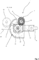
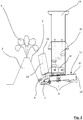
- FIG Figures 1 to 4 show, in different views, a device 1 for mowing vegetation between dams 2, as shown in FIG Figures 2 and 3 are indicated. Between the dams 2 and on the flanks 3 of the dams 2, vegetation (not shown in more detail) unfolds, which over time covers the flanks 3 of the dams 2, so that the dam culture with its plants 4 can be damaged.
- the dams 2 are covered with a film, also not shown in detail.
- the device 1 can be designed as a unit with its own wheels or movable on a carrier vehicle, not shown in detail. By means of the latter, the device 1 can be moved in a direction of movement 26 along the dams 2.
- the device 1 comprises a mowing unit 5, which as such on the flank 3 of the dam 2 at least by a guide wheel 15, shown in the Figures 1 , 3 and 4th , is guided at a defined distance from flank 3.
- the mower unit 5, as shown in the illustration of Figure 1 can be seen in the plan view, comprises a first rotating element 7 and a second rotating element 8, which cooperates with the first rotating element 7 resting on a surface of the flank 3.
- first rotating element 7 comprises a round brush
- second rotating element 8 comprising a knife
- first rotating element 7 in its arrangement or in its position with its bristles 9 sweeping over the partial area 10 of the second rotating element 8.
- Axes of rotation 22, 23 of the two rotating elements 7, 8 are here arranged at a distance from one another and are skewed to one another.
- the second rotating element 8 is arranged in a housing 12 provided with a partial opening 11.
- the housing 12 is cup-shaped here and comprises an upper cover 21 and an edge-side collar 25.
- the first rotating element 7 engages with its bristles 9, which are arranged equidistantly here, into the partial opening 11 of the knife housing 12, the partial opening here being in the form of an edge cutout 24 in the cover 21 of the housing 12.
- the second rotating element 8 can consist of a cutting disk on which a knife is pivotably mounted.
- the device 1 is designed with a movable frame 13. It can also be seen that the lateral guide wheel 15 can be adjusted and fixed in an angular position via fastening elements 14. There is thus the possibility of adapting the mowing unit 5 in accordance with an inclination of the surface of the flank 3 of the respective dam 2, so that brushing perpendicular to the surface of the flank 3 can always take place by means of the first rotating element 7.
- a guide wheel 15 pointing towards the surface of the flank 3 is provided on the frame 13 to limit a pressure depth of the first rotating element 7.
- the guide wheel 15 delimits in particular the flexible or soft bristles 9 of the first rotating element 7, so that they can brush off the growth from the film with their flexible end without damaging the film.
- a height guide wheel 6 for the mower unit 5 is provided on the frame 13.
- the height guide wheel 6 in particular is responsible for the fact that the cutting horizon is specified in the intermediate dam area.
- the compensating joint 16 here comprises pivotably mounted tie rods 17 or push rods 18 which are arranged in parallel and which in particular define a vertical adjustment range within which the mower unit 5 can move up and down.
- first rotating element 7 and the second rotating element 8 each have a motor drive 19, 20.
Landscapes
- Life Sciences & Earth Sciences (AREA)
- Environmental Sciences (AREA)
- Harvester Elements (AREA)
Applications Claiming Priority (1)
| Application Number | Priority Date | Filing Date | Title |
|---|---|---|---|
| DE202020102192.3U DE202020102192U1 (de) | 2020-04-21 | 2020-04-21 | Vorrichtung zum Mähen von Bewuchs zwischen Dämmen und an den Flanken von Dämmen |
Publications (2)
| Publication Number | Publication Date |
|---|---|
| EP3900516A1 true EP3900516A1 (fr) | 2021-10-27 |
| EP3900516B1 EP3900516B1 (fr) | 2023-08-09 |
Family
ID=75896721
Family Applications (1)
| Application Number | Title | Priority Date | Filing Date |
|---|---|---|---|
| EP21169288.4A Active EP3900516B1 (fr) | 2020-04-21 | 2021-04-20 | Dispositif de fauchage de couverture végétale entre barrages et sur les flancs des barrages |
Country Status (3)
| Country | Link |
|---|---|
| EP (1) | EP3900516B1 (fr) |
| DE (1) | DE202020102192U1 (fr) |
| PL (1) | PL3900516T3 (fr) |
Families Citing this family (1)
| Publication number | Priority date | Publication date | Assignee | Title |
|---|---|---|---|---|
| AT527605B1 (de) | 2024-01-09 | 2025-04-15 | Teufl Gmbh | Vorrichtung zur unkrautbekämpfung |
Citations (6)
| Publication number | Priority date | Publication date | Assignee | Title |
|---|---|---|---|---|
| DE4136327A1 (de) | 1991-11-05 | 1993-05-06 | Maschinenfabrik Bermatingen Gmbh & Co, 7775 Bermatingen, De | Landwirtschaftliche maschine |
| DE9404150U1 (de) * | 1994-03-11 | 1994-05-11 | Jauß, Paul, 82069 Hohenschäftlarn | Sichelmähvorrichtung |
| DE4323627C1 (de) * | 1993-07-15 | 1995-01-12 | Bermatingen Maschf | Landwirtschaftliche Maschine |
| US5435118A (en) * | 1994-05-12 | 1995-07-25 | Cobile; Alfredo P. | Vacuum sweeper shredder rotary mower |
| US7877971B1 (en) * | 2003-04-01 | 2011-02-01 | Department Of Veterans Affairs | Mower trimmer combination for facilitating simultaneous mowing and edge trimming in a single pass |
| US10631461B1 (en) * | 2016-03-14 | 2020-04-28 | Andros Engineering | Device and system for extracting and densifying agricultural plastics |
Family Cites Families (2)
| Publication number | Priority date | Publication date | Assignee | Title |
|---|---|---|---|---|
| US5303532A (en) * | 1992-07-28 | 1994-04-19 | Phillips Barry L | Mower support apparatus and system |
| US10136579B2 (en) * | 2017-01-20 | 2018-11-27 | David D. Button | Mower for attachment to an agricultural vehicle |
-
2020
- 2020-04-21 DE DE202020102192.3U patent/DE202020102192U1/de active Active
-
2021
- 2021-04-20 EP EP21169288.4A patent/EP3900516B1/fr active Active
- 2021-04-20 PL PL21169288.4T patent/PL3900516T3/pl unknown
Patent Citations (6)
| Publication number | Priority date | Publication date | Assignee | Title |
|---|---|---|---|---|
| DE4136327A1 (de) | 1991-11-05 | 1993-05-06 | Maschinenfabrik Bermatingen Gmbh & Co, 7775 Bermatingen, De | Landwirtschaftliche maschine |
| DE4323627C1 (de) * | 1993-07-15 | 1995-01-12 | Bermatingen Maschf | Landwirtschaftliche Maschine |
| DE9404150U1 (de) * | 1994-03-11 | 1994-05-11 | Jauß, Paul, 82069 Hohenschäftlarn | Sichelmähvorrichtung |
| US5435118A (en) * | 1994-05-12 | 1995-07-25 | Cobile; Alfredo P. | Vacuum sweeper shredder rotary mower |
| US7877971B1 (en) * | 2003-04-01 | 2011-02-01 | Department Of Veterans Affairs | Mower trimmer combination for facilitating simultaneous mowing and edge trimming in a single pass |
| US10631461B1 (en) * | 2016-03-14 | 2020-04-28 | Andros Engineering | Device and system for extracting and densifying agricultural plastics |
Also Published As
| Publication number | Publication date |
|---|---|
| PL3900516T3 (pl) | 2023-12-27 |
| EP3900516B1 (fr) | 2023-08-09 |
| DE202020102192U1 (de) | 2021-04-22 |
Similar Documents
| Publication | Publication Date | Title |
|---|---|---|
| EP3804484B1 (fr) | Dispositif d'entretien des plantes cultivées en rangées et des vignes | |
| DE60013240T2 (de) | Mehrzweckmaschine zum Zwischenkultivieren für Baum- oder Strauchpflanzungen bzw. Wein- oder Obstgärten | |
| EP3162183A1 (fr) | Dispositif de tonte ou de mulching | |
| DE1457690A1 (de) | Garten- und Ackerbaugeraet | |
| DE202013105582U1 (de) | Landwirtschaftliches Gerät | |
| DE7135965U (de) | Bodenbearbeitungsmaschine | |
| EP0487968B1 (fr) | Dispositif de labourage du sol | |
| DE102021200019B3 (de) | Mähvorrichtung zum mähen von zwischenräumen zwischen spalierreihen von kulturpflanzen | |
| EP3873206A1 (fr) | Lutte contre des plantes faisant appel à l'énergie électrique | |
| EP3900516B1 (fr) | Dispositif de fauchage de couverture végétale entre barrages et sur les flancs des barrages | |
| EP2092816B1 (fr) | Tête de paillage | |
| WO2023104245A1 (fr) | Unité porte-outil pour dispositif de travail du sol, dispositif de travail du sol et procédé de fonctionnement de dispositif de travail du sol | |
| EP0182122A1 (fr) | Faucheuse | |
| DE102010006506A1 (de) | Vorrichtung und Verfahren zum Ernten von eng am Boden wachsenden Pflanzen | |
| DE102010043317A1 (de) | Mäh-Hackvorrichtung zur Ernte großwüchsiger Pflanzen | |
| DE4136327A1 (de) | Landwirtschaftliche maschine | |
| DE4302198C2 (de) | Verfahren und Gerät zur Unkrautbekämpfung bei Kulturpflanzen, insbesondere Mais | |
| EP3031313A1 (fr) | Dispositif de separation de fanes | |
| EP1785028B1 (fr) | Appareil de coupe pour séparer les stolons ou des parties de plantes | |
| DE102011008938B4 (de) | Laubschneider für Weinstöcke | |
| EP1507451A2 (fr) | Dispositif pour moissonner des plantes | |
| DE202005009008U1 (de) | Mulchgerät | |
| DE102009006045A1 (de) | Mulch- und/oder Mähmaschine | |
| WO1993011659A1 (fr) | Tondeuse aspiratrice a generateur de courant d'air d'aspiration | |
| DE7504816U (de) | Messerwelle für Schlegelmulchgeräte |
Legal Events
| Date | Code | Title | Description |
|---|---|---|---|
| PUAI | Public reference made under article 153(3) epc to a published international application that has entered the european phase |
Free format text: ORIGINAL CODE: 0009012 |
|
| STAA | Information on the status of an ep patent application or granted ep patent |
Free format text: STATUS: THE APPLICATION HAS BEEN PUBLISHED |
|
| AK | Designated contracting states |
Kind code of ref document: A1 Designated state(s): AL AT BE BG CH CY CZ DE DK EE ES FI FR GB GR HR HU IE IS IT LI LT LU LV MC MK MT NL NO PL PT RO RS SE SI SK SM TR |
|
| B565 | Issuance of search results under rule 164(2) epc |
Effective date: 20210916 |
|
| STAA | Information on the status of an ep patent application or granted ep patent |
Free format text: STATUS: REQUEST FOR EXAMINATION WAS MADE |
|
| 17P | Request for examination filed |
Effective date: 20211026 |
|
| RBV | Designated contracting states (corrected) |
Designated state(s): AL AT BE BG CH CY CZ DE DK EE ES FI FR GB GR HR HU IE IS IT LI LT LU LV MC MK MT NL NO PL PT RO RS SE SI SK SM TR |
|
| GRAP | Despatch of communication of intention to grant a patent |
Free format text: ORIGINAL CODE: EPIDOSNIGR1 |
|
| STAA | Information on the status of an ep patent application or granted ep patent |
Free format text: STATUS: GRANT OF PATENT IS INTENDED |
|
| INTG | Intention to grant announced |
Effective date: 20230320 |
|
| GRAS | Grant fee paid |
Free format text: ORIGINAL CODE: EPIDOSNIGR3 |
|
| GRAA | (expected) grant |
Free format text: ORIGINAL CODE: 0009210 |
|
| STAA | Information on the status of an ep patent application or granted ep patent |
Free format text: STATUS: THE PATENT HAS BEEN GRANTED |
|
| AK | Designated contracting states |
Kind code of ref document: B1 Designated state(s): AL AT BE BG CH CY CZ DE DK EE ES FI FR GB GR HR HU IE IS IT LI LT LU LV MC MK MT NL NO PL PT RO RS SE SI SK SM TR |
|
| REG | Reference to a national code |
Ref country code: GB Ref legal event code: FG4D Free format text: NOT ENGLISH |
|
| REG | Reference to a national code |
Ref country code: CH Ref legal event code: EP |
|
| REG | Reference to a national code |
Ref country code: DE Ref legal event code: R096 Ref document number: 502021001180 Country of ref document: DE |
|
| REG | Reference to a national code |
Ref country code: IE Ref legal event code: FG4D Free format text: LANGUAGE OF EP DOCUMENT: GERMAN |
|
| P01 | Opt-out of the competence of the unified patent court (upc) registered |
Effective date: 20230807 |
|
| REG | Reference to a national code |
Ref country code: LT Ref legal event code: MG9D |
|
| REG | Reference to a national code |
Ref country code: NL Ref legal event code: MP Effective date: 20230809 |
|
| PG25 | Lapsed in a contracting state [announced via postgrant information from national office to epo] |
Ref country code: GR Free format text: LAPSE BECAUSE OF FAILURE TO SUBMIT A TRANSLATION OF THE DESCRIPTION OR TO PAY THE FEE WITHIN THE PRESCRIBED TIME-LIMIT Effective date: 20231110 |
|
| PG25 | Lapsed in a contracting state [announced via postgrant information from national office to epo] |
Ref country code: IS Free format text: LAPSE BECAUSE OF FAILURE TO SUBMIT A TRANSLATION OF THE DESCRIPTION OR TO PAY THE FEE WITHIN THE PRESCRIBED TIME-LIMIT Effective date: 20231209 |
|
| PG25 | Lapsed in a contracting state [announced via postgrant information from national office to epo] |
Ref country code: SE Free format text: LAPSE BECAUSE OF FAILURE TO SUBMIT A TRANSLATION OF THE DESCRIPTION OR TO PAY THE FEE WITHIN THE PRESCRIBED TIME-LIMIT Effective date: 20230809 Ref country code: RS Free format text: LAPSE BECAUSE OF FAILURE TO SUBMIT A TRANSLATION OF THE DESCRIPTION OR TO PAY THE FEE WITHIN THE PRESCRIBED TIME-LIMIT Effective date: 20230809 Ref country code: PT Free format text: LAPSE BECAUSE OF FAILURE TO SUBMIT A TRANSLATION OF THE DESCRIPTION OR TO PAY THE FEE WITHIN THE PRESCRIBED TIME-LIMIT Effective date: 20231211 Ref country code: NO Free format text: LAPSE BECAUSE OF FAILURE TO SUBMIT A TRANSLATION OF THE DESCRIPTION OR TO PAY THE FEE WITHIN THE PRESCRIBED TIME-LIMIT Effective date: 20231109 Ref country code: NL Free format text: LAPSE BECAUSE OF FAILURE TO SUBMIT A TRANSLATION OF THE DESCRIPTION OR TO PAY THE FEE WITHIN THE PRESCRIBED TIME-LIMIT Effective date: 20230809 Ref country code: LV Free format text: LAPSE BECAUSE OF FAILURE TO SUBMIT A TRANSLATION OF THE DESCRIPTION OR TO PAY THE FEE WITHIN THE PRESCRIBED TIME-LIMIT Effective date: 20230809 Ref country code: LT Free format text: LAPSE BECAUSE OF FAILURE TO SUBMIT A TRANSLATION OF THE DESCRIPTION OR TO PAY THE FEE WITHIN THE PRESCRIBED TIME-LIMIT Effective date: 20230809 Ref country code: IS Free format text: LAPSE BECAUSE OF FAILURE TO SUBMIT A TRANSLATION OF THE DESCRIPTION OR TO PAY THE FEE WITHIN THE PRESCRIBED TIME-LIMIT Effective date: 20231209 Ref country code: HR Free format text: LAPSE BECAUSE OF FAILURE TO SUBMIT A TRANSLATION OF THE DESCRIPTION OR TO PAY THE FEE WITHIN THE PRESCRIBED TIME-LIMIT Effective date: 20230809 Ref country code: GR Free format text: LAPSE BECAUSE OF FAILURE TO SUBMIT A TRANSLATION OF THE DESCRIPTION OR TO PAY THE FEE WITHIN THE PRESCRIBED TIME-LIMIT Effective date: 20231110 Ref country code: FI Free format text: LAPSE BECAUSE OF FAILURE TO SUBMIT A TRANSLATION OF THE DESCRIPTION OR TO PAY THE FEE WITHIN THE PRESCRIBED TIME-LIMIT Effective date: 20230809 |
|
| PG25 | Lapsed in a contracting state [announced via postgrant information from national office to epo] |
Ref country code: ES Free format text: LAPSE BECAUSE OF FAILURE TO SUBMIT A TRANSLATION OF THE DESCRIPTION OR TO PAY THE FEE WITHIN THE PRESCRIBED TIME-LIMIT Effective date: 20230809 |
|
| PG25 | Lapsed in a contracting state [announced via postgrant information from national office to epo] |
Ref country code: SM Free format text: LAPSE BECAUSE OF FAILURE TO SUBMIT A TRANSLATION OF THE DESCRIPTION OR TO PAY THE FEE WITHIN THE PRESCRIBED TIME-LIMIT Effective date: 20230809 Ref country code: RO Free format text: LAPSE BECAUSE OF FAILURE TO SUBMIT A TRANSLATION OF THE DESCRIPTION OR TO PAY THE FEE WITHIN THE PRESCRIBED TIME-LIMIT Effective date: 20230809 Ref country code: ES Free format text: LAPSE BECAUSE OF FAILURE TO SUBMIT A TRANSLATION OF THE DESCRIPTION OR TO PAY THE FEE WITHIN THE PRESCRIBED TIME-LIMIT Effective date: 20230809 Ref country code: EE Free format text: LAPSE BECAUSE OF FAILURE TO SUBMIT A TRANSLATION OF THE DESCRIPTION OR TO PAY THE FEE WITHIN THE PRESCRIBED TIME-LIMIT Effective date: 20230809 Ref country code: DK Free format text: LAPSE BECAUSE OF FAILURE TO SUBMIT A TRANSLATION OF THE DESCRIPTION OR TO PAY THE FEE WITHIN THE PRESCRIBED TIME-LIMIT Effective date: 20230809 Ref country code: CZ Free format text: LAPSE BECAUSE OF FAILURE TO SUBMIT A TRANSLATION OF THE DESCRIPTION OR TO PAY THE FEE WITHIN THE PRESCRIBED TIME-LIMIT Effective date: 20230809 Ref country code: SK Free format text: LAPSE BECAUSE OF FAILURE TO SUBMIT A TRANSLATION OF THE DESCRIPTION OR TO PAY THE FEE WITHIN THE PRESCRIBED TIME-LIMIT Effective date: 20230809 |
|
| REG | Reference to a national code |
Ref country code: DE Ref legal event code: R097 Ref document number: 502021001180 Country of ref document: DE |
|
| PG25 | Lapsed in a contracting state [announced via postgrant information from national office to epo] |
Ref country code: IT Free format text: LAPSE BECAUSE OF FAILURE TO SUBMIT A TRANSLATION OF THE DESCRIPTION OR TO PAY THE FEE WITHIN THE PRESCRIBED TIME-LIMIT Effective date: 20230809 |
|
| PLBE | No opposition filed within time limit |
Free format text: ORIGINAL CODE: 0009261 |
|
| STAA | Information on the status of an ep patent application or granted ep patent |
Free format text: STATUS: NO OPPOSITION FILED WITHIN TIME LIMIT |
|
| 26N | No opposition filed |
Effective date: 20240513 |
|
| PG25 | Lapsed in a contracting state [announced via postgrant information from national office to epo] |
Ref country code: SI Free format text: LAPSE BECAUSE OF FAILURE TO SUBMIT A TRANSLATION OF THE DESCRIPTION OR TO PAY THE FEE WITHIN THE PRESCRIBED TIME-LIMIT Effective date: 20230809 |
|
| PG25 | Lapsed in a contracting state [announced via postgrant information from national office to epo] |
Ref country code: BG Free format text: LAPSE BECAUSE OF FAILURE TO SUBMIT A TRANSLATION OF THE DESCRIPTION OR TO PAY THE FEE WITHIN THE PRESCRIBED TIME-LIMIT Effective date: 20230809 |
|
| PG25 | Lapsed in a contracting state [announced via postgrant information from national office to epo] |
Ref country code: MC Free format text: LAPSE BECAUSE OF FAILURE TO SUBMIT A TRANSLATION OF THE DESCRIPTION OR TO PAY THE FEE WITHIN THE PRESCRIBED TIME-LIMIT Effective date: 20230809 |
|
| PG25 | Lapsed in a contracting state [announced via postgrant information from national office to epo] |
Ref country code: MC Free format text: LAPSE BECAUSE OF FAILURE TO SUBMIT A TRANSLATION OF THE DESCRIPTION OR TO PAY THE FEE WITHIN THE PRESCRIBED TIME-LIMIT Effective date: 20230809 Ref country code: BG Free format text: LAPSE BECAUSE OF FAILURE TO SUBMIT A TRANSLATION OF THE DESCRIPTION OR TO PAY THE FEE WITHIN THE PRESCRIBED TIME-LIMIT Effective date: 20230809 |
|
| REG | Reference to a national code |
Ref country code: CH Ref legal event code: PL |
|
| PG25 | Lapsed in a contracting state [announced via postgrant information from national office to epo] |
Ref country code: LU Free format text: LAPSE BECAUSE OF NON-PAYMENT OF DUE FEES Effective date: 20240420 |
|
| REG | Reference to a national code |
Ref country code: BE Ref legal event code: MM Effective date: 20240430 |
|
| PG25 | Lapsed in a contracting state [announced via postgrant information from national office to epo] |
Ref country code: LU Free format text: LAPSE BECAUSE OF NON-PAYMENT OF DUE FEES Effective date: 20240420 |
|
| PG25 | Lapsed in a contracting state [announced via postgrant information from national office to epo] |
Ref country code: BE Free format text: LAPSE BECAUSE OF NON-PAYMENT OF DUE FEES Effective date: 20240430 |
|
| PG25 | Lapsed in a contracting state [announced via postgrant information from national office to epo] |
Ref country code: BE Free format text: LAPSE BECAUSE OF NON-PAYMENT OF DUE FEES Effective date: 20240430 Ref country code: CH Free format text: LAPSE BECAUSE OF NON-PAYMENT OF DUE FEES Effective date: 20240430 |
|
| PG25 | Lapsed in a contracting state [announced via postgrant information from national office to epo] |
Ref country code: IE Free format text: LAPSE BECAUSE OF NON-PAYMENT OF DUE FEES Effective date: 20240420 |
|
| PG25 | Lapsed in a contracting state [announced via postgrant information from national office to epo] |
Ref country code: CY Free format text: LAPSE BECAUSE OF FAILURE TO SUBMIT A TRANSLATION OF THE DESCRIPTION OR TO PAY THE FEE WITHIN THE PRESCRIBED TIME-LIMIT; INVALID AB INITIO Effective date: 20210420 |
|
| PG25 | Lapsed in a contracting state [announced via postgrant information from national office to epo] |
Ref country code: HU Free format text: LAPSE BECAUSE OF FAILURE TO SUBMIT A TRANSLATION OF THE DESCRIPTION OR TO PAY THE FEE WITHIN THE PRESCRIBED TIME-LIMIT; INVALID AB INITIO Effective date: 20210420 |
|
| GBPC | Gb: european patent ceased through non-payment of renewal fee |
Effective date: 20250420 |
|
| PG25 | Lapsed in a contracting state [announced via postgrant information from national office to epo] |
Ref country code: GB Free format text: LAPSE BECAUSE OF NON-PAYMENT OF DUE FEES Effective date: 20250420 |
|
| PGFP | Annual fee paid to national office [announced via postgrant information from national office to epo] |
Ref country code: PL Payment date: 20260324 Year of fee payment: 6 |
|
| PG25 | Lapsed in a contracting state [announced via postgrant information from national office to epo] |
Ref country code: TR Free format text: LAPSE BECAUSE OF FAILURE TO SUBMIT A TRANSLATION OF THE DESCRIPTION OR TO PAY THE FEE WITHIN THE PRESCRIBED TIME-LIMIT Effective date: 20230809 |
|
| PGFP | Annual fee paid to national office [announced via postgrant information from national office to epo] |
Ref country code: DE Payment date: 20260430 Year of fee payment: 6 |
|
| PGFP | Annual fee paid to national office [announced via postgrant information from national office to epo] |
Ref country code: AT Payment date: 20260416 Year of fee payment: 6 |
|
| PGFP | Annual fee paid to national office [announced via postgrant information from national office to epo] |
Ref country code: FR Payment date: 20260423 Year of fee payment: 6 |