EP3900527A1 - Procédé d'alimentation d'animaux et installation pneumatique d'alimentation - Google Patents
Procédé d'alimentation d'animaux et installation pneumatique d'alimentation Download PDFInfo
- Publication number
- EP3900527A1 EP3900527A1 EP21169889.9A EP21169889A EP3900527A1 EP 3900527 A1 EP3900527 A1 EP 3900527A1 EP 21169889 A EP21169889 A EP 21169889A EP 3900527 A1 EP3900527 A1 EP 3900527A1
- Authority
- EP
- European Patent Office
- Prior art keywords
- feed
- feeding
- feed line
- air
- line system
- Prior art date
- Legal status (The legal status is an assumption and is not a legal conclusion. Google has not performed a legal analysis and makes no representation as to the accuracy of the status listed.)
- Pending
Links
Images
Classifications
-
- A—HUMAN NECESSITIES
- A01—AGRICULTURE; FORESTRY; ANIMAL HUSBANDRY; HUNTING; TRAPPING; FISHING
- A01K—ANIMAL HUSBANDRY; AVICULTURE; APICULTURE; PISCICULTURE; FISHING; REARING OR BREEDING ANIMALS, NOT OTHERWISE PROVIDED FOR; NEW BREEDS OF ANIMALS
- A01K5/00—Feeding devices for stock or game ; Feeding wagons; Feeding stacks
- A01K5/02—Automatic devices
- A01K5/0275—Automatic devices with mechanisms for delivery of measured doses
-
- A—HUMAN NECESSITIES
- A01—AGRICULTURE; FORESTRY; ANIMAL HUSBANDRY; HUNTING; TRAPPING; FISHING
- A01K—ANIMAL HUSBANDRY; AVICULTURE; APICULTURE; PISCICULTURE; FISHING; REARING OR BREEDING ANIMALS, NOT OTHERWISE PROVIDED FOR; NEW BREEDS OF ANIMALS
- A01K5/00—Feeding devices for stock or game ; Feeding wagons; Feeding stacks
- A01K5/02—Automatic devices
Definitions
- the invention relates to a method for feeding animals by means of a pneumatic feeding system and a feeding system for the preparation and pneumatic distribution of animal feed.
- compressed air is used to convey portions of animal feed.
- the animal feed can, for example, be provided in a storage container or an animal feed mixture can be prepared by means of a mixing device, for example a batch mixer.
- a mixing device for example a batch mixer.
- an animal feed mixture is portioned into feed portions one after the other, released into a feed pipe system and conveyed to feeding points for the animals by means of the compressed air.
- Generic, pneumatic feeding systems and methods are, for example, from the EP 2 977 340 A1 or EP 2 502 489 B1 known.
- pneumatic feeding systems or methods offer some advantages over alternative feeding methods, such as hydraulic feeding methods and systems.
- animal feed mixtures with pneumatic feeding can be individually adapted and portioned for different animals relatively easily.
- phase feeding i.e. feeding adapted to the development phase of the respective animal
- feed portions of various consistencies from liquid to moistened to dry, can be administered.
- pneumatic feeding systems can be operated very flexibly, so that, for example, any fluctuations in feed prices can be taken into account with regard to animal feeding that is as economical as possible.
- pneumatic feeding systems are increasingly in demand in animal husbandry and are being used in ever increasing numbers.
- the object of the invention was therefore to provide a method for feeding animals by means of a pneumatic feeding system which enables animal feeding to be improved in terms of efficiency and flexibility compared to the prior art.
- a further object of the invention was to provide a pneumatic feeding system that can be used as efficiently and flexibly as possible.
- At at least one measuring point in the course or along the feed line system transitions from air to a respective feed portion and / or transitions from a respective feed portion to air at the at least one measuring point in the feed line system by means of at least one sensor connected to the control device can be detected.
- the point in time at which a respective feed portion passes or has passed the sensor (s) can be determined to be determined.
- reference points detected by sensors can be provided in particular for the control device and, based on these reference points, the control of the pneumatic feeding system, in particular the timing of the feeding system, can be carried out with improved efficiency.
- the detection of the transitions from air to a feed portion or from a feed portion to air provides sufficiently precise reference points for these control-related processes of the method, or the control-related processes can be carried out with sufficient accuracy.
- blowing times for conveying the feed portions in the feed line system can be controlled automatically on the basis of the detected transitions.
- Reserves or reserve blowing times, which were necessary in previously known pneumatic methods in order to ensure complete dispensing of the feed portions can at least largely be minimized or even made superfluous.
- the feeding speed in particular can subsequently be increased, and thus the efficiency of the method can be improved.
- animal feed mixtures which have very different conveying properties or which require different conveying times due to different compositions and thus different densities and / or consistencies can nevertheless be used in direct succession to feed the animals or conveyed through the feed line system without special adaptations being necessary here .
- the sensor-based detection of the transition from air to feed portions or vice versa enables the time required for complete delivery to feed points to be determined automatically and the blowing times to be adjusted accordingly.
- the wear of the system components can also be further reduced, since the application of compressed air to the feed line system, which causes wear, can be minimized in terms of time.
- the feeding of the feed portions from the mixing and / or storage container into the at least one main feed line can take place sequentially in the pneumatically operated method for animal feeding, so that the individual feed portions provided for a feeding point are conveyed sequentially in the feed line system.
- it can be provided that in each case only this feed portion is located in the feed line system until the final, complete delivery of a feed portion.
- several feed portions can also be conveyed in the feed line system at the same time, with the feeding of the respective feed portions into the feed line system in turn being able to be carried out one after the other.
- a simple storage container or several storage containers which can be filled with animal feed mixtures can be provided.
- a storage container can also be provided, which is supplied with freshly prepared animal feed mixture from a separate mixing container in which an animal feed mixture is prepared.
- several storage and mixing containers can of course also be provided for this purpose.
- an animal feed mixture or animal feed mixtures can of course also be introduced directly into the feed line system from one or more mixing container (s), which serve as storage containers at the same time, without intermediate storage containers.
- a metering device must be provided for portioning and feeding in portions of animal feed from a mixing and / or storage container.
- a metering device can in principle be formed by any suitable feed sluice.
- suitable feed sluice For example, chamber locks, rotary locks, but also simple, in particular powered, open / close flaps can be used as metering devices.
- the selection of the type of metering device or feed sluice can be made quite generally according to the type of feed mixture (s) which are prepared or temporarily stored in the associated mixing and / or storage container.
- a compressor or fan for example, can be provided in a manner known per se.
- any devices by means of which a switchover to the individual feed or feeding point feed lines can be implemented can be used as the distribution means.
- suitable valve or distribution devices can be used, so-called rotary distributors have particularly proven themselves in practice.
- the detection of the transitions from air to a respective feed portion or from a respective feed portion to air can basically be carried out at one or more, arbitrary measuring point (s) in the course of or along the feed line system.
- a single sensor arranged in the course of the main feed line can be sufficient for this purpose.
- a calculation of the (remaining) running time of a feed portion in the feed line system, for example up to the complete delivery to a feeding point on the basis of a detected transition using further known parameters, such as the known line cross-sections of the feed line system and the known air pressures in the feed line system can be done with sufficient accuracy.
- Corresponding calculation algorithms can be mapped in the control device for the automatic control of the pneumatic feeding system.
- transitions from air to a respective feed portion or from a feed portion to air can of course also be detected at several measuring points in the course of the feed line system by means of several sensors.
- the detection accuracy and, subsequently, the efficiency of the operation of a feeding system can be further improved.
- certain variants of the arrangement of the measuring point (s) or sensor (s) have proven to be particularly advantageous in the method.
- the transitions from air to a respective feed portion and / or the transitions from a respective feed portion to air by means of at least one at at least one measuring point in the course of the main feed line or a feed line in front of the at least one distribution means arranged sensor is detected.
- a sensor can be arranged locally at a measuring point which is as close as possible to the distribution means in the course of the main feed line or in the course of a feed line.
- the feed portions or, if need be, all feed portions at a measuring point can be detected with a time offset using only one sensor, and thus locally constant time reference points for the control of the pneumatic feeding system can be obtained.
- fluctuating parameters for example due to feed portions with different consistencies, can be recorded and the control of the feeding system can be adjusted accordingly.
- a process management can be useful in which the transitions from air to a respective feed portion and / or the transitions from a respective feed portion to air by means of several at several measuring points in the course or along several feeding points are detected in front of several feeding points arranged sensors.
- the measuring accuracy of the determination of the transitions from air to a respective feed portion or from a respective feed portion to air can optionally be increased.
- the control of feeding processes which (in time) are specifically related to the delivery of feed portions to a respective feeding point, can be carried out with increased accuracy.
- an arrangement of a sensor or sensors along or in the course of a main feed line or a feed line can be dispensed with.
- the transitions in a main feed line or a feed line connected to it can also take place upstream of a distribution means in addition to the detection in the feeding lines after a distribution means.
- feeding processes related to the automatic animal feeding can be controlled in an improved manner, in particular in terms of time can be controlled better.
- Such an addition of water to the feed portions based on the detected transitions enables the most complete and homogeneous moistening of a feed portion to be achieved, since the addition of water can be switched on in good time at the start of a feed portion.
- water can be carried out automatically controlled by means of the control device on the basis of the detected transitions.
- water can be added at any point in the course of the feed pipe system, for example water can be added in the course of the main feed pipe or a feed pipe before a distribution means and / or in the course of feeding pipes.
- Feeding feed lines can be cleaned in an automated controlled manner as soon as possible after a portion of feed has passed through, and this can prevent, for example, the formation of feed residues in a feeding feed that is difficult to remove.
- feeding lines can be cleaned by means of drain cleaning devices arranged in the area of the feeding lines.
- feeding point feed lines or partial areas of the feed line system as a whole can be cleaned on the basis of detected transitions from feed portions to air by means of water addition devices provided for adding water to feed portions.
- the method can basically provide that, based on a detected transition from the feed portion to air, a new feed portion intended for a further feeding point is applied to the feed line system in a time-controlled manner.
- the time delay between the introduction of feed portions into the feed line system can be carried out very efficiently. Dead times due to otherwise to be provided safety tolerances or otherwise to be specified reserve time intervals for a secure complete delivery of a feed portion to a feeding point can be avoided or at least kept as short as possible by the specified measures.
- a further feed portion is introduced into the feed line system immediately after a complete delivery of a feed portion.
- further feed portions it is alternatively also possible for further feed portions to be staggered or successively fed into the feed line system when one or more feed portions are still in the feed line system or are still being conveyed to feeding points therein .
- a further feed portion is introduced into the feed line system, if necessary after a predeterminable reserve time interval has elapsed, before the detected feed portion is delivered to the associated feeding point.
- the feed line system is charged with a new feed portion intended for another feeding point after a predeterminable time interval has elapsed, and that on the basis of a detected transition from the feed portion to air, a distribution means to this is timed another feeding point is switched.
- the object of the invention is also achieved by a pneumatic feeding system.
- the pneumatic feeding system is provided for metering and distributing animal feed portions to several feeding or eating points, and can in particular be provided for carrying out the method described above.
- the pneumatic feeding system can be designed specifically for the automated, successive metering and distribution of animal feed portions to several feeding or eating points.
- the pneumatic feeding system comprises at least one mixing and / or storage container and a metering device for providing feed portions. Furthermore, the pneumatic feeding system comprises a feed line system for supplying the feed portions from the dosing device to the feeding or eating points, which feed line system comprises at least one main feed line connected to the dosing device and optionally further feed lines connected to the main feed line, and which feed line system includes several feed lines via at least one distribution means the main feed line or with one of the further feed lines connected and each opening into one of the feeding points comprises feeding point feed lines.
- the pneumatic feeding system comprises a compressed air generation device connected to the main feed line for the pneumatic conveyance of the feed portions via the feed line system, i.e. the main feed line, optionally the further feed lines and finally the feeding point feed lines to the feeding points, as well as one for controlling the dosage and conveying the feed portions to the feeding points trained control device.
- At least one sensor which is signal-connected to the control device, is arranged at at least one measuring point in the course of the feed line system, which at least one sensor metrologically for the detection of transitions from air to a respective feed portion and / or transitions from a respective feed portion to air at the at least one measuring point in the feed line system is formed.
- reference points that can be detected by sensors can be provided for the control device, based on which reference points the control of the pneumatic feeding system, in particular the timing of the feeding system, can be carried out with improved efficiency by the correspondingly designed control device.
- the sensors for detecting the transitions from air to a feed portion or from a feed portion to air provide sufficiently accurate reference points for the operation of the pneumatic feeding system, or the control processes can be carried out with sufficient accuracy by the control device.
- blowing times for conveying the feed portions in the feed line system are based of the detected transitions can be controlled automatically.
- Reserves or reserve blowing times which had to be set or provided in previously known pneumatic feeding systems in order to ensure complete dispensing of the feed portions in any case, can at least largely be minimized or even made superfluous.
- the specified features can in particular increase the feeding speed and thus improve the efficiency of the feeding system in operation.
- the pneumatic feeding system can also be operated more flexibly in this context.
- animal feed mixtures which have very different conveying properties or require different conveying times due to different compositions and thus different densities and / or consistencies can nevertheless be used in direct succession to feed the animals or conveyed through the feed line system.
- the sensor-based detection of the transitions from air to feed portions and vice versa can automatically determine the time required for complete delivery to feeding places, and the blowing times can be adjusted accordingly or controlled by the control device.
- the wear of system components can also be further reduced, since the application of compressed air to the feed line system, which causes wear, can be minimized in terms of time.
- a simple storage container can be provided for receiving a supply amount of the animal feed.
- a storage container connected to a separate mixing container in which an animal feed mixture can be freshly prepared can also be provided.
- a mixing container can of course also be connected directly to the feed line system via the metering device.
- one mixing and / or storage container may be sufficient, but several mixing and / or storage containers can of course also be provided .
- the metering device for portioning and channeling the feed portions into the feed line system can be formed by any suitable feed sluice. So can for
- Example chamber locks, rotary valves but also simple, in particular driven open / close flaps can be selected as the metering device.
- the selection of the type of metering device or feed sluice can be made quite generally according to the type of feed mixture (s) which are prepared or temporarily stored in the associated mixing and / or storage container.
- the compressed air generating device can be formed, for example, by a compressor or a fan.
- the distribution means (s) can be formed by any device by means of which a switchover to the individual feeding or feeding point feed lines can be achieved.
- valve or distribution devices are suitable, so-called rotary distributors having proven particularly useful in practice.
- the at least one sensor for detecting the transitions from air to a feed portion or from a feed portion to air can basically be arranged at any measuring point in the course or along the feed line system.
- a single sensor arranged in the course of the main feed line can be sufficient. This is because a calculation of the (remaining) running time of a feed portion in the feed line system, for example up to the complete delivery to a feeding point, on the basis of a detected transition using further known parameters, such as the known line cross-sections of the feed line system and the known air pressures in the feed line system can be done with sufficient accuracy.
- Corresponding calculation algorithms can be mapped in the control device for the automatic control of the pneumatic feeding system.
- the at least one sensor is arranged at at least one measuring point in the course of the main feed line or a feed line in front of the at least one distribution means.
- a sensor can be arranged locally at a measuring point which is as close as possible to the distribution means in the course of the main feed line or a feed line.
- these features can be used to detect the feed portions or, if need be, all feed portions at a measuring point, and thus locally fixed time reference points can be provided for the control device. In this way, fluctuating parameters, for example due to feed portions with different consistencies, can also be recorded and adjusted accordingly by the control device of the feeding system.
- several sensors can also be arranged at several measuring points in the course of or along several feeding point feed lines in front of several feeding points.
- the measuring accuracy of the determination of the transitions from air to a respective feed portion or from a respective feed portion to air can be increased as a result.
- the control of feeding processes which are (in terms of time) specifically related to the delivery of feed portions to a respective feeding point, can be carried out with increased accuracy through such a process management.
- Such sensors arranged in the course of feeding point feed lines can be provided instead of one or more sensors in the course of the main feed line or in the course of a feed line, but at least one sensor can also be additionally arranged in the course or along the main feed line and / or in the course of a feed line.
- the at least one sensor for detecting the transitions from air to a respective feed portion or from a feed portion to air can in principle be formed by any sensor suitable for detecting these transitions.
- a mechanically operating sensor with a measuring extension arranged inside a main feed line and / or feed lines and / or feeding point supply line, adjustable by a feed portion is conceivable, which sensor converts an adjustment of such a measuring extension into an electronic signal and transmits the same to the control device.
- the at least one sensor can be formed by an optical detection device.
- the at least one sensor can in particular be formed by a light barrier sensor device.
- the particular advantage here is an improved detection accuracy in the operation of the feeding system and the longer service life or shorter maintenance intervals for sensors of this type.
- a pneumatic feeding system can be designed in such a way that at least one water addition device is arranged in the course of the feed line system, and that the control device based on a detected transition from air to a feed portion for the time-controlled addition of water to this feed portion by means of the at least one Water addition device is formed.
- control device is designed on the basis of a detected transition from the feed portion to air to stop the addition of water to this feed portion in a timed manner.
- a water addition device can be arranged at any point in the course of the feed line system, for example a water addition device can be arranged in the course of the main feed line or in the course of feed lines in front of a distribution means and / or in the course of feeding lines.
- a water addition device can for example by a fresh water supply line can be formed with a controllable open / close valve or a controllable pump, or be formed by a supply line from a water reservoir with a controllable valve or controllable pump.
- control device is designed on the basis of a detected transition from a feed portion to air for the time-controlled cleaning of feeding point feed lines.
- a drain cleaning device arranged in the area of the feeding lines can be provided for the purpose of cleaning feeding points.
- Such a drain cleaning device can be formed by any controllable cleaning device suitable for removing animal feed residues or impurities, such as a compressed air, rinsing, water jet device and the like.
- the control device can also be designed on the basis of detected transitions from feed portions to air for the time-controlled cleaning of feeding point feed lines, or also for cleaning partial areas of the feed line system by means of water addition devices provided for adding water to feed portions.
- control device can be designed on the basis of a detected transition from the feed portion to air for the time-controlled loading of the feed line system with a new feed portion intended for a further feeding point.
- the control device is based on the detected transitions is designed from one feed portion to air immediately after a complete delivery of a feed portion for introducing a further feed portion into the feed line system.
- control device can be designed for the staggered or successive introduction of further feed portions into the feed line system when one or more feed portions are still in or in the feed line system at the same time can still be promoted to feeding points.
- the control device is designed to feed a further feed portion into the feed line system before the detected feed portion is delivered to the associated feeding point is.
- a new feed portion intended for a further feeding point is applied to the feed line system, and that the control device closes on the basis of a detected transition from a feed portion Air is designed for the time-controlled switching of a distribution means to this further feeding point.
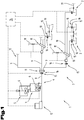
- FIG. 1 an exemplary embodiment of a generic, pneumatic feeding system 1 is shown in a greatly simplified manner.
- a pneumatic feeding system 1 is provided or suitable for metering and distribution, in particular for metering and distributing animal feed portions in succession in time.
- a plurality of feeding or eating points 2 can be provided here, to which feeding points 2 the animal feed portions are to be distributed or delivered.
- a pneumatic feeding system 1 comprises according to Fig. 1 for this purpose, at least one mixing and / or storage container 3 and a metering device 4 for providing feed portions.
- a storage container 3 connected to a separate mixing container 5 is provided so that an animal feed mixture can be prepared in the mixing container 5 and then fed to the storage container 3.
- Both the mixing container 5 and the storage container 3 are equipped with an agitator 6.
- a variant with only one storage container 3 is also conceivable, which is only provided for receiving an already finished animal feed mixture.
- an agitator 6 can also be dispensed with in the case of a storage container 3.
- a pneumatic feeding system 1 comprises a feed line system 7 for feeding the feed portions from the dosing device 4 to the feeding points 2.
- the dosing device 4 can pass through any device suitable for delivering a respectively desired amount of animal feed to the feed line system 7 can be formed, and can for example be a feed sluice that can be controlled accordingly include.
- a feed sluice that can be controlled accordingly include.
- chamber locks, rotary valves, but also simple, in particular driven, open / close flaps can be used as the metering device 4 in principle.
- the feed line system 7 comprises a main feed line 8 connected to the metering device 4 Fig. 1
- further feed lines 9 connected to the main feed line 8 can also be provided so that animal feed portions can be conveyed via such a branched feed line system 7 to different, spatially spaced apart areas of the feeding system 1 or, for example, an animal stable.
- the pneumatic feeding system 1 comprises several feeding point feed lines 10 each opening into one of the feeding points 2.
- any devices that can be used to switch to the individual feeding or feeding point feed lines can be used as the distribution means 11, such as on / off valves of various types proved particularly suitable.
- the distribution means 11 can of course also be used or provided in a pneumatic feeding system 1.
- a pneumatic feeding system 1 comprises as in FIG Fig. 1 shown is a compressed air generating device 12 connected to the main feed line 8 for the pneumatic conveyance of the feed portions via the feed line system 7 to the feeding points 2.
- a compressed air generating device 12 can be formed, for example, by a compressor or a fan.
- the pneumatic feeding system 1 shown by way of example is of course only to be regarded as a possible exemplary embodiment for a pneumatic feeding system 1.
- the number and arrangement of the feeding points 2 and therefore also the design of the feed line system 7 can vary depending on the respective requirements and from that in the Fig. 1 shown embodiment differ.
- a pneumatic feeding system 1 can of course also, as is known per se, comprise other feed lines 13 to various system components in addition to the feeding point feed lines 10, for example feed lines to collecting containers for feed residues or water residues, which, for example, after completion of animal feeding by blowing out or flushing the feed line system 7 or whose main feed line 8 and, if necessary, feed lines 9 can be directed or dispensed into such collecting containers.
- feed lines 13 to various system components in addition to the feeding point feed lines 10, for example feed lines to collecting containers for feed residues or water residues, which, for example, after completion of animal feeding by blowing out or flushing the feed line system 7 or whose main feed line 8 and, if necessary, feed lines 9 can be directed or dispensed into such collecting containers.
- Fig. 1 comprises a pneumatic feeding system 1 for controlling the metering and conveying of the feed portions to the feeding points 2
- control device 14 Fig. 1 at least the metering device 4 and compressed air generating device 12, as well as the distribution means 11, are signal-connected to this control device 14.
- the control device 14 can also be designed to control additional system components and can be signal-connected to such additional system components, as will be explained below.
- this at least one sensor 15 is metrologically designed to detect transitions from air to a respective feed portion 17 and / or transitions from a respective feed portion 17 to air at the at least one measuring point 16 in the feed line system 7.
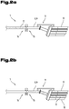
- This is for better visibility in the Figures 2a and 2b illustrates which show only part of a feed line system 7 in the area of a distribution means 15.
- Figures 2a and 2b The same reference numerals are used for the same components as in the preceding Fig. 1 . Further exemplary embodiments of a pneumatic feeding system 1 or a method for feeding animals by means of such a pneumatic animal feeding system 1 are also described below with reference to FIG Figures 2a and 2b explained in more detail.
- the procedure is based on the Fig. 1 , 2a and 2b recognizable at at least one measuring point 16 in the course of the feed pipe system 7 by means of at least one sensor 15 signal-connected to the control device 14 Transitions from air to a respective feed portion 17 and / or transitions from a respective feed portion 17 to air at the at least one measuring point 16 in the feed pipe system 7 detected.
- the at least one sensor 15 for detecting the transitions from air to a feed portion 17 or from a feed portion 17 to air can basically be arranged at any measuring point 16 in the course of or along the feed line system 7.
- a single sensor 15 arranged in the course of the main feed line 8 can be sufficient. This is because a calculation of the (remaining) runtime a feed portion 17 in the feed line system 7, for example up to the complete delivery to a feeding point 2, based on a detected transition by means of further known parameters, such as the known line cross-sections of the feed line system 7 and the known air pressures in the feed line system 7, can take place with sufficient accuracy.
- the transitions detected by means of the at least one sensor 15 each provide sufficiently accurate reference points for such calculations. Corresponding calculation algorithms can be mapped in the control device 14 for the automatic control of the pneumatic feeding system 1.
- the at least one sensor 15 can preferably be arranged at at least one measuring point 16 in the course of the main feed line 8 or a feed line 9 in front of the at least one distribution means 11.
- several sensors 15 can also be arranged at several measuring points 16 in the course of several feeding point feed lines 10 in front of several feeding points 2, as shown on the basis of this Fig. 1 is shown schematically.
- the at least one sensor 15 can preferably be formed by an optical detection device, particularly preferably by a light barrier sensor device.
- an optical detection device particularly preferably by a light barrier sensor device.
- other types of sensors for example electromechanical sensors, are also conceivable.
- the transitions from air to a respective feed portion 17 can be determined by means of at least one sensor 15 arranged at at least one measuring point 16 in the course of the main feed line 8 or a feed line 9 in front of the at least one distribution means 11, as in Fig. 2a can best be seen, and / or the transitions from a respective feed portion 17 to air, as best shown in FIG Figure 2b visible, can be detected.
- the transitions from air to a respective feed portion 17 and / or the transitions from a respective feed portion 17 to air can also be detected by means of several sensors 15 arranged at several measuring points 16 in the course of several feeding point feed lines 10 in front of several feeding points 2, like this in the Fig. 1 is shown. This either as an alternative or in addition to a detection of the transitions at one or more measuring points 16 in the course of the main feed line 8 or feed line 9.
- At least one water addition device 18 for adding water to a feed portion 17 can be arranged in the course of the feed line system 7. This in order to be able to provide improved food intake for the animals to be fed, for example.
- the control device 14 can subsequently on the basis of a detected transition from air to a feed portion 17, as shown in FIG Fig. 2a is illustrated, be designed for the time-controlled addition of water to this feed portion 17 by means of the at least one water addition device 18.
- control device 14 can on the basis of a detected transition from the feed portion 17 to air, see FIG Figure 2b , be designed to stop the addition of water to this feed portion 17 in a timed manner.
- a water addition device 18 can be arranged at any point in the course of the feed line system 7, for example a water addition device 18 can be arranged in the course of the main feed line 8 or in the course of feed lines 9 in front of a distribution means 11 and / or in the course of feeding lines 10 .
- a water addition device 18 can, for example, be provided by a fresh water supply line with a controllable open / close valve as in FIG Fig. 1 indicated, or be formed with a controllable pump.
- a supply of water from a water reservoir with a controllable valve or controllable pump is also possible.
- Can be particularly advantageous in connection with the moistening of animal feed portions 17 as in FIG Fig. 1 also be shown an arrangement of a water addition device 18 in front of a distribution means 11, as this means all Feed portions 17, which can be controlled or reached via this distribution means 11, water can be added.
- water can be added to this feed portion 17 in a time-controlled manner, in particular by the control device 14 by means of a water addition device 18.
- control device 14 can be based on a detected transition from a feed portion 17 to air, see FIG Figure 2b , be designed for the time-controlled cleaning of feeding points 10.
- drain cleaning devices 19 can be provided or arranged in a pneumatic feeding system 1 in the area of feeding points 10, by means of which drain cleaning devices 19 can be used to clean the feeding lines 10, as shown in FIG Fig. 1 is illustrated roughly schematically.
- a drain cleaning device 19 can also be provided by a fresh water supply line or a supply line from a water reservoir with a controllable open / close valve, as in FIG Fig. 1 indicated, or be formed with a controllable pump.
- a water or air high-pressure cleaning device can also be provided, for example.
- the compressed air generating device 12 which is provided anyway, can also be used to clean the drains of the feeding point feed lines 10 and the entire feed line system 7.
- a cleaning of feeding points 10 or also at least generally partial areas of the feed pipe system 7 is time-controlled and based on detected transitions from a feed portion 17 to air by means of water addition devices provided for adding water to feed portions 18 is carried out.
- the control device 14 can be based on detected transitions of feed portions 17 to air for the time-controlled cleaning of partial areas of the feed line system 7, in particular of feeding point feed lines 10, by means of a water addition device 18.
- feeding points 10 are cleaned in a timed manner. This can be done, for example, by means of drain cleaning devices 19 arranged in the area of the feeding lines 10.
- control device 14 can be designed on the basis of a detected transition from the feed portion 17 to air for the time-controlled, in particular time-shifted loading of the feed line system 7 with a new feed portion 17 intended for a further feeding point 2.
- a new feed portion 17 provided for a further feeding point 2 can be applied to the feed line system 7 in a time-controlled manner based on a detected transition from the feed portion 17 to air.
- control device 14 based on the transitions from one feed portion 17 to air immediately after a complete delivery of a feed portion 17, a further feed portion 17 is introduced into the feed line system 7 or that the control device 14 is designed for this purpose.
- control device 14 can also be designed to introduce further feed portions 17 into the feed line system 7, one after the other, when one or more other feed portions 17 are still in or in the feed line system 7 at the same time to be promoted to feeding points 2.
- a further feed portion 17 is introduced into the feed line system 7 before the detected one Feed portion 7 is delivered to a feeding point 2.
- a distribution means 11 can be switched over to a new feeding point 2 for a further feed portion 17, if necessary after a reserve time interval has elapsed before the detected feed portion 17 is delivered to the intended feeding point 2, and then immediately this further feed portion 17 can be introduced into the feed line system 7.
- Such a procedure with several feed portions 17 in the feed line system 7 is, for example, easily possible in the case of short feeding point feed lines 10 if the remaining pressure here is sufficient for the complete delivery of a feed portion 17 to a feeding point 2.
- a feed line system 7 with a gradient from feeding point feed lines 10 or any feed lines 9 favors the conveyance of several feed portions 17 simultaneously in the feed line system 7, since a complete delivery to a feeding point 2 can of course also take place due to gravity or with the aid of gravity.
Landscapes
- Life Sciences & Earth Sciences (AREA)
- Environmental Sciences (AREA)
- Birds (AREA)
- Animal Husbandry (AREA)
- Biodiversity & Conservation Biology (AREA)
- Feeding And Watering For Cattle Raising And Animal Husbandry (AREA)
Applications Claiming Priority (1)
| Application Number | Priority Date | Filing Date | Title |
|---|---|---|---|
| ATA50356/2020A AT523747B1 (de) | 2020-04-24 | 2020-04-24 | Verfahren zur Fütterung von Tieren und pneumatische Fütterungsanlage |
Publications (1)
| Publication Number | Publication Date |
|---|---|
| EP3900527A1 true EP3900527A1 (fr) | 2021-10-27 |
Family
ID=75639803
Family Applications (1)
| Application Number | Title | Priority Date | Filing Date |
|---|---|---|---|
| EP21169889.9A Pending EP3900527A1 (fr) | 2020-04-24 | 2021-04-22 | Procédé d'alimentation d'animaux et installation pneumatique d'alimentation |
Country Status (2)
| Country | Link |
|---|---|
| EP (1) | EP3900527A1 (fr) |
| AT (1) | AT523747B1 (fr) |
Cited By (1)
| Publication number | Priority date | Publication date | Assignee | Title |
|---|---|---|---|---|
| CN115956511A (zh) * | 2023-01-31 | 2023-04-14 | 威海高赛金属制品有限公司 | 一种猪舍自动喂食装置 |
Citations (6)
| Publication number | Priority date | Publication date | Assignee | Title |
|---|---|---|---|---|
| EP0244609A2 (fr) * | 1986-04-24 | 1987-11-11 | Förster, Martin | Dispositif pour alimenter des animaux avec un aliment liquide |
| US6016769A (en) * | 1996-08-02 | 2000-01-25 | Forster; Martin | Method and apparatus for providing domestic animals with liquid food |
| EP1356724A1 (fr) * | 2002-04-24 | 2003-10-29 | HAAKE, Hinrich | Mesureur de niveau pour des mangeoires |
| DE102004023009B3 (de) * | 2004-05-10 | 2005-08-18 | Christian Aukamp | Vorrichtung und Verfahren zum Einbringen eines Futterzusatzes in Futter |
| EP2502489A1 (fr) | 2011-03-25 | 2012-09-26 | Schauer Agrotronic GmbH | Installation d'alimentation dotée d'une réservoir de mélange ou de stockage |
| EP2977340A1 (fr) | 2014-07-24 | 2016-01-27 | Schauer Agrotronic GmbH | Station d'alimentation |
Family Cites Families (4)
| Publication number | Priority date | Publication date | Assignee | Title |
|---|---|---|---|---|
| DE29913223U1 (de) * | 1999-08-03 | 2001-01-11 | Haake, Hinrich, 22926 Ahrensburg | Vorrichtung zur Flüssigfütterung von Schweinen |
| PL64168Y1 (pl) * | 2008-04-14 | 2008-12-31 | Inst Budownictwa Mech | Urządzenie do karmienia zwierząt gospodarskich paszą suchą |
| AU2009290153B2 (en) * | 2008-09-05 | 2013-03-28 | Plf Agritech Pty Ltd | A livestock feed delivery system with sensor |
| AT15761U1 (de) * | 2016-11-11 | 2018-05-15 | Schauer Agrotronic Gmbh | Futteranlage mit Trogreinigung |
-
2020
- 2020-04-24 AT ATA50356/2020A patent/AT523747B1/de active
-
2021
- 2021-04-22 EP EP21169889.9A patent/EP3900527A1/fr active Pending
Patent Citations (6)
| Publication number | Priority date | Publication date | Assignee | Title |
|---|---|---|---|---|
| EP0244609A2 (fr) * | 1986-04-24 | 1987-11-11 | Förster, Martin | Dispositif pour alimenter des animaux avec un aliment liquide |
| US6016769A (en) * | 1996-08-02 | 2000-01-25 | Forster; Martin | Method and apparatus for providing domestic animals with liquid food |
| EP1356724A1 (fr) * | 2002-04-24 | 2003-10-29 | HAAKE, Hinrich | Mesureur de niveau pour des mangeoires |
| DE102004023009B3 (de) * | 2004-05-10 | 2005-08-18 | Christian Aukamp | Vorrichtung und Verfahren zum Einbringen eines Futterzusatzes in Futter |
| EP2502489A1 (fr) | 2011-03-25 | 2012-09-26 | Schauer Agrotronic GmbH | Installation d'alimentation dotée d'une réservoir de mélange ou de stockage |
| EP2977340A1 (fr) | 2014-07-24 | 2016-01-27 | Schauer Agrotronic GmbH | Station d'alimentation |
Cited By (1)
| Publication number | Priority date | Publication date | Assignee | Title |
|---|---|---|---|---|
| CN115956511A (zh) * | 2023-01-31 | 2023-04-14 | 威海高赛金属制品有限公司 | 一种猪舍自动喂食装置 |
Also Published As
| Publication number | Publication date |
|---|---|
| AT523747A1 (de) | 2021-11-15 |
| AT523747B1 (de) | 2022-11-15 |
Similar Documents
| Publication | Publication Date | Title |
|---|---|---|
| EP0126240B1 (fr) | Procédé et dispositif pour affourager de grands cheptels, en particulier de porcs | |
| EP2153716B1 (fr) | Installation d'alimentation liquide | |
| DE69518688T2 (de) | Materialzuführungsgerät mit einem Gehäuse | |
| EP0163080B1 (fr) | Procédé pour préparer des mélanges pompables d'aliments à bétail et pour les amener à des points de consommation | |
| EP3980137B1 (fr) | Procédé ainsi que système de mélange de liquides pour la préparation d'un mélange liquide | |
| EP0595784B1 (fr) | Procédé pour le dosage et la distribution d'un mélange alimentaire liquide dans des récépients différents et installation pour ce procédé | |
| EP2532220A1 (fr) | Pulvérisateur agricole à cultures | |
| EP0386637B1 (fr) | Appareil doseur pour poudre | |
| AT523747B1 (de) | Verfahren zur Fütterung von Tieren und pneumatische Fütterungsanlage | |
| EP0491312B1 (fr) | Procédé et installation d'alimentation pour la préparation et la distribution de deux mélanges differents d'affouragement avec susceptibilité d'être pompé à des mangeoires | |
| EP2502489B1 (fr) | Installation d'alimentation dotée d'une réservoir de mélange ou de stockage | |
| DE3637408C2 (fr) | ||
| EP0163079B1 (fr) | Dispositif d'affouragement pour fourrage avec susceptibilité d'être pompé | |
| DE102011010219B3 (de) | Fütterungsanlage für die Tierhaltung und Verfahren zu ihrem Betreiben | |
| EP0544640A1 (fr) | Installation pour le dosage et la distribution d'un mélange alimentaire liquide | |
| EP0519114B1 (fr) | Procédé et dispositif de préparation et de distribution à des auges d'aliment semi-liquide pour animaux | |
| DE202014006076U1 (de) | Flüssigfütterungsanlage für Nutztiere | |
| EP1203529B1 (fr) | Procédé pour la préparation, le dosage et la distribution des aliments liquides | |
| EP1099372B1 (fr) | Möthode pour la distribution de la nourriture des animaux | |
| AT406323B (de) | Verfahren zur dosierten abgabe von futter an mehrere abgabestellen | |
| DE19960365C2 (de) | Fütterungsvorrichtung | |
| DE102006043596B3 (de) | Fördervorrichtung | |
| DE102024108661A1 (de) | Dosiereinrichtung | |
| DE3438597A1 (de) | Verfahren und vorrichtung zur zuteilung von futter | |
| DE1813777A1 (de) | Verfahren und Vorrichtung zum Austeilen und Abgeben von Futterzutaten an Viehbestand und Gefluegel |
Legal Events
| Date | Code | Title | Description |
|---|---|---|---|
| PUAI | Public reference made under article 153(3) epc to a published international application that has entered the european phase |
Free format text: ORIGINAL CODE: 0009012 |
|
| STAA | Information on the status of an ep patent application or granted ep patent |
Free format text: STATUS: THE APPLICATION HAS BEEN PUBLISHED |
|
| AK | Designated contracting states |
Kind code of ref document: A1 Designated state(s): AL AT BE BG CH CY CZ DE DK EE ES FI FR GB GR HR HU IE IS IT LI LT LU LV MC MK MT NL NO PL PT RO RS SE SI SK SM TR |
|
| B565 | Issuance of search results under rule 164(2) epc |
Effective date: 20210924 |
|
| STAA | Information on the status of an ep patent application or granted ep patent |
Free format text: STATUS: REQUEST FOR EXAMINATION WAS MADE |
|
| 17P | Request for examination filed |
Effective date: 20220427 |
|
| RBV | Designated contracting states (corrected) |
Designated state(s): AL AT BE BG CH CY CZ DE DK EE ES FI FR GB GR HR HU IE IS IT LI LT LU LV MC MK MT NL NO PL PT RO RS SE SI SK SM TR |