EP3900579A1 - Beheizter sitz für fahrzeuge, transportmittel und landwirtschaftliche oder baumaschinen - Google Patents
Beheizter sitz für fahrzeuge, transportmittel und landwirtschaftliche oder baumaschinen Download PDFInfo
- Publication number
- EP3900579A1 EP3900579A1 EP20171505.9A EP20171505A EP3900579A1 EP 3900579 A1 EP3900579 A1 EP 3900579A1 EP 20171505 A EP20171505 A EP 20171505A EP 3900579 A1 EP3900579 A1 EP 3900579A1
- Authority
- EP
- European Patent Office
- Prior art keywords
- seat
- heating elements
- support surface
- central zone
- autonomous
- Prior art date
- Legal status (The legal status is an assumption and is not a legal conclusion. Google has not performed a legal analysis and makes no representation as to the accuracy of the status listed.)
- Granted
Links
Images



Classifications
-
- A—HUMAN NECESSITIES
- A47—FURNITURE; DOMESTIC ARTICLES OR APPLIANCES; COFFEE MILLS; SPICE MILLS; SUCTION CLEANERS IN GENERAL
- A47C—CHAIRS; SOFAS; BEDS
- A47C7/00—Parts, details, or accessories of chairs or stools
- A47C7/62—Accessories for chairs
- A47C7/72—Adaptations for incorporating lamps, radio sets, bars, telephones, ventilation, heating or cooling arrangements or the like
- A47C7/74—Adaptations for incorporating lamps, radio sets, bars, telephones, ventilation, heating or cooling arrangements or the like for ventilation, heating or cooling
- A47C7/748—Adaptations for incorporating lamps, radio sets, bars, telephones, ventilation, heating or cooling arrangements or the like for ventilation, heating or cooling for heating
-
- B—PERFORMING OPERATIONS; TRANSPORTING
- B60—VEHICLES IN GENERAL
- B60N—SEATS SPECIALLY ADAPTED FOR VEHICLES; VEHICLE PASSENGER ACCOMMODATION NOT OTHERWISE PROVIDED FOR
- B60N2/00—Seats specially adapted for vehicles; Arrangement or mounting of seats in vehicles
- B60N2/56—Heating or ventilating devices
- B60N2/5678—Heating or ventilating devices characterised by electrical systems
- B60N2/5685—Resistance
-
- H—ELECTRICITY
- H05—ELECTRIC TECHNIQUES NOT OTHERWISE PROVIDED FOR
- H05B—ELECTRIC HEATING; ELECTRIC LIGHT SOURCES NOT OTHERWISE PROVIDED FOR; CIRCUIT ARRANGEMENTS FOR ELECTRIC LIGHT SOURCES, IN GENERAL
- H05B3/00—Ohmic-resistance heating
- H05B3/20—Heating elements having extended surface area substantially in a two-dimensional [2D] plane, e.g. plate-heater
- H05B3/22—Heating elements having extended surface area substantially in a two-dimensional [2D] plane, e.g. plate-heater non-flexible
- H05B3/26—Heating elements having extended surface area substantially in a two-dimensional [2D] plane, e.g. plate-heater non-flexible heating conductor mounted on insulating base
-
- H—ELECTRICITY
- H05—ELECTRIC TECHNIQUES NOT OTHERWISE PROVIDED FOR
- H05B—ELECTRIC HEATING; ELECTRIC LIGHT SOURCES NOT OTHERWISE PROVIDED FOR; CIRCUIT ARRANGEMENTS FOR ELECTRIC LIGHT SOURCES, IN GENERAL
- H05B3/00—Ohmic-resistance heating
- H05B3/20—Heating elements having extended surface area substantially in a two-dimensional [2D] plane, e.g. plate-heater
- H05B3/34—Heating elements having extended surface area substantially in a two-dimensional [2D] plane, e.g. plate-heater flexible, e.g. heating nets or webs
-
- H—ELECTRICITY
- H05—ELECTRIC TECHNIQUES NOT OTHERWISE PROVIDED FOR
- H05B—ELECTRIC HEATING; ELECTRIC LIGHT SOURCES NOT OTHERWISE PROVIDED FOR; CIRCUIT ARRANGEMENTS FOR ELECTRIC LIGHT SOURCES, IN GENERAL
- H05B2203/00—Aspects relating to Ohmic resistive heating covered by group H05B3/00
- H05B2203/013—Heaters using resistive films or coatings
-
- H—ELECTRICITY
- H05—ELECTRIC TECHNIQUES NOT OTHERWISE PROVIDED FOR
- H05B—ELECTRIC HEATING; ELECTRIC LIGHT SOURCES NOT OTHERWISE PROVIDED FOR; CIRCUIT ARRANGEMENTS FOR ELECTRIC LIGHT SOURCES, IN GENERAL
- H05B2203/00—Aspects relating to Ohmic resistive heating covered by group H05B3/00
- H05B2203/014—Heaters using resistive wires or cables not provided for in H05B3/54
-
- H—ELECTRICITY
- H05—ELECTRIC TECHNIQUES NOT OTHERWISE PROVIDED FOR
- H05B—ELECTRIC HEATING; ELECTRIC LIGHT SOURCES NOT OTHERWISE PROVIDED FOR; CIRCUIT ARRANGEMENTS FOR ELECTRIC LIGHT SOURCES, IN GENERAL
- H05B2203/00—Aspects relating to Ohmic resistive heating covered by group H05B3/00
- H05B2203/029—Heaters specially adapted for seat warmers
-
- H—ELECTRICITY
- H05—ELECTRIC TECHNIQUES NOT OTHERWISE PROVIDED FOR
- H05B—ELECTRIC HEATING; ELECTRIC LIGHT SOURCES NOT OTHERWISE PROVIDED FOR; CIRCUIT ARRANGEMENTS FOR ELECTRIC LIGHT SOURCES, IN GENERAL
- H05B2203/00—Aspects relating to Ohmic resistive heating covered by group H05B3/00
- H05B2203/037—Heaters with zones of different power density
Definitions
- the invention relates to a heated seat for vehicles, means of transport and agricultural or building machinery formed by a seat bottom and a backrest, which are delimited at the sides of the seat by the side surface of the seat and a support surface of the seat is formed on them from the front side, serving as a support for the seated person, the seat support surface is divided into a central zone and an edge zone, whereby a manually switched heating element is arranged in the central zone and the edge zone is situated between the central zone and the side surface of the seat.
- seat heating is increasingly used equipment which increases the comfort of the driver or passenger.
- the heating systems used are based on heating the contact surface of the seat which supports the human body, using electric heating elements.
- Most of the seats heated in this manner are usually equipped with heating in the form of a single heating element, a resistance wire, a resistance plate or a resistance spiral, in sophisticated cases with several heating elements which allow advantageous installation in the seat structure, as in the patent CS 172474 (Jäger et al. , "Electrically heated seat for means of transport"), or allow the use of independent zone heating, usually separately for the seat bottom and separately for the backrest.
- More sophisticated approaches seek to further increase passenger comfort by using more complex temperature control and heated surfaces, as described by A. Havelka et al. in the Czech utility model 23763, "Heated car seat ".
- Czech utility model No. CZ23763U discloses a car seat consisting of a seat bottom and a backrest which uses a set of independent heating segments, each of which is equipped with a pressure and temperature sensor which regulates the heat output of the heating segment depending on the mechanical load of the heating segment.
- the heating segments comprising pressure and temperature sensors are expensive, their price being increased especially by the price of the sensors used.
- the way how to achieve a market acceptable price of a heated seat is to use heating segments of larger dimensions.
- the disadvantage of using large heating segments is that, after the person has settled into the seat, the heating segments heat up a larger space than would be necessary with respect to the dimensions of the sitting person.
- the object of the invention is to provide a fully personalized and partially autonomous heating of seats, especially seats of means of transport, which will be more energy efficient.
- an electrically heated seat for vehicles, means of transport and agricultural or building machinery whose principle consists in that autonomous heating elements provided with a separate pressure switch are located in an edge zone of a support surface of the seat, whereby the autonomous heating elements are arranged in rows surrounding from at least three sides the heating element of the central zone of the seat support surface and are U-shaped or have the shape of concentric circles.
- the autonomous heating elements surrounding the heating element located in the central zone of the seat are switched successively from center to edge by pressure switches, depending on how big a figure settles into the seat. These individual edge autonomous heating elements are therefore switched only at the points where the pressure switches are loaded by the seated figure, while the autonomous heating elements whose pressure switches are not loaded do not heat and thus energy is saved.
- the autonomous heating elements surround the central heating element at least from three sides.
- the manually switched central heating element of the seat backrest, heating under the back of the seated person at the lumbar spine is surrounded by the autonomous heating elements from three sides substantially perpendicular to each other, while the central heating element of the seat bottom is surrounded by the autonomous heating elements only from two sides, so that the manually operated central heating element heats under the entire length of the contact area of the legs of the seated figure with the seat bottom.
- the heated seat may be advantageous if the rows of autonomous heating elements surround the heating element of the central zone from all four sides, such that also the central heating element of the seat bottom is surrounded by the autonomous heating elements from three sides substantially perpendicular to each other.
- the advantage of this embodiment is the interchangeability of components of the autonomous heating elements of the seat bottom and the backrest and the resulting reduction in the number of production and storage items and the savings in production costs.
- the autonomous heating elements of the edge zone of the backrest and the seat bottom of the seat comprise a pressure sensor, each of them being individually connected to a power source.
- This preferred embodiment of the heated seat is independent of the shape and size of the autonomous heating elements and applies to small autonomous heating plates, coils or foils, each of these small autonomous heating elements being equipped with a separate pressure switch and individually connected to the power supply, as well as larger or composite heating elements, each of which being also equipped with a pressure switch and individually connected to a source of electrical current.
- Another preferred embodiment of the aforementioned invention which comprises autonomous heating elements surrounding the heating element of the central zone is a heated seat in which each row of autonomous heating elements or each connected row of autonomous heating elements is formed by one resistance wire.
- the use of one autonomous resistance wire instead of a row of other autonomous heating elements, heating plates, printed heating plates, heating foil or other suitable heating elements having a substantially centrally symmetrical flat shape is advantageous for some simple seat designs, retains the advantage of reducing the number of components controlled by pressure switches, thereby reducing the number of these switches and reducing production costs.
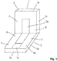
- Fig. 1 shows a view of a seat
- Fig. 2a shows a basic embodiment of the seat with individualized autonomous heating system
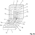
- Fig. 2b shows another variant of embodiment of a similar solution of Fig. 2a , but using the preferred shape of the autonomous heating elements
- Fig. 3 is another alternative embodiment of the seat with an individualized autonomous heating system
- Fig. 4 is an exemplary embodiment of a heating coil switched by the pressure action of a spring-loaded switch.
- Fig. 1 shows a heated seat for means of transport.
- the seat according to Fig. 1 consists of a backrest 1 of the seat and a bottom seat 2 .
- the backrest 1 and the bottom seat 2 of the seat are spatially delimited at their sides by the side surface 3 of the seat, which can be distinguished more specifically into a side surface 3a of the backrest, a side surface 3b of the seat bottom, an upper side surface 3c of the backrest and a front side surface 3d of the seat bottom.
- the seat in the part of the backrest 1 and in the part of the seat bottom 2 is spatially delimited by a support surface 4 which serves as a support surface for a person sitting on the seat.
- the support surface 4 of the seat is divided into two zones, into the central zone 5 of the support surface 4 of the seat and into the edge zones 6 of the support surface 4 of the seat, which are arranged on both sides of the central zone 5 .
- the central zone 5 of the support surface 4 of the seat consists of the central zone 5a of the support surface of the seat backrest 1 and of the central zone 5b of the support surface of the seat bottom 2 of the seat.
- the central zone 5a and the central zone 5b are adjacent.
- both the central zone 5a , and the central zone 5b have the shape of a quadrilateral, in particular a rectangle, but it is clear that this shape can be replaced by a semicircle of approximately the same size or by a semi-oval shape or by another suitable shape.
- the central zone 5b of the support surface of the seat bottom may be adjacent (but not necessarily) to an extension 5c (shown by a dashed line in Fig. 1 ) of the central zone 5b of the seat bottom such that the central zone 5 of the seat support surface touches the front side surface 3d of the seat bottom 2 with this extension 5c .
- the edge zone 6 of the support surface 4 of the seat is located along the entire circumference of the central zone 5 of the seat, between the central zone 5 of the seat and the side surface 3 of the seat.
- the central zone 5 is adjacent to the front side surface 3d of the seat bottom 2 of the seat.
- Fig. 2a shows a first variant of an exemplary embodiment using small autonomous heating elements (8) having a substantially centrally symmetrical flat shape, such as the shape of a circular plate.
- Fig. 2a shows a seat comprising a backrest 1 and a seat bottom 2 .
- the support surface 4 of the seat is divided into a central zone 5 and an edge zone 6 .
- the edge zone 6 is in this embodiment located along the entire circumference of the central zone 5 , that is, between the central zone 5 and the side surface 3 of the seat.
- the central zone 5 in this exemplary embodiment does not comprise the extension 5c ( Fig. 1 ) of the central zone 5b of the support surface of the seat bottom 2 of the seat.
- a heating element 7 which is formed in this exemplary embodiment by a heating resistance wire, but a different heating element can also be used, for example a printed heating plate, heating foil or heating fabric.
- Located in the edge zone 6 of the support surface 4 of the seat is a set of autonomous heating elements 8 which have in this exemplary embodiment a circular shape and are connected in parallel to an unillustrated power source.
- the autonomous heating elements 8 approximately U - shaped, or having the shape of concentric semicircles, are arranged in several rows around the central zone 5 . In the embodiment shown in Fig. 2a , a plurality of autonomous circular heating elements 8 are used, whereby the number of these heating elements 8 may vary with respect to the size of the seat used.
- Each of these autonomous heating elements 8 is equipped with an independent pressure switch.
- the pressure sensor is a part of the autonomous heating element 8 and is not shown in Fig. 2a . It is obvious to a person skilled in the art that several different types of pressure switches can be used, in the exemplary embodiment it is a mechanical pressure switch 10 with a spring 11 shown in Fig. 4 that is used.
- Fig. 2b schematically represents a second variant of the first exemplary embodiment of the invention in which the rows of autonomous heating elements 8 are replaced by one autonomous heating element 8 of elongated shape, for example by a heating resistance wire.
- the autonomous heating elements 8 preferably have a U-shape or the shape of a semicircle arranged around the central zone 5 .
- the first, inner autonomous heating element 8a of the backrest 1 of the seat is in the edge zone 6 located such that it surrounds the heating element 7 of the central zone 5 from three sides which are perpendicular to each other.
- the second, outer autonomous heating element 8b of the backrest 1 of the seat is larger than the first autonomous heating element 8 and is disposed such that from three sides perpendicular to each other it surrounds the first autonomous heating element 8a .
- the first, inner autonomous heating element 8c of the seat bottom 2 of the seat in the edge zone 6 is located such that surrounds the heating element 7 of the central zone 5 from three sides perpendicular to each other.
- the second, outer autonomous heating element 8d of the seat bottom 2 of the seat is larger than the first autonomous heating element 8 and is disposed such that it surrounds the first autonomous heating element 8c from three sides perpendicular to each other.
- Each of the autonomous heating elements 8a, 8b, 8c, 8d is switched by an independent pressure switch 10 .
- the heating element 7 located in the central zone 5 is in both variants of the first exemplary embodiment described above manually switched and serves to heat the seat in the central zone 5, which is designed to correspond to the height and width of a slender seated figure.
- the autonomous heating elements 8 disposed in the edge zone 6 serve to heat the support surface 4 of the seat which corresponds to the area of the contact of the support surface 4 with the body of a medium or heavy figure. If a person who touches with his or her body the edge zone 6 of the support surface of the seat 4 sits in the seat while the heating of the seat by the heating element 7 is switched on, the respective pressure switches 10 are pressed by gravity acting on the body of this person, the respective autonomous heating elements 8 are switched on and the edge zone 6 of the support surface 4 of the seat is heated.
- the first heating element 7 may be supplemented by other unillustrated heating elements located in the central zone 5 of the support surface 4 of the seat, or it may be divided into an independent heating element 7a of the central zone 5a of the support surface of the backrest 1 of the seat and an independent heating element 7b of the central zone 5b of the support surface of the seat bottom 2 of the seat.
- the heating element 7 is manually switched in the exemplary embodiment, however, if necessary, for example in construction machines, where it is assumed that the driver often moves away from the seat without switching off the machine, the heating element 7 can also be supplemented by a pressure switch (not shown) located in the central zone 5b of the support surface of the seat bottom 2 of the seat.
- Fig. 3 shows a seat consisting of a backrest 1 and of a seat bottom 2 and the support surface 4 of the seat is divided into a central zone 5 and an edge zone 6 .
- the central zone 5 of the seat bottom 2 in this exemplary embodiment comprises the extension 5c of the central zone 5b of the support surface of the seat bottom 2 of the seat.
- the edge zone 6 of the seat bottom 2 is in this embodiment arranged along the circumference of the central zone 5 and is located between the central zone 5 and the side surfaces 3a , 3b , 3c .
- a heating element 7 is arranged in the central zone 5 of the seat.
- a plurality of autonomous heating elements 8 are arranged in the edge zone 6 of the support surface 4 of the seat.
- several autonomous heating elements 8 are connected in a row 9 switched by a pressure switch 10 .
- there are four rows 9 of autonomous heating elements 8 each of these rows being switched by one pressure switch 10 .
- a pressure switch 10 with a spring 11 shown in Fig. 4 is used.
- Each of the rows 9 of connected autonomous heating elements 8 consists of several autonomous heating elements 8 of the edge zone 6 , which are connected in series with a conductor 12 .
- the autonomous heating elements 8 are in this case printed square-shaped heating plates, but apparently, the construction of the rows 9 of autonomous heating elements described in this exemplary embodiment is suitable also for other types of heating elements which have a shape of a flat plate.
- Two rows 9 of connected autonomous heating elements 8 are disposed in the edge zone 6 of the support surface 4 of the seat backrest 1 and another four rows 9 of autonomous heating elements 8 are disposed in the edge zone 6 of the support surface 4 of the seat bottom 2 of the seat, whereby the number of the rows 9 of these heating elements 8 may vary with respect to the size of the seat used.
- the rows 9 of connected autonomous heating elements 8 disposed in the seat backrest 1 are arranged such that the first row 9a of autonomous heating elements 8 has an inverted U -shape and surrounds the central zone 5a from three sides.
- the second row 9b of connected autonomous heating elements 8 is larger than the first row 9a and comprises more autonomous heating elements 8 than the row 9a .
- This row 9b also has an inverted U -shape and is disposed in the seat backrest 1 between the first row 9a of autonomous heating elements 8 and the side surface 3 of the seat backrest 1 .
- the rows 9c and 9d of connected autonomous heating elements 8 located in the bottom seat 2 of the seat in the case of the second exemplary embodiment ( Fig. 3 ) are arranged such that along each side of the central zone 5b with the extension 5c of the central zone is located one inner row 9c of autonomous heating elements 8 and one outer row 9d of autonomous heating elements 8 in the edge zone 6 of the support surface of the seat bottom. According to the size of the seat, it is possible to locate other unillustrated rows of autonomous heating elements in a similar manner along each side of the central zone 5b with the extension 5c .
- the heating element 7 located in the central zone 5 is in this second exemplary embodiment shown in Fig. 3 manually switched and serves to heat the seat in the central zone 5 , which is designed such that it corresponds to the height and width of a slender figure.
- the autonomous heating elements 8 disposed in the edge zone 6 serve to heat the support surface 4 of the seat which corresponds to the area of the contact of the support surface 4 with the body of a medium or heavy figure.
- the respective pressure switches 10 are pressed by gravity acting on the body of this person, the respective rows 9 of autonomous heating elements 8 are switched on and the edge zone 6 of the support surface 4 of the seat is heated.
- the first heating element 7 may be supplemented by other unillustrated heating elements located in the central zone 5 of the support surface 4 of the seat, optionally it may be divided into an independent heating element of the central zone 5a of the support surface of the seat backrest 1 and an independent heating element of the central zone 5b of the support surface of the seat bottom 2 of the seat.
- This heating element 7 is in the exemplary embodiment manually switched, however, if necessary, for example in some building machines, where it is assumed that the driver often moves away from the seat without switching off the machine, the heating element 7 can be supplemented by a pressure switch 10 located in the central zone 5b of the support surface of the seat bottom 2 of the seat.
Landscapes
- Engineering & Computer Science (AREA)
- Aviation & Aerospace Engineering (AREA)
- Transportation (AREA)
- Mechanical Engineering (AREA)
- Chair Legs, Seat Parts, And Backrests (AREA)
Applications Claiming Priority (1)
| Application Number | Priority Date | Filing Date | Title |
|---|---|---|---|
| CZ2020-37466U CZ34885U1 (cs) | 2020-04-22 | 2020-04-22 | Vyhřívaná sedačka pro vozidla, dopravní prostředky a zemědělské nebo stavební stroje |
Publications (2)
| Publication Number | Publication Date |
|---|---|
| EP3900579A1 true EP3900579A1 (de) | 2021-10-27 |
| EP3900579B1 EP3900579B1 (de) | 2022-10-12 |
Family
ID=70740410
Family Applications (1)
| Application Number | Title | Priority Date | Filing Date |
|---|---|---|---|
| EP20171505.9A Active EP3900579B1 (de) | 2020-04-22 | 2020-04-27 | Beheizter sitz für fahrzeuge, transportmittel und landwirtschaftliche oder baumaschinen |
Country Status (2)
| Country | Link |
|---|---|
| EP (1) | EP3900579B1 (de) |
| CZ (1) | CZ34885U1 (de) |
Cited By (1)
| Publication number | Priority date | Publication date | Assignee | Title |
|---|---|---|---|---|
| JP2024132526A (ja) * | 2023-03-17 | 2024-10-01 | 日本発條株式会社 | シートヒータ及び車両用シート |
Families Citing this family (1)
| Publication number | Priority date | Publication date | Assignee | Title |
|---|---|---|---|---|
| DE102024127021A1 (de) | 2024-09-19 | 2026-03-19 | Dr. Ing. H.C. F. Porsche Aktiengesellschaft | Verfahren zum Beheizen eines Fahrzeugsitzes sowie entsprechender Fahrzeugsitz |
Citations (6)
| Publication number | Priority date | Publication date | Assignee | Title |
|---|---|---|---|---|
| CS172474B1 (de) | 1972-01-24 | 1977-01-28 | ||
| EP2008865A1 (de) * | 2006-04-18 | 2008-12-31 | Toyota Jidosha Kabushiki Kaisha | Insassenwärmvorrichtung für ein fahrzeug |
| JP2009269480A (ja) * | 2008-05-08 | 2009-11-19 | Panasonic Corp | 座席用ヒータ |
| CZ23763U1 (cs) | 2011-12-30 | 2012-05-10 | Technická univerzita v Liberci | Vyhřívaná automobilová sedačka |
| EP2514633A1 (de) * | 2009-12-14 | 2012-10-24 | Panasonic Corporation | Sitzwärmer |
| JP2015039896A (ja) * | 2013-08-20 | 2015-03-02 | 日産自動車株式会社 | シートヒータ装置 |
-
2020
- 2020-04-22 CZ CZ2020-37466U patent/CZ34885U1/cs active Protection Beyond IP Right Term
- 2020-04-27 EP EP20171505.9A patent/EP3900579B1/de active Active
Patent Citations (6)
| Publication number | Priority date | Publication date | Assignee | Title |
|---|---|---|---|---|
| CS172474B1 (de) | 1972-01-24 | 1977-01-28 | ||
| EP2008865A1 (de) * | 2006-04-18 | 2008-12-31 | Toyota Jidosha Kabushiki Kaisha | Insassenwärmvorrichtung für ein fahrzeug |
| JP2009269480A (ja) * | 2008-05-08 | 2009-11-19 | Panasonic Corp | 座席用ヒータ |
| EP2514633A1 (de) * | 2009-12-14 | 2012-10-24 | Panasonic Corporation | Sitzwärmer |
| CZ23763U1 (cs) | 2011-12-30 | 2012-05-10 | Technická univerzita v Liberci | Vyhřívaná automobilová sedačka |
| JP2015039896A (ja) * | 2013-08-20 | 2015-03-02 | 日産自動車株式会社 | シートヒータ装置 |
Cited By (1)
| Publication number | Priority date | Publication date | Assignee | Title |
|---|---|---|---|---|
| JP2024132526A (ja) * | 2023-03-17 | 2024-10-01 | 日本発條株式会社 | シートヒータ及び車両用シート |
Also Published As
| Publication number | Publication date |
|---|---|
| EP3900579B1 (de) | 2022-10-12 |
| CZ34885U1 (cs) | 2021-03-02 |
Similar Documents
| Publication | Publication Date | Title |
|---|---|---|
| EP3900579A1 (de) | Beheizter sitz für fahrzeuge, transportmittel und landwirtschaftliche oder baumaschinen | |
| RU2662119C2 (ru) | Кресло с мультиконтурной системой для транспортного средства | |
| JP5635119B2 (ja) | 着座センサ、及び、それを用いた座席装置 | |
| CN104494487B (zh) | 具有座椅加热器和乘客感应天线的组合式装置及其制造方法 | |
| EP2532543B1 (de) | Sitzwärmer | |
| US3017493A (en) | Heated car seat | |
| US20090008377A1 (en) | Occupant sensing heat mat | |
| EP3359418B1 (de) | Wärmeleitfähige wattierung | |
| US8926010B2 (en) | Vehicle seat | |
| JP5636375B2 (ja) | 座席用ヒータ | |
| EP3391705B1 (de) | Heiz- und kühlmotor | |
| WO2014058429A1 (en) | Ventilated and heated vehicle seat assembly | |
| US20190371995A1 (en) | Thermoelectric device with parallel elements | |
| DE102013107811A1 (de) | Sitzsystem | |
| JP2016120851A (ja) | 乗物用シート | |
| KR102357519B1 (ko) | 섬유형 체압 센서, 체압 프로파일의 생성 방법 및 수집된 체압 정보의 활용 방법 | |
| US20190375321A1 (en) | Vehicle interior equipment | |
| JP2015047379A (ja) | シートヒータ装置およびその制御方法 | |
| CN211933378U (zh) | 沙发 | |
| JP2009247634A (ja) | 暖房用の座席 | |
| JP5906974B2 (ja) | マトリクス状布 | |
| US20200282883A1 (en) | Seat heating device | |
| JP2018058586A (ja) | 荷重検知装置 | |
| US9409496B2 (en) | Seat configured for occupancy state detection | |
| JP2006302670A (ja) | Ptc面状発熱体およびこれを備えた車両用シート |
Legal Events
| Date | Code | Title | Description |
|---|---|---|---|
| PUAI | Public reference made under article 153(3) epc to a published international application that has entered the european phase |
Free format text: ORIGINAL CODE: 0009012 |
|
| STAA | Information on the status of an ep patent application or granted ep patent |
Free format text: STATUS: THE APPLICATION HAS BEEN PUBLISHED |
|
| AK | Designated contracting states |
Kind code of ref document: A1 Designated state(s): AL AT BE BG CH CY CZ DE DK EE ES FI FR GB GR HR HU IE IS IT LI LT LU LV MC MK MT NL NO PL PT RO RS SE SI SK SM TR |
|
| B565 | Issuance of search results under rule 164(2) epc |
Effective date: 20201119 |
|
| STAA | Information on the status of an ep patent application or granted ep patent |
Free format text: STATUS: REQUEST FOR EXAMINATION WAS MADE |
|
| 17P | Request for examination filed |
Effective date: 20211101 |
|
| RBV | Designated contracting states (corrected) |
Designated state(s): AL AT BE BG CH CY CZ DE DK EE ES FI FR GB GR HR HU IE IS IT LI LT LU LV MC MK MT NL NO PL PT RO RS SE SI SK SM TR |
|
| REG | Reference to a national code |
Ref country code: DE Ref legal event code: R079 Ref document number: 602020005554 Country of ref document: DE Free format text: PREVIOUS MAIN CLASS: A47C0007740000 Ipc: H05B0003260000 |
|
| RIC1 | Information provided on ipc code assigned before grant |
Ipc: B60N 2/56 20060101ALI20220328BHEP Ipc: A47C 7/74 20060101ALI20220328BHEP Ipc: H05B 3/34 20060101ALI20220328BHEP Ipc: H05B 3/26 20060101AFI20220328BHEP |
|
| GRAP | Despatch of communication of intention to grant a patent |
Free format text: ORIGINAL CODE: EPIDOSNIGR1 |
|
| STAA | Information on the status of an ep patent application or granted ep patent |
Free format text: STATUS: GRANT OF PATENT IS INTENDED |
|
| INTG | Intention to grant announced |
Effective date: 20220713 |
|
| GRAS | Grant fee paid |
Free format text: ORIGINAL CODE: EPIDOSNIGR3 |
|
| GRAA | (expected) grant |
Free format text: ORIGINAL CODE: 0009210 |
|
| STAA | Information on the status of an ep patent application or granted ep patent |
Free format text: STATUS: THE PATENT HAS BEEN GRANTED |
|
| AK | Designated contracting states |
Kind code of ref document: B1 Designated state(s): AL AT BE BG CH CY CZ DE DK EE ES FI FR GB GR HR HU IE IS IT LI LT LU LV MC MK MT NL NO PL PT RO RS SE SI SK SM TR |
|
| REG | Reference to a national code |
Ref country code: GB Ref legal event code: FG4D |
|
| REG | Reference to a national code |
Ref country code: CH Ref legal event code: EP |
|
| REG | Reference to a national code |
Ref country code: DE Ref legal event code: R096 Ref document number: 602020005554 Country of ref document: DE |
|
| REG | Reference to a national code |
Ref country code: IE Ref legal event code: FG4D |
|
| REG | Reference to a national code |
Ref country code: AT Ref legal event code: REF Ref document number: 1524950 Country of ref document: AT Kind code of ref document: T Effective date: 20221115 |
|
| REG | Reference to a national code |
Ref country code: LT Ref legal event code: MG9D |
|
| REG | Reference to a national code |
Ref country code: NL Ref legal event code: MP Effective date: 20221012 |
|
| REG | Reference to a national code |
Ref country code: AT Ref legal event code: MK05 Ref document number: 1524950 Country of ref document: AT Kind code of ref document: T Effective date: 20221012 |
|
| PG25 | Lapsed in a contracting state [announced via postgrant information from national office to epo] |
Ref country code: NL Free format text: LAPSE BECAUSE OF FAILURE TO SUBMIT A TRANSLATION OF THE DESCRIPTION OR TO PAY THE FEE WITHIN THE PRESCRIBED TIME-LIMIT Effective date: 20221012 |
|
| PG25 | Lapsed in a contracting state [announced via postgrant information from national office to epo] |
Ref country code: SE Free format text: LAPSE BECAUSE OF FAILURE TO SUBMIT A TRANSLATION OF THE DESCRIPTION OR TO PAY THE FEE WITHIN THE PRESCRIBED TIME-LIMIT Effective date: 20221012 Ref country code: PT Free format text: LAPSE BECAUSE OF FAILURE TO SUBMIT A TRANSLATION OF THE DESCRIPTION OR TO PAY THE FEE WITHIN THE PRESCRIBED TIME-LIMIT Effective date: 20230213 Ref country code: NO Free format text: LAPSE BECAUSE OF FAILURE TO SUBMIT A TRANSLATION OF THE DESCRIPTION OR TO PAY THE FEE WITHIN THE PRESCRIBED TIME-LIMIT Effective date: 20230112 Ref country code: LT Free format text: LAPSE BECAUSE OF FAILURE TO SUBMIT A TRANSLATION OF THE DESCRIPTION OR TO PAY THE FEE WITHIN THE PRESCRIBED TIME-LIMIT Effective date: 20221012 Ref country code: FI Free format text: LAPSE BECAUSE OF FAILURE TO SUBMIT A TRANSLATION OF THE DESCRIPTION OR TO PAY THE FEE WITHIN THE PRESCRIBED TIME-LIMIT Effective date: 20221012 Ref country code: ES Free format text: LAPSE BECAUSE OF FAILURE TO SUBMIT A TRANSLATION OF THE DESCRIPTION OR TO PAY THE FEE WITHIN THE PRESCRIBED TIME-LIMIT Effective date: 20221012 Ref country code: AT Free format text: LAPSE BECAUSE OF FAILURE TO SUBMIT A TRANSLATION OF THE DESCRIPTION OR TO PAY THE FEE WITHIN THE PRESCRIBED TIME-LIMIT Effective date: 20221012 |
|
| PG25 | Lapsed in a contracting state [announced via postgrant information from national office to epo] |
Ref country code: RS Free format text: LAPSE BECAUSE OF FAILURE TO SUBMIT A TRANSLATION OF THE DESCRIPTION OR TO PAY THE FEE WITHIN THE PRESCRIBED TIME-LIMIT Effective date: 20221012 Ref country code: PL Free format text: LAPSE BECAUSE OF FAILURE TO SUBMIT A TRANSLATION OF THE DESCRIPTION OR TO PAY THE FEE WITHIN THE PRESCRIBED TIME-LIMIT Effective date: 20221012 Ref country code: LV Free format text: LAPSE BECAUSE OF FAILURE TO SUBMIT A TRANSLATION OF THE DESCRIPTION OR TO PAY THE FEE WITHIN THE PRESCRIBED TIME-LIMIT Effective date: 20221012 Ref country code: IS Free format text: LAPSE BECAUSE OF FAILURE TO SUBMIT A TRANSLATION OF THE DESCRIPTION OR TO PAY THE FEE WITHIN THE PRESCRIBED TIME-LIMIT Effective date: 20230212 Ref country code: HR Free format text: LAPSE BECAUSE OF FAILURE TO SUBMIT A TRANSLATION OF THE DESCRIPTION OR TO PAY THE FEE WITHIN THE PRESCRIBED TIME-LIMIT Effective date: 20221012 Ref country code: GR Free format text: LAPSE BECAUSE OF FAILURE TO SUBMIT A TRANSLATION OF THE DESCRIPTION OR TO PAY THE FEE WITHIN THE PRESCRIBED TIME-LIMIT Effective date: 20230113 |
|
| REG | Reference to a national code |
Ref country code: DE Ref legal event code: R097 Ref document number: 602020005554 Country of ref document: DE |
|
| P01 | Opt-out of the competence of the unified patent court (upc) registered |
Effective date: 20230609 |
|
| PG25 | Lapsed in a contracting state [announced via postgrant information from national office to epo] |
Ref country code: SM Free format text: LAPSE BECAUSE OF FAILURE TO SUBMIT A TRANSLATION OF THE DESCRIPTION OR TO PAY THE FEE WITHIN THE PRESCRIBED TIME-LIMIT Effective date: 20221012 Ref country code: RO Free format text: LAPSE BECAUSE OF FAILURE TO SUBMIT A TRANSLATION OF THE DESCRIPTION OR TO PAY THE FEE WITHIN THE PRESCRIBED TIME-LIMIT Effective date: 20221012 Ref country code: EE Free format text: LAPSE BECAUSE OF FAILURE TO SUBMIT A TRANSLATION OF THE DESCRIPTION OR TO PAY THE FEE WITHIN THE PRESCRIBED TIME-LIMIT Effective date: 20221012 Ref country code: DK Free format text: LAPSE BECAUSE OF FAILURE TO SUBMIT A TRANSLATION OF THE DESCRIPTION OR TO PAY THE FEE WITHIN THE PRESCRIBED TIME-LIMIT Effective date: 20221012 Ref country code: CZ Free format text: LAPSE BECAUSE OF FAILURE TO SUBMIT A TRANSLATION OF THE DESCRIPTION OR TO PAY THE FEE WITHIN THE PRESCRIBED TIME-LIMIT Effective date: 20221012 |
|
| PLBE | No opposition filed within time limit |
Free format text: ORIGINAL CODE: 0009261 |
|
| STAA | Information on the status of an ep patent application or granted ep patent |
Free format text: STATUS: NO OPPOSITION FILED WITHIN TIME LIMIT |
|
| PG25 | Lapsed in a contracting state [announced via postgrant information from national office to epo] |
Ref country code: SK Free format text: LAPSE BECAUSE OF FAILURE TO SUBMIT A TRANSLATION OF THE DESCRIPTION OR TO PAY THE FEE WITHIN THE PRESCRIBED TIME-LIMIT Effective date: 20221012 Ref country code: AL Free format text: LAPSE BECAUSE OF FAILURE TO SUBMIT A TRANSLATION OF THE DESCRIPTION OR TO PAY THE FEE WITHIN THE PRESCRIBED TIME-LIMIT Effective date: 20221012 |
|
| 26N | No opposition filed |
Effective date: 20230713 |
|
| REG | Reference to a national code |
Ref country code: DE Ref legal event code: R119 Ref document number: 602020005554 Country of ref document: DE |
|
| PG25 | Lapsed in a contracting state [announced via postgrant information from national office to epo] |
Ref country code: SI Free format text: LAPSE BECAUSE OF FAILURE TO SUBMIT A TRANSLATION OF THE DESCRIPTION OR TO PAY THE FEE WITHIN THE PRESCRIBED TIME-LIMIT Effective date: 20221012 |
|
| REG | Reference to a national code |
Ref country code: CH Ref legal event code: PL |
|
| PG25 | Lapsed in a contracting state [announced via postgrant information from national office to epo] |
Ref country code: LU Free format text: LAPSE BECAUSE OF NON-PAYMENT OF DUE FEES Effective date: 20230427 |
|
| REG | Reference to a national code |
Ref country code: BE Ref legal event code: MM Effective date: 20230430 |
|
| PG25 | Lapsed in a contracting state [announced via postgrant information from national office to epo] |
Ref country code: MC Free format text: LAPSE BECAUSE OF FAILURE TO SUBMIT A TRANSLATION OF THE DESCRIPTION OR TO PAY THE FEE WITHIN THE PRESCRIBED TIME-LIMIT Effective date: 20221012 |
|
| PG25 | Lapsed in a contracting state [announced via postgrant information from national office to epo] |
Ref country code: MC Free format text: LAPSE BECAUSE OF FAILURE TO SUBMIT A TRANSLATION OF THE DESCRIPTION OR TO PAY THE FEE WITHIN THE PRESCRIBED TIME-LIMIT Effective date: 20221012 Ref country code: LI Free format text: LAPSE BECAUSE OF NON-PAYMENT OF DUE FEES Effective date: 20230430 Ref country code: DE Free format text: LAPSE BECAUSE OF NON-PAYMENT OF DUE FEES Effective date: 20231103 Ref country code: CH Free format text: LAPSE BECAUSE OF NON-PAYMENT OF DUE FEES Effective date: 20230430 |
|
| REG | Reference to a national code |
Ref country code: IE Ref legal event code: MM4A |
|
| PG25 | Lapsed in a contracting state [announced via postgrant information from national office to epo] |
Ref country code: BE Free format text: LAPSE BECAUSE OF NON-PAYMENT OF DUE FEES Effective date: 20230430 |
|
| PG25 | Lapsed in a contracting state [announced via postgrant information from national office to epo] |
Ref country code: IE Free format text: LAPSE BECAUSE OF NON-PAYMENT OF DUE FEES Effective date: 20230427 |
|
| PG25 | Lapsed in a contracting state [announced via postgrant information from national office to epo] |
Ref country code: IE Free format text: LAPSE BECAUSE OF NON-PAYMENT OF DUE FEES Effective date: 20230427 |
|
| PG25 | Lapsed in a contracting state [announced via postgrant information from national office to epo] |
Ref country code: IT Free format text: LAPSE BECAUSE OF FAILURE TO SUBMIT A TRANSLATION OF THE DESCRIPTION OR TO PAY THE FEE WITHIN THE PRESCRIBED TIME-LIMIT Effective date: 20221012 |
|
| PG25 | Lapsed in a contracting state [announced via postgrant information from national office to epo] |
Ref country code: BG Free format text: LAPSE BECAUSE OF FAILURE TO SUBMIT A TRANSLATION OF THE DESCRIPTION OR TO PAY THE FEE WITHIN THE PRESCRIBED TIME-LIMIT Effective date: 20221012 |
|
| PG25 | Lapsed in a contracting state [announced via postgrant information from national office to epo] |
Ref country code: BG Free format text: LAPSE BECAUSE OF FAILURE TO SUBMIT A TRANSLATION OF THE DESCRIPTION OR TO PAY THE FEE WITHIN THE PRESCRIBED TIME-LIMIT Effective date: 20221012 |
|
| GBPC | Gb: european patent ceased through non-payment of renewal fee |
Effective date: 20240427 |
|
| PG25 | Lapsed in a contracting state [announced via postgrant information from national office to epo] |
Ref country code: GB Free format text: LAPSE BECAUSE OF NON-PAYMENT OF DUE FEES Effective date: 20240427 |
|
| PG25 | Lapsed in a contracting state [announced via postgrant information from national office to epo] |
Ref country code: GB Free format text: LAPSE BECAUSE OF NON-PAYMENT OF DUE FEES Effective date: 20240427 |
|
| PG25 | Lapsed in a contracting state [announced via postgrant information from national office to epo] |
Ref country code: CY Free format text: LAPSE BECAUSE OF FAILURE TO SUBMIT A TRANSLATION OF THE DESCRIPTION OR TO PAY THE FEE WITHIN THE PRESCRIBED TIME-LIMIT; INVALID AB INITIO Effective date: 20200427 |
|
| PG25 | Lapsed in a contracting state [announced via postgrant information from national office to epo] |
Ref country code: HU Free format text: LAPSE BECAUSE OF FAILURE TO SUBMIT A TRANSLATION OF THE DESCRIPTION OR TO PAY THE FEE WITHIN THE PRESCRIBED TIME-LIMIT; INVALID AB INITIO Effective date: 20200427 |
|
| PG25 | Lapsed in a contracting state [announced via postgrant information from national office to epo] |
Ref country code: TR Free format text: LAPSE BECAUSE OF FAILURE TO SUBMIT A TRANSLATION OF THE DESCRIPTION OR TO PAY THE FEE WITHIN THE PRESCRIBED TIME-LIMIT Effective date: 20221012 |
|
| PGFP | Annual fee paid to national office [announced via postgrant information from national office to epo] |
Ref country code: FR Payment date: 20260324 Year of fee payment: 7 |