EP3900643B1 - Procédé et appareil permettant de faire passer une suture au travers d'un tissu - Google Patents
Procédé et appareil permettant de faire passer une suture au travers d'un tissu Download PDFInfo
- Publication number
- EP3900643B1 EP3900643B1 EP21179735.2A EP21179735A EP3900643B1 EP 3900643 B1 EP3900643 B1 EP 3900643B1 EP 21179735 A EP21179735 A EP 21179735A EP 3900643 B1 EP3900643 B1 EP 3900643B1
- Authority
- EP
- European Patent Office
- Prior art keywords
- suture
- arm
- distal end
- suture passer
- hollow tube
- Prior art date
- Legal status (The legal status is an assumption and is not a legal conclusion. Google has not performed a legal analysis and makes no representation as to the accuracy of the status listed.)
- Active
Links
Images








































Classifications
-
- A—HUMAN NECESSITIES
- A61—MEDICAL OR VETERINARY SCIENCE; HYGIENE
- A61B—DIAGNOSIS; SURGERY; IDENTIFICATION
- A61B17/00—Surgical instruments, devices or methods
- A61B17/04—Surgical instruments, devices or methods for suturing wounds; Holders or packages for needles or suture materials
- A61B17/0483—Hand-held instruments for holding sutures
-
- A—HUMAN NECESSITIES
- A61—MEDICAL OR VETERINARY SCIENCE; HYGIENE
- A61B—DIAGNOSIS; SURGERY; IDENTIFICATION
- A61B17/00—Surgical instruments, devices or methods
- A61B17/04—Surgical instruments, devices or methods for suturing wounds; Holders or packages for needles or suture materials
- A61B17/06—Needles ; Sutures; Needle-suture combinations; Holders or packages for needles or suture materials
- A61B17/06066—Needles, e.g. needle tip configurations
- A61B17/06109—Big needles, either gripped by hand or connectable to a handle
-
- A—HUMAN NECESSITIES
- A61—MEDICAL OR VETERINARY SCIENCE; HYGIENE
- A61B—DIAGNOSIS; SURGERY; IDENTIFICATION
- A61B17/00—Surgical instruments, devices or methods
- A61B17/04—Surgical instruments, devices or methods for suturing wounds; Holders or packages for needles or suture materials
- A61B17/0485—Devices or means, e.g. loops, for capturing the suture thread and threading it through an opening of a suturing instrument or needle eyelet
-
- A—HUMAN NECESSITIES
- A61—MEDICAL OR VETERINARY SCIENCE; HYGIENE
- A61B—DIAGNOSIS; SURGERY; IDENTIFICATION
- A61B17/00—Surgical instruments, devices or methods
- A61B17/04—Surgical instruments, devices or methods for suturing wounds; Holders or packages for needles or suture materials
- A61B17/06—Needles ; Sutures; Needle-suture combinations; Holders or packages for needles or suture materials
- A61B17/06004—Means for attaching suture to needle
- A61B2017/06009—Means for attaching suture to needle having additional means for releasably clamping the suture to the needle, e.g. actuating rod slideable within the needle
-
- A—HUMAN NECESSITIES
- A61—MEDICAL OR VETERINARY SCIENCE; HYGIENE
- A61B—DIAGNOSIS; SURGERY; IDENTIFICATION
- A61B17/00—Surgical instruments, devices or methods
- A61B17/04—Surgical instruments, devices or methods for suturing wounds; Holders or packages for needles or suture materials
- A61B17/06—Needles ; Sutures; Needle-suture combinations; Holders or packages for needles or suture materials
- A61B17/06066—Needles, e.g. needle tip configurations
- A61B2017/061—Needles, e.g. needle tip configurations hollow or tubular
-
- A—HUMAN NECESSITIES
- A61—MEDICAL OR VETERINARY SCIENCE; HYGIENE
- A61B—DIAGNOSIS; SURGERY; IDENTIFICATION
- A61B17/00—Surgical instruments, devices or methods
- A61B17/30—Surgical pincettes, i.e. surgical tweezers without pivotal connections
- A61B2017/306—Surgical pincettes, i.e. surgical tweezers without pivotal connections holding by means of suction
Definitions
- This invention relates to a suture passer according to claim 1.
- suture In many situations suture must be passed through tissue. In open surgical procedures, the suture is typically attached to a needle and the needle is then used to draw the suture through the tissue.
- closed surgical procedures e.g., so-called "keyhole" surgeries, where an interior surgical site is accessed through a narrow cannula
- Conventional needles are typically inadequate for these situations.
- suture passers are dedicated suture passing instruments generally comprising a shaft, a tissue-penetrating and suture-carrying working tip set at the distal end of the shaft, and a handle set at the proximal end of the shaft.
- suture passers all tend to suffer from one or more deficiencies, including but not limited to: (i) size; (ii) a need to place the suture adjacent to an edge of the tissue; (iii) difficulty in picking up suture on the far side of the tissue; (iv) complexity of operation; (v) cost of manufacture, etc.
- WO2012034131 discloses a suture passer comprising a hollow tube and a clamping rod having a bifurcated distal end.
- the hollow tube further comprises a window which extends radially into the hollow tube.
- the present invention provides a suture passer according to claim 1. Further aspects of the invention are defined by the dependent claims.
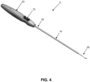
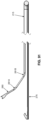
- hollow tube 10 comprises a distal end 20 preferably terminating in a sharp point 22, and a proximal end 25 preferably terminating in a handle 23, with a lumen 30 extending therebetween.
- the pointed hollow tube 10 essentially comprises a hollow needle adapted to pierce tissue.
- Hollow tube 10 further comprises a window 35 which extends radially into the hollow tube and communicates with lumen 30.
- Window 35 is sized so as to selectively receive a suture S therein, as will hereinafter be discussed in further detail.
- Window 35 preferably comprises an inclined distal surface 40 and an inclined proximal surface 45.
- distal surface 40 and proximal surface 45 are inclined in the same direction, and preferably both surfaces are inclined distally (e.g., in the manner shown in Figs. 1-11 ).
- the forward incline of inclined distal surface 40 allows suture to more easily pass into and out of window 35.
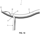
- the forward incline of inclined proximal surface 45 provides an undercut which helps to trap the suture S between the clamping surface 47 of clamping rod 15 and the inclined proximal surface 45 of window 35, as will hereinafter be discussed in further detail.
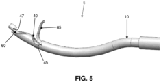
- Clamping rod 15 comprises a distal end 50 ( Fig. 9 ) and a proximal end 55 ( Fig. 9 ). Distal end 50 of clamping rod 15 is bifurcated so as to form a first arm 60 and a second arm 65.
- First arm 60 comprises the aforementioned clamping surface 47, with clamping surface 47 extending radially from the longitudinal axis of clamping rod 15.
- Clamping surface 47 may take the form of a hook, as shown in Figs. 1-11 . This hook helps trap the suture S between clamping surface 47 of clamping rod 15 and inclined proximal surface 45 of window 35, in the manner shown in Figs. 10 and 11 .
- Second arm 65 extends parallel to first arm 60 when clamping rod 15 is disposed within lumen 30 of hollow tube 10, with second arm 65 terminating proximally of first arm 60, shy of clamping surface 47.
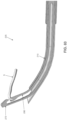
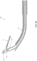
- Second arm 65 is outwardly biased so that when second arm 65 advances past window 35, second arm 65 passes radially outwardly through window 35 so as to project at an angle of approximately 10-120 degrees relative to the adjacent longitudinal axis of first arm 60 ( Fig. 6 ) (i.e., the longitudinal axis of first arm 60 at the point adjacent to where second arm 65 advances outwardly through window 35), and more preferably at an angle of approximately 30-90 degrees to the instantaneous longitudinal axis of first arm 60, whereby to create a funnel region 75 ( Fig. 7 ) between hollow tube 10 and second arm 65 when second arm 65 extends out window 35.
- second arm 65 is preferably formed out of a material consistent with this spring bias (e.g., a superelastic material such as Nitinol, etc.).
- a superelastic material such as Nitinol, etc.
- the entire clamping rod 15 is formed out of a superelastic material such as Nitinol.
- clamping rod 15 extends through lumen 30 of hollow tube 10 and is connected to an actuator 72 ( Fig. 1 ) which is movably mounted to handle 23, such that movement of actuator 72 relative to handle 23 will cause movement of clamping rod 15 relative to hollow tube 10.
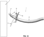
- a piece of suture S may be clamped to the distal end of suture passer 5 by (i) moving clamping rod 15 to the position shown in Figs. 5 and 6 (e.g., by moving actuator 72 distally relative to handle 23) so that clamping surface 47 of first arm 60 is distal to window 35, and so that second arm 65 extends out of window 35; (ii) positioning the suture S in window 35 ( Figs.
- a mattress stitch may be placed in the tissue ( Fig. 25 ).
- the suture passer 5 has the ability to both pass (advance) and retrieve (draw) the suture S through and/or around the tissue in a continuous series of steps. This allows the surgeon to complete the desired suture passing without having to remove the suture passer 5 from the portal through which the suture passer 5 is being used. Significantly, this passing/retrieving process can be accomplished with a single instrument, rather than requiring one instrument for passing and a separate instrument for retrieving. This offers significant advantages in convenience and in reducing surgery time.
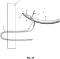
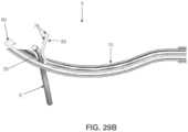
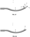
- clamping surface 47 of clamping rod 15 may take the form of a hook, as shown in Figs. 1-11 . This hook may have various degrees of depth and return, as seen in Figs. 26-28 . Alternatively, clamping surface 47 may be substantially flat, as shown in Fig. 29 .
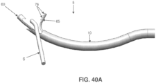
- second arm 65 of suture passer 5 may include a plurality of suture-engaging projections 76 on its distal side.
- Suture-engaging projections 76 allow the user to more aggressively engage (e.g., in a contact or frictional sense) suture S with second arm 65, whereby to facilitate manipulation of suture S via engagement with second arm 65.
- the user can "grip" the suture S with the suture-engaging projections 76 of second arm 65 and "drag" the suture S into a desired position.
- first and second arms 60, 65 of clamping rod 15 can vary from the construction shown in Figs. 1-11 .
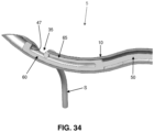
- the distance between the distal tip of second arm 65 and clamping surface 47 is approximately the length of window 35, as shown in Fig. 34 .
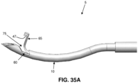
- only a nominal gap is provided between the distal tip of second arm 65 and clamping surface 47 ( Fig. 35 ). This construction can provide for improved capturing of suture S to suture passer 5.
- suction may be applied to lumen 30 of hollow tube 10 proximal to window 35. This suction will draw fluid into window 35, and the fluid entering window 35 will assist suture S in seating itself into window 35 as the suture S approaches window 35.
- the suture passer may further comprise a push rod to assist in ejecting suture S from window 35.
- the push rod may be a component separate from clamping rod 15 (but slidably movable relative thereto), or it may be integrated with clamping rod 15 (e.g., slidably movable thereon).
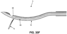
- FIGs. 35A-35C it is also possible to form suture passer 5 so that (i) first arm 60 is shorter than second arm 65, and (ii) clamping surface 47 is formed on the outwardly biased second arm 65 (rather than on first arm 60).
- funnel region 75 is formed between the distal end of shaft 10 and first arm 60.
- Figs. 35D-35F show the suture passer of Figs. 35A-35C securing a suture S to the distal end of the suture passer.
- first arm 60 may be omitted entirely, in which case the distal end of clamping rod 15 preferably comprises only outwardly biased second arm 65.
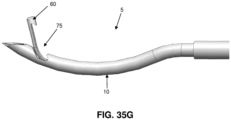
- novel suture passer 5 may be constructed so that first arm 60 (carrying clamping surface 47) is outwardly biased, so that first arm 60 (and clamping surface 47) extends out window 35 when clamping rod 15 is moved distally.
- the funnel region 75 is formed between the distal end of shaft 10 and first arm 60.
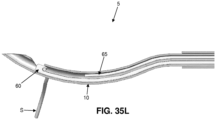
- Figs. 35J-35L show the novel suture passer of Figs. 35G-35I securing a suture S to the distal end of the suture passer.
- first arm 60 is outwardly biased and carries clamping surface 47 (e.g., in the manner shown in Figs. 35G-35I and Figs. 35J-35L )
- second arm 65 may be omitted entirely, in which case the distal end of clamping rod 15 preferably comprises only outwardly biased first arm 60 (with clamping surface 47).
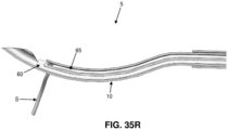
- suture passer 5 may be constructed so that both first arm 60 (carrying clamping surface 47) and second arm 65 are outwardly biased, so that both first arm 60 (and clamping surface 47) and second arm 65 extend out window 35 when clamping rod 15 is moved distally.
- funnel region 75 is formed between first arm 60 and second arm 65.
- Figs. 35P-35R show the suture passer of Figs. 35M-35O securing a suture S to the distal end of the suture passer.
- second arm 65 of suture passer 5 may include a plurality of suture-engaging projections 76 on its distal side.
- suture-engaging projections 76 allow the user to more aggressively engage (e.g., in a contact or frictional sense) suture S with second arm 65, whereby to facilitate manipulation of suture S via engagement with second arm 65.
- the user can "grip" the suture S with the suture-engaging projections 76 of second arm 65 and “drag" the suture S into a desired position.
- suture passer 5 preferably comprises a handle 23, and handle 23 preferably comprises an actuator 72 which actuates clamping rod 15 so as to clamp and/or release suture S.
- actuator 72 may comprise a lock or detent which maintains the position of clamping rod 15 relative to hollow tube 10.
- the lock or detent may hold the clamping rod in a distal position and/or in a proximal position (e.g., while it is clamping suture S).
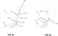
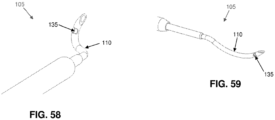
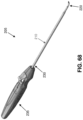
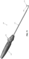
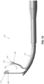
- a suture passer 105 also formed in accordance with the present disclosure.
- Suture passer 105 will sometimes hereinafter be referred to as the "spear" suture passer.
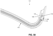
- the function of the inner guide tube 112 can be replaced by a rod 186 with a slot 187, as shown in Fig. 65 .
- This rod 186 could also have other cross-sectional shapes (such as that of a ribbon, etc.) that act to constrain the suture spear 116 to the desired position relative to the window 135.
- This positioning scheme can also take the form of multiple wires filling the space where the suture spear is desired not to go.
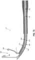
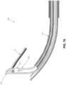
- First arm 275 is outwardly biased so that when first arm 275 advances along cutaway 245, first arm 275 passes radially outwardly through the cutaway so as to project at an angle of approximately 60 degrees relative to the adjacent longitudinal axis of hollow tube 210 (i.e., the longitudinal axis of hollow tube 210 at the point adjacent to where first arm 275 advances through cutaway 245), whereby to create one half of a funnel region 290 established between first arm 275 and second arm 280 when first arm 275 and second arm 280 extend out of cutaway 245 ( Fig. 73 ).
- first arm 275 is preferably formed out of a material consistent with this spring bias (e.g., a superelastic material such as Nitinol, etc.).
- the entire clamping rod 215 is formed out of a superelastic material such as Nitinol.
- first arm 275 and second arm 280 are carefully sized, i.e., it is larger than the diameter of a suture so as to prevent a suture from being inadvertently lodged between first arm 275 and second arm 280, which could effectively jam the components, but not so large that the transfer of suture S from first arm 275 to second arm 280 is undermined.
- the gap between first arm 275 and second arm 280 is approximately 1-3 times the diameter of the suture, and preferably about 1.5 times the diameter of the suture.
- first arm 275 can extend at an angle of 0-90 degrees relative to the adjacent longitudinal axis of hollow tube 210
- second arm 280 can extend at an angle of 20-160 degrees relative to the adjacent longitudinal axis of hollow tube 210 (but in any case at an angle which is greater than the angle of the first arm so that the two arms do not cross over one another). Still other appropriate constructions will be apparent to those skilled in the art in view of the present disclosure.
- the proximal end 270 of clamping rod 215 extends through lumen 240 of hollow tube 210 and is connected to an actuator 320 which is movably mounted to handle 235, such that movement of actuator 320 relative to handle 235 causes movement of clamping rod 215 relative to hollow tube 210.
- a piece of suture S may be clamped to the distal end of suture passer 205 by (i) moving clamping rod 215 to the position shown in Figs. 72 and 73 (e.g., by moving actuator 320 distally relative to handle 235) so that first arm 275 and second arm 285 extend distally and laterally out of cutaway 245 and create the aforementioned funnel region 290; (ii) positioning the suture S in funnel region 290 ( Fig.
- a clamped piece of suture S may thereafter be released from suture passer 205 by (a) moving clamping rod 215 distally ( Figs. 77-81 ) so as to space clamping surface 285 of first arm 275 away from recesses 260 of circumferentially-extending edge 255 of hollow tube 210, whereby to release suture S from its clamped condition, and with recess 295 of second arm 280 engaging suture S and driving it distally and laterally, so that suture S moves clear of cutaway 245 ( Figs.
- suture S to be withdrawn from the suture passer, either by moving suture S relative to suture passer 205, or by moving suture passer 205 relative to suture S, or by moving both suture S and suture passer 205 relative to one another.
- both first arm 275 and second arm 280 are disposed within lumen 230 of hollow tube 210, so that the distal end of suture passer 205 presents a smooth outer surface, whereby to facilitate passage of the distal end of suture passer 205 through tissue.
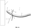
- the novel suture passer 205 can be used to pass suture S from the near side of tissue to the far side of tissue (i.e., in an "antegrade” manner).
- Suture S is then guided into cutaway 245 using this funnel effect, either by moving suture S relative to suture passer 205, or by moving suture passer 205 relative to suture S, or by moving both suture S and suture passer 205 relative to one another.
- the suture S may be tensioned so as to help draw it into cutaway 245.
- suture S may be hooked with clamping surface 285 of first arm 275.
- Clamping rod 215 is then retracted proximally so that clamping surface 285 of first arm 275 clamps suture S between clamping surface 285 of first arm 275 and recesses 260 of circumferentially-extending edge 255 of hollow tube 210.
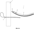
- Suture passer 205 is then advanced distally so that cutaway 245 passes through tissue, whereby to carry suture S through the tissue.
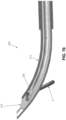
- clamping rod 215 is advanced distally so that first arm 275 and second arm 280 extend out of cutaway 245, thereby spacing clamping surface 285 from circumferentially-extending edge 255 of hollow tube 210, whereby to release suture S from suture passer 205 and with second arm 280 driving suture S before it as second arm 280 advances distally and proximally out of cutaway 245. See Fig. 79 .
- second arm 280 can flex proximally slightly at the end of the distal stroke, whereby to allow suture S to "slip off" the distal end of second arm 280. (see Fig. 81 ).
- second arm 280 is flexible, but also has column strength, so that second arm 280 can drive the suture S distally relative to hollow tube 210, but then, as the portion of second arm 280 projecting out of hollow tube 210 gets longer and longer, the second arm 280 eventually "flops over” under the drag of the suture S which is being pushed by second arm 280, whereby to cause suture S to fall free of second arm 280.
- Suture passer 205 and/or suture S are then manipulated so that suture S is clear of suture passer 205.
- Clamping rod 215 is then moved proximally so as to retract first arm 275 and second arm 280 back into hollow tube 210.
- Suture passer 205 may then be withdrawn back through the tissue, leaving suture S extending through the tissue.
- second arm 280 of clamping rod 215 with a recess 295, the suture being driven forward by second arm 280 of clamping rod 215 can be "controlled" longer during the distal stroke, i.e., the suture can be retained for a longer period of time on the distally-moving second arm 280 of clamping rod 215. As a result, it is possible to advance longer lengths of suture through the tissue without driving the needle further through the tissue.
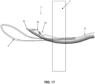
- the novel suture passer 205 can be used to draw suture S from the far side of tissue to the near side of tissue (i.e., in a "retrograde” manner). More particularly, in this form of the disclosure, the suture S is loaded into suture passer 205 on the far side of the tissue. This is done by first passing suture passer 205 through the tissue so that cutaway 245 resides on the far side of the tissue, and then moving clamping rod 215 distally so that first arm 275 and second arm 280 extend distally and proximally out of cutaway 245, whereby to create the aforementioned funnel region 290.
- clamping rod 215 is retracted proximally so as to releasably secure suture S between clamping surface 285 of first arm 275 and recesses 260 of circumferentially-extending edge 255 of hollow tube 210.
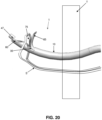
- Suture passer 205 is then retracted proximally through the tissue, carrying suture S therethrough.
- Suture S can then be released from suture passer 205 by moving clamping rod 215 distally, whereby to cause second arm 280 to drive suture S out of cutaway 245 and clear of suture passer 205.
- second arm 280 may be formed without the aforementioned compound curve 315.
- second arm 280 can be formed with proximal finger 305 omitted, so that second arm 280 comprises only the distal finger 300.
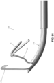
- first arm 275 and second arm 280 both extend at smaller angles (than those previously disclosed) relative to the adjacent longitudinal axis of hollow tube 210. More particularly, in this form of the invention, first arm 275 extends substantially parallel to the adjacent longitudinal axis of hollow tube 210, and second arm 280 extends at an angle of approximately 35 degrees relative to the adjacent longitudinal axis of hollow tube 210. It has been found that by configuring second arm 280 so that it extends at a smaller angle (than those previously disclosed) relative to the adjacent longitudinal axis of hollow tube 210, the suture is more easily released from the tool after the tool has been used to pass suture in an antegrade fashion through the tissue.
- Figs. 87-88 show first arm 275 and second arm 280 in a partially-extended position (i.e., in a position where suture can be adequately retrieved), while Figs. 89-90 show first arm 275 and second arm 280 in a fully-extended position (i.e., in a position where suture can be fully advanced when being passed through tissue).
- Fig. 91 shows clamping rod 215 prior to assembly into suture passer 205.
Landscapes
- Health & Medical Sciences (AREA)
- Life Sciences & Earth Sciences (AREA)
- Surgery (AREA)
- Heart & Thoracic Surgery (AREA)
- Engineering & Computer Science (AREA)
- Biomedical Technology (AREA)
- Nuclear Medicine, Radiotherapy & Molecular Imaging (AREA)
- Medical Informatics (AREA)
- Molecular Biology (AREA)
- Animal Behavior & Ethology (AREA)
- General Health & Medical Sciences (AREA)
- Public Health (AREA)
- Veterinary Medicine (AREA)
- Surgical Instruments (AREA)
Claims (15)
- Passe-fil de suture (5, 205) comprenant :un tube creux (10, 210), le tube creux (10, 210) comprenant une extrémité distale (20, 220), une extrémité proximale (25, 230) et une lumière (30, 240) s'étendant à partir de l'extrémité distale (20, 220) vers l'extrémité proximale (25, 230) ; etune tige de serrage (15, 215) disposée de manière coulissante dans la lumière (30, 240) du tube creux (10, 210), la tige de serrage (15, 215) comprenant une extrémité distale (50, 265) et une extrémité proximale (55, 270), l'extrémité distale (50, 265) étant bifurquée en un premier bras (60, 275) et un deuxième bras (65, 280), le premier bras (60, 275) comportant une surface de serrage (47, 285), et le deuxième bras (65, 280) étant sollicité vers l'extérieur de telle sorte que lorsque la tige de serrage (15, 215) est déplacée de manière distale, l'extrémité distale du deuxième bras (65, 280) s'étend latéralement par rapport au tube creux (10, 210) ;dans lequel l'extrémité distale (20, 220) du tube creux (10, 210) termine en une pointe acérée (225), et le tube creux (10, 210) comprend une découpe (245) formée au niveau de l'extrémité distale (20, 220) du tube creux (10, 210) et s'étendant directement à partir de la pointe acérée (225), la découpe (245) communiquant avec la lumière (30, 240), dans lequel la découpe (245) est formée par une paire de bords s'étendant longitudinalement (250) présentant des extrémités distales et des extrémité proximales, dans lequel la paire de bords s'étendant longitudinalement (250) terminent au niveau d'un bord s'étendant de manière circonférentielle (255) au niveau des extrémités proximales des bords s'étendant longitudinalement (250), dans lequel le bord s'étendant de manière circonférentielle forme des sièges pour un fil de suture saisi par le passe-fil de suture.
- Passe-fil de suture (5, 205) selon la revendication 1, dans lequel la surface de serrage (47, 285) du premier bras (60, 275) est configurée pour retenir de manière libérable un fil de suture (S) à l'extrémité distale du premier bras (60, 275).
- Passe-fil de suture (5, 205) selon la revendication 1 ou revendication 2, dans lequel la surface de serrage (47, 285) comprend un évidement pour placer un fil de suture (S) dans celui-ci de manière libérable.
- Passe-fil de suture (5, 205) selon la revendication 3, dans lequel l'évidement (285) est formé comme un crochet.
- Passe-fil de suture selon l'une quelconque des revendications 1-4, dans lequel le premier bras et le deuxième bras sont tous les deux sollicités vers l'extérieur.
- Passe-fil de suture (5, 205) selon la revendication 5, dans lequel les premier bras (275) et deuxième bras (280) présentent différents degrés de sollicitation latérale de sorte qu'ils définiront conjointement une zone en entonnoir entre ceux-ci lorsque les extrémités distales des premier bras (275) et deuxième bras (280) sont avancées de manière distale en dehors de l'extrémité distale du tube creux (210).
- Passe-fil de suture (5, 205) selon l'une quelconque des revendications 1-4, dans lequel le premier bras ne présente pas de sollicitation vers l'extérieur.
- Passe-fil de suture selon l'une quelconque des revendications 1-7, dans lequel l'extrémité distale du premier bras est distale de l'extrémité distale du deuxième bras.
- Passe-fil de suture selon l'une quelconque des revendications 1-8, dans lequel un interstice (G) est prévu entre l'extrémité distale du deuxième bras et la surface de serrage.
- Passe-fil de suture (5, 205) selon la revendication 9, dans lequel l'interstice (G) est 1-3 fois le diamètre du fil de suture (S).
- Passe-fil de suture (5, 205) selon l'une quelconque des revendications 1-10, dans lequel le bord s'étendant de manière circonférentielle (255) comprend une paire d'évidements s'étendant longitudinalement (260) diamétralement opposés, dimensionnés pour recevoir un fil de suture (S) dans ceux-ci.
- Passe-fil de suture (5, 205) selon l'une quelconque des revendications 1-11, dans lequel, lorsque la tige de serrage (15, 215) est tirée de manière proximale, un fil de suture (S) en prise avec la surface de serrage (47, 285) est tiré de manière proximale contre le bord s'étendant de manière circonférentielle (255) de la découpe (245).
- Passe-fil de suture (5, 205) selon la revendication 12, dans lequel, lorsque le fil de suture (S) en prise avec la surface de serrage (47, 285) est tiré de manière proximale contre le bord s'étendant de manière circonférentielle (255) de la découpe (245), une extrémité distale du premier bras est proximale d'un bout distal du tube creux.
- Passe-fil de suture (5, 205) selon l'une quelconque des revendications 1-13, dans lequel une extrémité distale du premier bras est inclinée.
- Passe-fil de suture (5, 205) selon l'une quelconque des revendications 1-14, dans lequel l'extrémité distale du tube creux (210) est courbée.
Applications Claiming Priority (4)
| Application Number | Priority Date | Filing Date | Title |
|---|---|---|---|
| US201261701920P | 2012-09-17 | 2012-09-17 | |
| US13/791,395 US10098631B2 (en) | 2010-09-10 | 2013-03-08 | Method and apparatus for passing suture through tissue |
| EP13837709.8A EP2897531A4 (fr) | 2012-09-17 | 2013-09-17 | Procédé et appareil pour le passage de suture à travers le tissu |
| PCT/US2013/060167 WO2014043703A1 (fr) | 2012-09-17 | 2013-09-17 | Procédé et appareil pour le passage de suture à travers le tissu |
Related Parent Applications (1)
| Application Number | Title | Priority Date | Filing Date |
|---|---|---|---|
| EP13837709.8A Division EP2897531A4 (fr) | 2012-09-17 | 2013-09-17 | Procédé et appareil pour le passage de suture à travers le tissu |
Publications (3)
| Publication Number | Publication Date |
|---|---|
| EP3900643A2 EP3900643A2 (fr) | 2021-10-27 |
| EP3900643A3 EP3900643A3 (fr) | 2021-12-01 |
| EP3900643B1 true EP3900643B1 (fr) | 2024-07-10 |
Family
ID=50278768
Family Applications (2)
| Application Number | Title | Priority Date | Filing Date |
|---|---|---|---|
| EP13837709.8A Withdrawn EP2897531A4 (fr) | 2012-09-17 | 2013-09-17 | Procédé et appareil pour le passage de suture à travers le tissu |
| EP21179735.2A Active EP3900643B1 (fr) | 2012-09-17 | 2013-09-17 | Procédé et appareil permettant de faire passer une suture au travers d'un tissu |
Family Applications Before (1)
| Application Number | Title | Priority Date | Filing Date |
|---|---|---|---|
| EP13837709.8A Withdrawn EP2897531A4 (fr) | 2012-09-17 | 2013-09-17 | Procédé et appareil pour le passage de suture à travers le tissu |
Country Status (2)
| Country | Link |
|---|---|
| EP (2) | EP2897531A4 (fr) |
| WO (1) | WO2014043703A1 (fr) |
Families Citing this family (6)
| Publication number | Priority date | Publication date | Assignee | Title |
|---|---|---|---|---|
| US7887551B2 (en) | 1999-12-02 | 2011-02-15 | Smith & Nephew, Inc. | Soft tissue attachment and repair |
| US10085735B2 (en) | 2014-10-29 | 2018-10-02 | Smith & Nephew, Inc. | Modular tissue repair kit and devices and method related thereto |
| EP3253300B1 (fr) | 2015-02-04 | 2021-12-15 | Smith & Nephew, Inc. | Aiguille articulée |
| WO2016168422A1 (fr) * | 2015-04-15 | 2016-10-20 | Smith & Nephew, Inc. | Dispositif de préhension de suture et son procédé d'utilisation |
| EP3531931A1 (fr) * | 2016-10-31 | 2019-09-04 | Smith & Nephew, Inc | Instrument de passage et de retenue de fil de suture et procédé associé |
| CN111823597B (zh) * | 2020-06-28 | 2022-08-02 | 宁夏隆基宁光仪表股份有限公司 | 一种机械自动化组装用边框定位夹紧一体化装置 |
Family Cites Families (6)
| Publication number | Priority date | Publication date | Assignee | Title |
|---|---|---|---|---|
| US5181919A (en) * | 1991-04-23 | 1993-01-26 | Arieh Bergman | Suture ligating device for use with an endoscope |
| US5993466A (en) * | 1997-06-17 | 1999-11-30 | Yoon; Inbae | Suturing instrument with multiple rotatably mounted spreadable needle holders |
| US6716224B2 (en) * | 2000-08-28 | 2004-04-06 | Linvatec Corporation | Intracorporeal knot tier |
| WO2011008607A1 (fr) * | 2009-07-15 | 2011-01-20 | Pivot Medical, Inc. | Méthode et appareil de traitement de l'articulation de la hanche, notamment au moyen d'un nouvel instrument de passage de suture, et instrument associé |
| US10123794B2 (en) * | 2010-09-10 | 2018-11-13 | Pivot Medical, Inc. | Method and apparatus for passing suture through tissue |
| US8568428B2 (en) * | 2011-01-05 | 2013-10-29 | Coloplast A/S | Suture system and assembly including a tubular leader having a clasp |
-
2013
- 2013-09-17 EP EP13837709.8A patent/EP2897531A4/fr not_active Withdrawn
- 2013-09-17 WO PCT/US2013/060167 patent/WO2014043703A1/fr not_active Ceased
- 2013-09-17 EP EP21179735.2A patent/EP3900643B1/fr active Active
Also Published As
| Publication number | Publication date |
|---|---|
| EP3900643A3 (fr) | 2021-12-01 |
| EP2897531A1 (fr) | 2015-07-29 |
| EP2897531A4 (fr) | 2016-12-28 |
| EP3900643A2 (fr) | 2021-10-27 |
| WO2014043703A1 (fr) | 2014-03-20 |
Similar Documents
| Publication | Publication Date | Title |
|---|---|---|
| US20220183675A1 (en) | Method and apparatus for passing suture through tissue | |
| US9931114B2 (en) | Method and apparatus for passing suture through tissue | |
| US12622690B2 (en) | Method and apparatus for passing suture through tissue | |
| JP6205492B2 (ja) | 縫合糸パサーおよびその動作方法 | |
| EP3900643A2 (fr) | Procédé et appareil permettant de faire passer une suture au travers d'un tissu | |
| US20100298847A1 (en) | Hydrodynamic suture passer | |
| TW201235002A (en) | Method and apparatus for guiding a suture thread | |
| AU2014348417A1 (en) | Surgical instrument for manipulating and passing suture |
Legal Events
| Date | Code | Title | Description |
|---|---|---|---|
| PUAI | Public reference made under article 153(3) epc to a published international application that has entered the european phase |
Free format text: ORIGINAL CODE: 0009012 |
|
| STAA | Information on the status of an ep patent application or granted ep patent |
Free format text: STATUS: REQUEST FOR EXAMINATION WAS MADE |
|
| 17P | Request for examination filed |
Effective date: 20210616 |
|
| AC | Divisional application: reference to earlier application |
Ref document number: 2897531 Country of ref document: EP Kind code of ref document: P |
|
| AK | Designated contracting states |
Kind code of ref document: A2 Designated state(s): AL AT BE BG CH CY CZ DE DK EE ES FI FR GB GR HR HU IE IS IT LI LT LU LV MC MK MT NL NO PL PT RO RS SE SI SK SM TR |
|
| PUAL | Search report despatched |
Free format text: ORIGINAL CODE: 0009013 |
|
| AK | Designated contracting states |
Kind code of ref document: A3 Designated state(s): AL AT BE BG CH CY CZ DE DK EE ES FI FR GB GR HR HU IE IS IT LI LT LU LV MC MK MT NL NO PL PT RO RS SE SI SK SM TR |
|
| RIC1 | Information provided on ipc code assigned before grant |
Ipc: A61B 17/062 20060101AFI20211022BHEP |
|
| STAA | Information on the status of an ep patent application or granted ep patent |
Free format text: STATUS: EXAMINATION IS IN PROGRESS |
|
| 17Q | First examination report despatched |
Effective date: 20221019 |
|
| GRAP | Despatch of communication of intention to grant a patent |
Free format text: ORIGINAL CODE: EPIDOSNIGR1 |
|
| STAA | Information on the status of an ep patent application or granted ep patent |
Free format text: STATUS: GRANT OF PATENT IS INTENDED |
|
| INTG | Intention to grant announced |
Effective date: 20240205 |
|
| P01 | Opt-out of the competence of the unified patent court (upc) registered |
Effective date: 20240215 |
|
| GRAS | Grant fee paid |
Free format text: ORIGINAL CODE: EPIDOSNIGR3 |
|
| GRAA | (expected) grant |
Free format text: ORIGINAL CODE: 0009210 |
|
| STAA | Information on the status of an ep patent application or granted ep patent |
Free format text: STATUS: THE PATENT HAS BEEN GRANTED |
|
| AC | Divisional application: reference to earlier application |
Ref document number: 2897531 Country of ref document: EP Kind code of ref document: P |
|
| AK | Designated contracting states |
Kind code of ref document: B1 Designated state(s): AL AT BE BG CH CY CZ DE DK EE ES FI FR GB GR HR HU IE IS IT LI LT LU LV MC MK MT NL NO PL PT RO RS SE SI SK SM TR |
|
| REG | Reference to a national code |
Ref country code: CH Ref legal event code: EP |
|
| REG | Reference to a national code |
Ref country code: DE Ref legal event code: R096 Ref document number: 602013085900 Country of ref document: DE |
|
| REG | Reference to a national code |
Ref country code: NL Ref legal event code: FP |
|
| REG | Reference to a national code |
Ref country code: LT Ref legal event code: MG9D |
|
| PG25 | Lapsed in a contracting state [announced via postgrant information from national office to epo] |
Ref country code: PT Free format text: LAPSE BECAUSE OF FAILURE TO SUBMIT A TRANSLATION OF THE DESCRIPTION OR TO PAY THE FEE WITHIN THE PRESCRIBED TIME-LIMIT Effective date: 20241111 |
|
| REG | Reference to a national code |
Ref country code: AT Ref legal event code: MK05 Ref document number: 1701310 Country of ref document: AT Kind code of ref document: T Effective date: 20240710 |
|
| RAP4 | Party data changed (patent owner data changed or rights of a patent transferred) |
Owner name: STRYKER CORPORATION |
|
| PG25 | Lapsed in a contracting state [announced via postgrant information from national office to epo] |
Ref country code: PT Free format text: LAPSE BECAUSE OF FAILURE TO SUBMIT A TRANSLATION OF THE DESCRIPTION OR TO PAY THE FEE WITHIN THE PRESCRIBED TIME-LIMIT Effective date: 20241111 |
|
| PG25 | Lapsed in a contracting state [announced via postgrant information from national office to epo] |
Ref country code: NO Free format text: LAPSE BECAUSE OF FAILURE TO SUBMIT A TRANSLATION OF THE DESCRIPTION OR TO PAY THE FEE WITHIN THE PRESCRIBED TIME-LIMIT Effective date: 20241010 |
|
| PG25 | Lapsed in a contracting state [announced via postgrant information from national office to epo] |
Ref country code: FI Free format text: LAPSE BECAUSE OF FAILURE TO SUBMIT A TRANSLATION OF THE DESCRIPTION OR TO PAY THE FEE WITHIN THE PRESCRIBED TIME-LIMIT Effective date: 20240710 Ref country code: PL Free format text: LAPSE BECAUSE OF FAILURE TO SUBMIT A TRANSLATION OF THE DESCRIPTION OR TO PAY THE FEE WITHIN THE PRESCRIBED TIME-LIMIT Effective date: 20240710 Ref country code: GR Free format text: LAPSE BECAUSE OF FAILURE TO SUBMIT A TRANSLATION OF THE DESCRIPTION OR TO PAY THE FEE WITHIN THE PRESCRIBED TIME-LIMIT Effective date: 20241011 |
|
| PG25 | Lapsed in a contracting state [announced via postgrant information from national office to epo] |
Ref country code: BG Free format text: LAPSE BECAUSE OF FAILURE TO SUBMIT A TRANSLATION OF THE DESCRIPTION OR TO PAY THE FEE WITHIN THE PRESCRIBED TIME-LIMIT Effective date: 20240710 |
|
| PG25 | Lapsed in a contracting state [announced via postgrant information from national office to epo] |
Ref country code: LV Free format text: LAPSE BECAUSE OF FAILURE TO SUBMIT A TRANSLATION OF THE DESCRIPTION OR TO PAY THE FEE WITHIN THE PRESCRIBED TIME-LIMIT Effective date: 20240710 |
|
| PG25 | Lapsed in a contracting state [announced via postgrant information from national office to epo] |
Ref country code: IS Free format text: LAPSE BECAUSE OF FAILURE TO SUBMIT A TRANSLATION OF THE DESCRIPTION OR TO PAY THE FEE WITHIN THE PRESCRIBED TIME-LIMIT Effective date: 20241110 Ref country code: AT Free format text: LAPSE BECAUSE OF FAILURE TO SUBMIT A TRANSLATION OF THE DESCRIPTION OR TO PAY THE FEE WITHIN THE PRESCRIBED TIME-LIMIT Effective date: 20240710 |
|
| PG25 | Lapsed in a contracting state [announced via postgrant information from national office to epo] |
Ref country code: HR Free format text: LAPSE BECAUSE OF FAILURE TO SUBMIT A TRANSLATION OF THE DESCRIPTION OR TO PAY THE FEE WITHIN THE PRESCRIBED TIME-LIMIT Effective date: 20240710 |
|
| PG25 | Lapsed in a contracting state [announced via postgrant information from national office to epo] |
Ref country code: RS Free format text: LAPSE BECAUSE OF FAILURE TO SUBMIT A TRANSLATION OF THE DESCRIPTION OR TO PAY THE FEE WITHIN THE PRESCRIBED TIME-LIMIT Effective date: 20241010 Ref country code: ES Free format text: LAPSE BECAUSE OF FAILURE TO SUBMIT A TRANSLATION OF THE DESCRIPTION OR TO PAY THE FEE WITHIN THE PRESCRIBED TIME-LIMIT Effective date: 20240710 |
|
| PG25 | Lapsed in a contracting state [announced via postgrant information from national office to epo] |
Ref country code: RS Free format text: LAPSE BECAUSE OF FAILURE TO SUBMIT A TRANSLATION OF THE DESCRIPTION OR TO PAY THE FEE WITHIN THE PRESCRIBED TIME-LIMIT Effective date: 20241010 Ref country code: PL Free format text: LAPSE BECAUSE OF FAILURE TO SUBMIT A TRANSLATION OF THE DESCRIPTION OR TO PAY THE FEE WITHIN THE PRESCRIBED TIME-LIMIT Effective date: 20240710 Ref country code: NO Free format text: LAPSE BECAUSE OF FAILURE TO SUBMIT A TRANSLATION OF THE DESCRIPTION OR TO PAY THE FEE WITHIN THE PRESCRIBED TIME-LIMIT Effective date: 20241010 Ref country code: LV Free format text: LAPSE BECAUSE OF FAILURE TO SUBMIT A TRANSLATION OF THE DESCRIPTION OR TO PAY THE FEE WITHIN THE PRESCRIBED TIME-LIMIT Effective date: 20240710 Ref country code: IS Free format text: LAPSE BECAUSE OF FAILURE TO SUBMIT A TRANSLATION OF THE DESCRIPTION OR TO PAY THE FEE WITHIN THE PRESCRIBED TIME-LIMIT Effective date: 20241110 Ref country code: HR Free format text: LAPSE BECAUSE OF FAILURE TO SUBMIT A TRANSLATION OF THE DESCRIPTION OR TO PAY THE FEE WITHIN THE PRESCRIBED TIME-LIMIT Effective date: 20240710 Ref country code: GR Free format text: LAPSE BECAUSE OF FAILURE TO SUBMIT A TRANSLATION OF THE DESCRIPTION OR TO PAY THE FEE WITHIN THE PRESCRIBED TIME-LIMIT Effective date: 20241011 Ref country code: FI Free format text: LAPSE BECAUSE OF FAILURE TO SUBMIT A TRANSLATION OF THE DESCRIPTION OR TO PAY THE FEE WITHIN THE PRESCRIBED TIME-LIMIT Effective date: 20240710 Ref country code: ES Free format text: LAPSE BECAUSE OF FAILURE TO SUBMIT A TRANSLATION OF THE DESCRIPTION OR TO PAY THE FEE WITHIN THE PRESCRIBED TIME-LIMIT Effective date: 20240710 Ref country code: BG Free format text: LAPSE BECAUSE OF FAILURE TO SUBMIT A TRANSLATION OF THE DESCRIPTION OR TO PAY THE FEE WITHIN THE PRESCRIBED TIME-LIMIT Effective date: 20240710 Ref country code: AT Free format text: LAPSE BECAUSE OF FAILURE TO SUBMIT A TRANSLATION OF THE DESCRIPTION OR TO PAY THE FEE WITHIN THE PRESCRIBED TIME-LIMIT Effective date: 20240710 |
|
| REG | Reference to a national code |
Ref country code: DE Ref legal event code: R097 Ref document number: 602013085900 Country of ref document: DE |
|
| PG25 | Lapsed in a contracting state [announced via postgrant information from national office to epo] |
Ref country code: RO Free format text: LAPSE BECAUSE OF FAILURE TO SUBMIT A TRANSLATION OF THE DESCRIPTION OR TO PAY THE FEE WITHIN THE PRESCRIBED TIME-LIMIT Effective date: 20240710 Ref country code: DK Free format text: LAPSE BECAUSE OF FAILURE TO SUBMIT A TRANSLATION OF THE DESCRIPTION OR TO PAY THE FEE WITHIN THE PRESCRIBED TIME-LIMIT Effective date: 20240710 Ref country code: SM Free format text: LAPSE BECAUSE OF FAILURE TO SUBMIT A TRANSLATION OF THE DESCRIPTION OR TO PAY THE FEE WITHIN THE PRESCRIBED TIME-LIMIT Effective date: 20240710 |
|
| PG25 | Lapsed in a contracting state [announced via postgrant information from national office to epo] |
Ref country code: EE Free format text: LAPSE BECAUSE OF FAILURE TO SUBMIT A TRANSLATION OF THE DESCRIPTION OR TO PAY THE FEE WITHIN THE PRESCRIBED TIME-LIMIT Effective date: 20240710 Ref country code: MC Free format text: LAPSE BECAUSE OF FAILURE TO SUBMIT A TRANSLATION OF THE DESCRIPTION OR TO PAY THE FEE WITHIN THE PRESCRIBED TIME-LIMIT Effective date: 20240710 |
|
| PG25 | Lapsed in a contracting state [announced via postgrant information from national office to epo] |
Ref country code: CZ Free format text: LAPSE BECAUSE OF FAILURE TO SUBMIT A TRANSLATION OF THE DESCRIPTION OR TO PAY THE FEE WITHIN THE PRESCRIBED TIME-LIMIT Effective date: 20240710 |
|
| PG25 | Lapsed in a contracting state [announced via postgrant information from national office to epo] |
Ref country code: SK Free format text: LAPSE BECAUSE OF FAILURE TO SUBMIT A TRANSLATION OF THE DESCRIPTION OR TO PAY THE FEE WITHIN THE PRESCRIBED TIME-LIMIT Effective date: 20240710 Ref country code: IT Free format text: LAPSE BECAUSE OF FAILURE TO SUBMIT A TRANSLATION OF THE DESCRIPTION OR TO PAY THE FEE WITHIN THE PRESCRIBED TIME-LIMIT Effective date: 20240710 |
|
| REG | Reference to a national code |
Ref country code: CH Ref legal event code: PL |
|
| PLBE | No opposition filed within time limit |
Free format text: ORIGINAL CODE: 0009261 |
|
| STAA | Information on the status of an ep patent application or granted ep patent |
Free format text: STATUS: NO OPPOSITION FILED WITHIN TIME LIMIT |
|
| PG25 | Lapsed in a contracting state [announced via postgrant information from national office to epo] |
Ref country code: LU Free format text: LAPSE BECAUSE OF NON-PAYMENT OF DUE FEES Effective date: 20240917 |
|
| 26N | No opposition filed |
Effective date: 20250411 |
|
| REG | Reference to a national code |
Ref country code: BE Ref legal event code: MM Effective date: 20240930 |
|
| PG25 | Lapsed in a contracting state [announced via postgrant information from national office to epo] |
Ref country code: BE Free format text: LAPSE BECAUSE OF NON-PAYMENT OF DUE FEES Effective date: 20240930 |
|
| PG25 | Lapsed in a contracting state [announced via postgrant information from national office to epo] |
Ref country code: CH Free format text: LAPSE BECAUSE OF NON-PAYMENT OF DUE FEES Effective date: 20240930 |
|
| PG25 | Lapsed in a contracting state [announced via postgrant information from national office to epo] |
Ref country code: IE Free format text: LAPSE BECAUSE OF NON-PAYMENT OF DUE FEES Effective date: 20240917 |
|
| PGFP | Annual fee paid to national office [announced via postgrant information from national office to epo] |
Ref country code: NL Payment date: 20250704 Year of fee payment: 13 |
|
| PG25 | Lapsed in a contracting state [announced via postgrant information from national office to epo] |
Ref country code: SE Free format text: LAPSE BECAUSE OF FAILURE TO SUBMIT A TRANSLATION OF THE DESCRIPTION OR TO PAY THE FEE WITHIN THE PRESCRIBED TIME-LIMIT Effective date: 20240710 |
|
| PGFP | Annual fee paid to national office [announced via postgrant information from national office to epo] |
Ref country code: DE Payment date: 20250702 Year of fee payment: 13 |
|
| PGFP | Annual fee paid to national office [announced via postgrant information from national office to epo] |
Ref country code: GB Payment date: 20250703 Year of fee payment: 13 |
|
| PGFP | Annual fee paid to national office [announced via postgrant information from national office to epo] |
Ref country code: FR Payment date: 20250708 Year of fee payment: 13 |
|
| PG25 | Lapsed in a contracting state [announced via postgrant information from national office to epo] |
Ref country code: CY Free format text: LAPSE BECAUSE OF FAILURE TO SUBMIT A TRANSLATION OF THE DESCRIPTION OR TO PAY THE FEE WITHIN THE PRESCRIBED TIME-LIMIT; INVALID AB INITIO Effective date: 20130917 |
|
| PG25 | Lapsed in a contracting state [announced via postgrant information from national office to epo] |
Ref country code: HU Free format text: LAPSE BECAUSE OF FAILURE TO SUBMIT A TRANSLATION OF THE DESCRIPTION OR TO PAY THE FEE WITHIN THE PRESCRIBED TIME-LIMIT; INVALID AB INITIO Effective date: 20130917 |