EP3900818A1 - Réacteur et procédé de réalisation d'une réaction chimique - Google Patents
Réacteur et procédé de réalisation d'une réaction chimique Download PDFInfo
- Publication number
- EP3900818A1 EP3900818A1 EP20171196.7A EP20171196A EP3900818A1 EP 3900818 A1 EP3900818 A1 EP 3900818A1 EP 20171196 A EP20171196 A EP 20171196A EP 3900818 A1 EP3900818 A1 EP 3900818A1
- Authority
- EP
- European Patent Office
- Prior art keywords
- reactor
- gas
- reaction
- reactor vessel
- reaction tubes
- Prior art date
- Legal status (The legal status is an assumption and is not a legal conclusion. Google has not performed a legal analysis and makes no representation as to the accuracy of the status listed.)
- Withdrawn
Links
- 238000006243 chemical reaction Methods 0.000 title claims abstract description 99
- 238000000034 method Methods 0.000 title claims abstract description 25
- 238000010438 heat treatment Methods 0.000 claims abstract description 47
- 239000007789 gas Substances 0.000 claims description 103
- 229910052760 oxygen Inorganic materials 0.000 claims description 40
- QVGXLLKOCUKJST-UHFFFAOYSA-N atomic oxygen Chemical compound [O] QVGXLLKOCUKJST-UHFFFAOYSA-N 0.000 claims description 39
- 239000001301 oxygen Substances 0.000 claims description 39
- 229930195733 hydrocarbon Natural products 0.000 claims description 16
- 150000002430 hydrocarbons Chemical class 0.000 claims description 16
- CURLTUGMZLYLDI-UHFFFAOYSA-N Carbon dioxide Chemical compound O=C=O CURLTUGMZLYLDI-UHFFFAOYSA-N 0.000 claims description 10
- 239000000203 mixture Substances 0.000 claims description 7
- 239000001569 carbon dioxide Substances 0.000 claims description 5
- 229910002092 carbon dioxide Inorganic materials 0.000 claims description 5
- 238000005259 measurement Methods 0.000 claims description 5
- XKRFYHLGVUSROY-UHFFFAOYSA-N Argon Chemical compound [Ar] XKRFYHLGVUSROY-UHFFFAOYSA-N 0.000 claims description 4
- IJGRMHOSHXDMSA-UHFFFAOYSA-N Atomic nitrogen Chemical compound N#N IJGRMHOSHXDMSA-UHFFFAOYSA-N 0.000 claims description 4
- 239000004215 Carbon black (E152) Substances 0.000 claims description 4
- 229910052786 argon Inorganic materials 0.000 claims description 2
- 229910052757 nitrogen Inorganic materials 0.000 claims description 2
- 230000000737 periodic effect Effects 0.000 claims description 2
- 229910052799 carbon Inorganic materials 0.000 claims 1
- 230000008569 process Effects 0.000 description 14
- 239000003570 air Substances 0.000 description 9
- 238000002485 combustion reaction Methods 0.000 description 7
- 238000013461 design Methods 0.000 description 7
- 239000011261 inert gas Substances 0.000 description 7
- 238000010926 purge Methods 0.000 description 7
- 230000002441 reversible effect Effects 0.000 description 6
- 230000001939 inductive effect Effects 0.000 description 5
- 230000036961 partial effect Effects 0.000 description 5
- 230000002829 reductive effect Effects 0.000 description 4
- 238000002407 reforming Methods 0.000 description 4
- 230000001105 regulatory effect Effects 0.000 description 4
- 238000004230 steam cracking Methods 0.000 description 4
- 230000008901 benefit Effects 0.000 description 3
- 239000003054 catalyst Substances 0.000 description 3
- 239000004020 conductor Substances 0.000 description 3
- 238000005474 detonation Methods 0.000 description 3
- 238000004880 explosion Methods 0.000 description 3
- 238000011010 flushing procedure Methods 0.000 description 3
- 238000009413 insulation Methods 0.000 description 3
- 230000003068 static effect Effects 0.000 description 3
- 238000000629 steam reforming Methods 0.000 description 3
- QQONPFPTGQHPMA-UHFFFAOYSA-N Propene Chemical compound CC=C QQONPFPTGQHPMA-UHFFFAOYSA-N 0.000 description 2
- 230000004913 activation Effects 0.000 description 2
- 150000001335 aliphatic alkanes Chemical class 0.000 description 2
- 230000009172 bursting Effects 0.000 description 2
- 238000006356 dehydrogenation reaction Methods 0.000 description 2
- 239000000463 material Substances 0.000 description 2
- 230000007246 mechanism Effects 0.000 description 2
- 101150025733 pub2 gene Proteins 0.000 description 2
- UGFAIRIUMAVXCW-UHFFFAOYSA-N Carbon monoxide Chemical class [O+]#[C-] UGFAIRIUMAVXCW-UHFFFAOYSA-N 0.000 description 1
- VGGSQFUCUMXWEO-UHFFFAOYSA-N Ethene Chemical compound C=C VGGSQFUCUMXWEO-UHFFFAOYSA-N 0.000 description 1
- 239000005977 Ethylene Substances 0.000 description 1
- 150000001336 alkenes Chemical class 0.000 description 1
- 239000012080 ambient air Substances 0.000 description 1
- 238000013459 approach Methods 0.000 description 1
- 230000009286 beneficial effect Effects 0.000 description 1
- 230000015572 biosynthetic process Effects 0.000 description 1
- 229910002091 carbon monoxide Inorganic materials 0.000 description 1
- 230000001143 conditioned effect Effects 0.000 description 1
- 238000010276 construction Methods 0.000 description 1
- 230000001419 dependent effect Effects 0.000 description 1
- 238000010586 diagram Methods 0.000 description 1
- 238000009826 distribution Methods 0.000 description 1
- 230000000694 effects Effects 0.000 description 1
- 238000010292 electrical insulation Methods 0.000 description 1
- 238000000605 extraction Methods 0.000 description 1
- 239000012530 fluid Substances 0.000 description 1
- 230000004907 flux Effects 0.000 description 1
- 239000002803 fossil fuel Substances 0.000 description 1
- 239000001257 hydrogen Substances 0.000 description 1
- 229910052739 hydrogen Inorganic materials 0.000 description 1
- 125000004435 hydrogen atom Chemical class [H]* 0.000 description 1
- 230000006698 induction Effects 0.000 description 1
- 230000008595 infiltration Effects 0.000 description 1
- 238000001764 infiltration Methods 0.000 description 1
- 238000002347 injection Methods 0.000 description 1
- 239000007924 injection Substances 0.000 description 1
- 230000002427 irreversible effect Effects 0.000 description 1
- 238000004519 manufacturing process Methods 0.000 description 1
- 238000002156 mixing Methods 0.000 description 1
- 230000007935 neutral effect Effects 0.000 description 1
- 238000013021 overheating Methods 0.000 description 1
- RVTZCBVAJQQJTK-UHFFFAOYSA-N oxygen(2-);zirconium(4+) Chemical compound [O-2].[O-2].[Zr+4] RVTZCBVAJQQJTK-UHFFFAOYSA-N 0.000 description 1
- 238000002360 preparation method Methods 0.000 description 1
- 230000005855 radiation Effects 0.000 description 1
- 239000000376 reactant Substances 0.000 description 1
- 230000029058 respiratory gaseous exchange Effects 0.000 description 1
- 230000004044 response Effects 0.000 description 1
- 239000000523 sample Substances 0.000 description 1
- 238000007789 sealing Methods 0.000 description 1
- 239000000126 substance Substances 0.000 description 1
- 239000000725 suspension Substances 0.000 description 1
- 238000003786 synthesis reaction Methods 0.000 description 1
- 238000012546 transfer Methods 0.000 description 1
- 238000009423 ventilation Methods 0.000 description 1
- 229910001928 zirconium oxide Inorganic materials 0.000 description 1
Images



Classifications
-
- B—PERFORMING OPERATIONS; TRANSPORTING
- B01—PHYSICAL OR CHEMICAL PROCESSES OR APPARATUS IN GENERAL
- B01J—CHEMICAL OR PHYSICAL PROCESSES, e.g. CATALYSIS OR COLLOID CHEMISTRY; THEIR RELEVANT APPARATUS
- B01J8/00—Chemical or physical processes in general, conducted in the presence of fluids and solid particles; Apparatus for such processes
- B01J8/001—Controlling catalytic processes
-
- B—PERFORMING OPERATIONS; TRANSPORTING
- B01—PHYSICAL OR CHEMICAL PROCESSES OR APPARATUS IN GENERAL
- B01J—CHEMICAL OR PHYSICAL PROCESSES, e.g. CATALYSIS OR COLLOID CHEMISTRY; THEIR RELEVANT APPARATUS
- B01J19/00—Chemical, physical or physico-chemical processes in general; Their relevant apparatus
- B01J19/0006—Controlling or regulating processes
- B01J19/002—Avoiding undesirable reactions or side-effects, e.g. avoiding explosions, or improving the yield by suppressing side-reactions
-
- B—PERFORMING OPERATIONS; TRANSPORTING
- B01—PHYSICAL OR CHEMICAL PROCESSES OR APPARATUS IN GENERAL
- B01J—CHEMICAL OR PHYSICAL PROCESSES, e.g. CATALYSIS OR COLLOID CHEMISTRY; THEIR RELEVANT APPARATUS
- B01J19/00—Chemical, physical or physico-chemical processes in general; Their relevant apparatus
- B01J19/08—Processes employing the direct application of electric or wave energy, or particle radiation; Apparatus therefor
- B01J19/087—Processes employing the direct application of electric or wave energy, or particle radiation; Apparatus therefor employing electric or magnetic energy
-
- B—PERFORMING OPERATIONS; TRANSPORTING
- B01—PHYSICAL OR CHEMICAL PROCESSES OR APPARATUS IN GENERAL
- B01J—CHEMICAL OR PHYSICAL PROCESSES, e.g. CATALYSIS OR COLLOID CHEMISTRY; THEIR RELEVANT APPARATUS
- B01J19/00—Chemical, physical or physico-chemical processes in general; Their relevant apparatus
- B01J19/24—Stationary reactors without moving elements inside
- B01J19/2415—Tubular reactors
- B01J19/2425—Tubular reactors in parallel
-
- B—PERFORMING OPERATIONS; TRANSPORTING
- B01—PHYSICAL OR CHEMICAL PROCESSES OR APPARATUS IN GENERAL
- B01J—CHEMICAL OR PHYSICAL PROCESSES, e.g. CATALYSIS OR COLLOID CHEMISTRY; THEIR RELEVANT APPARATUS
- B01J8/00—Chemical or physical processes in general, conducted in the presence of fluids and solid particles; Apparatus for such processes
- B01J8/02—Chemical or physical processes in general, conducted in the presence of fluids and solid particles; Apparatus for such processes with stationary particles, e.g. in fixed beds
- B01J8/06—Chemical or physical processes in general, conducted in the presence of fluids and solid particles; Apparatus for such processes with stationary particles, e.g. in fixed beds in tube reactors; the solid particles being arranged in tubes
- B01J8/067—Heating or cooling the reactor
-
- B—PERFORMING OPERATIONS; TRANSPORTING
- B01—PHYSICAL OR CHEMICAL PROCESSES OR APPARATUS IN GENERAL
- B01J—CHEMICAL OR PHYSICAL PROCESSES, e.g. CATALYSIS OR COLLOID CHEMISTRY; THEIR RELEVANT APPARATUS
- B01J2208/00—Processes carried out in the presence of solid particles; Reactors therefor
- B01J2208/00008—Controlling the process
- B01J2208/00628—Controlling the composition of the reactive mixture
-
- B—PERFORMING OPERATIONS; TRANSPORTING
- B01—PHYSICAL OR CHEMICAL PROCESSES OR APPARATUS IN GENERAL
- B01J—CHEMICAL OR PHYSICAL PROCESSES, e.g. CATALYSIS OR COLLOID CHEMISTRY; THEIR RELEVANT APPARATUS
- B01J2208/00—Processes carried out in the presence of solid particles; Reactors therefor
- B01J2208/00008—Controlling the process
- B01J2208/00628—Controlling the composition of the reactive mixture
- B01J2208/00637—Means for stopping or slowing down the reaction
-
- B—PERFORMING OPERATIONS; TRANSPORTING
- B01—PHYSICAL OR CHEMICAL PROCESSES OR APPARATUS IN GENERAL
- B01J—CHEMICAL OR PHYSICAL PROCESSES, e.g. CATALYSIS OR COLLOID CHEMISTRY; THEIR RELEVANT APPARATUS
- B01J2219/00—Chemical, physical or physico-chemical processes in general; Their relevant apparatus
- B01J2219/00049—Controlling or regulating processes
- B01J2219/00245—Avoiding undesirable reactions or side-effects
-
- B—PERFORMING OPERATIONS; TRANSPORTING
- B01—PHYSICAL OR CHEMICAL PROCESSES OR APPARATUS IN GENERAL
- B01J—CHEMICAL OR PHYSICAL PROCESSES, e.g. CATALYSIS OR COLLOID CHEMISTRY; THEIR RELEVANT APPARATUS
- B01J2219/00—Chemical, physical or physico-chemical processes in general; Their relevant apparatus
- B01J2219/00049—Controlling or regulating processes
- B01J2219/00245—Avoiding undesirable reactions or side-effects
- B01J2219/00259—Preventing runaway of the chemical reaction
- B01J2219/00263—Preventing explosion of the chemical mixture
-
- B—PERFORMING OPERATIONS; TRANSPORTING
- B01—PHYSICAL OR CHEMICAL PROCESSES OR APPARATUS IN GENERAL
- B01J—CHEMICAL OR PHYSICAL PROCESSES, e.g. CATALYSIS OR COLLOID CHEMISTRY; THEIR RELEVANT APPARATUS
- B01J2219/00—Chemical, physical or physico-chemical processes in general; Their relevant apparatus
- B01J2219/00049—Controlling or regulating processes
- B01J2219/00245—Avoiding undesirable reactions or side-effects
- B01J2219/00268—Detecting faulty operations
-
- B—PERFORMING OPERATIONS; TRANSPORTING
- B01—PHYSICAL OR CHEMICAL PROCESSES OR APPARATUS IN GENERAL
- B01J—CHEMICAL OR PHYSICAL PROCESSES, e.g. CATALYSIS OR COLLOID CHEMISTRY; THEIR RELEVANT APPARATUS
- B01J2219/00—Chemical, physical or physico-chemical processes in general; Their relevant apparatus
- B01J2219/00049—Controlling or regulating processes
- B01J2219/00245—Avoiding undesirable reactions or side-effects
- B01J2219/00272—Addition of reaction inhibitor
-
- Y—GENERAL TAGGING OF NEW TECHNOLOGICAL DEVELOPMENTS; GENERAL TAGGING OF CROSS-SECTIONAL TECHNOLOGIES SPANNING OVER SEVERAL SECTIONS OF THE IPC; TECHNICAL SUBJECTS COVERED BY FORMER USPC CROSS-REFERENCE ART COLLECTIONS [XRACs] AND DIGESTS
- Y02—TECHNOLOGIES OR APPLICATIONS FOR MITIGATION OR ADAPTATION AGAINST CLIMATE CHANGE
- Y02P—CLIMATE CHANGE MITIGATION TECHNOLOGIES IN THE PRODUCTION OR PROCESSING OF GOODS
- Y02P20/00—Technologies relating to chemical industry
- Y02P20/50—Improvements relating to the production of bulk chemicals
- Y02P20/54—Improvements relating to the production of bulk chemicals using solvents, e.g. supercritical solvents or ionic liquids
Definitions
- the invention relates to a reactor and a method for carrying out a chemical reaction according to the preambles of the independent claims.
- reactors are used in which one or more reactants are passed through heated reaction tubes and converted there catalytically or non-catalytically.
- the heating is used in particular to overcome the activation energy required for the chemical reaction that is taking place.
- the overall reaction can be endothermic or, after the activation energy has been overcome, exothermic.
- the present invention particularly relates to highly endothermic reactions.
- steam cracking steam cracking
- various reforming processes in particular steam reforming, dry reforming (carbon dioxide reforming), mixed reforming processes, processes for the dehydrogenation of alkanes and the like.
- steam cracking the reaction tubes are guided through the reactor in the form of coils, which have at least one reverse bend in the reactor, whereas in steam reforming tubes that run through the reactor without a reverse bend are typically used.
- the invention is suitable for all such methods and designs of reaction tubes.
- the articles "Ethylene”, “Gas Production” and “Propene” in Ullmann's Encyclopedia of Industrial Chemistry for example the publications from April 15, 2009, DOI: 10.1002 / 14356007.a10_045.pub2, from December 15, 2006, DOI: 10.1002 / 14356007.a12_169.pub2 , and of June 15, 2000, DOI: 10.1002 / 14356007.a22_211.
- the reaction tubes of corresponding reactors are conventionally heated by using burners.
- the reaction tubes are guided through a combustion chamber in which the burners are also arranged.
- reaction tubes in which an electric current flows through the reaction tubes
- indirect electrical heating can, as among other things in the WO 2020/002326 A1 described, take place in the form of an external electrical heating. Internal heating is also possible, for example in the WO 2019/228798 A1 disclosed.
- inductive electrical heating of the of reaction tubes or a catalyst bed in addition to resistance or impedance heating, inductive electrical heating of the of reaction tubes or a catalyst bed, as in the WO 2017/072057 A1 described.
- the inductive heating can, for example, heat an internal or external heating element or the reaction tubes themselves.
- a direct (non-inductive) heating of a reaction tube is also possible DE 10 2015 004 121 A1 disclosed.
- Basic concepts with multi-phase or single-phase alternating current or direct current can be implemented for heating.
- direct heating of reactors with direct current or with single-phase alternating current a star connection with a potential-free star point cannot be implemented, but the power supply can basically be implemented in a similar way as with multi-phase direct current.
- the present invention is suitable for all variants of electrical heating.
- the present invention has the task of specifying measures which take these aspects into account and in this way allow an advantageous operation of an electrically heated reactor.
- the present invention proposes a reactor and a method for carrying out a chemical reaction according to the preambles of the independent claims. Refinements are the subject matter of the dependent claims and the description below.
- furnace In an electrified furnace concept (the term "furnace” is usually understood to denote a corresponding reactor or at least its thermally insulated reaction space) on which the present invention is based, for example, reaction tubes or corresponding tube sections thereof (hereinafter also referred to as “tubes “referred to) themselves as electrical resistors used to generate heat.
- This direct approach has the advantage of a higher degree of efficiency compared to indirect heating by external electrical heating elements as well as a higher achievable heat flux density.
- any other type of electrical heating direct or indirect, as resistance, Impedance or induction heating, using single or multi-phase alternating current or direct current
- the current can be fed into the directly heated reaction tubes via M separately connected phases.
- the current-conducting reaction tubes, which are connected to the M phases, can also be electrically connected to a star point at the other end.
- the number of phases M is in particular 3, corresponding to the number of phases of conventional three-phase current sources or networks.
- the present invention is not restricted to the use of three phases, but can also be used with a larger number of phases, for example a number of phases of 4, 5, 6, 7 or 8.
- a phase offset is particularly 360 ° / M, i.e. 120 ° for a three-phase alternating current.
- the measures proposed according to the invention explained below are equally suitable for the use of single-phase alternating current and direct current, and the present invention can be used both in alternating current and in direct current heated reactors or in corresponding mixed forms.
- the present invention is also suitable for use in indirectly heated reaction tubes.
- a direct current arrangement for example, only the type of current source and the area of the reaction tubes or corresponding current-loaded sections opposite the current feed differ from an alternating current arrangement. In the latter, an electrical connection between different pipe sections is only carried out as an option. Since there is no potential-free star point in a direct current arrangement, suitable current discharge elements are to be provided that the Lead the current flow safely to the outside again. The latter can be implemented in the same way as the current feeds described below.
- the present invention relates to the protection of electrically heated reactors of the type described, which is necessary in particular in the event of damage to the reaction tubes ("coil ruptures").
- one or more reaction tubes can in particular be severed completely; however, the present invention is also beneficial for minor leakages.
- the present invention relates to a reactor for carrying out a chemical reaction, which has a reactor vessel (ie a thermally insulated or at least partially insulated area), a or has a plurality of reaction tubes and means for electrically heating the one or more reaction tubes.
- a reactor vessel ie a thermally insulated or at least partially insulated area
- the reactor proposed according to the invention is set up in particular to carry out a chemical reaction at a temperature level explained below for high-temperature reactions.
- the means for electrical heating can be designed as explained extensively above.
- it can be a means for feeding current into the one or more reaction tubes, which cause a current to flow in the one or more reaction tubes and a corresponding heating, for example rigid current rods guided into the reactor, but also means for indirect heating such as resistance and / or inductive heating devices that transfer heat conductively and / or by thermal radiation to the one or more reaction tubes or that generate eddy currents in the one or more reaction tubes or a catalyst bed, for example, and thus cause heating.
- indirect heating such as resistance and / or inductive heating devices that transfer heat conductively and / or by thermal radiation to the one or more reaction tubes or that generate eddy currents in the one or more reaction tubes or a catalyst bed, for example, and thus cause heating.
- the reactor vessel has one or more outflow openings that are permanently open or are set up to open above a predetermined pressure level, and gas feed means are provided which are set up to feed an inerting gas into the reactor vessel.
- the gas feed means include, for example, feed nozzles or openings that open into the reactor vessel, as well as lines and a gas reservoir connected to them, whereby the interior of the reactor vessel can be charged with the inerting gas.
- the reactor vessel is in particular a chamber that is predominantly, i.e. at least 90, 95 or 99% surrounded by a thermally insulating wall.
- the inerting gas can be a gas or a gas mixture, the nitrogen, carbon dioxide and / or argon in a superatmospheric content, or the gas feed means are set up to provide a corresponding inerting gas, for example by keeping the corresponding inerting gas available or by mixing clean gases or adding clean gases to air.
- the content of a non-combustible gas can be more than 50%, 60%, 70%, 80% or 90%.
- An inerting gas does not have to be a pure "inert gas" in the classically understood sense; Rather, it is sufficient if the inerting gas, in particular due to its content of a non-combustible gas, at least partially reduces the ignitable mixture area, that is to say reduces the risk of ignition, explosion or detonation.
- An inerting gas for use in the context of the present invention can in particular have a subatmospheric oxygen content, for example an oxygen content of less than 10%, 5%, 1%, 0.5% or 0.1%.
- An inerting gas can in particular also be (completely or essentially) free of oxygen.
- the present invention creates a containment with a conditioned atmosphere that is used for thermal insulation and for the safety-related safeguarding of high-temperature reactors in which the energy input takes place electrically.
- completely electrical heating can be provided, ie the heating of the reaction tubes takes place at least within the reactor vessel, advantageously predominantly or exclusively by thermal heating, ie at least 90, 95 or 99% of the amount of heat introduced here, in particular of the total amount of heat introduced here Amount of heat, takes place through electrical heating means.
- An input of heat via a gas mixture passed through the one or more reaction tubes is not taken into account here, so that this proportion is in particular transferred to the wall of the one or more reaction tubes inside the reactor container or inside the reactor container in the wall or a catalyst bed generated heat.
- the invention thus describes a containment for high-temperature reactors charged with hydrocarbons (a high-temperature reaction here in particular denotes a reaction which takes place at a temperature of more than 500 ° C. and in particular from 700 to 1,000 ° C.) electrical heating that 1. provides an inert atmosphere in the vicinity of the pipes, and 2. is not permanently closed.
- a high-temperature reaction here in particular denotes a reaction which takes place at a temperature of more than 500 ° C. and in particular from 700 to 1,000 ° C.
- electrical heating 1. provides an inert atmosphere in the vicinity of the pipes, and 2. is not permanently closed.
- the use for electrically heated reactors in which the process gas temperature is close to or above the self-ignition temperature of the hydrocarbons contained in the process gas is particularly preferred.
- process gas denotes a gas or gas mixture which flows through the one or more reaction tubes.
- Embodiments of the present invention differ in particular in the design of the one or more outflow openings that are permanently open or that are set up to open above a predetermined pressure level.
- a combination of appropriately designed outflow openings is also possible in principle.
- the one or more outflow openings is or are permanently open. This means that the one or more outflow openings do not oppose or oppose any mechanical resistance to the outflow or inflow of fluid into or out of the reactor vessel apart from the possibly existing narrowing of the flow cross-section. The one or more openings is or are therefore not closed.
- the one or more outflow openings is or are set up for the opening above the predetermined pressure level.
- the one or more outflow openings is or are closed below the predetermined pressure level and is or are set up for a temporary or permanent opening when the predetermined pressure level is reached.
- a "permanent" opening is understood to mean, in particular, an irreversible opening, so that in this embodiment there is no reclosure after the pressure level has subsequently fallen below the specified level by releasing gas. In the case of a "temporary" opening, on the other hand, a re-closure takes place.
- the one or more outflow openings can be, for example, one or more spring-loaded or spring-loaded for opening at the predetermined pressure level have load-acted flaps which have an opening resistance defined by the spring or load characteristics and therefore only open from a corresponding pressure.
- one or more bursting disks or pressure relief valves of a type known per se can also be used. It is also possible to detect a pressure value, for example by means of a sensor, and to trigger an opening mechanism of any type, for example an ignition mechanism or an electro-actuator drive, when a predetermined threshold value is exceeded. This makes it possible, if necessary, to release a sufficiently large cross section within a short response time, which cross section is kept closed in the manner explained during normal operation.
- the reactor can be set up for constant purging with inert gas.
- the gas feed means explained are set up for a continuous feed of the inerting gas into the reactor vessel.
- the inerting gas can in particular predominantly flow out via the one or more permanently open outflow openings, but possibly also via further outflow openings, in particular unavoidable or deliberately created gas leaks or bypasses, for example to an existing chimney.
- one or more predetermined criteria can include, for example, reaching a predetermined pressure value and / or a predetermined concentration, for example a minimum and tolerable oxygen content.
- one criterion can also be that the reactor vessel is put into operation for the first time. In particular, it can be a continuous measurement can be carried out and the injection of inerting gas can always be initiated when corresponding measured values indicate that the specified criteria are no longer met.
- the one-time or periodic application of inerting gas can be provided, in particular in the second group of embodiments, below the pressure value for the opening of the one or more outflow openings, since here a free outflow of the inerting gas is prevented and the inerting gas is kept in the reactor vessel for longer periods of time can.
- the reactor is set up to operate the reactor vessel at a sub-atmospheric pressure level.
- Means for forming a gas flow out of the reactor are provided here.
- the one or more outflow openings which is or are permanently open in this group of embodiments, can be connected to a chimney that has a chimney mouth at a sufficient height, permanently open. Due to the high temperatures in the reactor vessel and the resulting lower density of the gas volume contained, this results in a static negative pressure in the reactor vessel.
- the use of fans, for example until a corresponding static negative pressure is formed, can also be provided in this context.
- the reactor is set up for operation of the reactor vessel at a pressure level above atmospheric. This can be achieved in particular in that the inerting gas is fed in up to a pressure level above atmospheric which is below an opening pressure of the outflow openings.
- the system which has been inerted to a certain extent and is "open" to the environment, according to the first group of embodiments (in particular with a slight negative pressure in the reactor vessel as a result of the chimney effect) or also the "openable" system according to the second group of embodiments of the present invention (in particular can be operated with a certain overpressure in the reactor vessel) the rate of pressure increase in the event of an escape of Hydrocarbons Damage to the reaction tubes, limit to a tolerable level that does not violate the design limits of the reactor vessel.
- the oxygen content present there can be reduced through the concept of a reactor vessel charged with inerting gas.
- the conversion rate of the hydrocarbons escaping in the event of damage and thus the significant additional increase in volume (as a result of the introduction of heat from the reaction) scales as a first approximation with the oxygen partial pressure in the box.
- the feeding of the inerting gas means that the walls of the reactor vessel do not have to be made completely gas-tight, which, due to the high temperatures at certain points, requires a very high amount of material, for example the use of temperature-resistant bellows structures and the like to be carried out.
- air may possibly be sucked into the reactor vessel via corresponding leaks, but this is removed and diluted accordingly by the continuous flow caused by the chimney.
- Safety problems when using inerting gases or components thereof that may impede breathing can be prevented in this way.
- the proposed concept of the reactor vessel charged with inerting gas enables the oxygen content to be reduced here.
- the conversion rate of the exiting hydrocarbons and thus the relevant additional rate of increase in volume correlates to a first approximation with the oxygen partial pressure. This correlation is summarized in Table 1 below, with ⁇ O 2 denoting the oxygen partial pressure and V reak denoting the rate of increase in volume caused by the reaction.
- the gas feed means are therefore advantageously set up to set a maximum oxygen content in the reaction vessel on the basis of a dimensioning of the chimney or chimneys.
- Table 1 ⁇ O 2 [vol.%] V reak [m 3 / s] 21 218 15th 156 10 104 5 52 3 31 1 10 0.1 (almost inert) 1
- a sufficiently good seal against the environment is always decisive in order to prevent the entry of oxygen-containing false air as far as possible or in a sufficient manner. As explained, however, a complete seal is not required.
- the inerting gas is used to set a maximum oxygen content in the reaction container and / or the connection chamber, which is or are selected in the first group of configurations when a chimney is present on the basis of a dimensioning of the chimney or chimneys the gas feed means are set up for feeding in inerting gas or for setting the oxygen content on this basis.
- the gas feed means can also be set up, in particular, to feed in in such a way that a target pressure is not exceeded.
- a feed can also take place on the basis of an oxygen concentration or a target pressure and a chimney dimensioning.
- a quantity of the inerting gas fed in can be regulated by appropriate regulating means, in particular on the basis of an oxygen measurement in the reactor vessel or in the chimney, if present, whereby the oxygen content can be kept constant during operation.
- a corresponding safety concept can also include, for example, that an operation of the reactor is prevented or remains if the measured oxygen content exceeds a target oxygen content. For example, a feed of hydrocarbons into the reaction tubes and / or their heating can only take place at If the oxygen content falls below the required level, they can be released. When a fault is detected, reaction operation can generally be prevented by adding hydrocarbons to the reaction tubes.
- An impermissible escape of gas from the reaction tubes can be detected, for example, by means of pressure measuring sensors, whereby a feed of hydrocarbons into the reaction tubes can be prevented when a gas escape is detected in order to minimize the total amount of escaping hydrocarbons.
- the hydrocarbon content in the reactor vessel or the chimney can also be measured continuously.
- An inadmissible value can also prevent the hydrocarbon feed.
- the present invention can therefore, more generally speaking, include that on the basis of a pressure and / or hydrocarbon measurement, a value is determined which characterizes a gas exit from the one or more reaction tubes, and that one or more safety measures are or are initiated if the value exceeds a specified threshold.
- a reactor which has a reactor vessel, one or more reaction tubes and means for electrically heating the one or more reaction tubes.
- a reactor container is used as the reactor container, which has one or more outflow openings that are permanently open or are set up to open above a predetermined pressure level, and an inerting gas is fed into the reactor container according to the invention using gas feed means.
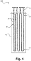
- Figure 1 schematically illustrates a reactor for carrying out a chemical reaction according to an embodiment not according to the invention.
- the reactor designated here by 300 is set up to carry out a chemical reaction.
- it has an in particular thermally insulated reactor vessel 10 and a reaction tube 20, a number of tube sections of the reaction tube 20, which are designated here by 21 only in two cases, each between a first zone 11 'and a second zone 12' in the Reactor vessel 10 run.
- the reaction tube 20, which will be described below with reference to FIG Figure 2 is explained in more detail, fastened with suitable suspensions 13.
- the reactor vessel can be in a lower area in particular have a not illustrated furnace. It goes without saying that a plurality of reaction tubes can be provided here and below.
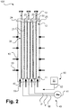
- Figure 2 schematically illustrates a reactor for carrying out a chemical reaction in accordance with an embodiment of the present invention, which is designated as a whole by 100.
- the zones previously designated 11 'and 12' are designed here as areas 11 and 12, with the pipe sections 21 for heating the pipe sections 21 in the first areas 11 each electrically connected to the phase connections U, V, W of a multiphase alternating current source 41 via connection elements 42 can be connected, whereby a total of 40 designated means for electrical heating of the reaction tube 20 are formed. Switches and the like and the specific type of connection are not illustrated.
- the pipe sections 21 are electrically conductively connected to one another in the second regions 12 by means of a connecting element 30 which is integrally connected to the one or more reaction tubes 20 and is arranged within the reactor vessel 10.
- a neutral conductor can also be connected to the connecting element 30.
- a star connection of several alternating current phases is implemented.
- the invention can also be provided using single-phase alternating current heating, direct current heating or other means of heating, for example for inductive or indirect heating in the sense explained above.
- a first group of reverse arcs 23 (bottom in the drawing) are arranged next to one another in the first area 11 and a second group of reverse arches 23 (top in the drawing) are arranged next to one another in the second area 12.
- the reverse arcs 23 of the second group are formed in the connecting element 30 and the pipe sections 21 extend from the connecting element 30 in the second area 12 to the first area 11.
- the power feed elements 52 can be designed as desired, for example rigid, and with rod-shaped sections through a wall of the Reactor container 10 step.
- Means for feeding an inerting gas into the reactor vessel are indicated by 50 in total. As illustrated by arrows 53 (only partially labeled accordingly), the inerting gas is fed into the reactor container 10 in particular via wall openings, nozzles or the like in one or more walls of the reactor container 10. To provide and feed in the inerting gas, suitable gas feed means are provided, which are also illustrated here in a greatly simplified manner and which comprise, for example, one or more gas tanks 51 and corresponding lines 52.
- Figure 3 schematically illustrates a reactor for carrying out a chemical reaction in accordance with an embodiment of the present invention, which is designated as a whole by 200.
- the pipe sections denoted here by 22 each comprise a pipe section 22 of a plurality of reaction tubes 20, the pipe sections 22 being fluidically unconnected next to one another in the reactor vessel 10 and each being connected to feed sections 24 and removal sections 25.
- connecting element 30 is optional within the scope of the present invention, although particularly advantageous when using a multiphase alternating current heater.
- power feed elements 42 are illustrated in a greatly simplified manner. The feeding of the inerting gas according to the arrows 53 takes place here as essentially explained above.
- the current feed elements 42 can have a collar-like area 43 attached to them, which in the first area 11 is placed around the reaction tubes 20 or the tube sections.
- the Figures 4 to 8 show partial views of reactors according to embodiments of the present invention in a simplified representation, a chimney 60 also being illustrated in each case.
- the gas feed means 50 for feeding in the inerting gas are not shown, nor are the means 40 for electrical heating.
- the reaction tube 20 is shown with reverse bends Figure 2 illustrated, but can also in any other form, for example according to Figure 3 be trained.
- a feed of inerting gas is indicated by an arrow 53 only at one point.
- the reactor vessel 10 has a permanently open outflow opening 61 connected to the chimney 60.
- the feed of inert gas and the high temperatures in the reactor vessel 10 opposite one end 63 of the chimney 60 results in a flow illustrated by arrows 64.
- the high temperatures lead to a static pressure p box in the reactor vessel, which is below atmospheric pressure p Atm in the adjacent environment, if the inerting gas is fed in in an adapted manner.
- the amount of purging gas chosen here is not too large. In the case of a very large amount of purging gas, the pressure loss in the chimney 60 would lead to the internal pressure in the reactor vessel 10 approaching or even exceeding the external pressure.
- this amount prevents ambient air from flowing back into the reactor vessel 10; In addition, minor air infiltration due to inadequate sealing is compensated for.
- the supply of inerting gas into the reactor vessel 10 can in particular be regulated via an oxygen measurement 65 in the chimney 60, so that the oxygen content can be kept constant during operation.
- the reactor vessel 10 according to Figure 5 operated at a pressure level above atmospheric, with a continuous feed of inerting gas into the reactor vessel 10 is made.
- the reactor vessel 10 has an opening above of a predetermined pressure level set up discharge opening 62, for example in the form of a bursting disc.
- the inerting gas supply compensates for small gas leaks into the atmosphere, which are illustrated here with an arrow 55.
- the flushing quantity can be regulated by measuring the pressure in the reactor vessel 10.
- a correspondingly dimensioned outlet opening to a safe place can be provided (in the area of the chimney 60 or another place that is not easily accessible and not endangering people) so that a flow 66 results from the reactor vessel 10.
- the reactor vessel 10 according to Figure 6 operated at a superatmospheric pressure level.
- the reactor vessel 10 has an outflow opening 62, for example in the form of a rupture disk, which is set up to open above a predetermined pressure level.
- the flow 66 does not develop in this embodiment.
- the oxygen content is preferably measured in the discharge of the purge gas downstream of the reactor container 10 (for example in the chimney 60 or another discharge line). Additionally or alternatively, the oxygen content can also be measured using suitable measuring methods (e.g. tunable diode laser, zirconium oxide probes, GC, paramagnet) be measured at one or more points in the area of the reactor vessel 10.
- suitable measuring methods e.g. tunable diode laser, zirconium oxide probes, GC, paramagnet
- the oxygen content can be measured analogously in a flushing gas discharge line that may be used for the initial inerting and / or in the reactor vessel 10 itself.
- the pressure inside the reactor vessel can be continuously measured and monitored in order to detect any impermissible loss of inert gas at an early stage.
- the chimney 60 in all of the configurations illustrated above can have structural elements (so-called velocity seals / confusors) in the area of the chimney wall in order to avoid air backflows (e.g. due to free convection currents) back to the reactor container 20.
- structural elements so-called velocity seals / confusors
- Figure 7 schematically illustrates a reactor for carrying out a chemical reaction according to an embodiment of the invention as an extension to the illustration according to the previous figures, with some of the elements already explained above not being illustrated again. For further explanation, reference is made in particular to the above Figure 4 referenced.
- ignition devices or pilot burners 68 can additionally be installed in the area of the chimney outlet 63 in order to at least partially prevent unburned hydrocarbons from escaping into the atmosphere in the event of an accident.
- the inerting gas can be fed into the reactor vessel 10 at different sides. A wall of the reactor vessel 10 and wall passages of fastenings or power supply devices are illustrated with 15, each of which can advantageously be made gas-tight. With I and O, process gas is fed in and the process gas is withdrawn from the reaction tube 20.
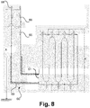
- FIG. 8 schematically illustrates a reactor for carrying out a chemical reaction according to an embodiment of the invention as an extension to the illustration according to FIG Figure 7 or a variant thereof.
- the chimney 60 can have suitable insulation 69 in an area adjoining the reactor vessel 10.
- the chimney 70 can have a height h of, for example, 20 to 50 meters above the ground.
- a so-called velocity seal 66 can be provided in the chimney 60.
- Figure 9 schematically illustrates the fundamentals of chimney dimensioning according to an embodiment of the present invention in the form of a diagram in which an oxygen content in percent is shown on the abscissa and a reaction-related rate of increase in volume in m 3 / s is shown on the ordinate.
- a graph 601 shows the relationship already explained above with reference to the table.
- a dashed line 602 denotes values required for a maximum pressure increase of 20 mbar with a chimney diameter of 500 mm
- a broken line 603 denotes corresponding values with a chimney diameter of 900 mm .
Landscapes
- Chemical & Material Sciences (AREA)
- Organic Chemistry (AREA)
- Chemical Kinetics & Catalysis (AREA)
- Health & Medical Sciences (AREA)
- General Health & Medical Sciences (AREA)
- Toxicology (AREA)
- Physical Or Chemical Processes And Apparatus (AREA)
- Devices And Processes Conducted In The Presence Of Fluids And Solid Particles (AREA)
Priority Applications (13)
| Application Number | Priority Date | Filing Date | Title |
|---|---|---|---|
| EP20171196.7A EP3900818A1 (fr) | 2020-04-23 | 2020-04-23 | Réacteur et procédé de réalisation d'une réaction chimique |
| EP21719925.6A EP4139035B1 (fr) | 2020-04-23 | 2021-04-22 | Réacteur et procédé de réalisation d'une réaction chimique |
| MYPI2022005920A MY210272A (en) | 2020-04-23 | 2021-04-22 | Reactor and method for carrying out a chemical reaction |
| JP2022564632A JP7731369B2 (ja) | 2020-04-23 | 2021-04-22 | 化学反応を実行するための反応器および方法 |
| HUE21719925A HUE064114T2 (hu) | 2020-04-23 | 2021-04-22 | Reaktor és eljárás kémiai reakció elvégzésére |
| US17/996,523 US12370519B2 (en) | 2020-04-23 | 2021-04-22 | Reactor and method for carrying out a chemical reaction |
| CN202180030189.7A CN115427139A (zh) | 2020-04-23 | 2021-04-22 | 用于进行化学反应的反应器和方法 |
| CA3179704A CA3179704A1 (fr) | 2020-04-23 | 2021-04-22 | Reacteur et procede pour la mise en oeuvre d'une reaction chimique |
| KR1020227041127A KR20230010207A (ko) | 2020-04-23 | 2021-04-22 | 반응조 및 화학반응 수행 방법 |
| PCT/EP2021/060601 WO2021214257A1 (fr) | 2020-04-23 | 2021-04-22 | Réacteur et procédé pour la mise en œuvre d'une réaction chimique |
| ES21719925T ES2967934T3 (es) | 2020-04-23 | 2021-04-22 | Reactor y método para llevar a cabo una reacción química |
| SA522441020A SA522441020B1 (ar) | 2020-04-23 | 2022-10-23 | مفاعل وطريقة لإجراء تفاعل كيميائي |
| ZA2022/12552A ZA202212552B (en) | 2020-04-23 | 2022-11-17 | Reactor and method for carrying out a chemical reaction |
Applications Claiming Priority (1)
| Application Number | Priority Date | Filing Date | Title |
|---|---|---|---|
| EP20171196.7A EP3900818A1 (fr) | 2020-04-23 | 2020-04-23 | Réacteur et procédé de réalisation d'une réaction chimique |
Publications (1)
| Publication Number | Publication Date |
|---|---|
| EP3900818A1 true EP3900818A1 (fr) | 2021-10-27 |
Family
ID=70470801
Family Applications (2)
| Application Number | Title | Priority Date | Filing Date |
|---|---|---|---|
| EP20171196.7A Withdrawn EP3900818A1 (fr) | 2020-04-23 | 2020-04-23 | Réacteur et procédé de réalisation d'une réaction chimique |
| EP21719925.6A Active EP4139035B1 (fr) | 2020-04-23 | 2021-04-22 | Réacteur et procédé de réalisation d'une réaction chimique |
Family Applications After (1)
| Application Number | Title | Priority Date | Filing Date |
|---|---|---|---|
| EP21719925.6A Active EP4139035B1 (fr) | 2020-04-23 | 2021-04-22 | Réacteur et procédé de réalisation d'une réaction chimique |
Country Status (12)
| Country | Link |
|---|---|
| US (1) | US12370519B2 (fr) |
| EP (2) | EP3900818A1 (fr) |
| JP (1) | JP7731369B2 (fr) |
| KR (1) | KR20230010207A (fr) |
| CN (1) | CN115427139A (fr) |
| CA (1) | CA3179704A1 (fr) |
| ES (1) | ES2967934T3 (fr) |
| HU (1) | HUE064114T2 (fr) |
| MY (1) | MY210272A (fr) |
| SA (1) | SA522441020B1 (fr) |
| WO (1) | WO2021214257A1 (fr) |
| ZA (1) | ZA202212552B (fr) |
Families Citing this family (4)
| Publication number | Priority date | Publication date | Assignee | Title |
|---|---|---|---|---|
| EP3878546A1 (fr) | 2020-03-13 | 2021-09-15 | Linde GmbH | Réacteur et procédé de réalisation d'une réaction chimique |
| EP3900817A1 (fr) | 2020-04-23 | 2021-10-27 | Linde GmbH | Réacteur et procédé de réalisation d'une réaction chimique |
| EP4316638A1 (fr) * | 2022-08-04 | 2024-02-07 | Linde GmbH | Procédé et installation pour la mise en oeuvre d'une réaction en phase gazeuse |
| EP4650043A1 (fr) * | 2024-05-15 | 2025-11-19 | Selas-Linde GmbH | Système de traitement de gaz et procédé de traitement d'un gaz |
Citations (6)
| Publication number | Priority date | Publication date | Assignee | Title |
|---|---|---|---|---|
| WO2004091773A1 (fr) * | 2003-04-15 | 2004-10-28 | Degussa Ag | Reacteur chauffe electriquement et procede de realisation de reactions gazeuses a haute temperature en utilisant ce reacteur |
| WO2015197181A1 (fr) | 2014-06-26 | 2015-12-30 | Linde Aktiengesellschaft | Dispositif et procédé de chauffage d'un fluide dans une conduite au moyen d'un courant triphasé |
| EP3075704A1 (fr) | 2015-03-31 | 2016-10-05 | Linde Aktiengesellschaft | Four pour le reformage a la vapeur d'hydrocarbures dote de tubes chauffables par combustion et electriquement |
| WO2017072057A1 (fr) | 2015-10-28 | 2017-05-04 | Haldor Topsøe A/S | Déshydrogénation d'alcanes |
| WO2019228798A1 (fr) | 2018-05-31 | 2019-12-05 | Haldor Topsøe A/S | Réactions endothermiques chauffées par chauffage par résistance |
| WO2020002326A1 (fr) | 2018-06-29 | 2020-01-02 | Shell Internationale Research Maatschappij B.V. | Réacteur chauffé électriquement et procédé de conversion de gaz utilisant ledit réacteur |
Family Cites Families (17)
| Publication number | Priority date | Publication date | Assignee | Title |
|---|---|---|---|---|
| GB265950A (en) * | 1926-02-15 | 1927-10-06 | British Thomson Houston Co Ltd | Improvements in and relating to electric furnaces |
| JPS4910026A (fr) | 1972-05-23 | 1974-01-29 | ||
| JPS5760398B2 (fr) * | 1974-01-14 | 1982-12-18 | Babcock Hitachi Kk | |
| JPS5223246A (en) | 1975-08-18 | 1977-02-22 | Sony Corp | Output circuit |
| JP3164662B2 (ja) * | 1992-09-22 | 2001-05-08 | 株式会社東芝 | 材料ガス供給管の加熱装置 |
| PL175410B1 (pl) | 1995-05-24 | 1998-12-31 | Karpinski Janusz | Urządzenie do przeprowadzania procesów technologicznych w wysokiej temperaturze i pod wysokim ciśnieniem |
| FR2747938B1 (fr) * | 1996-04-24 | 1998-10-02 | Naphtachimie Sa | Procede et dispositif de traitement thermique de produits circulant dans un conduit |
| FR2749921B1 (fr) * | 1996-06-14 | 1998-09-18 | Naphtachimie Sa | Procede et dispositif de mise en vibration d'un conduit dans une enceinte thermique |
| DE69904911D1 (de) | 1999-04-09 | 2003-02-20 | Jean Affolter | Verfahren und Vorrichtung zur Herstellung von Russ |
| RU2173213C1 (ru) | 2000-12-28 | 2001-09-10 | Зао "Тк Сибур Нн" | Устройство прямой термической конверсии метана |
| JP2006261362A (ja) | 2005-03-17 | 2006-09-28 | Hitachi Kokusai Electric Inc | 基板処理装置 |
| KR100661284B1 (ko) | 2006-02-14 | 2006-12-27 | 한국화학연구원 | 유동층 반응기를 이용한 다결정실리콘 제조 방법 |
| JP5634756B2 (ja) | 2010-06-08 | 2014-12-03 | 中部電力株式会社 | 防爆構造誘導加熱装置 |
| CN202208694U (zh) * | 2011-09-09 | 2012-05-02 | 可利亚多元醇(南京)有限公司 | 聚合物聚醚多元醇引发剂的加入装置 |
| JP5839915B2 (ja) | 2011-09-22 | 2016-01-06 | 三菱重工業株式会社 | 六フッ化硫黄分解処理装置及び方法 |
| CN205700113U (zh) * | 2016-02-19 | 2016-11-23 | 河北众鑫环保设备有限公司 | 安全型sncr脱硝装置 |
| KR20210042969A (ko) * | 2018-08-16 | 2021-04-20 | 바스프 에스이 | 직류 전류에 의해 파이프라인에서 유체를 가열하기 위한 디바이스 및 방법 |
-
2020
- 2020-04-23 EP EP20171196.7A patent/EP3900818A1/fr not_active Withdrawn
-
2021
- 2021-04-22 CA CA3179704A patent/CA3179704A1/fr active Pending
- 2021-04-22 MY MYPI2022005920A patent/MY210272A/en unknown
- 2021-04-22 KR KR1020227041127A patent/KR20230010207A/ko active Pending
- 2021-04-22 JP JP2022564632A patent/JP7731369B2/ja active Active
- 2021-04-22 ES ES21719925T patent/ES2967934T3/es active Active
- 2021-04-22 WO PCT/EP2021/060601 patent/WO2021214257A1/fr not_active Ceased
- 2021-04-22 US US17/996,523 patent/US12370519B2/en active Active
- 2021-04-22 HU HUE21719925A patent/HUE064114T2/hu unknown
- 2021-04-22 EP EP21719925.6A patent/EP4139035B1/fr active Active
- 2021-04-22 CN CN202180030189.7A patent/CN115427139A/zh active Pending
-
2022
- 2022-10-23 SA SA522441020A patent/SA522441020B1/ar unknown
- 2022-11-17 ZA ZA2022/12552A patent/ZA202212552B/en unknown
Patent Citations (7)
| Publication number | Priority date | Publication date | Assignee | Title |
|---|---|---|---|---|
| WO2004091773A1 (fr) * | 2003-04-15 | 2004-10-28 | Degussa Ag | Reacteur chauffe electriquement et procede de realisation de reactions gazeuses a haute temperature en utilisant ce reacteur |
| WO2015197181A1 (fr) | 2014-06-26 | 2015-12-30 | Linde Aktiengesellschaft | Dispositif et procédé de chauffage d'un fluide dans une conduite au moyen d'un courant triphasé |
| EP3075704A1 (fr) | 2015-03-31 | 2016-10-05 | Linde Aktiengesellschaft | Four pour le reformage a la vapeur d'hydrocarbures dote de tubes chauffables par combustion et electriquement |
| DE102015004121A1 (de) | 2015-03-31 | 2016-10-06 | Linde Aktiengesellschaft | Ofen mit elektrisch sowie mittels Brennstoff beheizbaren Reaktorrohren zur Dampfreformierung eines kohlenwasserstoffhaltigen Einsatzes |
| WO2017072057A1 (fr) | 2015-10-28 | 2017-05-04 | Haldor Topsøe A/S | Déshydrogénation d'alcanes |
| WO2019228798A1 (fr) | 2018-05-31 | 2019-12-05 | Haldor Topsøe A/S | Réactions endothermiques chauffées par chauffage par résistance |
| WO2020002326A1 (fr) | 2018-06-29 | 2020-01-02 | Shell Internationale Research Maatschappij B.V. | Réacteur chauffé électriquement et procédé de conversion de gaz utilisant ledit réacteur |
Non-Patent Citations (1)
| Title |
|---|
| ULLMANN'S ENCYCLOPEDIA OF INDUSTRIAL CHEMISTRY, BEISPIELSWEISE DIE PUBLIKATIONEN VOM, 15 April 2009 (2009-04-15) |
Also Published As
| Publication number | Publication date |
|---|---|
| MY210272A (en) | 2025-09-08 |
| CA3179704A1 (fr) | 2021-10-28 |
| SA522441020B1 (ar) | 2024-04-16 |
| EP4139035B1 (fr) | 2023-10-25 |
| JP7731369B2 (ja) | 2025-08-29 |
| KR20230010207A (ko) | 2023-01-18 |
| JP2023529785A (ja) | 2023-07-12 |
| US12370519B2 (en) | 2025-07-29 |
| ES2967934T3 (es) | 2024-05-06 |
| EP4139035A1 (fr) | 2023-03-01 |
| HUE064114T2 (hu) | 2024-02-28 |
| US20230211305A1 (en) | 2023-07-06 |
| WO2021214257A1 (fr) | 2021-10-28 |
| ZA202212552B (en) | 2025-02-26 |
| CN115427139A (zh) | 2022-12-02 |
Similar Documents
| Publication | Publication Date | Title |
|---|---|---|
| EP4139035B1 (fr) | Réacteur et procédé de réalisation d'une réaction chimique | |
| EP4139036B1 (fr) | Réacteur et procédé de réalisation d'une réaction chimique | |
| EP4117811B1 (fr) | Réacteur et procédé de réalisation d'une réaction chimique | |
| DE10317197A1 (de) | Elektrisch beheizter Reaktor und Verfahren zur Durchführung von Gasreaktionen bei hoher Temperatur unter Verwendung dieses Reaktors | |
| WO2009074228A2 (fr) | Élément recombineur | |
| WO2010063448A1 (fr) | Dispositif et procédé pour réactions catalytiques en phase gazeuse et leur utilisation | |
| DE69614632T2 (de) | Brenstoffprozessapparat mit ofen für brennstofzellenkraftanlage | |
| WO2000019449A2 (fr) | Procede et dispositif pour recombiner de l'hydrogene et de l'oxygene dans un melange gazeux | |
| EP0056830A1 (fr) | Procédé pour éviter ou pour diminuer le risque que court une installation et son environnement à cause de mélanges en réaction | |
| DE102014007470A1 (de) | Verfahren und Vorrichtung zur Dampfreformierung sowie zur Dampfspaltung von Kohlenwasserstoffen | |
| AT523668A1 (de) | Brennstoffzellensystem und Verfahren zum Betreiben eines Brennstoffzellensystems | |
| EP2456844A2 (fr) | Procédé pour faire fonctionner une unité d'injection | |
| DE19708738C1 (de) | Vorrichtung zum Beseitigen von Wasserstoff | |
| DE19513779A1 (de) | FCC (FLUID-CATALYTIC-CRACKING) -Anlage | |
| DE855242C (de) | Ofen zur Behandlung stroemender Reaktionsteilnehmer | |
| AT520881B1 (de) | Verfahren zum Betreiben eines Brennstoffzellensystems | |
| DE102014015948B4 (de) | Sicherheitszündvorrichtung | |
| DE102014018376A1 (de) | Verfahren und Vorrichtung zur Einleitung reaktiver Gase in einen Reaktionsraum | |
| WO2024125896A1 (fr) | Système de turbine à vapeur et condenseur/échangeur de chaleur pour un tel système de turbine à vapeur | |
| EP3035431B1 (fr) | Module de piles a combustible et procede de fonctionnement d'un module de piles a combustible | |
| DE102020122350A1 (de) | Verbrennungsvorrichtung und brennstoffzellen-modul | |
| DE102024125715A1 (de) | Prozessvorrichtung zur thermischen oder/und chemothermischen Behandlung von Prozessmaterial sowie Verfahren zur Bereitstellung eines Prozessgases | |
| DE1235494B (de) | Reformiervorrichtung mit an den unteren Enden geschlossenen Reformierrohren | |
| EP4585558A1 (fr) | Procédé et installation de fabrication d'un produit de processus | |
| EP3296629A1 (fr) | Procede et four a combustion destine a transformer de l'hydrogene et de l'oxygene atmospherique en eau ou de hho en eau |
Legal Events
| Date | Code | Title | Description |
|---|---|---|---|
| PUAI | Public reference made under article 153(3) epc to a published international application that has entered the european phase |
Free format text: ORIGINAL CODE: 0009012 |
|
| STAA | Information on the status of an ep patent application or granted ep patent |
Free format text: STATUS: THE APPLICATION HAS BEEN PUBLISHED |
|
| AK | Designated contracting states |
Kind code of ref document: A1 Designated state(s): AL AT BE BG CH CY CZ DE DK EE ES FI FR GB GR HR HU IE IS IT LI LT LU LV MC MK MT NL NO PL PT RO RS SE SI SK SM TR |
|
| B565 | Issuance of search results under rule 164(2) epc |
Effective date: 20200929 |
|
| STAA | Information on the status of an ep patent application or granted ep patent |
Free format text: STATUS: THE APPLICATION IS DEEMED TO BE WITHDRAWN |
|
| 18D | Application deemed to be withdrawn |
Effective date: 20220429 |