EP3900849A2 - Système de tri optique destiné au tri des particules granulaires - Google Patents
Système de tri optique destiné au tri des particules granulaires Download PDFInfo
- Publication number
- EP3900849A2 EP3900849A2 EP21167660.6A EP21167660A EP3900849A2 EP 3900849 A2 EP3900849 A2 EP 3900849A2 EP 21167660 A EP21167660 A EP 21167660A EP 3900849 A2 EP3900849 A2 EP 3900849A2
- Authority
- EP
- European Patent Office
- Prior art keywords
- conveyor belt
- granulate
- particles
- granulate particles
- sorting system
- Prior art date
- Legal status (The legal status is an assumption and is not a legal conclusion. Google has not performed a legal analysis and makes no representation as to the accuracy of the status listed.)
- Granted
Links
Images

Classifications
-
- B—PERFORMING OPERATIONS; TRANSPORTING
- B07—SEPARATING SOLIDS FROM SOLIDS; SORTING
- B07C—POSTAL SORTING; SORTING INDIVIDUAL ARTICLES, OR BULK MATERIAL FIT TO BE SORTED PIECE-MEAL, e.g. BY PICKING
- B07C5/00—Sorting according to a characteristic or feature of the articles or material being sorted, e.g. by control effected by devices which detect or measure such characteristic or feature; Sorting by manually actuated devices, e.g. switches
- B07C5/34—Sorting according to other particular properties
- B07C5/342—Sorting according to other particular properties according to optical properties, e.g. colour
- B07C5/3425—Sorting according to other particular properties according to optical properties, e.g. colour of granular material, e.g. ore particles, grain
-
- B—PERFORMING OPERATIONS; TRANSPORTING
- B07—SEPARATING SOLIDS FROM SOLIDS; SORTING
- B07C—POSTAL SORTING; SORTING INDIVIDUAL ARTICLES, OR BULK MATERIAL FIT TO BE SORTED PIECE-MEAL, e.g. BY PICKING
- B07C5/00—Sorting according to a characteristic or feature of the articles or material being sorted, e.g. by control effected by devices which detect or measure such characteristic or feature; Sorting by manually actuated devices, e.g. switches
- B07C5/02—Measures preceding sorting, e.g. arranging articles in a stream orientating
-
- B—PERFORMING OPERATIONS; TRANSPORTING
- B07—SEPARATING SOLIDS FROM SOLIDS; SORTING
- B07B—SEPARATING SOLIDS FROM SOLIDS BY SIEVING, SCREENING, SIFTING OR BY USING GAS CURRENTS; SEPARATING BY OTHER DRY METHODS APPLICABLE TO BULK MATERIAL, e.g. LOOSE ARTICLES FIT TO BE HANDLED LIKE BULK MATERIAL
- B07B2201/00—Details applicable to machines for screening using sieves or gratings
- B07B2201/04—Multiple deck screening devices comprising one or more superimposed screens
Definitions
- Optical sorting systems for sorting granulate particles are known from the prior art, wherein granulate particles supplied by means of the sorting systems can be divided or sorted at least into a first and second granulate fraction.
- the optical sorting systems known from the prior art usually have a metering chute for transferring the granulate particles to be sorted onto a conveyor belt, via which the particles to be sorted can be applied to the conveyor belt using gravity.
- optical sorting systems known from the prior art have the disadvantage that an uncontrolled amount of granulate particles is placed on the conveyor belt in such a way that it is not ensured that on the Conveyor belt only a monolayer of granulate particles is applied by means of the dosing chute.
- discharge devices known from the prior art which are implemented by means of air pulses and shovel devices, are imprecise and do not allow the exact discharge of deviating particles.
- the object of the present invention is to improve the known optical sorting systems to enable reliable detection and discharge of the granulate particles to be repelled, as well as to reduce the space required for the optical sorting system and to increase its sorting speed.
- an optical sorting system for sorting granulate particles into at least a first and second granulate fraction
- the optical sorting system comprising a metering device, a conveyor belt, an optical sensor device, a discharge device, a control device and at least one first and second granulate fraction outlet.
- the granulate particles are applied to the conveyor belt in a monolayer via the metering device, accelerated to a defined speed by means of the conveyor belt, ejected from the conveyor belt at a discharge end and transferred into a first free trajectory, with the optical sensor device making optical recordings the granulate particles are generated in the area of the discharge end, preferably after the discharge, and transmitted to the control device, the control device assigning the granulate particles to the at least one first or second granulate fraction on the basis of the optical recordings while evaluating at least one detection criterion and, when assigning a granulate particle, to the second Granulate fraction a control pulse is transmitted to the discharge device, wherein in the area of the free flight path the granulate particles are arranged at a defined distance from the discharge end of the first granulate fraction outlet, and where at Transmission of a control pulse, the discharge device transfers the granulate particles assigned to the at least one second granulate fraction into at least one second trajectory before reaching the first granulate fraction outlet and discharges it into at
- the granulate particles are applied to the conveyor belt at a first end opposite the discharge end.
- the granulate particles are applied to the conveyor belt via a metering device, by means of which a defined amount of granulate particles is applied to the conveyor belt per unit of time.
- the amount of granulate particles applied via the metering device per unit of time is controlled in such a way that a monolayer of the granulate particles is applied to or generated on the conveyor belt.
- a monolayer is understood to mean a distribution of the granulate particles on the conveyor belt in which there is no overlap between the granulate particles on the conveyor belt.
- the granulate particles are therefore not on top of one another on the conveyor belt, but rather at a distance from one another or touch one another.
- the granulate particles are pre-screened through an upstream screening device before being applied to the conveyor belt, metallic foreign particles in the granulate are removed by means of a metal separator and, if necessary, the granulate particles are electrostatically discharged before being applied to the conveyor belt by means of at least one ionizer. Furthermore, it can be provided that the granulate particles are freed from dust particles by means of a countercurrent wind sifting device before they are applied to the conveyor belt.
- the aforementioned pretreatment steps ensure that only granulate particles pass through the detection area of the optical sorting system, which can be reliably detected and do not leave any damage or contamination in the area of the optical sensor device or the discharge device.
- the granulate particles When thrown from the conveyor belt, the granulate particles are transferred into a first free trajectory with an idealized theoretical free trajectory parabola.
- the granulate particles When the granulate particles pass from the conveyor belt into the free flight path, they initially only have the conveyor belt speed, which at the same time represents the initial flight speed of the particles.
- two forces affecting the flight path act on the granulate particles along the first free trajectory: the air resistance and, in addition, the force of gravity or gravity - the theoretical or idealized parabolic trajectory of the granulate particles after being thrown from the conveyor belt.
- the optical recordings of the granulate particles are produced at the smallest possible distance from the discharge line of the granulate particles from the conveyor belt.
- This embodiment has the The advantage of a low scattering of the trajectory of the granulate particles at the detection point, so that the depth of focus of the sensor device is given with simultaneous optimal illumination over the background.
- the provided conveyor belt extends as a circulating, quasi-endless conveyor belt along the running direction of the conveyor belt from a first deflection device in the area of the end at which the granulate particles are placed on the conveyor belt to a second deflection device at the discharge end at which the granulate particles are removed from the conveyor belt Conveyor belt transferred into a free trajectory and thus thrown off.
- a third deflection device below the second deflection device, offset in the direction of the first deflection device, there is also a third deflection device, which enables an oblique return of the tape.
- the conveyor belt has essentially a flat conveyor belt surface with a flat surface profile in the direction of the conveyor belt.
- the conveyor belt can be bounded laterally by opposing bands in order to prevent the granulate particles from being thrown off or lost from the side and to allow the granulate particles to rebound on the belt surfaces.
- the two opposite lateral edges of the conveyor belt run at a small distance from the side plates.
- the distance between the side plates and the edge of the conveyor belt creates an air gap through which a fluid stream can flow or be ejected.
- the opposing bands which laterally delimit the conveyor belt, are arranged parallel to the plane of the conveyor belt surface at a small distance above the conveyor belt surface.
- the two opposite bands are each arranged at a distance from the two opposite side plates via corresponding spacers.
- the distance between the respective side plate and the band can be adjusted via a displaceably configured spacer, in such a way that the resulting Conveyor belt width is adjustable or finely adjustable via the spacer.
- the provision of fastening the bands via the spacers enables the air flow, which is carried out between the conveyor belt and the side plates, to be passed through to the area above the respective bands or the conveyor belt.
- the conveyor belt In the area of the deflection device on the discharge side, the conveyor belt is transferred in the running direction from the flat course to a surface course that is convex in the running direction of the conveyor belt.
- the transition between the flat and convex course forms a transition line transversely or orthogonally to the running direction of the conveyor belt, which is referred to as the throw-off line, at which the granulate particles change from the state resting on the conveyor belt into a free trajectory.
- the surface of the conveyor belt thus curves in the area of the discharge end essentially away from the horizontal running direction downwards.
- the discharge device can deflect at least one granulate particle from the free flight path by emitting at least one air pulse, or give it a desired speed vector with a defined amount of speed and a defined direction.
- the resulting speed vector is selected in such a way that it deviates from the speed vector of the granulate particle along the free flight path and guides or transfers the at least one particle into a second flight path which deviates from the first flight path.
- the use of air pulses in the area of the discharge device to deflect the granulate particles from the free trajectory has the advantage that particles can be deflected again and again by the discharge device at very short time intervals without influencing the subsequent particles during ejection.
- the at least one particle to be discharged is accelerated by the discharge device compared to the current speed on the first free flight path and, after application of the air pulse, has an increased or at least the same speed compared to the speed on the first free flight path.
- the magnitude of the speed can be accelerated in the direction of the trajectory of the granulate particle. The acceleration of the ejected particles compared to the airspeed on the free flight path prevents subsequent particles from hitting the ejected particles, as a result of which a build-up of the particles due to the particle ejection can be avoided.
- the transport path along the conveyor belt and in particular the conveyor belt surface can run essentially along a flat plane which is oriented approximately orthogonally to the vector of the gravitational force and thus essentially horizontally.
- the alignment of the conveyor belt or the conveyor belt surface essentially along a flat plane, which runs essentially orthogonally to the vector of gravity, has the advantage that the particles placed on the conveyor belt can calm down or settle relatively quickly after being placed on the conveyor belt can reduce their kinetic energy relatively quickly due to the task on the conveyor belt, in such a way that the particles only have the conveyor belt speed at least in the area of the discharge end. In particular, it is avoided that the particles slide off the conveyor belt due to their own weight at the discharge end and thus have an uncontrolled additional amount of speed.
- the granulate particles are moved along the transport path from the first end of the conveyor belt, at which the granulate particles are placed on the conveyor belt, to the discharge end accelerated to the sorting speed, which corresponds to the conveyor belt speed.
- the at least one granulate particle is deflected by the discharge device by means of at least one air pulse in such a way that the granulate particle, which was assigned to the at least one second granulate fraction, is discharged into the at least one second fraction outlet.
- the granulate particles to be sorted are sorted into a first and a second granulate fraction.
- the first granulate fraction is preferably the so-called good fraction into which the granulate particles are sorted which meet the required quality criteria and therefore do not have any defects.
- the first granulate fraction arrives along the parabola of the free trajectory after being dropped from the conveyor belt without additional interventions in the first granulate fraction outlet.
- the second granulate fraction is what is known as the rejection fraction, which does not meet the required quality criteria and has, for example, defects such as color deviations, inclusions or deviations in shape.
- the granulate particles which do not meet the required quality criteria are assigned to the second granulate fraction by means of the sensor device by evaluating at least one detection criterion and then transferred to a second trajectory deviating from the first free trajectory by means of the discharge device, the granulate particle which was assigned to the rejection fraction , is transferred to the second granulate fraction outlet.
- the granulate particles can still be assigned to a plurality of first or second granulate fraction outlets on the basis of a plurality of detection criteria.
- the optical sensor device generates recordings of the granulate particles in the area of the free flight path, the recordings being at a horizontal distance relative to a throw line of the conveyor belt on which the granulate particles are thrown off, in the range of 5 mm to 40 mm, preferably in the range from 5 mm to 15 mm.
- the optical sensor device it is also possible to use the optical sensor device to generate recordings of the granulate particles lying on the conveyor belt in the transport direction in front of the discharge line in the region of the discharge end of the conveyor belt, the recordings preferably at a horizontal distance in the range of 5 mm to 40 mm, preferably in the range from 5 mm to 15 mm, generated from the drop end.
- the arrangement of the optical sensor device for generating the recording directly behind the discharge line of the conveyor belt has the advantage that the granulate particles to be detected in the above-described detection area have only slight scatter in the trajectory, such that the sensor device focuses very precisely on the trajectory of the granulate particles or can be aligned.
- the generation of the optical recordings lying on the conveyor belt directly in the area in front of the discharge line has the advantage that the particles are guided in a defined detection plane in such a way that the optical detection device can be precisely aligned and focused on the particles to be detected.
- Another advantage of the detection of the granulate particles lying on the conveyor belt is that the particles have a defined background in the form of the conveyor belt or the conveyor belt surface.
- the sensor device comprises a central visual axis, the visual axis with the tangent of the free flight path at the intersection of the visual axis with the free flight path at an angle in the range of 75 ° to 115 °, preferably in Range from 85 ° to 95 °.
- the middle line of sight of the sensor device is defined by the sensor elements of the sensor device in connection with the optical beam path by an optics of the sensor device upstream of the sensor elements.
- the sensor device can be configured as a line sensor by a plurality of individual sensors arranged in a row or alternatively as a two-dimensional area sensor with a plurality of individual sensors arranged next to one another in a sensor matrix in columns and rows.
- the individual sensors can be referred to as pixels.
- the middle line of sight in the area of the individual sensors is defined as a straight line which runs orthogonally to the plane of the individual sensors and intersects it in the center of the individual sensors.
- the visual axis can be deflected by the optics upstream of the individual image sensors and influenced accordingly.
- the sensor device can be a CMOS sensor or a CCD sensor, which is focused on a specific detection area by means of optics upstream of the sensor.
- the visual axis runs from the focus area through the optics to the sensor elements of the sensor device.
- the sensor elements of the sensor device are formed by several commercially available CMOS sensors or CCD sensors.
- the angle between the visual axis and the tangent of the free flight path is measured in a plane transverse to the flight direction or flight path of the granulate particles, the angle between the visual axis and the tangent being determined on the side facing away from the discharge end.
- the sensor device can generate recordings of the thrown granulate particles at a frequency in the range from 36 kHz to 150 kHz.
- the design of the sensor device with a frequency in the range from 36 kHz to 150 kHz enables a flow of granulate particles at a very high speed over the to detect optical sensor device and thus make it accessible for optical sorting.
- the image recorded by the sensor device particularly preferably has a resolution in the range from 10 ⁇ m to 50 ⁇ m, preferably 15 ⁇ m or 25 ⁇ m, per pixel or individual image sensor.
- the high resolution makes it possible to resolve and examine very small errors (artifacts) by means of the optical detection device.
- the discharge device is arranged in the area of the free trajectory of the granulate particles at a horizontal distance relative to the detection line in a distance range of 2 cm to 9 cm, preferably in the range of 2 cm to 5 cm is.
- the arrangement of the discharge device in the described areas and thus very close behind the discharge end has the advantage that the free trajectory of the granulate particles in this area still has a relatively low scatter, so that the granulate particles approximately still have the idealized, theoretically calculated trajectory and so that the location of each granulate particle can be reliably determined via the airspeed and the distance of the discharge device relative to the detection line. This in turn makes it possible to prevent incorrect ejection of the discharge device and to reliably eject the detected particles with errors or deviations without influencing further particles.
- a lighting device is arranged above and / or below the free trajectory of the granulate particles for illuminating the granulate particles.
- the lighting device comprises at least one light source, in particular a light-emitting diode. Furthermore, provision can be made for the lighting intensity and the lighting color, in particular the wavelength or the color spectrum of the lighting device, to be actively set and changed by means of control electronics. By controlling the lighting intensity or the lighting color or the wavelength of the emitted light, the optical sorting system according to the invention can be adapted to the granulate particles to be sorted and their color or their optical properties.
- the lighting device can be arranged at a distance in the horizontal direction from the discharge line of the conveyor belt in the range from -40 to 40 mm, preferably in the range -40 to 15 mm, particularly preferably centrally above the detection line.
- the negative values correspond to a distance in the direction of transport in front of the discharge line, positive values to a distance in the direction of flight behind the discharge line.
- a lighting background is arranged opposite in the direction of the light beams emitted by the lighting device relative to the free trajectory of the granulate particles.
- the lighting background enables optical recordings of the granulate particles to be detected to be photographed with a known and defined background, in particular a known background color or known background structure. This makes it possible to reliably detect color deviations or other artifacts in the particles to be detected.
- the arrangement of the lighting background when generating the optical recordings prevents the particle from capturing additional scattered light from the environment and thus optical artifacts from being reflected in the granulate particles to be detected, which in turn could lead to optical misinterpretations.
- the lighting background is also actively illuminated, with the lighting intensity and the lighting color or also the wavelength of the lighting background being actively controllable.
- the lighting background can also be designed as a passive background surface, which is preferably adapted to the color of the granulate particles.
- the separating sword comprising a face in the form of a sharp knife edge which tapers to a point relative to the discharging end can.
- a tapering end face in the form of a knife edge ensures that the granules that hit there are deformed (energy absorption) and thus do not result in granulate particles that rebound directly into the first free trajectory, which could interfere with the sorting process or cause a particle jam in the area of the granulate outlets or optical sorting.
- the at least one dividing sword is designed essentially as a dividing wall and can comprise a flat or curved surface course in the plane to the discharge corridor, which preferably runs parallel to the first flight path, the at least one partition wall preferably being arranged at a defined distance below the flight path.
- a longitudinal axis of the cutting blade relative to the tangent to the first idealized trajectory of the granulate particles in the Intersection between the longitudinal axis of the separating sword of the first trajectory is arranged to include an angle in the range from 5 ° to 45 °.
- the separating sword is arranged to be displaceable along its longitudinal axis in order to adapt it to the trajectory of the granules.
- the end face of the separating sword can have a horizontal distance relative to the detection line in the range from 10 to 80 mm.
- the metering device comprises at least a first and a second sieve deck, the granulate particles being passed over the sieve covers, whereby granulate particles above a second mean particle diameter are separated by means of the first sieve deck and the granulate particles below a first mean particle diameter are separated by the second sieve deck are separated, in such a way that granulate particles with an average particle diameter between the first and second particle diameter are fed to the conveyor belt.
- the two screen decks ensure that only granulate particles with an average particle diameter in a defined area between a first and a second diameter are fed to the conveyor belt.
- the metering device further comprises at least one metering channel, via which the granules are applied after passing through the sieve deck and via which the granules are fed onto the conveyor belt.
- the metering channel can be designed as a flat surface and is oriented essentially horizontally and also has a small distance, preferably a distance in the vertical direction that is smaller than the mean particle diameter, relative to the conveyor belt surface.
- the metering device running along a horizontal plane which is at a small distance in the vertical direction from the conveyor belt or the conveyor belt surface, has the advantage that the granulate particles fed onto the conveyor belt via the metering device only have a low initial energy (potential energy and kinetic energy) , which makes it possible to quickly calm down the granulate particles on the conveyor belt.
- the dosing chute at a discharge end of the dosing chute at which the granulate particles are fed from the dosing chute onto the conveyor belt has essentially the width of the conveyor belt.
- it can also be provided to provide several metering chutes across the width of the conveyor belt.
- the metering device additionally comprises a vibration device, by means of which the screen decks and / or the metering channel can be made to vibrate.
- the oscillation amplitude, the shape and orientation of the oscillation amplitude and also the frequency of the oscillation amplitude of the vibration device can be set flexibly.
- the granulate particles to be fed onto the conveyor belt being passed through the two offset ionization devices before being fed onto the conveyor belt.
- the longitudinal axes of the ionization devices run essentially orthogonally to the longitudinal axis of the conveyor belt. Due to the offset arrangement of the ionization devices, any electrical charges that may still be present on the granulate particles can be dissipated from them in such a way that they are essentially discharged uncharged by the dosing device onto the conveyor belt in order to avoid possible repulsions or attraction effects of the granulate particles due to electrical charges present on the acceleration belt and to prevent free flight.
- the ambient air is locally ionized or electrically charged by means of the ionization device in such a way that electrical charges on the granulate particles can be diverted from the granulate particles by the ionized air.
- the discharge device is formed by a multiplicity of individual nozzles which are arranged above or below the free trajectory of the particles.
- an air guiding device or several air guiding devices can be arranged in front of the individual nozzles of the discharge device, the air flow ejected by the individual nozzles being diverted in a defined direction via the air guiding device.
- the air flow ejected by the individual nozzle and diverted via the air guiding device has a horizontal speed of at least 1.5 m / s.
- the horizontal speed component is adapted to the conveyor belt speed or the current particle flight speed at the time of passage through the discharge device.
- a compensating air duct extending from the second fraction outlet in the horizontal direction is arranged, the compensating air duct being formed by a bottom plate and two opposite side plates is formed as an upwardly open channel and wherein the bottom plate is formed falling in the direction of the second fraction outlet.
- the base plate has an angle in the range from 0 to 25 ° with respect to a horizontal line.
- the at least one second fraction outlet comprises a lateral opening in a wall of the outlet, the opening being covered with an air-permeable filter device.
- the conveyor belt is formed from an electrostatically conductive belt material or the conveyor belt comprises electrostatically conductive belt material.
- the conveyor belt can have a deflecting edge with a radius of the conveyor belt surface of less than 20 mm, in particular of less than 10 mm.
- the conveyor belt comprises a belt material in which reinforcing fibers, such as in particular carbon fibers, are embedded in the running direction of the conveyor belt.
- the conveyor belt is designed as a revolving endless belt, the conveyor belt comprising two belt ends which are connected via a toothed weld seam are connected to one another and wherein the weld seam has an angle in the range from 35 to 55 °, particularly preferably an angle of 45 °, relative to the running direction of the conveyor belt.
- the conveyor belt comprises a conveyor belt surface for the transport of the particles, the conveyor belt surface having a low surface roughness, particularly preferably 0.2 ⁇ m.
- the absolute numerical value of the length of the transport path of the granulate particles along the conveyor belt corresponds to the absolute numerical value of the running speed of the conveyor belt, measured in m / s.
- the conveyor belt is driven at a running speed in the range from 1 m / s to 3 m / s, particularly preferably in the range from 1.5 m / s to 2.5 m / s.
- the Fig. 1 shows a schematic side sectional view of an embodiment of a sorting system according to the invention.
- the granulate particles 100 to be sorted are fed to the optical sorting system at an upper end of the optical sorting system via a material inlet 1 and are sorted into two granulate fractions 1 by the exemplary optical sorting system shown.
- the first granulate fraction is the so-called good fraction, whereby the granulate particles 100 in the first granulate fraction correspond to the quality criteria set and are discharged from the optical sorting system via the first granulate fraction outlet 21, whereas the granulate particles 100 which do not meet the required quality criteria are discharged from the optical sorting system the second granulate fraction outlet 22 can be discharged from the optical sorting system.
- a countercurrent wind sifter 2 Downstream of the material inlet 1, a countercurrent wind sifter 2 is initially arranged for presorting the granulate particles 100 before they are placed on the conveyor belt 7, via which possible dust particles can be separated from the granulate particles 100 to be sorted. Furthermore, an all-metal separator 3 is arranged downstream of the countercurrent wind sifter 2, via which possible metal particles can be removed from the granulate particles 100 supplied. Following the all-metal separator 3 is the metering device 4, via which the granulate particles 100 are applied to the conveyor belt 7 according to the invention. In the area of the discharge end 7b of the conveyor belt 7, an optical sensor device 9 and a lighting device 10 as well as a discharge device 12 are arranged. Furthermore, in the exemplary embodiment shown, a separating sword 11 was arranged in the area of the free trajectory 201 of the granulate particles 100 to separate the first granulate fraction outlet 21 and the second granulate fraction outlet 22.
- compensating air duct 221 outgoing essentially in the horizontal direction, the compensating air duct 221 being delimited laterally and at the bottom by a bottom plate 222 and two opposite side plates 223.
- the compensating air duct 221 is designed as a duct which is open at the top and from which air can exit.
- the compensating air duct 221 serves to reduce the volume and air velocity of the air expelled by the discharge device 12 in such a way that no dynamic pressure arises in the second fraction duct 22.
- the bottom plate 222 is designed to be sloping in the direction of the second fraction outlet 22 or to rise as the distance from the second fraction outlet 22 increases.
- the floor panel 222 has an angle ⁇ with respect to an imaginary horizontal.
- the second fraction outlet 22 has a lateral opening 220 which is provided in a wall of the outlet 22, the opening 220 being covered with an air-permeable filter device 224.
- the air-permeable filter device 224 enables the air flow emitted via the discharge device 12 to be discharged in the region of the second outlet 22 via the lateral opening 220.
- the air-permeable filter device 224 prevents granulate particles 100 in the area of the second granulate fraction outlet from being discharged via the lateral opening 220 and, in particular, when a compensating air duct 221 is arranged, not being introduced into it.
- the conveyor belt 7 runs in the compensating air duct 221, which is open at the top, the side edges of the conveyor belt 7 running at a distance from the side plates 223. Through the gap between the side plates 223 and the conveyor belt 7, the air introduced into the compensating air duct 221 is discharged laterally upwards on the conveyor belt.
- This embodiment has the advantage that the volume of air introduced by the discharge device 12 can be discharged so that no dynamic pressure arises.
- Belts can be arranged on the two side plates 223 via spacers (not shown) which laterally delimit the conveyor belt surface of the conveyor belt 7 and prevent the transported granulate particles 100 from being thrown off to the side.
- the conveyor belt 7 can be designed as a revolving endless belt, a conveyor belt surface 7s being provided for the transport of the granulate particles 100, which surface preferably has a low surface roughness.
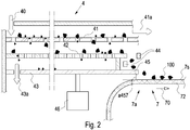
- the Fig. 2 shows a schematic view of an exemplary embodiment of a metering device 4 according to the invention and its arrangement in the area of the feed end 7a of a conveyor belt 7 of an optical sorting system according to the invention.
- the metering device 4 shown here has an upper material feed 40 in which the granulate particles 100 are transferred to the metering device.
- the metering device 4 shown has a first screen deck 41 and a second screen deck 42 arranged below it, as well as a bottom plate 43 and a metering channel 45 the granulate particles 100 are separated above a second mean particle diameter and the excessively large particles are removed from the optical sorting system via an ejection 41a in such a way that they are no longer fed to the conveyor belt 7.
- the granulate particles 100 which have a mean diameter below the second mean particle diameter, fall through the openings of the first sieve deck 41 onto the second sieve deck 42 below, the granulate particles 100 below a first mean particle diameter being separated by means of the second sieve deck 42 and via an ejection 43a in the base plate 43 are discharged from the metering device 4.
- the particles with a diameter that is too small and discharged via the ejection 43a are also removed from the optical sorting system in such a way that they are no longer fed to the conveyor belt 7 either.
- the dosing device 4 shown also has two oppositely offset ionization devices 44, between which the granulate particles 100, which are discharged from the second sieve deck 42 onto the dosing channel 45, are electrically discharged, in such a way that only electrically uncharged granulate particles 100 accumulate by means of the dosing channel 45 the task end 7a of the conveyor belt 7 are abandoned.
- the metering channel 45 is designed as a flat surface which runs essentially horizontally.
- the metering channel 45 is arranged at a small vertical distance a457 from the surface 7s of the conveyor belt 7.
- the vertical section a457 is preferably designed to be smaller than the mean particle diameter d of the granulate particles 100.
- the metering device 4 shown is also connected to a vibration device 46 in such a way that vibrations generated by the vibration device 46 can be transmitted at least to the two screen decks 41, 42 and / or the metering channel 45.
- the metering device 46 can, however, also be arranged in such a way that all elements of the metering device are made to vibrate.
- the vibrations generated by means of the vibration device 46 can be adjustable, in particular with regard to their vibration amplitude, the shape and orientation of the vibration amplitude as well as the frequency of the vibration amplitude of the vibration device 46.
- the illustrated section of the conveyor belt 7 in the area of the feed end 7a illustrates the arrangement of the exemplary metering device 4 in the area of the feed end 7a of the conveyor belt 7.
- the conveyor belt 7 is available via a belt material 72, which has a conveyor belt surface 7s for the transport of the granulate particles 100 and, in the transport direction 70, the deposited granulate particles to an in Fig. 2 Not shown discharge end 7b of the conveyor belt 7 transported.
- the granulate particles 100 are applied to the conveyor belt 7 via the metering device 4 and in particular via the metering channel 45 to the conveyor belt 7 at a first end of the conveyor belt 7a, the so-called feed end of the conveyor belt 7, which is opposite the discharge end 7b.
- a defined amount of granulate particles 100 per unit of time is applied to the conveyor belt 7 via the dosing channel 45 by means of the dosing device 4.
- the amount of granulate particles 100 per unit of time applied via the metering device 4 is controlled in such a way that a monolayer of the granulate particles 100 is applied to the conveyor belt 7.
- a monolayer is understood to mean a distribution of the granulate particles 100 on the conveyor belt 7 in which there is no overlap between the granulate particles 100 on the conveyor belt 7.
- the granulate particles 100 consequently do not lie on top of one another on the conveyor belt 7, but are preferably spaced apart from one another or touch one another and are essentially distributed over the entire width of the conveyor belt.
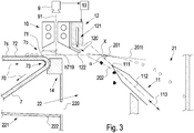
- the Fig. 3 shows a section of an exemplary optical sorting system in the area of the discharge end 7b of the conveyor belt 7.
- a lighting device 10 and a sensor device 9 are arranged in the area of the discharge end 7b above the first free trajectory 201 of the granulate particles 100, and a discharge device 12 is arranged along the flight direction of the granulate particles 100 on the free trajectory 201 following the lighting device 10.
- the optical sensor device 9 is arranged in such a way that it generates the optical recordings of the granulate particles 100 dropped by the conveyor belt 7 at the drop line 71 and transmits them to the control device 13.
- the control device 13 is designed in such a way that it is based on the optical recordings of the sensor device 9 and the evaluation of at least one detection criterion assigns the dropped granulate particles 100 to the at least one first or second granulate fraction and transmits a control pulse to the discharge device 12 when a granulate particle 100 is assigned to the second granulate fraction.
- a control pulse is present, the discharge device 12 pushes an air stream 120 via an air nozzle 121, as a result of which the granulate particles 100 assigned to the second granulate fraction is deflected from the first free trajectory 201 onto a second trajectory 202.
- the air flow 120 of the individual nozzle 121 is directed in a specific direction by means of at least one deflection device 122, such as a deflector plate, for example.
- the first granulate fraction outlet 21 is arranged in the area of the free trajectory 201 of the granulate particles 100 at a defined distance from the discharge end 7b and, when a control pulse is transmitted, the discharge device 12 moves the granulate particles 100 assigned to the at least one second granulate fraction into at least one second trajectory before reaching the first granulate fraction outlet 202 and discharged into at least one second granulate fraction outlet 22.
- the optical sensor device 9 generates recordings of the dropped granulate particles 100 in the area of their free flight path 201.
- the course of an exemplary free flight path 201 is shown in FIG Fig.
- the lighting device 10 is arranged above the free trajectory 201 of the granulate particles 100, and can alternatively also be arranged below the free trajectory 201.
- the illustrated exemplary lighting device 10 has a plurality of light sources, in particular a light-emitting diode. In particular, it can be provided that the lighting intensity and the lighting spectrum of the lighting device are actively controlled and adapted to the granulate particles 100 to be sorted. As in Fig.
- the lighting device 10 is in the direction of the lighting device 10
- a lighting background 14 is arranged opposite the emitted light beams relative to the free trajectory 201 of the particles 100. It can also be provided that the lighting background 14 is actively illuminated, with the lighting intensity and the lighting color also being able to be actively changed.
- the first fraction outlet 21 and the second fraction outlet 22 are separated from one another in their upper area by a separating blade 11.
- the separating sword 11 is arranged behind the discharge end 7b in the discharge direction of the granulate particles 100 between the first free trajectory 201 and the at least one second trajectory 202, the separating sword 11 having a tapered end face 111 in the form of a knife edge, directed relative to the discharge end 7b includes.
- the longitudinal axis 112 of the separating sword 11 is arranged relative to the tangent 201t to the first idealized trajectory 201 of the granulate particles at the intersection x between the longitudinal axis 112 of the separating sword 11 and the first trajectory 201 such that the longitudinal axis 112 has a Includes angle ⁇ in the range of 40-60 ° or preferably 45 °.
- the separating sword 11 can be designed to be linearly displaceable along its longitudinal axis 112, as shown by means of double arrow 113 in FIG Fig. 3 shown.
Landscapes
- Sorting Of Articles (AREA)
Applications Claiming Priority (1)
| Application Number | Priority Date | Filing Date | Title |
|---|---|---|---|
| DE102020110976.8A DE102020110976B4 (de) | 2020-04-22 | 2020-04-22 | Optische Sortieranlage für die Sortierung von Granulatpartikeln |
Publications (3)
| Publication Number | Publication Date |
|---|---|
| EP3900849A2 true EP3900849A2 (fr) | 2021-10-27 |
| EP3900849A3 EP3900849A3 (fr) | 2021-12-29 |
| EP3900849B1 EP3900849B1 (fr) | 2024-02-07 |
Family
ID=75441810
Family Applications (1)
| Application Number | Title | Priority Date | Filing Date |
|---|---|---|---|
| EP21167660.6A Active EP3900849B1 (fr) | 2020-04-22 | 2021-04-09 | Système de tri optique destiné au tri des particules granulaires |
Country Status (2)
| Country | Link |
|---|---|
| EP (1) | EP3900849B1 (fr) |
| DE (1) | DE102020110976B4 (fr) |
Cited By (2)
| Publication number | Priority date | Publication date | Assignee | Title |
|---|---|---|---|---|
| CN118751543A (zh) * | 2024-06-26 | 2024-10-11 | 中国科学院长春光学精密机械与物理研究所 | 一种用于种子分选设备的分体式上料器 |
| CN119588638A (zh) * | 2025-02-10 | 2025-03-11 | 天津美腾科技股份有限公司 | 一种离析布料智能干选机 |
Family Cites Families (11)
| Publication number | Priority date | Publication date | Assignee | Title |
|---|---|---|---|---|
| GB455628A (en) | 1935-04-23 | 1936-10-23 | Edward Joseph Winkleman | Vibratory screen and method of screening |
| US3939983A (en) | 1972-03-16 | 1976-02-24 | Asfour Emil S | Apparatus for sorting tobacco leaves |
| JP3275280B2 (ja) * | 1994-10-07 | 2002-04-15 | 株式会社サタケ | 粒状物色彩選別機における原料供給装置 |
| US6003681A (en) | 1996-06-03 | 1999-12-21 | Src Vision, Inc. | Off-belt stabilizing system for light-weight articles |
| AU1310901A (en) | 1999-10-18 | 2001-04-30 | Stork Screens B.V. | Endless belt made from fibre-reinforced plastics material |
| CA2497882A1 (fr) | 2002-09-17 | 2004-04-01 | Habasit Ag | Bande transporteuse qui peut etre soudee bout a bout |
| DE102009007481A1 (de) | 2009-01-30 | 2010-09-02 | Fraunhofer-Gesellschaft zur Förderung der angewandten Forschung e.V. | Fördersystem zum Transport von Materialien, insbesondere von Schüttgut |
| CN102310998A (zh) | 2011-09-24 | 2012-01-11 | 合肥美亚光电技术股份有限公司 | 一种用于履带式色选机的物料输送装置 |
| WO2016096802A1 (fr) * | 2014-12-15 | 2016-06-23 | Hochschule Rapperswil | Procédé et dispositif pour appareil de triage de matière en vrac |
| DE102016210482A1 (de) | 2016-06-14 | 2017-12-14 | Fraunhofer-Gesellschaft zur Förderung der angewandten Forschung e.V. | Optisches Sortiersystem sowie entsprechendes Sortierverfahren |
| AT520710B1 (de) * | 2017-11-24 | 2022-07-15 | Ife Aufbereitungstechnik Gmbh | Magnetscheider |
-
2020
- 2020-04-22 DE DE102020110976.8A patent/DE102020110976B4/de not_active Expired - Fee Related
-
2021
- 2021-04-09 EP EP21167660.6A patent/EP3900849B1/fr active Active
Cited By (2)
| Publication number | Priority date | Publication date | Assignee | Title |
|---|---|---|---|---|
| CN118751543A (zh) * | 2024-06-26 | 2024-10-11 | 中国科学院长春光学精密机械与物理研究所 | 一种用于种子分选设备的分体式上料器 |
| CN119588638A (zh) * | 2025-02-10 | 2025-03-11 | 天津美腾科技股份有限公司 | 一种离析布料智能干选机 |
Also Published As
| Publication number | Publication date |
|---|---|
| DE102020110976B4 (de) | 2023-12-21 |
| EP3900849A3 (fr) | 2021-12-29 |
| DE102020110976A1 (de) | 2021-10-28 |
| EP3900849B1 (fr) | 2024-02-07 |
Similar Documents
| Publication | Publication Date | Title |
|---|---|---|
| EP3967413B1 (fr) | Appareil et procédé de tri doté d'un dispositif laser libs | |
| EP0982081B1 (fr) | Classification pneumatique de polysilicium | |
| EP0983804A1 (fr) | Dispositif de classification | |
| AT398915B (de) | Verfahren zum auftrennen eines gemisches aus festen teilchen in einzelne fraktionen, sowie anlage zur durchführung des verfahrens | |
| EP0876851A1 (fr) | Dispositif de classement optoélectronique | |
| EP3900849B1 (fr) | Système de tri optique destiné au tri des particules granulaires | |
| DE102016003766A1 (de) | Vereinzelungsvorrichtung | |
| EP2366461B1 (fr) | Séparateur pneumatique doté de plateaux de distribution | |
| EP1930090B1 (fr) | Procédé et dispositif d'élimination de corps étrangers | |
| EP0022945A1 (fr) | Procédé et appareil pour la séparation de matières hétérogènes dans un courant horizontal | |
| EP3677349B1 (fr) | Procédé et dispositif de séparation des pièces longues | |
| DE10196605B3 (de) | Vorrichtung zum Sortieren von Holzschnitzel in separate Fraktionen | |
| DE112016000194B4 (de) | Windkanalumlauf-Sichtvorrichtung für Schüttmaterial | |
| DE69926113T2 (de) | Vorrichtung und verfahren zur sortierung von körnchen | |
| DE20320957U1 (de) | Vorrichtung zum Sortieren von Schüttgütern mit zweistufiger Vereinzelungseinrichtung | |
| EP2800619B1 (fr) | Séparateur du type cyclone, en particulier pour la gestion des déchets | |
| AT412148B (de) | Vorrichtung zum sortieren von holzspänen in getrennte teilmengen | |
| DE102014011401B3 (de) | "Ausblasvorrichtung zum selektiven Ausblasen von Fördergutteilen aus einem Fördergutstrom" | |
| DE202011109982U1 (de) | Verteilvorrichtung mit Verteilertellern | |
| DE2642884A1 (de) | Verfahren zum dispergieren und pneumatischen zufuehren feinkoernigen gutes in die sichtzone eines windsichters | |
| EP4324572B1 (fr) | Système d'analyse et de tri d'une partie de matériau | |
| DE102012010030A1 (de) | Verfahren und vorrichtung zur trennung eines heterogenen materialstroms in mindestens zwei materialfraktionen | |
| EP4572897A1 (fr) | Système d?analyse et de tri d?une pièce de matériau | |
| EP4286063A1 (fr) | Dispositif de tri | |
| EP3571146B1 (fr) | Procédé de tri pour corps creux et dispositif de tri |
Legal Events
| Date | Code | Title | Description |
|---|---|---|---|
| PUAI | Public reference made under article 153(3) epc to a published international application that has entered the european phase |
Free format text: ORIGINAL CODE: 0009012 |
|
| STAA | Information on the status of an ep patent application or granted ep patent |
Free format text: STATUS: THE APPLICATION HAS BEEN PUBLISHED |
|
| AK | Designated contracting states |
Kind code of ref document: A2 Designated state(s): AL AT BE BG CH CY CZ DE DK EE ES FI FR GB GR HR HU IE IS IT LI LT LU LV MC MK MT NL NO PL PT RO RS SE SI SK SM TR |
|
| PUAL | Search report despatched |
Free format text: ORIGINAL CODE: 0009013 |
|
| AK | Designated contracting states |
Kind code of ref document: A3 Designated state(s): AL AT BE BG CH CY CZ DE DK EE ES FI FR GB GR HR HU IE IS IT LI LT LU LV MC MK MT NL NO PL PT RO RS SE SI SK SM TR |
|
| RIC1 | Information provided on ipc code assigned before grant |
Ipc: B07C 5/02 20060101ALI20211122BHEP Ipc: B07C 5/342 20060101AFI20211122BHEP |
|
| STAA | Information on the status of an ep patent application or granted ep patent |
Free format text: STATUS: REQUEST FOR EXAMINATION WAS MADE |
|
| 17P | Request for examination filed |
Effective date: 20220308 |
|
| RBV | Designated contracting states (corrected) |
Designated state(s): AL AT BE BG CH CY CZ DE DK EE ES FI FR GB GR HR HU IE IS IT LI LT LU LV MC MK MT NL NO PL PT RO RS SE SI SK SM TR |
|
| GRAP | Despatch of communication of intention to grant a patent |
Free format text: ORIGINAL CODE: EPIDOSNIGR1 |
|
| STAA | Information on the status of an ep patent application or granted ep patent |
Free format text: STATUS: GRANT OF PATENT IS INTENDED |
|
| INTG | Intention to grant announced |
Effective date: 20230817 |
|
| GRAS | Grant fee paid |
Free format text: ORIGINAL CODE: EPIDOSNIGR3 |
|
| GRAA | (expected) grant |
Free format text: ORIGINAL CODE: 0009210 |
|
| STAA | Information on the status of an ep patent application or granted ep patent |
Free format text: STATUS: THE PATENT HAS BEEN GRANTED |
|
| P01 | Opt-out of the competence of the unified patent court (upc) registered |
Effective date: 20231227 |
|
| AK | Designated contracting states |
Kind code of ref document: B1 Designated state(s): AL AT BE BG CH CY CZ DE DK EE ES FI FR GB GR HR HU IE IS IT LI LT LU LV MC MK MT NL NO PL PT RO RS SE SI SK SM TR |
|
| REG | Reference to a national code |
Ref country code: GB Ref legal event code: FG4D Free format text: NOT ENGLISH |
|
| REG | Reference to a national code |
Ref country code: CH Ref legal event code: EP |
|
| REG | Reference to a national code |
Ref country code: DE Ref legal event code: R096 Ref document number: 502021002624 Country of ref document: DE |
|
| REG | Reference to a national code |
Ref country code: IE Ref legal event code: FG4D Free format text: LANGUAGE OF EP DOCUMENT: GERMAN |
|
| REG | Reference to a national code |
Ref country code: LT Ref legal event code: MG9D |
|
| REG | Reference to a national code |
Ref country code: NL Ref legal event code: MP Effective date: 20240207 |
|
| PG25 | Lapsed in a contracting state [announced via postgrant information from national office to epo] |
Ref country code: IS Free format text: LAPSE BECAUSE OF FAILURE TO SUBMIT A TRANSLATION OF THE DESCRIPTION OR TO PAY THE FEE WITHIN THE PRESCRIBED TIME-LIMIT Effective date: 20240607 |
|
| PG25 | Lapsed in a contracting state [announced via postgrant information from national office to epo] |
Ref country code: LT Free format text: LAPSE BECAUSE OF FAILURE TO SUBMIT A TRANSLATION OF THE DESCRIPTION OR TO PAY THE FEE WITHIN THE PRESCRIBED TIME-LIMIT Effective date: 20240207 |
|
| PG25 | Lapsed in a contracting state [announced via postgrant information from national office to epo] |
Ref country code: GR Free format text: LAPSE BECAUSE OF FAILURE TO SUBMIT A TRANSLATION OF THE DESCRIPTION OR TO PAY THE FEE WITHIN THE PRESCRIBED TIME-LIMIT Effective date: 20240508 |
|
| PG25 | Lapsed in a contracting state [announced via postgrant information from national office to epo] |
Ref country code: HR Free format text: LAPSE BECAUSE OF FAILURE TO SUBMIT A TRANSLATION OF THE DESCRIPTION OR TO PAY THE FEE WITHIN THE PRESCRIBED TIME-LIMIT Effective date: 20240207 Ref country code: NL Free format text: LAPSE BECAUSE OF FAILURE TO SUBMIT A TRANSLATION OF THE DESCRIPTION OR TO PAY THE FEE WITHIN THE PRESCRIBED TIME-LIMIT Effective date: 20240207 |
|
| PG25 | Lapsed in a contracting state [announced via postgrant information from national office to epo] |
Ref country code: ES Free format text: LAPSE BECAUSE OF FAILURE TO SUBMIT A TRANSLATION OF THE DESCRIPTION OR TO PAY THE FEE WITHIN THE PRESCRIBED TIME-LIMIT Effective date: 20240207 |
|
| PG25 | Lapsed in a contracting state [announced via postgrant information from national office to epo] |
Ref country code: NO Free format text: LAPSE BECAUSE OF FAILURE TO SUBMIT A TRANSLATION OF THE DESCRIPTION OR TO PAY THE FEE WITHIN THE PRESCRIBED TIME-LIMIT Effective date: 20240507 Ref country code: NL Free format text: LAPSE BECAUSE OF FAILURE TO SUBMIT A TRANSLATION OF THE DESCRIPTION OR TO PAY THE FEE WITHIN THE PRESCRIBED TIME-LIMIT Effective date: 20240207 Ref country code: LT Free format text: LAPSE BECAUSE OF FAILURE TO SUBMIT A TRANSLATION OF THE DESCRIPTION OR TO PAY THE FEE WITHIN THE PRESCRIBED TIME-LIMIT Effective date: 20240207 Ref country code: IS Free format text: LAPSE BECAUSE OF FAILURE TO SUBMIT A TRANSLATION OF THE DESCRIPTION OR TO PAY THE FEE WITHIN THE PRESCRIBED TIME-LIMIT Effective date: 20240607 Ref country code: HR Free format text: LAPSE BECAUSE OF FAILURE TO SUBMIT A TRANSLATION OF THE DESCRIPTION OR TO PAY THE FEE WITHIN THE PRESCRIBED TIME-LIMIT Effective date: 20240207 Ref country code: GR Free format text: LAPSE BECAUSE OF FAILURE TO SUBMIT A TRANSLATION OF THE DESCRIPTION OR TO PAY THE FEE WITHIN THE PRESCRIBED TIME-LIMIT Effective date: 20240508 Ref country code: FI Free format text: LAPSE BECAUSE OF FAILURE TO SUBMIT A TRANSLATION OF THE DESCRIPTION OR TO PAY THE FEE WITHIN THE PRESCRIBED TIME-LIMIT Effective date: 20240207 Ref country code: ES Free format text: LAPSE BECAUSE OF FAILURE TO SUBMIT A TRANSLATION OF THE DESCRIPTION OR TO PAY THE FEE WITHIN THE PRESCRIBED TIME-LIMIT Effective date: 20240207 Ref country code: BG Free format text: LAPSE BECAUSE OF FAILURE TO SUBMIT A TRANSLATION OF THE DESCRIPTION OR TO PAY THE FEE WITHIN THE PRESCRIBED TIME-LIMIT Effective date: 20240207 |
|
| PG25 | Lapsed in a contracting state [announced via postgrant information from national office to epo] |
Ref country code: PT Free format text: LAPSE BECAUSE OF FAILURE TO SUBMIT A TRANSLATION OF THE DESCRIPTION OR TO PAY THE FEE WITHIN THE PRESCRIBED TIME-LIMIT Effective date: 20240607 Ref country code: PL Free format text: LAPSE BECAUSE OF FAILURE TO SUBMIT A TRANSLATION OF THE DESCRIPTION OR TO PAY THE FEE WITHIN THE PRESCRIBED TIME-LIMIT Effective date: 20240207 |
|
| PG25 | Lapsed in a contracting state [announced via postgrant information from national office to epo] |
Ref country code: SE Free format text: LAPSE BECAUSE OF FAILURE TO SUBMIT A TRANSLATION OF THE DESCRIPTION OR TO PAY THE FEE WITHIN THE PRESCRIBED TIME-LIMIT Effective date: 20240207 Ref country code: PT Free format text: LAPSE BECAUSE OF FAILURE TO SUBMIT A TRANSLATION OF THE DESCRIPTION OR TO PAY THE FEE WITHIN THE PRESCRIBED TIME-LIMIT Effective date: 20240607 Ref country code: PL Free format text: LAPSE BECAUSE OF FAILURE TO SUBMIT A TRANSLATION OF THE DESCRIPTION OR TO PAY THE FEE WITHIN THE PRESCRIBED TIME-LIMIT Effective date: 20240207 Ref country code: LV Free format text: LAPSE BECAUSE OF FAILURE TO SUBMIT A TRANSLATION OF THE DESCRIPTION OR TO PAY THE FEE WITHIN THE PRESCRIBED TIME-LIMIT Effective date: 20240207 |
|
| PG25 | Lapsed in a contracting state [announced via postgrant information from national office to epo] |
Ref country code: DK Free format text: LAPSE BECAUSE OF FAILURE TO SUBMIT A TRANSLATION OF THE DESCRIPTION OR TO PAY THE FEE WITHIN THE PRESCRIBED TIME-LIMIT Effective date: 20240207 |
|
| PG25 | Lapsed in a contracting state [announced via postgrant information from national office to epo] |
Ref country code: SM Free format text: LAPSE BECAUSE OF FAILURE TO SUBMIT A TRANSLATION OF THE DESCRIPTION OR TO PAY THE FEE WITHIN THE PRESCRIBED TIME-LIMIT Effective date: 20240207 |
|
| PG25 | Lapsed in a contracting state [announced via postgrant information from national office to epo] |
Ref country code: CZ Free format text: LAPSE BECAUSE OF FAILURE TO SUBMIT A TRANSLATION OF THE DESCRIPTION OR TO PAY THE FEE WITHIN THE PRESCRIBED TIME-LIMIT Effective date: 20240207 Ref country code: EE Free format text: LAPSE BECAUSE OF FAILURE TO SUBMIT A TRANSLATION OF THE DESCRIPTION OR TO PAY THE FEE WITHIN THE PRESCRIBED TIME-LIMIT Effective date: 20240207 |
|
| PG25 | Lapsed in a contracting state [announced via postgrant information from national office to epo] |
Ref country code: SK Free format text: LAPSE BECAUSE OF FAILURE TO SUBMIT A TRANSLATION OF THE DESCRIPTION OR TO PAY THE FEE WITHIN THE PRESCRIBED TIME-LIMIT Effective date: 20240207 |
|
| PG25 | Lapsed in a contracting state [announced via postgrant information from national office to epo] |
Ref country code: SM Free format text: LAPSE BECAUSE OF FAILURE TO SUBMIT A TRANSLATION OF THE DESCRIPTION OR TO PAY THE FEE WITHIN THE PRESCRIBED TIME-LIMIT Effective date: 20240207 Ref country code: SK Free format text: LAPSE BECAUSE OF FAILURE TO SUBMIT A TRANSLATION OF THE DESCRIPTION OR TO PAY THE FEE WITHIN THE PRESCRIBED TIME-LIMIT Effective date: 20240207 Ref country code: RO Free format text: LAPSE BECAUSE OF FAILURE TO SUBMIT A TRANSLATION OF THE DESCRIPTION OR TO PAY THE FEE WITHIN THE PRESCRIBED TIME-LIMIT Effective date: 20240207 Ref country code: EE Free format text: LAPSE BECAUSE OF FAILURE TO SUBMIT A TRANSLATION OF THE DESCRIPTION OR TO PAY THE FEE WITHIN THE PRESCRIBED TIME-LIMIT Effective date: 20240207 Ref country code: DK Free format text: LAPSE BECAUSE OF FAILURE TO SUBMIT A TRANSLATION OF THE DESCRIPTION OR TO PAY THE FEE WITHIN THE PRESCRIBED TIME-LIMIT Effective date: 20240207 Ref country code: CZ Free format text: LAPSE BECAUSE OF FAILURE TO SUBMIT A TRANSLATION OF THE DESCRIPTION OR TO PAY THE FEE WITHIN THE PRESCRIBED TIME-LIMIT Effective date: 20240207 |
|
| REG | Reference to a national code |
Ref country code: DE Ref legal event code: R097 Ref document number: 502021002624 Country of ref document: DE |
|
| PG25 | Lapsed in a contracting state [announced via postgrant information from national office to epo] |
Ref country code: MC Free format text: LAPSE BECAUSE OF FAILURE TO SUBMIT A TRANSLATION OF THE DESCRIPTION OR TO PAY THE FEE WITHIN THE PRESCRIBED TIME-LIMIT Effective date: 20240207 |
|
| PG25 | Lapsed in a contracting state [announced via postgrant information from national office to epo] |
Ref country code: MC Free format text: LAPSE BECAUSE OF FAILURE TO SUBMIT A TRANSLATION OF THE DESCRIPTION OR TO PAY THE FEE WITHIN THE PRESCRIBED TIME-LIMIT Effective date: 20240207 |
|
| REG | Reference to a national code |
Ref country code: CH Ref legal event code: PL |
|
| PG25 | Lapsed in a contracting state [announced via postgrant information from national office to epo] |
Ref country code: IT Free format text: LAPSE BECAUSE OF FAILURE TO SUBMIT A TRANSLATION OF THE DESCRIPTION OR TO PAY THE FEE WITHIN THE PRESCRIBED TIME-LIMIT Effective date: 20240207 |
|
| PLBE | No opposition filed within time limit |
Free format text: ORIGINAL CODE: 0009261 |
|
| STAA | Information on the status of an ep patent application or granted ep patent |
Free format text: STATUS: NO OPPOSITION FILED WITHIN TIME LIMIT |
|
| PG25 | Lapsed in a contracting state [announced via postgrant information from national office to epo] |
Ref country code: LU Free format text: LAPSE BECAUSE OF NON-PAYMENT OF DUE FEES Effective date: 20240409 |
|
| PG25 | Lapsed in a contracting state [announced via postgrant information from national office to epo] |
Ref country code: LU Free format text: LAPSE BECAUSE OF NON-PAYMENT OF DUE FEES Effective date: 20240409 Ref country code: IT Free format text: LAPSE BECAUSE OF FAILURE TO SUBMIT A TRANSLATION OF THE DESCRIPTION OR TO PAY THE FEE WITHIN THE PRESCRIBED TIME-LIMIT Effective date: 20240207 |
|
| 26N | No opposition filed |
Effective date: 20241108 |
|
| PG25 | Lapsed in a contracting state [announced via postgrant information from national office to epo] |
Ref country code: CH Free format text: LAPSE BECAUSE OF NON-PAYMENT OF DUE FEES Effective date: 20240430 |
|
| PG25 | Lapsed in a contracting state [announced via postgrant information from national office to epo] |
Ref country code: IE Free format text: LAPSE BECAUSE OF NON-PAYMENT OF DUE FEES Effective date: 20240409 |
|
| PG25 | Lapsed in a contracting state [announced via postgrant information from national office to epo] |
Ref country code: SI Free format text: LAPSE BECAUSE OF FAILURE TO SUBMIT A TRANSLATION OF THE DESCRIPTION OR TO PAY THE FEE WITHIN THE PRESCRIBED TIME-LIMIT Effective date: 20240207 |
|
| PG25 | Lapsed in a contracting state [announced via postgrant information from national office to epo] |
Ref country code: RS Free format text: LAPSE BECAUSE OF FAILURE TO SUBMIT A TRANSLATION OF THE DESCRIPTION OR TO PAY THE FEE WITHIN THE PRESCRIBED TIME-LIMIT Effective date: 20240207 |
|
| PGFP | Annual fee paid to national office [announced via postgrant information from national office to epo] |
Ref country code: DE Payment date: 20250314 Year of fee payment: 5 |
|
| PGFP | Annual fee paid to national office [announced via postgrant information from national office to epo] |
Ref country code: BE Payment date: 20250422 Year of fee payment: 5 |
|
| PGFP | Annual fee paid to national office [announced via postgrant information from national office to epo] |
Ref country code: FR Payment date: 20250422 Year of fee payment: 5 |
|
| PGFP | Annual fee paid to national office [announced via postgrant information from national office to epo] |
Ref country code: AT Payment date: 20250721 Year of fee payment: 5 |
|
| PG25 | Lapsed in a contracting state [announced via postgrant information from national office to epo] |
Ref country code: CY Free format text: LAPSE BECAUSE OF FAILURE TO SUBMIT A TRANSLATION OF THE DESCRIPTION OR TO PAY THE FEE WITHIN THE PRESCRIBED TIME-LIMIT; INVALID AB INITIO Effective date: 20210409 |
|
| PG25 | Lapsed in a contracting state [announced via postgrant information from national office to epo] |
Ref country code: HU Free format text: LAPSE BECAUSE OF FAILURE TO SUBMIT A TRANSLATION OF THE DESCRIPTION OR TO PAY THE FEE WITHIN THE PRESCRIBED TIME-LIMIT; INVALID AB INITIO Effective date: 20210409 |
|
| PGFP | Annual fee paid to national office [announced via postgrant information from national office to epo] |
Ref country code: GB Payment date: 20260324 Year of fee payment: 6 |