EP3900855A1 - Drehbarer einsatz und tauchdüse - Google Patents
Drehbarer einsatz und tauchdüse Download PDFInfo
- Publication number
- EP3900855A1 EP3900855A1 EP20170500.1A EP20170500A EP3900855A1 EP 3900855 A1 EP3900855 A1 EP 3900855A1 EP 20170500 A EP20170500 A EP 20170500A EP 3900855 A1 EP3900855 A1 EP 3900855A1
- Authority
- EP
- European Patent Office
- Prior art keywords
- rotatable insert
- nozzle
- submerged
- insert
- passageway
- Prior art date
- Legal status (The legal status is an assumption and is not a legal conclusion. Google has not performed a legal analysis and makes no representation as to the accuracy of the status listed.)
- Withdrawn
Links
- 229910000831 Steel Inorganic materials 0.000 claims abstract description 24
- 239000010959 steel Substances 0.000 claims abstract description 24
- 239000002184 metal Substances 0.000 claims description 13
- 239000011819 refractory material Substances 0.000 claims description 9
- 239000012530 fluid Substances 0.000 claims description 8
- 238000000034 method Methods 0.000 claims description 7
- 238000009749 continuous casting Methods 0.000 claims description 6
- 229910052582 BN Inorganic materials 0.000 claims description 4
- PZNSFCLAULLKQX-UHFFFAOYSA-N Boron nitride Chemical compound N#B PZNSFCLAULLKQX-UHFFFAOYSA-N 0.000 claims description 4
- 230000005499 meniscus Effects 0.000 description 12
- 238000005096 rolling process Methods 0.000 description 6
- 238000005266 casting Methods 0.000 description 5
- XLYOFNOQVPJJNP-UHFFFAOYSA-N water Substances O XLYOFNOQVPJJNP-UHFFFAOYSA-N 0.000 description 2
- OKTJSMMVPCPJKN-UHFFFAOYSA-N Carbon Chemical group [C] OKTJSMMVPCPJKN-UHFFFAOYSA-N 0.000 description 1
- 229910052799 carbon Inorganic materials 0.000 description 1
- 230000000052 comparative effect Effects 0.000 description 1
- 239000007788 liquid Substances 0.000 description 1
- 238000004519 manufacturing process Methods 0.000 description 1
- 239000000203 mixture Substances 0.000 description 1
- 239000002893 slag Substances 0.000 description 1
Images

Classifications
-
- B—PERFORMING OPERATIONS; TRANSPORTING
- B22—CASTING; POWDER METALLURGY
- B22D—CASTING OF METALS; CASTING OF OTHER SUBSTANCES BY THE SAME PROCESSES OR DEVICES
- B22D41/00—Casting melt-holding vessels, e.g. ladles, tundishes, cups or the like
- B22D41/50—Pouring-nozzles
- B22D41/507—Pouring-nozzles giving a rotating motion to the issuing molten metal
-
- B—PERFORMING OPERATIONS; TRANSPORTING
- B22—CASTING; POWDER METALLURGY
- B22D—CASTING OF METALS; CASTING OF OTHER SUBSTANCES BY THE SAME PROCESSES OR DEVICES
- B22D11/00—Continuous casting of metals, i.e. casting in indefinite lengths
- B22D11/06—Continuous casting of metals, i.e. casting in indefinite lengths into moulds with travelling walls, e.g. with rolls, plates, belts, caterpillars
- B22D11/0637—Accessories therefor
- B22D11/064—Accessories therefor for supplying molten metal
- B22D11/0642—Nozzles
-
- B—PERFORMING OPERATIONS; TRANSPORTING
- B22—CASTING; POWDER METALLURGY
- B22D—CASTING OF METALS; CASTING OF OTHER SUBSTANCES BY THE SAME PROCESSES OR DEVICES
- B22D11/00—Continuous casting of metals, i.e. casting in indefinite lengths
- B22D11/10—Supplying or treating molten metal
- B22D11/103—Distributing the molten metal, e.g. using runners, floats, distributors
-
- B—PERFORMING OPERATIONS; TRANSPORTING
- B22—CASTING; POWDER METALLURGY
- B22D—CASTING OF METALS; CASTING OF OTHER SUBSTANCES BY THE SAME PROCESSES OR DEVICES
- B22D41/00—Casting melt-holding vessels, e.g. ladles, tundishes, cups or the like
- B22D41/50—Pouring-nozzles
- B22D41/52—Manufacturing or repairing thereof
-
- B—PERFORMING OPERATIONS; TRANSPORTING
- B22—CASTING; POWDER METALLURGY
- B22D—CASTING OF METALS; CASTING OF OTHER SUBSTANCES BY THE SAME PROCESSES OR DEVICES
- B22D41/00—Casting melt-holding vessels, e.g. ladles, tundishes, cups or the like
- B22D41/50—Pouring-nozzles
- B22D41/62—Pouring-nozzles with stirring or vibrating means
Definitions
- the invention relates to a rotatable insert for a submerged nozzle and a submerged nozzle, in particular a submerged entry nozzle (SEN), a monotube (MT), or a submerged entry shroud (SES), through which molten steel can be poured from a tundish into a mould, and to a method for continuous casting of molten steel, using the submerged nozzle.
- a submerged entry nozzle SEN
- MT monotube
- SES submerged entry shroud
- Submerged nozzles such as submerged entry nozzles (SEN) a monotubes, or submerged entry shrouds (SES) are known, for example from EP 1 671 721 B1 or EP 3 488 949 A1 or EP 2 382 062 B1 .
- Such nozzles generally comprise a substantially tubular body extending from a first end to a second end, with a passageway (for example a bore), extending through the tubular body along a longitudinal axis from the first to the second end. In its use position in the continuous casting machine, the nozzle is arranged generally vertically, with the central longitudinal axis of the passageway extending vertically and with the first end of the tubular body positioned upside and the second end of the tubular body positioned downside.
- SEN submerged entry nozzles
- SES submerged entry shrouds
- At least one inlet port at the first end is present, where molten metal can enter into the passageway, the inlet port opens into the passageway.
- a plurality of outlet ports is present, where molten metal can exit the passageway (and leave the submerged nozzle into a mould), the outlet ports open into the passageway in a region adjacent to the second end.
- the nozzle is arranged generally vertical, with the first end above the second end.
- a rotatable insert for use in a submerged nozzle through which molten steel can be poured from a tundish into a mould according to claim 1, a submerged nozzle through which molten steel can be poured from a tundish into a mould according to claim 9, and a method for continuous casting of molten steel according to claim 15.
- the advantages and refinements mentioned in connection with the method also apply analogously to the products / physical objects and vice versa.
- the core idea of the invention is based on the finding, that by having a rotatable insert it was found that the flow stability is improved, and that during casting, the undesired meniscus roll can be strongly reduced or even completely prevented.
- the object is achieved by providing a rotatable insert for use in a submerged nozzle through which molten steel can be poured from a tundish into a mould.
- the at least one rotatable insert comprises blades.
- the blades can drive the rotation of the insert, when a fluid flows through the passageway.
- the at least one rotatable insert defines an axis of rotation and comprises blades with an angle between at least one surface normal of the blades and the axis of rotation in the range of 10° to 85°, more preferably in the range of 20° to 80°.
- an insert will rotate around the axis of rotation, due to the force of a streaming fluid.
- the angle between the at least one surface normal of the blades and the axis of rotation is to be understood as the smaller angle (that is ⁇ 90°) between a first line (or direction) defined by at least one surface normal of the blades (that is the normal direction to the surface of the blade) with respect to a second line (or direction) defined by the axis of rotation.
- the at least one rotatable insert comprises 2 to 15 blades. More preferably, the at least one rotatable insert comprises 3 to 15 blades.
- the at least one rotatable insert comprises a shaft.
- the at least one rotatable insert can be in the form of a propeller.
- the at least one rotatable insert is in the form of a propeller with a minimum of 3 blades.
- the at least one rotatable insert is in the form of a propeller with a maximum of 15 blades.
- the propeller may comprise a shaft.
- the propeller may be a shaft-less propeller.
- the at least one rotatable insert is in the form of a propeller having a propeller pitch of at least 50 mm, preferably 100 mm, more preferably 200 mm.
- the at least one rotatable insert is in the form of a propeller having a propeller pitch of less than 2000 mm, preferably less than 1500 mm, more preferably less than 1000 mm.
- the at least one rotatable insert may be made from a refractory material.
- the at least one rotatable insert is made from a fine-grained refractory material, such as a refractory material with a maximum grain size of less than 2 mm, preferably less than 1 mm, more preferably less than 0,7 mm. This allows for smooth surfaces of the insert, especially for the blades.
- the at least one rotatable insert is made from boron nitride. This leads to highly stable geometries of the insert.
- the object is achieved by providing a submerged nozzle through which molten steel can be poured from a tundish into a mould, said nozzle comprising:
- the at least one rotatable insert is positioned inside the passageway.
- the at least one rotatable insert is positioned inside the passageway in the region adjacent to said second end.
- the submerged entry nozzle with the at least one rotatable insert may be configured such that a molten metal entering the submerged entry nozzle at the at least one inlet port flows through the passageway and around the rotatable insert and exits the submerged entry nozzle via the plurality of outlet ports, such that a rotation of the rotatable insert is driven by the stream of molten metal.
- the rotatable insert rotates with respect to the substantial tubular body when a fluid (such as molten steel / a metal melt) flows through the passageway.
- a fluid such as molten steel / a metal melt
- the rotatable insert is not connected to the turbular body, such that the rotatable insert can rotate.
- the axis of rotation of the rotatable insert coincides with the longitudinal axis (A) of the tubular body.
- the at least one inlet port of the submerged nozzle consists of one inlet port.
- the height of the rotatable insert is larger than the (largest) height of the plurality of outlet ports.
- the submerged nozzle according to the invention is a submerged entry nozzle (SEN) or a monotube (MT) or a submerged entry shroud (SES).
- SEN submerged entry nozzle
- MT monotube
- SES submerged entry shroud
- the object is achieved by providing a method for continuous casting of molten steel, using a nozzle according to the invention.
- the method allows the production of steel with a high quality, due to the stability of the metal flow resulting in reduced amounts of inclusions.
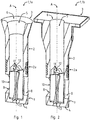
- Fig. 1 shows a cross-section through a submerged nozzle (1), which is a submerged entry nozzle (1a) in its use position.
- the submerged nozzle (1) comprises a substantially tubular body (2) extending from a first end (3) (upper end) to a second end (4) (lower end), the substantially tubular body (2) is made of a carbon bonded refractory material.
- the submerged entry nozzle (1) further comprises a passageway (5), which extends through the tubular body (2), along a longitudinal axis (A) from the first end (3) to the second end (4).
- the passageway (5) defines a rotationally symmetrical opening, here in the form of a circular cylinder, with its axis coinciding with the longitudinal axis (A) of the submerged nozzle (2).
- the inlet port (6) opens into the passageway (5).
- two outlet ports (8) open into the passageway (5).
- the outlet ports (8) are circular openings in the wall of the tubular body (2).
- the submerged entry nozzle (1) further comprises a rotatable insert (10).
- the rotatable insert (10) is positioned inside the passageway (5), in a region (7) adjacent to the second end (4).
- the submerged entry nozzle (1) with the at least one rotatable insert (10) is configured that a molten metal entering the submerged entry nozzle (1) at the at least one inlet port (6) flows through the passageway (5) and around the rotatable insert (10) and exits the submerged entry nozzle (1) via the plurality of outlet ports (8), such that a rotation of the rotatable insert (10) is driven by the stream of molten metal.
- the at least one rotatable insert (10) rotates with respect to the substantial tubular body (2) when a fluid, such as a molten metal, flows through the passageway (5).
- Fig. 2 shows a cross-section through a submerged nozzle (1), which is a monotube (1b) in its use position.
- the difference to the submerged entry nozzle (1a) as shown in Fig. 1 is the geometry of the monotube (1b) at its first end (3).
- the monotube (1b) shows a connection portion for connection to a slide gate plate attachment (not shown).
- the other parts of the monotube (1b) are functionally similar to the respective parts described in connection with the submerged entry nozzle (1a) of Fig. 1 .
- Fig. 3 shows a schematic perspective view of a first rotatable insert (10) embodiment, the at least one rotatable insert (10) defines an axis of rotation (13).
- the at least one rotatable insert (10) is in the form of a propeller with a shaft (12) and with 4 blades (11), the blades (11) featuring a design in that the angle between the respective surface normal (14) of the blade (11) and the axis of rotation (13) is constant over the height of the insert (10).
- the at least one rotatable insert (10) is in the form of a propeller having a propeller pitch of 400 mm, in an alternative setup of 560 mm.
- the at least one rotatable insert (10) is made from a fine-grained refractory material, here the at least one rotatable insert (10) is made from boron nitride, with a maximum grain size of 0,3 mm.
- Fig. 4 shows a schematic perspective view of a second rotatable insert (10) embodiment, the at least one rotatable insert (10) defines an axis of rotation (13).
- the at least one rotatable insert (10) is in the form of a shaft-less propeller with 10 blades (11) (this design can be called Francis Turbine).
- the at least one rotatable insert (10) is in the form of a propeller having a propeller pitch of 450 mm.
- the at least one rotatable insert (10) is made from a fine-grained refractory material, here the at least one rotatable insert (10) is made from boron nitride, with a maximum grain size of 0,3 mm.
- the rotatable insert (10) of Fig. 4 can be used in the embodiments according to Fig. 1 and 2 .
- the mould flow pattern of a submerged nozzle according to the invention was compared to a submerged nozzle with an empty casting channel.
- the following basic flow patterns in the mould here the mould is of rectangular shape
Landscapes
- Engineering & Computer Science (AREA)
- Mechanical Engineering (AREA)
- Manufacturing & Machinery (AREA)
- Continuous Casting (AREA)
- Casting Support Devices, Ladles, And Melt Control Thereby (AREA)
Priority Applications (9)
| Application Number | Priority Date | Filing Date | Title |
|---|---|---|---|
| EP20170500.1A EP3900855A1 (de) | 2020-04-21 | 2020-04-21 | Drehbarer einsatz und tauchdüse |
| US17/918,847 US12017273B2 (en) | 2020-04-21 | 2021-04-21 | Submerged nozzle with rotatable insert |
| CN202180022025.XA CN115315325B (zh) | 2020-04-21 | 2021-04-21 | 具有可旋转插入件的浸入式水口 |
| KR1020227040693A KR20230002935A (ko) | 2020-04-21 | 2021-04-21 | 회전 가능한 인서트를 갖는 침지 노즐 |
| PCT/EP2021/060258 WO2021214070A2 (en) | 2020-04-21 | 2021-04-21 | Submerged nozzle with rotatable insert |
| PL21717990.2T PL4139069T3 (pl) | 2020-04-21 | 2021-04-21 | Wylew kadziowy zanurzony z wkładką obrotową |
| MX2022012803A MX2022012803A (es) | 2020-04-21 | 2021-04-21 | Boquilla sumergida con inserto giratorio. |
| EP21717990.2A EP4139069B1 (de) | 2020-04-21 | 2021-04-21 | Tauchdüse mit drehbarem einsatz |
| BR112022017031A BR112022017031A2 (pt) | 2020-04-21 | 2021-04-21 | Bocal submerso com inserto giratório |
Applications Claiming Priority (1)
| Application Number | Priority Date | Filing Date | Title |
|---|---|---|---|
| EP20170500.1A EP3900855A1 (de) | 2020-04-21 | 2020-04-21 | Drehbarer einsatz und tauchdüse |
Publications (1)
| Publication Number | Publication Date |
|---|---|
| EP3900855A1 true EP3900855A1 (de) | 2021-10-27 |
Family
ID=70390811
Family Applications (2)
| Application Number | Title | Priority Date | Filing Date |
|---|---|---|---|
| EP20170500.1A Withdrawn EP3900855A1 (de) | 2020-04-21 | 2020-04-21 | Drehbarer einsatz und tauchdüse |
| EP21717990.2A Active EP4139069B1 (de) | 2020-04-21 | 2021-04-21 | Tauchdüse mit drehbarem einsatz |
Family Applications After (1)
| Application Number | Title | Priority Date | Filing Date |
|---|---|---|---|
| EP21717990.2A Active EP4139069B1 (de) | 2020-04-21 | 2021-04-21 | Tauchdüse mit drehbarem einsatz |
Country Status (7)
| Country | Link |
|---|---|
| US (1) | US12017273B2 (de) |
| EP (2) | EP3900855A1 (de) |
| KR (1) | KR20230002935A (de) |
| BR (1) | BR112022017031A2 (de) |
| MX (1) | MX2022012803A (de) |
| PL (1) | PL4139069T3 (de) |
| WO (1) | WO2021214070A2 (de) |
Families Citing this family (1)
| Publication number | Priority date | Publication date | Assignee | Title |
|---|---|---|---|---|
| EP3900855A1 (de) | 2020-04-21 | 2021-10-27 | Refractory Intellectual Property GmbH & Co. KG | Drehbarer einsatz und tauchdüse |
Citations (6)
| Publication number | Priority date | Publication date | Assignee | Title |
|---|---|---|---|---|
| EP0030910A1 (de) * | 1979-12-17 | 1981-06-24 | Arbed S.A. | Tauchrohre für elektrorotierendes Stranggiessen von Metallen |
| EP1671721B1 (de) | 2003-08-22 | 2009-07-15 | Krosakiharima Corporation | Tauchdüse für strangguss von stahl und verfahren zum stranggiessen von stahl unter verwendung der tauchdüse |
| WO2015018543A1 (en) * | 2013-08-05 | 2015-02-12 | Refractory Intellectual Property Gmbh & Co. Kg | Refractory ceramic nozzle |
| CN108436071A (zh) * | 2018-05-31 | 2018-08-24 | 东北大学秦皇岛分校 | 一种连铸用自旋流长水口 |
| EP3488949A1 (de) | 2017-11-22 | 2019-05-29 | Refractory Intellectual Property GmbH & Co. KG | Eintauchausguss |
| EP2382062B1 (de) | 2009-01-21 | 2019-08-14 | Refractory Intellectual Property GmbH & Co. KG | Taucheintrittsdüse |
Family Cites Families (4)
| Publication number | Priority date | Publication date | Assignee | Title |
|---|---|---|---|---|
| JPH0474820A (ja) | 1990-07-17 | 1992-03-10 | Sumitomo Metal Ind Ltd | 溶鋼の脱ガス促進方法 |
| WO1999015291A1 (en) * | 1997-09-22 | 1999-04-01 | Katsukiyo Marukawa | Immersion nozzle |
| KR101129841B1 (ko) * | 2009-09-28 | 2012-03-23 | 현대제철 주식회사 | 연속 주조설비용 침지 노즐의 교반장치 |
| EP3900855A1 (de) | 2020-04-21 | 2021-10-27 | Refractory Intellectual Property GmbH & Co. KG | Drehbarer einsatz und tauchdüse |
-
2020
- 2020-04-21 EP EP20170500.1A patent/EP3900855A1/de not_active Withdrawn
-
2021
- 2021-04-21 BR BR112022017031A patent/BR112022017031A2/pt unknown
- 2021-04-21 MX MX2022012803A patent/MX2022012803A/es unknown
- 2021-04-21 WO PCT/EP2021/060258 patent/WO2021214070A2/en not_active Ceased
- 2021-04-21 US US17/918,847 patent/US12017273B2/en active Active
- 2021-04-21 KR KR1020227040693A patent/KR20230002935A/ko active Pending
- 2021-04-21 PL PL21717990.2T patent/PL4139069T3/pl unknown
- 2021-04-21 EP EP21717990.2A patent/EP4139069B1/de active Active
Patent Citations (6)
| Publication number | Priority date | Publication date | Assignee | Title |
|---|---|---|---|---|
| EP0030910A1 (de) * | 1979-12-17 | 1981-06-24 | Arbed S.A. | Tauchrohre für elektrorotierendes Stranggiessen von Metallen |
| EP1671721B1 (de) | 2003-08-22 | 2009-07-15 | Krosakiharima Corporation | Tauchdüse für strangguss von stahl und verfahren zum stranggiessen von stahl unter verwendung der tauchdüse |
| EP2382062B1 (de) | 2009-01-21 | 2019-08-14 | Refractory Intellectual Property GmbH & Co. KG | Taucheintrittsdüse |
| WO2015018543A1 (en) * | 2013-08-05 | 2015-02-12 | Refractory Intellectual Property Gmbh & Co. Kg | Refractory ceramic nozzle |
| EP3488949A1 (de) | 2017-11-22 | 2019-05-29 | Refractory Intellectual Property GmbH & Co. KG | Eintauchausguss |
| CN108436071A (zh) * | 2018-05-31 | 2018-08-24 | 东北大学秦皇岛分校 | 一种连铸用自旋流长水口 |
Also Published As
| Publication number | Publication date |
|---|---|
| PL4139069T3 (pl) | 2024-08-26 |
| EP4139069A2 (de) | 2023-03-01 |
| WO2021214070A2 (en) | 2021-10-28 |
| US12017273B2 (en) | 2024-06-25 |
| MX2022012803A (es) | 2022-11-14 |
| EP4139069C0 (de) | 2024-05-01 |
| EP4139069B1 (de) | 2024-05-01 |
| CN115315325A (zh) | 2022-11-08 |
| BR112022017031A2 (pt) | 2022-12-20 |
| US20230136922A1 (en) | 2023-05-04 |
| WO2021214070A3 (en) | 2022-01-20 |
| KR20230002935A (ko) | 2023-01-05 |
Similar Documents
| Publication | Publication Date | Title |
|---|---|---|
| US5314099A (en) | Casting spout for metallurgical vessels | |
| USRE45093E1 (en) | Submerged entry nozzle with installable parts | |
| US20070241142A1 (en) | Submerged entry nozzle | |
| EP0662021B1 (de) | Feuerfester artikel zur verhinderung der wirbelung in metallurgischen gefässen | |
| EP0925132A1 (de) | Tauchgiessrohr zum stranggiessen von dünnbrammen | |
| RU2203771C2 (ru) | Погружное сопло | |
| US5716538A (en) | Discharge nozzle for continuous casting | |
| CN204892938U (zh) | 用于铸造由金属制成的薄板坯的薄板坯水口及金属铸造设施 | |
| US20060243760A1 (en) | Submerged entry nozzle | |
| US9643248B2 (en) | Impact pad, tundish and apparatus including the impact pad, and method of using same | |
| EP4139069B1 (de) | Tauchdüse mit drehbarem einsatz | |
| GB2066438A (en) | Method and apparatus for separating slag and pouring molten steel out of a container such as a converter or the like | |
| CA2159256A1 (en) | Discharge nozzle for a crystalliser for continuous casting of slabs | |
| EP3743231B1 (de) | Eintauchausguss zum stranggiessen | |
| MXPA06005561A (es) | Boquilla de colado con salidas multiples. | |
| EP4558295B1 (de) | Stopfenstange und verfahren zur erzeugung eines rotationsflusses eines schmolzenen metalls | |
| CA2744385C (en) | Tundish impact pad | |
| US6857465B2 (en) | Method for the production of a continously-cast precursor | |
| CN115315325B (zh) | 具有可旋转插入件的浸入式水口 | |
| US5173198A (en) | Devices used for teeming liquid metals | |
| US6409056B1 (en) | Refractory product | |
| WO1996001709A1 (en) | Dual tundishes for use with twin-roll caster | |
| JP7616520B2 (ja) | 鋼の連続鋳造方法 | |
| EP1759789B1 (de) | Ausgussdüsenstruktur und Verfahren zum steigenden Gießen | |
| RU2310545C1 (ru) | Машина непрерывного литья заготовок |
Legal Events
| Date | Code | Title | Description |
|---|---|---|---|
| PUAI | Public reference made under article 153(3) epc to a published international application that has entered the european phase |
Free format text: ORIGINAL CODE: 0009012 |
|
| STAA | Information on the status of an ep patent application or granted ep patent |
Free format text: STATUS: THE APPLICATION HAS BEEN PUBLISHED |
|
| AK | Designated contracting states |
Kind code of ref document: A1 Designated state(s): AL AT BE BG CH CY CZ DE DK EE ES FI FR GB GR HR HU IE IS IT LI LT LU LV MC MK MT NL NO PL PT RO RS SE SI SK SM TR |
|
| B565 | Issuance of search results under rule 164(2) epc |
Effective date: 20200818 |
|
| STAA | Information on the status of an ep patent application or granted ep patent |
Free format text: STATUS: THE APPLICATION IS DEEMED TO BE WITHDRAWN |
|
| 18D | Application deemed to be withdrawn |
Effective date: 20220429 |