EP3900882A1 - Élément d'appui pour machine-outils - Google Patents
Élément d'appui pour machine-outils Download PDFInfo
- Publication number
- EP3900882A1 EP3900882A1 EP20170492.1A EP20170492A EP3900882A1 EP 3900882 A1 EP3900882 A1 EP 3900882A1 EP 20170492 A EP20170492 A EP 20170492A EP 3900882 A1 EP3900882 A1 EP 3900882A1
- Authority
- EP
- European Patent Office
- Prior art keywords
- locking
- tool
- base body
- locking elements
- machine tool
- Prior art date
- Legal status (The legal status is an assumption and is not a legal conclusion. Google has not performed a legal analysis and makes no representation as to the accuracy of the status listed.)
- Withdrawn
Links
- 239000013013 elastic material Substances 0.000 claims abstract description 6
- 230000005540 biological transmission Effects 0.000 description 4
- 239000000463 material Substances 0.000 description 3
- 229920001971 elastomer Polymers 0.000 description 2
- 230000002441 reversible effect Effects 0.000 description 2
- 239000000758 substrate Substances 0.000 description 2
- 239000000806 elastomer Substances 0.000 description 1
- 230000000630 rising effect Effects 0.000 description 1
Images










Classifications
-
- B—PERFORMING OPERATIONS; TRANSPORTING
- B25—HAND TOOLS; PORTABLE POWER-DRIVEN TOOLS; MANIPULATORS
- B25D—PERCUSSIVE TOOLS
- B25D17/00—Details of, or accessories for, portable power-driven percussive tools
- B25D17/08—Means for retaining and guiding the tool bit, e.g. chucks allowing axial oscillation of the tool bit
- B25D17/084—Rotating chucks or sockets
- B25D17/088—Rotating chucks or sockets with radial movable locking elements co-operating with bit shafts specially adapted therefor
-
- B—PERFORMING OPERATIONS; TRANSPORTING
- B25—HAND TOOLS; PORTABLE POWER-DRIVEN TOOLS; MANIPULATORS
- B25D—PERCUSSIVE TOOLS
- B25D2217/00—Details of, or accessories for, portable power-driven percussive tools
- B25D2217/003—Details relating to chucks with radially movable locking elements
- B25D2217/0038—Locking members of special shape
-
- B—PERFORMING OPERATIONS; TRANSPORTING
- B25—HAND TOOLS; PORTABLE POWER-DRIVEN TOOLS; MANIPULATORS
- B25D—PERCUSSIVE TOOLS
- B25D2250/00—General details of portable percussive tools; Components used in portable percussive tools
- B25D2250/085—Elastic behaviour of tool components
-
- B—PERFORMING OPERATIONS; TRANSPORTING
- B25—HAND TOOLS; PORTABLE POWER-DRIVEN TOOLS; MANIPULATORS
- B25D—PERCUSSIVE TOOLS
- B25D2250/00—General details of portable percussive tools; Components used in portable percussive tools
- B25D2250/231—Sleeve details
- B25D2250/235—Sleeve couplings
Definitions
- the present invention relates to a machine tool, in particular a chisel hammer or combi hammer, containing an impact mechanism for generating impact pulses on a tool with a base body for receiving a rear end of the tool, at least a first and second locking element, each of which is reversible in radial openings in the base body Locking position or release position are arranged horizontally, wherein in the locking position the rear end of the tool is held in the base body and in the release position the rear end of the tool can be removed from the base body, a locking ring for holding the at least first and second locking elements in the locking position and a Pressure element for guiding the at least the at least first and second locking element in a first axial and second axial direction.
- Machine tools in the form of a chisel hammer or combination hammer of the type mentioned are basically known from the prior art.
- Chisel hammers or combination hammers usually have a tool holder for receiving and holding a tool on the machine tool.
- the tool holders transmit the torque that is generated in the machine tool drive to the tools, ensure the transmission of impact pulses from a hammer mechanism to the ground by allowing limited axial movements and prevent the tools from falling out of the machine tools.
- the components of the tool holder are exposed to high dynamic vibrations due to high frequency impact mechanism pulses. If the tools are accelerated by impact impulses from the hammer mechanism, but this impact energy cannot be passed on to a substrate to be removed, this is known as tool blank impacts. These tool strikes can cause considerable damage to the machine tool, since the energy of the impact pulses is not transferred to the substrate to be processed (ie material), but is degraded on the components of the machine tool and in particular on the tool holder.
- a machine tool in particular a chisel hammer or combination hammer, containing an impact mechanism for generating impact pulses on a tool with a base body for receiving a rear end of the tool, at least one first and second locking element, each of which is reversible in radial openings in the base body a locking position or release position, wherein in the locking position the rear end of the tool is held in the base body and in the release position the rear end of the tool can be removed from the base body, a locking ring for holding the at least first and second locking elements in the locking position and a pressing element for guiding the at least the at least first and second locking element in a first axial and a second axial direction.
- the pressure element consists at least partially of an elastic material. In this way, vibrations on components of the tool holder, which are generated by blank tool strokes, can be dampened. Due to the damped vibrations, the components of the tool holder are less stressed.
- the pressure element may contain at least one first receiving area for at least partially receiving the at least first and second locking elements. In this way, an effective transmission of vibrations from the locking elements to the vibration-absorbing pressure element can be achieved.
- the pressure element may contain at least one connecting element for the rotationally fixed connection of the pressure element to an actuating cap.
- the non-rotatable connection can prevent unwanted rotation of the pressure element relative to the locking elements.
- the at least one receiving area of the pressure element contains a holding device for releasably holding the at least first and second locking element in the Recording area.
- the respective locking element can be releasably connected to the pressing element in a simple manner.
- the holding device may be designed in the form of a first and a second elastically deformable lip element, wherein a freely movable end of the first and second lip element is aligned with one another in such a way that a recess between the first and second lip element, the at least first and second locking element can be at least partially received in the at least one receiving area.
- the locking element and the pressure element can be firmly connected to one another to a certain extent. It can thus be ensured that when the pressure element is moved in an axial direction, the locking element is pulled along by the pressure element.
- the at least one receiving area of the pressure element may contain a spring device for exerting a force in a first axial direction on the at least one pawl element.
- the pressing element helps to move the first and second locking elements from the release position back into the locking position.
- the spring device may be designed in the form of an elastically deformable elevation in a first axial direction.
- Figure 1 and 2 shows a machine tool 1 in the form of a chipping hammer.
- the machine tool 1 can also be a rotary hammer, combination hammer or the like.
- the machine tool 1 essentially contains a tool housing 2, a handle 3, a tool holding device 4 and a power supply 5.
- the tool holding device 4 serves to hold and hold a tool 6.
- the tool 6 is designed as a chisel in the figures and contains a front end 6a as well as the rear end 6b.
- the rear end 6b of the tool designed as a chisel is intended to be inserted into the tool receiving device 4.
- the handle 3 is used to hold and guide the machine tool 1.
- the power supply 5 is used to supply the machine tool 1 with electrical energy and is designed as a power cable in the present exemplary embodiment.
- the power supply 5 designed as a power cable can be connected to a mains power source, also called a socket.
- the energy supply 5 can also be designed as a storage battery which can be detachably connected to the machine tool 1 via a corresponding storage battery interface.
- the interior of the tool housing 2 essentially contains a drive 7, an impact mechanism device 8, a transmission device 9 and a control device 10.
- the drive 7 is connected to the hammer mechanism 8 via the transmission device 9 in such a way that a torque generated by the drive 7 can be transmitted to the hammer mechanism 8.
- the striking mechanism device 8 can generate impact pulses.
- the striking mechanism device 8 is connected to the tool holding device 4 in such a way that the impact pulses are transmitted to the tool 6 positioned in the tool holding device 4.
- the drive 7 is designed as an electric motor, in particular as a brushless electric motor.
- the tool housing 2 has a front end 2a and a rear end 2b.
- the tool holder 4 is positioned at the front end 2a and the handle 3 is positioned at the rear end 2b.
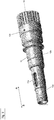
- the tool receiving device 4 again essentially contains an actuating cap 11, an elongated base body 12, a locking ring 13, first and second locking elements 14, 15 and a pressure element 16.
- the actuation cap 11 is designed essentially as a conical or conical sleeve which contains a first end 11a and a second end 11b.
- the actuating cap 11 is shown in a first embodiment.
- the Figures 14a and 14b show the actuation cap 11 in a second embodiment.
- the actuating cap 11 according to both the first and the second embodiment has a step 11d on an inner lateral surface 11c. As will be described in detail later, the step 11d serves as a contact surface or support surface for the pressure element 16.
- the elongated base body 12 serves to receive a rear end 6b of the tool 6 designed as a chisel. As will be described in detail below, the base body 12 also serves to receive the locking ring 13, the first and second locking elements 14, 15 and the pressure element 16.
- the base body 12 is essentially designed in the form of a tube which has a first and second section 12a, 12b. Both the first section 12a and the second section 12b each include first and second ends.
- the first section 12a has a smaller outer and inner diameter than the second section 12b.
- the first end of the first section 12a forms a front end of the base body 12.
- the second end of the first section 12a is connected to the first end of the second section 12b.
- the second end of the second section 12b in turn forms the rear end of the base body 12.
- the first section 12a of the base body 12 contains a first and a second radial opening 17a, 17b.
- the first and second openings 17a, 17b are elongated and positioned opposite one another.
- the base body 12 is shown in a first embodiment.
- the Figure 17 shows the actuation cap 11 in a second embodiment.
- the base body 12 according to the first and second embodiment differs essentially in that the base body 12 contains an annular toothing 18 at the rear end.
- the toothing 18 serves for the rotationally fixed connection of the base body 12 to a housing of the hammer mechanism 8.
- the first and second locking elements 14, 15 essentially have a cuboid base body with a front end 19a, a rear end 19b, an upper end 19c and a lower end 19d.
- the locking elements 14, 15 are used for releasable Connecting the base body 12 to the rear end 6b of the tool 6 when the rear end 6b of the tool 6 is located in the tool holding device 4.
- the locking elements 14, 15 are shown in a first embodiment.
- the Figures 16a and 16b show the locking elements 14, 15 in a second embodiment.
- the locking elements 14, 15 are shown in a third embodiment.
- the locking elements 14, 15 can also be referred to as pawls and serve to releasably connect the tool 6 to the base body 12.
- the locking element 14, 15 shown contains three steps 20 rising in the direction A at the upper end.
- the first and second locking elements 14, 15 are identical to one another.
- the locking element 14, 15 shown according to the second embodiment has essentially a flat basic shape.
- the locking element 14, 15 according to the second embodiment contains a flattened contact surface 21.
- the locking element 14, 15 contains a recess 22 on a left and a right side surface.
- the recess 22 can also be referred to as a groove or recess. As will be described later in detail, these depressions 22 serve to establish a releasable connection with the pressure element 16.
- the locking element 14, 15 shown according to the third embodiment corresponds essentially to the locking element 14, 15 according to the second embodiment, since it also has a flat basic shape. At a front end 19a, the locking element 14, 15 according to the third embodiment also has a flattened contact surface 21. At a rear end 19b, the locking element 14, 15 also has a respective recess 22 on a left and a right side surface. In contrast to the locking element 14, 15 according to the second embodiment, the locking element 14, 15 according to the third embodiment contains an elevation 23 which extends perpendicular to the longitudinal extension of the basic shape of the locking element 14, 15. In addition to the depressions 22 on the right and left side surfaces, this elevation 23 serves for an improved connection of the locking element 14, 15 to the pressing element 16.
- the locking ring 13 is designed essentially as a sleeve and essentially serves to fix the first and second locking elements 14, 15 in a locking position in which the tool 6 is held in the base body with the aid of the locking elements 14, 15.
- Figure 8 shows the locking ring 13 in a first embodiment.
- the inner lateral surface 13a of the locking ring 13 according to the first embodiment is also designed in a stepped manner and corresponds to the upper end 19c of the first and second locking elements 14, 15 according to the first embodiment.
- FIGS 15a and 15b the locking ring 13 is shown in a second embodiment.
- the locking ring 13 according to the second embodiment has a flattened plane on an inner lateral surface 13a.
- the angle of the flattened plane corresponds to the angle of the flattened contact surface 21 at the front end 19a of the locking element 14, 15 according to the second embodiment.
- the pressure element 16 is designed essentially as a ring made of an elastic material.
- the pressing element 16 designed as a ring is either completely or at least partially made of an elastic material.
- the elastic material can be an elastomer or rubber.
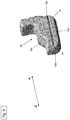
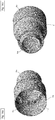
- the pressing element 16 shown according to a first embodiment is configured in an annular manner and has a first and a second surface side 16a, 16b. On the first surface side 16a, a first and second cutout 24a, 24b are provided, which are positioned opposite one another and extend radially over the entire first surface side 16a.
- the recess 24a, 24b can also be referred to as a groove.
- An annular groove 25 is provided on the second surface side 16b.
- the pressing element 16 shown according to the second embodiment is also configured in an annular manner and also contains a first and a second surface side 16a, 16b.
- First and second cutouts 24a, 24b are provided opposite one another on the first surface side 16a.
- the first and second cutouts 24a, 24b which can each also be referred to as a groove, extend in the radial direction.
- the recesses 24a, 24b serve as receiving areas for the respective rear end 19b of the locking elements 14, 15. Both the first and the second recess 24a, 24b each contain an elevation 26.
- the elevation 26 serves as a spring device to press the locking element 14, 15 in direction B when the rear end 19c of the locking element 14, 15 is located in the recess 24a, 24b of the pressure element 16.
- the elevation 26 in the first and second cutouts 24a, 24b extends in the axial direction B only up to half the height of the cutout 24a, 24b. In other words: the elevation 26 is half as high as the recess 24a, 24b.
- 13a and 13b shown protrudes a lip 27 from the left and right side of the recess 24a, 24b over the recess 24a, 24b.
- the lips 27 can as Lip elements or are referred to as a holding device.
- the length of the lips 27 is selected so that an opening is created between the free ends of the lips 27.
- the lips 27 serve as a holding device for the locking elements 14, 15 on the pressure element 16.
- two connecting elements 28 in the form of elevations are contained on the first surface side.
- the connecting elements 28 are arranged opposite one another and are positioned offset by 90 ° with respect to the two recesses 24a, 24b.
- the connecting elements 28 serve to connect the pressure element 16 to the actuating cap 11 in a rotationally fixed manner.
- Two annular steps 28a, 28b are provided on the second surface side 16b of the pressure element 16.
- the pressing element 16 shown according to the third embodiment is likewise configured in an annular manner and also contains a first and a second surface side 16a, 16b.
- the configuration of the pressing element 16 according to the third embodiment is essentially identical to the pressing element 16 according to the second embodiment.
- the lips 27 of the two recesses 24a, 24b are made longer, so that the respective free ends of the lips 27 almost close the recesses 24a, 24b and almost no opening between the free ends of the lips 27 are provided above the respective recesses 24a, 24b.
- the pressing element 16 does not contain any elevation 26 in the two recesses 24a, 24b.
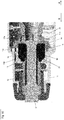
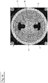
- the tool holder 4 or a front portion of the machine tool 1 according to a first embodiment is shown in an assembled state.
- the first locking element 14 is positioned in the first radial opening 17a of the base body 12 and the second locking element 15 is positioned in the second radial opening 17b of the base body 12.
- the two locking elements 14, 15 can each be positioned in a locking position or in a release position.
- the locking ring 13 is positioned above the base body 12 and is arranged in the direction B behind the locking elements 14, 15.
- the inner lateral surface 13a of the locking ring 13 is designed step-shaped according to the first embodiment, so that it corresponds to the step-shaped upper end 19c of the locking element 14, 15.
- the upper end 19c of the The shape of the locking element 14, 15 matches the inner jacket surface 13a of the locking ring 13.
- the pressing element 16 is also positioned above the base body 12.
- the pressing element 16 is arranged in the direction B in front of the locking elements 14, 15.
- the rear end 19c of the respective first and second locking elements 14, 15 rests in the recesses 24a, 24b of the pressure element 16.
- a spiral spring 29 is positioned in direction B behind the pressure element 16.
- the spiral spring 29 can also be referred to as a spring or spring element.
- the spiral spring 29 presses in the direction B on the pressure element 16.
- the pressure element 16 is pressed against the locking elements 14, 15.
- the actuation cap 11 according to the first embodiment is also arranged over the base body 12.
- the actuating cap 11 is shown configured conically and has a step 11d in the inner lateral surface 11c, cf. Figure 7a .
- the actuation cap 11 is positioned such that a front portion 11a of the actuation cap lies between the locking ring 13 and the pressure element 16.
- the step 11d rests on the rear end 19c of the respective locking element 14, 15.
- Figure 2 shows the first and second locking elements 14, 15 in the locking position when the rear end 6b of the tool 6 designed as a chisel is to be held in the tool holding device 4.
- the step 11d on the inside 11c of the actuating cap 11 presses the first and second locking elements 14.15 and the pressing element 16 against the spring force of the spiral spring 29 in direction A.
- the two openings 17a , 17b are designed as an elongated hole on the base body 12, the locking elements 14, 15 can be displaced in the axial direction A or B without the locking elements 14, 15 moving in the radial direction.
- the locking elements 14, 15 When the locking elements 14, 15 are no longer in engagement with the locking ring 13, the locking elements 14, 15 can finally move in the radial direction. When the two locking elements 14, 15 have moved in the radial direction, the two locking elements 14, 15 are no longer in the locking position, but in the release position. In the release position, the rear end 6b of the tool 6 designed as a chisel is no longer held in the tool holding device 4 by the locking elements 14, 15 and the tool 6 can be removed from the tool holding device 4 in direction B.
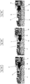
- Figures 10 , 11 , 12a, 12b and 12c the tool holding device 4 or a front part of the machine tool 1 according to a second embodiment is shown in an assembled state.
- the tool holding device 4 or the front part of the machine tool 1 according to the second embodiment essentially corresponds to the tool holding device 4 or the front part of the machine tool 1 according to the first embodiment.
- Figure 10 , 11 and 12b shows the first and second locking elements 14, 15 in the locking position when the rear end 6b of the tool 6 designed as a chisel is to be held in the tool holding device 4.
- Both the first and the second locking element 14, 15 are positioned so that the flattened contact surface 21 on the front end 19a of the locking element 14, 15 rests on the flattened plane on the inner lateral surface 13a of the locking ring 13.
- the spring 29 presses the pressure element 16 in direction B onto the locking elements 14, 15 and thus the locking elements 14, 15 against the locking ring 13.
- the step 11d presses on the inner lateral surface 11c of the actuation cap 11 as a contact surface on the pressure element 16 and presses the pressure element 16 against the spring force of the spring 29 in the direction A.
- the rear end 19b of the locking element 14, 15 is positioned in the recess 24a, 24b of the pressure element 16 (according to the second embodiment) that the lips 27 on the recess 24a, 24b each into one of the recess 22 on the engage the left and right side surfaces of the locking element 14, 15.
- the material of the pressure element 16 is to be selected so that the lips 27 are at least so flexible or movable that the rear end 19b of the locking element 14, 15 can be brought past the lips 27 into the recess 24a, 24b of the pressure element 16.
- the material must be selected so that the lips 27 offer at least enough resistance that the rear end 19b of the locking element 14, 15 only passes the two lips 27 and out of the recess 24a, 24b of the Pressure element 16 can be pulled.
- the pressing element 16 can also pull the first and second locking elements 24a, 24b in the direction A.
- the first and second locking elements 14, 15 move in direction A, the two locking elements 14, 15 are no longer in engagement with the locking ring 13, so that the locking elements 14, 15 can move in the radial direction from the rear end 6b of the inserted tool 6 , see. Figure 12c .
- the two locking elements 14, 15 have moved in the radial direction, the two locking elements 14, 15 are in the Release position so that the tool 6 can be removed from the tool holding device 4.
- the tool holding device 4 or a front part of the machine tool 1 according to a third embodiment is shown in an assembled state.
- the tool holding device 4 or the front part of the machine tool 1 according to the third embodiment essentially corresponds to the tool holding device 4 or the front part of the machine tool 1 according to the second embodiment.
- the mode of operation for moving the locking elements 14, 15 from the locking position into the release position is identical both in the case of the tool receiving device 4 according to the second and third embodiment.
- the first and second locking elements 14, 15 have an elevation 23 at the rear end 19b. This elevation 23 serves to ensure an improved connection or better form-fitting connection of the locking elements 14, 15 with the pressure element 16.
- the upper or free end of the elevation 23 protrudes at the rear end 19b of the locking element 14, 15 in the radial direction in the recess 24a, 24b of the pressure element 16.
- the positive connection between the locking element 14, 15 and the pressure element 16 is thus improved.
Landscapes
- Engineering & Computer Science (AREA)
- Mechanical Engineering (AREA)
- Percussive Tools And Related Accessories (AREA)
Priority Applications (5)
| Application Number | Priority Date | Filing Date | Title |
|---|---|---|---|
| EP20170492.1A EP3900882A1 (fr) | 2020-04-21 | 2020-04-21 | Élément d'appui pour machine-outils |
| US17/916,964 US12138768B2 (en) | 2020-04-21 | 2021-04-07 | Press-on element for a power tool |
| CN202180028661.3A CN115397622B (zh) | 2020-04-21 | 2021-04-07 | 用于动力工具的按压元件 |
| EP21717074.5A EP4139093A1 (fr) | 2020-04-21 | 2021-04-07 | Élément de pression pour une machine-outil |
| PCT/EP2021/059079 WO2021213806A1 (fr) | 2020-04-21 | 2021-04-07 | Élément de pression pour une machine-outil |
Applications Claiming Priority (1)
| Application Number | Priority Date | Filing Date | Title |
|---|---|---|---|
| EP20170492.1A EP3900882A1 (fr) | 2020-04-21 | 2020-04-21 | Élément d'appui pour machine-outils |
Publications (1)
| Publication Number | Publication Date |
|---|---|
| EP3900882A1 true EP3900882A1 (fr) | 2021-10-27 |
Family
ID=70390804
Family Applications (2)
| Application Number | Title | Priority Date | Filing Date |
|---|---|---|---|
| EP20170492.1A Withdrawn EP3900882A1 (fr) | 2020-04-21 | 2020-04-21 | Élément d'appui pour machine-outils |
| EP21717074.5A Pending EP4139093A1 (fr) | 2020-04-21 | 2021-04-07 | Élément de pression pour une machine-outil |
Family Applications After (1)
| Application Number | Title | Priority Date | Filing Date |
|---|---|---|---|
| EP21717074.5A Pending EP4139093A1 (fr) | 2020-04-21 | 2021-04-07 | Élément de pression pour une machine-outil |
Country Status (4)
| Country | Link |
|---|---|
| US (1) | US12138768B2 (fr) |
| EP (2) | EP3900882A1 (fr) |
| CN (1) | CN115397622B (fr) |
| WO (1) | WO2021213806A1 (fr) |
Citations (4)
| Publication number | Priority date | Publication date | Assignee | Title |
|---|---|---|---|---|
| EP1184136A1 (fr) * | 2000-09-04 | 2002-03-06 | HILTI Aktiengesellschaft | Outil main à percussion avec porte-outil |
| GB2444849A (en) * | 2006-12-15 | 2008-06-18 | Bosch Gmbh Robert | Electric hand tool machine having a tool locking system |
| DE102007028486A1 (de) * | 2007-06-21 | 2008-12-24 | Robert Bosch Gmbh | Werkzeughalter für ein Elektrowerkzeug, insbesondere für einen Meißel- und/oder Bohrhammer |
| US20130206436A1 (en) * | 2012-02-10 | 2013-08-15 | Milwaukee Electric Tool Corporation | Bit retention assembly for rotary hammer |
Family Cites Families (13)
| Publication number | Priority date | Publication date | Assignee | Title |
|---|---|---|---|---|
| DE19827172B4 (de) * | 1998-06-18 | 2006-11-09 | Robert Bosch Gmbh | Werkzeughalter, insbesondere für Bohr-oder Schlaghämmer |
| DE10001191C2 (de) * | 2000-01-14 | 2002-04-04 | Bosch Gmbh Robert | Handwerkzeugmaschine mit einer schlagend und/oder drehend antreibbaren Werkzeughalterung |
| GB0105547D0 (en) * | 2001-03-07 | 2001-04-25 | Black & Decker Inc | Tool holder for a rotary hammer or a chisel hammer |
| JP4438638B2 (ja) * | 2005-02-01 | 2010-03-24 | 日立工機株式会社 | 打撃工具 |
| JP5171085B2 (ja) * | 2007-03-28 | 2013-03-27 | 株式会社マキタ | 打撃工具 |
| DE102007000453A1 (de) * | 2007-08-20 | 2009-02-26 | Hilti Aktiengesellschaft | Wechselbare Werkzeugaufnahme |
| US7861799B2 (en) * | 2008-03-21 | 2011-01-04 | Makita Corporation | Impact tool |
| JP5147488B2 (ja) * | 2008-03-27 | 2013-02-20 | 株式会社マキタ | 作業工具 |
| SE534844C2 (sv) * | 2010-05-28 | 2012-01-17 | Atlas Copco Rock Drills Ab | Bergborrmaskin, löstagbar patron, stoppning och borrigg innefattande bergborrmaskinen |
| DE102014224931A1 (de) * | 2014-12-04 | 2016-06-09 | Robert Bosch Gmbh | Handwerkzeugmaschine mit einer Drehmomentkupplung |
| DE102018203522A1 (de) * | 2018-03-08 | 2019-09-12 | Robert Bosch Gmbh | Handwerkzeugmaschine |
| US11583987B2 (en) * | 2018-04-18 | 2023-02-21 | Raymond Stoner | Impact hammer system |
| GB201812437D0 (en) * | 2018-07-31 | 2018-09-12 | Black & Decker Inc | Hammer drill |
-
2020
- 2020-04-21 EP EP20170492.1A patent/EP3900882A1/fr not_active Withdrawn
-
2021
- 2021-04-07 CN CN202180028661.3A patent/CN115397622B/zh active Active
- 2021-04-07 EP EP21717074.5A patent/EP4139093A1/fr active Pending
- 2021-04-07 US US17/916,964 patent/US12138768B2/en active Active
- 2021-04-07 WO PCT/EP2021/059079 patent/WO2021213806A1/fr not_active Ceased
Patent Citations (4)
| Publication number | Priority date | Publication date | Assignee | Title |
|---|---|---|---|---|
| EP1184136A1 (fr) * | 2000-09-04 | 2002-03-06 | HILTI Aktiengesellschaft | Outil main à percussion avec porte-outil |
| GB2444849A (en) * | 2006-12-15 | 2008-06-18 | Bosch Gmbh Robert | Electric hand tool machine having a tool locking system |
| DE102007028486A1 (de) * | 2007-06-21 | 2008-12-24 | Robert Bosch Gmbh | Werkzeughalter für ein Elektrowerkzeug, insbesondere für einen Meißel- und/oder Bohrhammer |
| US20130206436A1 (en) * | 2012-02-10 | 2013-08-15 | Milwaukee Electric Tool Corporation | Bit retention assembly for rotary hammer |
Also Published As
| Publication number | Publication date |
|---|---|
| CN115397622B (zh) | 2025-05-02 |
| US20230158656A1 (en) | 2023-05-25 |
| CN115397622A (zh) | 2022-11-25 |
| WO2021213806A1 (fr) | 2021-10-28 |
| EP4139093A1 (fr) | 2023-03-01 |
| US12138768B2 (en) | 2024-11-12 |
Similar Documents
| Publication | Publication Date | Title |
|---|---|---|
| EP3261805B1 (fr) | Machine-outil portative | |
| EP0880426B1 (fr) | Porte-outil pour outils d'insertion sur machines travaillant par perforation et/ou percussion | |
| EP2384861B1 (fr) | Porte-outil pour un marteau perforateur | |
| DE102009054923B4 (de) | Handwerkzeugmaschine | |
| DE19621610B4 (de) | Einrichtung zum Wechseln des Werkzeughalters an einer Handwerkzeugmaschine | |
| CH663918A5 (de) | Schlagbohreinrichtung. | |
| EP0494400A2 (fr) | Outil à main avec porte-outil détachable | |
| DE112011100488T5 (de) | Vorrichtung zum Festziehen von mit Gewinde versehenen Befestigungselementen | |
| EP3648928B1 (fr) | Outil de pose, kit pour système d'outil de pose et système d'outil de pose | |
| DE10043416A1 (de) | Schlagendes Handwerkzeuggerät mit Werkzeugaufnahme | |
| DE3422195A1 (de) | Schlagbohreinrichtung | |
| DE102013221697B4 (de) | Handwerkzeugmaschine mit einer Drehmomentkupplung | |
| DE69503272T2 (de) | Werkzeughalter für einen Bohrhammer und/oder Meisselhammer | |
| DE102019115386A1 (de) | Bedienschlüssel für stehende und angetriebene Werkzeughalter | |
| CH688404A5 (de) | Werkzeughalter. | |
| EP0487457A1 (fr) | Outil pour forer et ciseler | |
| DE102014217992B4 (de) | Akkupack für eine Handwerkzeugmaschine | |
| WO2017149061A1 (fr) | Carotteuse électrique à main | |
| EP0155402A1 (fr) | Perforatrice à percussion | |
| EP3456479A1 (fr) | Dispositif d'entraînement pour une machine-outil entraînée | |
| EP3461594A1 (fr) | Élément de réglage et dispositif d'entraînement pour une machine-outil entraînée | |
| EP4139093A1 (fr) | Élément de pression pour une machine-outil | |
| DE29708201U1 (de) | Schrittweiser kraftverstärkender Schraubstock in Planetengetriebezug-Bauart | |
| EP2011608A1 (fr) | Outil manuel doté d'un dispositif d'accouplement à patinage | |
| EP4201595A1 (fr) | Outil électrique portatif |
Legal Events
| Date | Code | Title | Description |
|---|---|---|---|
| PUAI | Public reference made under article 153(3) epc to a published international application that has entered the european phase |
Free format text: ORIGINAL CODE: 0009012 |
|
| STAA | Information on the status of an ep patent application or granted ep patent |
Free format text: STATUS: THE APPLICATION HAS BEEN PUBLISHED |
|
| AK | Designated contracting states |
Kind code of ref document: A1 Designated state(s): AL AT BE BG CH CY CZ DE DK EE ES FI FR GB GR HR HU IE IS IT LI LT LU LV MC MK MT NL NO PL PT RO RS SE SI SK SM TR |
|
| B565 | Issuance of search results under rule 164(2) epc |
Effective date: 20200925 |
|
| STAA | Information on the status of an ep patent application or granted ep patent |
Free format text: STATUS: THE APPLICATION IS DEEMED TO BE WITHDRAWN |
|
| 18D | Application deemed to be withdrawn |
Effective date: 20220429 |