EP3900910A1 - Extrudiervorrichtung - Google Patents
Extrudiervorrichtung Download PDFInfo
- Publication number
- EP3900910A1 EP3900910A1 EP20893821.7A EP20893821A EP3900910A1 EP 3900910 A1 EP3900910 A1 EP 3900910A1 EP 20893821 A EP20893821 A EP 20893821A EP 3900910 A1 EP3900910 A1 EP 3900910A1
- Authority
- EP
- European Patent Office
- Prior art keywords
- raw material
- barrel
- zone
- screw
- extruder
- Prior art date
- Legal status (The legal status is an assumption and is not a legal conclusion. Google has not performed a legal analysis and makes no representation as to the accuracy of the status listed.)
- Pending
Links
Images




Classifications
-
- B—PERFORMING OPERATIONS; TRANSPORTING
- B29—WORKING OF PLASTICS; WORKING OF SUBSTANCES IN A PLASTIC STATE IN GENERAL
- B29C—SHAPING OR JOINING OF PLASTICS; SHAPING OF MATERIAL IN A PLASTIC STATE, NOT OTHERWISE PROVIDED FOR; AFTER-TREATMENT OF THE SHAPED PRODUCTS, e.g. REPAIRING
- B29C48/00—Extrusion moulding, i.e. expressing the moulding material through a die or nozzle which imparts the desired form; Apparatus therefor
- B29C48/25—Component parts, details or accessories; Auxiliary operations
- B29C48/36—Means for plasticising or homogenising the moulding material or forcing it through the nozzle or die
- B29C48/50—Details of extruders
- B29C48/505—Screws
-
- B—PERFORMING OPERATIONS; TRANSPORTING
- B29—WORKING OF PLASTICS; WORKING OF SUBSTANCES IN A PLASTIC STATE IN GENERAL
- B29C—SHAPING OR JOINING OF PLASTICS; SHAPING OF MATERIAL IN A PLASTIC STATE, NOT OTHERWISE PROVIDED FOR; AFTER-TREATMENT OF THE SHAPED PRODUCTS, e.g. REPAIRING
- B29C48/00—Extrusion moulding, i.e. expressing the moulding material through a die or nozzle which imparts the desired form; Apparatus therefor
- B29C48/25—Component parts, details or accessories; Auxiliary operations
- B29C48/36—Means for plasticising or homogenising the moulding material or forcing it through the nozzle or die
- B29C48/395—Means for plasticising or homogenising the moulding material or forcing it through the nozzle or die using screws surrounded by a cooperating barrel, e.g. single screw extruders
- B29C48/397—Means for plasticising or homogenising the moulding material or forcing it through the nozzle or die using screws surrounded by a cooperating barrel, e.g. single screw extruders using a single screw
-
- B—PERFORMING OPERATIONS; TRANSPORTING
- B29—WORKING OF PLASTICS; WORKING OF SUBSTANCES IN A PLASTIC STATE IN GENERAL
- B29C—SHAPING OR JOINING OF PLASTICS; SHAPING OF MATERIAL IN A PLASTIC STATE, NOT OTHERWISE PROVIDED FOR; AFTER-TREATMENT OF THE SHAPED PRODUCTS, e.g. REPAIRING
- B29C48/00—Extrusion moulding, i.e. expressing the moulding material through a die or nozzle which imparts the desired form; Apparatus therefor
- B29C48/001—Combinations of extrusion moulding with other shaping operations
- B29C48/0022—Combinations of extrusion moulding with other shaping operations combined with cutting
-
- B—PERFORMING OPERATIONS; TRANSPORTING
- B29—WORKING OF PLASTICS; WORKING OF SUBSTANCES IN A PLASTIC STATE IN GENERAL
- B29C—SHAPING OR JOINING OF PLASTICS; SHAPING OF MATERIAL IN A PLASTIC STATE, NOT OTHERWISE PROVIDED FOR; AFTER-TREATMENT OF THE SHAPED PRODUCTS, e.g. REPAIRING
- B29C48/00—Extrusion moulding, i.e. expressing the moulding material through a die or nozzle which imparts the desired form; Apparatus therefor
- B29C48/25—Component parts, details or accessories; Auxiliary operations
- B29C48/36—Means for plasticising or homogenising the moulding material or forcing it through the nozzle or die
- B29C48/361—Means for plasticising or homogenising the moulding material or forcing it through the nozzle or die with the barrel or with a part thereof rotating
-
- B—PERFORMING OPERATIONS; TRANSPORTING
- B29—WORKING OF PLASTICS; WORKING OF SUBSTANCES IN A PLASTIC STATE IN GENERAL
- B29C—SHAPING OR JOINING OF PLASTICS; SHAPING OF MATERIAL IN A PLASTIC STATE, NOT OTHERWISE PROVIDED FOR; AFTER-TREATMENT OF THE SHAPED PRODUCTS, e.g. REPAIRING
- B29C48/00—Extrusion moulding, i.e. expressing the moulding material through a die or nozzle which imparts the desired form; Apparatus therefor
- B29C48/25—Component parts, details or accessories; Auxiliary operations
- B29C48/36—Means for plasticising or homogenising the moulding material or forcing it through the nozzle or die
- B29C48/50—Details of extruders
- B29C48/505—Screws
- B29C48/59—Screws characterised by details of the thread, i.e. the shape of a single thread of the material-feeding screw
-
- B—PERFORMING OPERATIONS; TRANSPORTING
- B29—WORKING OF PLASTICS; WORKING OF SUBSTANCES IN A PLASTIC STATE IN GENERAL
- B29C—SHAPING OR JOINING OF PLASTICS; SHAPING OF MATERIAL IN A PLASTIC STATE, NOT OTHERWISE PROVIDED FOR; AFTER-TREATMENT OF THE SHAPED PRODUCTS, e.g. REPAIRING
- B29C48/00—Extrusion moulding, i.e. expressing the moulding material through a die or nozzle which imparts the desired form; Apparatus therefor
- B29C48/25—Component parts, details or accessories; Auxiliary operations
- B29C48/36—Means for plasticising or homogenising the moulding material or forcing it through the nozzle or die
- B29C48/50—Details of extruders
- B29C48/68—Barrels or cylinders
- B29C48/6801—Barrels or cylinders characterised by the material or their manufacturing process
-
- B—PERFORMING OPERATIONS; TRANSPORTING
- B29—WORKING OF PLASTICS; WORKING OF SUBSTANCES IN A PLASTIC STATE IN GENERAL
- B29C—SHAPING OR JOINING OF PLASTICS; SHAPING OF MATERIAL IN A PLASTIC STATE, NOT OTHERWISE PROVIDED FOR; AFTER-TREATMENT OF THE SHAPED PRODUCTS, e.g. REPAIRING
- B29C48/00—Extrusion moulding, i.e. expressing the moulding material through a die or nozzle which imparts the desired form; Apparatus therefor
- B29C48/25—Component parts, details or accessories; Auxiliary operations
- B29C48/36—Means for plasticising or homogenising the moulding material or forcing it through the nozzle or die
- B29C48/50—Details of extruders
- B29C48/68—Barrels or cylinders
- B29C48/6803—Materials, coating or lining therefor
-
- B—PERFORMING OPERATIONS; TRANSPORTING
- B29—WORKING OF PLASTICS; WORKING OF SUBSTANCES IN A PLASTIC STATE IN GENERAL
- B29C—SHAPING OR JOINING OF PLASTICS; SHAPING OF MATERIAL IN A PLASTIC STATE, NOT OTHERWISE PROVIDED FOR; AFTER-TREATMENT OF THE SHAPED PRODUCTS, e.g. REPAIRING
- B29C48/00—Extrusion moulding, i.e. expressing the moulding material through a die or nozzle which imparts the desired form; Apparatus therefor
- B29C48/25—Component parts, details or accessories; Auxiliary operations
- B29C48/36—Means for plasticising or homogenising the moulding material or forcing it through the nozzle or die
- B29C48/50—Details of extruders
- B29C48/68—Barrels or cylinders
- B29C48/681—Barrels or cylinders for single screws
-
- B—PERFORMING OPERATIONS; TRANSPORTING
- B29—WORKING OF PLASTICS; WORKING OF SUBSTANCES IN A PLASTIC STATE IN GENERAL
- B29C—SHAPING OR JOINING OF PLASTICS; SHAPING OF MATERIAL IN A PLASTIC STATE, NOT OTHERWISE PROVIDED FOR; AFTER-TREATMENT OF THE SHAPED PRODUCTS, e.g. REPAIRING
- B29C48/00—Extrusion moulding, i.e. expressing the moulding material through a die or nozzle which imparts the desired form; Apparatus therefor
- B29C48/25—Component parts, details or accessories; Auxiliary operations
- B29C48/36—Means for plasticising or homogenising the moulding material or forcing it through the nozzle or die
- B29C48/50—Details of extruders
- B29C48/76—Venting, drying means; Degassing means
- B29C48/763—Vent constructions, e.g. venting means avoiding melt escape
-
- B—PERFORMING OPERATIONS; TRANSPORTING
- B29—WORKING OF PLASTICS; WORKING OF SUBSTANCES IN A PLASTIC STATE IN GENERAL
- B29C—SHAPING OR JOINING OF PLASTICS; SHAPING OF MATERIAL IN A PLASTIC STATE, NOT OTHERWISE PROVIDED FOR; AFTER-TREATMENT OF THE SHAPED PRODUCTS, e.g. REPAIRING
- B29C48/00—Extrusion moulding, i.e. expressing the moulding material through a die or nozzle which imparts the desired form; Apparatus therefor
- B29C48/25—Component parts, details or accessories; Auxiliary operations
- B29C48/36—Means for plasticising or homogenising the moulding material or forcing it through the nozzle or die
- B29C48/50—Details of extruders
- B29C48/76—Venting, drying means; Degassing means
- B29C48/765—Venting, drying means; Degassing means in the extruder apparatus
- B29C48/766—Venting, drying means; Degassing means in the extruder apparatus in screw extruders
- B29C48/767—Venting, drying means; Degassing means in the extruder apparatus in screw extruders through a degassing opening of a barrel
-
- B—PERFORMING OPERATIONS; TRANSPORTING
- B29—WORKING OF PLASTICS; WORKING OF SUBSTANCES IN A PLASTIC STATE IN GENERAL
- B29C—SHAPING OR JOINING OF PLASTICS; SHAPING OF MATERIAL IN A PLASTIC STATE, NOT OTHERWISE PROVIDED FOR; AFTER-TREATMENT OF THE SHAPED PRODUCTS, e.g. REPAIRING
- B29C48/00—Extrusion moulding, i.e. expressing the moulding material through a die or nozzle which imparts the desired form; Apparatus therefor
- B29C48/25—Component parts, details or accessories; Auxiliary operations
- B29C48/78—Thermal treatment of the extrusion moulding material or of preformed parts or layers, e.g. by heating or cooling
- B29C48/80—Thermal treatment of the extrusion moulding material or of preformed parts or layers, e.g. by heating or cooling at the plasticising zone, e.g. by heating cylinders
- B29C48/802—Heating
-
- B—PERFORMING OPERATIONS; TRANSPORTING
- B29—WORKING OF PLASTICS; WORKING OF SUBSTANCES IN A PLASTIC STATE IN GENERAL
- B29C—SHAPING OR JOINING OF PLASTICS; SHAPING OF MATERIAL IN A PLASTIC STATE, NOT OTHERWISE PROVIDED FOR; AFTER-TREATMENT OF THE SHAPED PRODUCTS, e.g. REPAIRING
- B29C48/00—Extrusion moulding, i.e. expressing the moulding material through a die or nozzle which imparts the desired form; Apparatus therefor
- B29C48/25—Component parts, details or accessories; Auxiliary operations
- B29C48/78—Thermal treatment of the extrusion moulding material or of preformed parts or layers, e.g. by heating or cooling
- B29C48/80—Thermal treatment of the extrusion moulding material or of preformed parts or layers, e.g. by heating or cooling at the plasticising zone, e.g. by heating cylinders
- B29C48/83—Heating or cooling the cylinders
-
- B—PERFORMING OPERATIONS; TRANSPORTING
- B29—WORKING OF PLASTICS; WORKING OF SUBSTANCES IN A PLASTIC STATE IN GENERAL
- B29C—SHAPING OR JOINING OF PLASTICS; SHAPING OF MATERIAL IN A PLASTIC STATE, NOT OTHERWISE PROVIDED FOR; AFTER-TREATMENT OF THE SHAPED PRODUCTS, e.g. REPAIRING
- B29C48/00—Extrusion moulding, i.e. expressing the moulding material through a die or nozzle which imparts the desired form; Apparatus therefor
- B29C48/25—Component parts, details or accessories; Auxiliary operations
- B29C48/78—Thermal treatment of the extrusion moulding material or of preformed parts or layers, e.g. by heating or cooling
- B29C48/80—Thermal treatment of the extrusion moulding material or of preformed parts or layers, e.g. by heating or cooling at the plasticising zone, e.g. by heating cylinders
- B29C48/83—Heating or cooling the cylinders
- B29C48/832—Heating
-
- B—PERFORMING OPERATIONS; TRANSPORTING
- B29—WORKING OF PLASTICS; WORKING OF SUBSTANCES IN A PLASTIC STATE IN GENERAL
- B29C—SHAPING OR JOINING OF PLASTICS; SHAPING OF MATERIAL IN A PLASTIC STATE, NOT OTHERWISE PROVIDED FOR; AFTER-TREATMENT OF THE SHAPED PRODUCTS, e.g. REPAIRING
- B29C48/00—Extrusion moulding, i.e. expressing the moulding material through a die or nozzle which imparts the desired form; Apparatus therefor
- B29C48/25—Component parts, details or accessories; Auxiliary operations
- B29C48/78—Thermal treatment of the extrusion moulding material or of preformed parts or layers, e.g. by heating or cooling
- B29C48/875—Thermal treatment of the extrusion moulding material or of preformed parts or layers, e.g. by heating or cooling for achieving a non-uniform temperature distribution, e.g. using barrels having both cooling and heating zones
-
- B—PERFORMING OPERATIONS; TRANSPORTING
- B29—WORKING OF PLASTICS; WORKING OF SUBSTANCES IN A PLASTIC STATE IN GENERAL
- B29C—SHAPING OR JOINING OF PLASTICS; SHAPING OF MATERIAL IN A PLASTIC STATE, NOT OTHERWISE PROVIDED FOR; AFTER-TREATMENT OF THE SHAPED PRODUCTS, e.g. REPAIRING
- B29C48/00—Extrusion moulding, i.e. expressing the moulding material through a die or nozzle which imparts the desired form; Apparatus therefor
- B29C48/25—Component parts, details or accessories; Auxiliary operations
- B29C48/88—Thermal treatment of the stream of extruded material, e.g. cooling
- B29C48/91—Heating, e.g. for cross linking
-
- B—PERFORMING OPERATIONS; TRANSPORTING
- B29—WORKING OF PLASTICS; WORKING OF SUBSTANCES IN A PLASTIC STATE IN GENERAL
- B29C—SHAPING OR JOINING OF PLASTICS; SHAPING OF MATERIAL IN A PLASTIC STATE, NOT OTHERWISE PROVIDED FOR; AFTER-TREATMENT OF THE SHAPED PRODUCTS, e.g. REPAIRING
- B29C48/00—Extrusion moulding, i.e. expressing the moulding material through a die or nozzle which imparts the desired form; Apparatus therefor
- B29C48/25—Component parts, details or accessories; Auxiliary operations
- B29C48/92—Measuring, controlling or regulating
-
- B—PERFORMING OPERATIONS; TRANSPORTING
- B29—WORKING OF PLASTICS; WORKING OF SUBSTANCES IN A PLASTIC STATE IN GENERAL
- B29K—INDEXING SCHEME ASSOCIATED WITH SUBCLASSES B29B, B29C OR B29D, RELATING TO MOULDING MATERIALS OR TO MATERIALS FOR MOULDS, REINFORCEMENTS, FILLERS OR PREFORMED PARTS, e.g. INSERTS
- B29K2055/00—Use of specific polymers obtained by polymerisation reactions only involving carbon-to-carbon unsaturated bonds, not provided for in a single one of main groups B29K2023/00 - B29K2049/00, e.g. having a vinyl group, as moulding material
- B29K2055/02—ABS polymers, i.e. acrylonitrile-butadiene-styrene polymers
Definitions
- the present invention relates to an extruder that extrudes a solid raw material containing moisture and, more specifically, to an extruder having a zone in which a sealing membrane is formed from the raw material within a barrel to prevent backflow of moisture discharged from the raw material.
- thermoplastic resin produced by emulsion polymerization the manufactured thermoplastic resin is generally obtained in a latex state with a dispersion medium.
- raw materials contain a large amount of moisture.
- the process of manufacturing a thermoplastic resin comprises a dehydration and drying process for removing the moisture.
- an extruder illustrated in FIG. 1 is used, as needed, to heat and press the dried raw material, and thus, the dried raw material is obtained in a form of pellets.
- the extruder is configured such that a hopper 2, through which a raw material is put, is installed on one side of a tubular barrel 1, and the raw material is discharged to a discharge port (a left outlet in the drawing) through an internal screw 5.
- the raw material injected through the hopper 2 is heated by a heater (not shown) mounted to the inside or outside of the barrel and pressed by the screw 5. Accordingly, water vapor generated from moisture remaining in the dried raw material is separated while the dried raw material is moved by the screw 5. The separated water vapor is discharged to the outside through a vent part 6 disposed away from the hopper 2.
- a check plate 4 for minimizing an effect of the backflow of water vapor and an introduction screw 3 for forcibly injecting the raw material into the barrel are additionally equipped in the hopper 2.
- the object of the present invention is to provide an extruder capable of directly extruding a raw material that is dehydrated without a drying process and preventing water vapor, which is separated from the raw material, from flowing back to a hopper, thereby improving extrusion efficiency.
- the present invention provides an extruder configured to extrude a solid raw material containing moisture, the extruder comprising: a barrel having a hollow tubular shape in a longitudinal direction, wherein a hopper into which a raw material is put is coupled to one side of the barrel, and a discharge port through which a dehydrated raw material is discharged is provided on the other side of the barrel; a rod-shaped screw provided with screw threads on an outer circumferential surface thereof so that the screw is mounted within the barrel to transfer a raw material put into the hopper to the discharge port while axially rotating in one direction; a vent part disposed at one point between the hopper and the discharge port to discharge vapor generated within the barrel to the outside; and a heater part mounted on the barrel to heat the raw material, wherein the raw material introduced into the barrel through the hopper is gradually heated by the heater part while being transferred within the barrel through the screw, a kneading zone, in which raw materials transferred by the screw threads are compressed, is formed
- the kneading zone is disposed between the vent part and the hopper.
- a distance between the kneading zone and the vent part is less than three times a diameter of the barrel. Also, a distance between the kneading zone and the hopper is greater than five times a diameter of the barrel.
- the screw comprises: a first forward zone in which the screw threads are provided to transfer the raw material, which is put from the hopper, toward the discharge port when rotating axially; the kneading zone in which the screw threads are provided to compress the raw material, which is transferred from the first forward zone, when rotating axially; and a second forward zone in which the screw threads are provided to transfer the raw material, which passes through the kneading zone, toward the discharge port when rotating axially.
- the kneading zone may comprise a neutral zone in which the screw threads are provided on the outer circumferential surface of the rod shape to induce the raw material to rotate at the same place. Also, the kneading zone may comprise a reverse zone in which the screw threads are provided on the outer circumferential surface of the rod shape to transfer the raw material in a direction opposite to the direction in which the raw material is transferred by the screw threads provided in the first forward zone.
- the kneading zone may be constituted by connecting the neutral zone, in which the screw threads are provided on the outer circumferential surface of the rod shape to induce the raw material to rotate at the same place, to the reverse zone, in which the screw threads are provided on the outer circumferential surface of the rod shape to transfer the raw material in the direction opposite to the direction in which the raw material is transferred by the screw threads provided in the first forward zone, wherein the neutral zone is connected to the first forward zone, and the reverse zone is connected to the second forward zone.
- the screw may further comprise a sub-kneading zone in which the screw threads are provided to recompress the raw material, which is transferred from the second forward zone, when rotating axially.
- a distance between the sub-kneading zone and the vent part is greater than three times a diameter of the barrel.
- the screw further may comprise a third forward zone in which the screw threads are provided to transfer the raw material, which passes through the sub-kneading zone, toward the discharge port when rotating axially, and a sub-vent part configured to discharge impurities contained in the raw material to the outside may be provided in the barrel within a range in which the third forward zone is formed.
- a distance between the sub-kneading zone and the sub-vent part is less than three times a diameter of the barrel.
- the extruder may further comprise a pulverizer configured to pulverize the dried raw material that is discharged from the discharge port of the barrel.
- the sealing membrane is formed in the kneading zone while the raw material is being extruded inside the barrel, and thus, the backflow of the water vapor to the hopper may be prevented or minimized.
- the kneading zone may comprise one of the neutral zone or the reverse zone or the combination thereof and thus may be selectively utilized depending on the state or properties of the raw material.
- the screw according to the present invention may further comprise the sub-kneading zone, and thus, it is possible to form the additional sealing membranes, thereby more efficiently preventing the backflow of the water vapor.
- the present invention relates to an extruder for extruding a solid raw material containing moisture, and hereinafter, the extruder according to the present invention will be described in more detail with reference to the accompanying drawings.
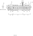
- the extruder according to the present invention comprises a barrel 10, a screw 30 mounted inside the barrel 10, a vent part 40 through which water vapor inside the barrel 10 is discharged to the outside, and a heater part 60 for heating the barrel 10. Also, a sealing membrane is formed from a melted resin within the barrel 10.
- the barrel 10 has a hollow tubular shape in the longitudinal direction.
- a hopper 20, through which a raw material is put, is coupled to one side of the barrel 10, and a discharge port 11 for discharging a dehydrated raw material is provided on the other side thereof.
- the barrel 10 is made of metal having excellent chemical resistance to prevent corrosion due to volatile substances and water vapor discharged from the raw material, or is manufactured such that the inner surface thereof is coated with a protective material.
- the barrel 10 is manufactured to have rigidity enough to withstand heat and pressure generated from the inside.
- the screw 30 has a bar shape and a structure in which screw threads M (31, 32, 33) are provided on the outer circumferential surface thereof. Also, the screw 20 transfers the raw material, which is put from the hopper 20, toward a discharge port 11 while being mounted inside the barrel 10 and axially rotating in one direction.
- the screw threads M having a spiral shape are provided on the outer circumferential surface of the screw 30 in the longitudinal direction.
- a region, in which the screw threads M are formed in a direction to move the raw material toward the discharge port, is divided into forward zones (sections F1, F2, and F3).
- a region, in which the screw threads are formed to only rotate the raw material without moving the raw material or to move the raw material in a reverse direction is defined as a kneading zone 30A.
- FIG. 3 illustrating an enlarged view of a section K1 in which the kneading zone 30A of FIG. 2 is provided and FIG. 4 illustrating shapes of the screw threads applicable to the kneading zone 30A
- the screw threads provided in the kneading zone 30A are configured to compress the raw material rather than transfer the raw material.
- the upper figure of FIG. 3 is a state in which a case is coupled to the exterior of the screw threads and the lower figure is a state in which the case is removed.
- the kneading zone 30A comprises a neutral zone in which neutral screw threads 32 are provided on the outer circumferential surface of the rod shape to induce the raw material to rotate at the same place and/or a reverse zone in which reverse screw threads 33 are provided on the outer circumferential surface of the rod shape to transfer the raw material in the opposite direction. That is, the present invention provides embodiment 1, 2, and 3 having, respectively, a configuration in which only the neutral zone is provided in the kneading zone, a configuration in which only the reverse zone is provided in the kneading zone, and a configuration in which the neutral zone and the reverse zone are combined.
- the neutral screw threads 32 provided in the neutral zone may not have a form in which screw threads are connected to each other in a spiral shape, but have an individually separated form (that is, a form in which annular screw threads are connected to each other at intervals).
- an individually separated form that is, a form in which annular screw threads are connected to each other at intervals.
- the reverse screw threads 33 defined in the reverse zone are provided in a direction opposite to that of the screw threads provided in the forward zone.
- the reverse screw threads 33 having the above-described form generates force for transferring the raw material in the opposite direction when the raw material reaches.
- the raw material When the raw material reaches the kneading zone 30A in which the neutral zone and/or the reverse zone are provided, the raw material is pressed as agglomerating together with raw material continuously supplied from the forward zone on a rear side.
- the screw 30 may have sections F1, F2, and F3 in which a plurality of forward zones are provided and sections K1 and K2 in which a plurality of kneading zones are provided. That is, as illustrated in FIG. 2 , there is provided a structure in which a first forward zone (section F1), a kneading zone (section K1), a second forward zone (section F2), a sub-kneading zone (section K2), and a third forward zone (section F3) are arranged in the order from the hopper 20.
- Forward screw threads 31 are provided in the first forward zone to transfer the raw material, which is put from the hopper 20, toward the discharge port 11 when rotating axially, and the neutral screw threads 32 or the reverse screw threads 33 are provided in the kneading zone 30A to compress the raw material, which is transferred from the first forward zone, when the screw 30 rotates axially.
- the neutral screw threads 32 or the reverse screw threads 33 provided in the sub-kneading zone 30B may be similar to those in the kneading zone 30A, and the forward screw threads provided in the second forward zone and the third forward zone are similar to those in the first forward zone.
- vent part 40 is mounted to the barrel 10 so that steam (and separated gas, etc.) is discharged after the raw material passes through the kneading zone 30A from the hopper 20.
- the vent part 40 may have a simple tubular shape that is open upward from the barrel 10, but an openable and closable valve, an exhaust device that forcibly discharges water vapor, and a safety vent that opens only at a certain pressure or higher may be coupled thereto.
- the heater part 60 for generating heat is coupled to the outer surface of the barrel 10 (or inside thereof).
- the heater part 60 may be a device that converts electrical energy into thermal energy or a device that receives a heat source from the outside to heat the barrel.
- a plurality of heater parts 60 are mounted over the entirety of the barrel, and temperatures of the heater parts 60 may be individually controlled. Accordingly, the barrel 10 is configured such that a temperature control is possible for each of the sections (the forward zones and the kneading zones).
- the raw material stored in the hopper 20 when the raw material stored in the hopper 20 is supplied into the barrel 10, the raw material is transferred through the screw 30 inside the barrel 10 and heated (and cooled) to a target temperature by the heater part 60.
- the raw material passes through the first forward zone and reaches the kneading zone 30A, the raw material is pressed in a heated state by raw materials continuously supplied from a rear side and by the rotation force of the screw 30.
- the heated and pressed raw material is melt in the kneading zone 30A (or before reaching the kneading zone), and at least a portion or almost all of the raw material is phase-changed into a liquid state.
- the raw material which has been heated and pressed in the kneading zone 30A, is forced to be spread radially due to centrifugal force created in the kneading zone 30A.
- a solid raw material, water vapor separated from the raw material, etc. in a front portion of the kneading zone 30A are spread into the space between the screw 30 and the barrel 10. Also, as heat and pressure are continuously applied, most of the solid raw material in a rear portion of the kneading zone 30A (close to the discharge port) is melted into a liquid state.
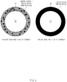
- a sealing membrane which shields the transverse section of the barrel 10, is formed from the melted raw material by centrifugal force.
- the thickness and the formation position of the sealing membrane may vary depending on the rotation speed of the screw 30, the heating temperature of the heater part 60, and the configuration of the screw threads provided in the kneading zone 30A. Also, in the barrel 10, the sealing membrane is formed in a changeable state rather than in a fixed state.
- the sealing membrane is formed as a liquid film, and as a raw material is continuously supplied, the raw material, which has formed the sealing membrane first, passes through the kneading zone 30A and is then discharged toward the second forward zone. Then, a raw material supplied later is changed into a liquid state and maintains the sealing membrane while supplementing the raw material discharged earlier.
- the heating temperature of the heater part 60 and the axial rotation speed of the screw are controlled.
- the liquid raw material is continuously transferred along the screw 30, but the gas-state water vapor (and the gas generated during the phase change) is discharged to the outside through the vent part 40.
- the backflow of the water vapor to the hopper 20 is prevented by the sealing membrane formed in the kneading zone 30A.
- the raw material which reaches the sub-kneading zone 30B, forms a sealing membrane again in the sub-kneading zone 30B and is then discharged to the discharge port 11 through the third forward zone. While being transferred through the third forward zone, impurities (residual monomers, etc.) contained in the raw material, gas generated during the phase change, surplus water vapor, and the like are discharged to the outside through a sub-vent part 50.
- the raw material discharged to the discharge port 11 of the barrel 10 is cooled after the water vapor, gas, and the like are separated therefrom, and then discharged in a form of a solid mass.
- the raw material discharged in the form of a solid mass is cut into pellets having a certain size by a pulverizer 70 that pulverizes a dehydrated (dried) raw material.
- a distance from the hopper 20 to the kneading zone 30A is set to 5D to 10D.
- a distance between the kneading zone 30A and the vent part 40 is set to 3D or less
- a distance between the vent part 40 and the sub-kneading zone 30B is set to 3D or more
- a distance between the sub-kneading zone 30B and the sub-vent part 50 is set to 3D or less.
- these relative distances are not limited to the ranges described above and may change depending on the length and axial rotation speed of the screw 30, a state of the raw material, an output of the heater part 60, and the like.
- the sealing membrane is formed in the kneading zone 30A while the raw material is being dehydrated inside the barrel 10, and thus, the backflow of the water vapor to the hopper 20 may be prevented or minimized.
- the kneading zone 30A may comprise one of the neutral zone or the reverse zone, or a combination thereof and thus may be selectively utilized depending on the state or properties of the raw material.
- the screw 30 may further comprise the sub-kneading zone 30B, an additional sealing membrane may be formed.
- the water vapor may be discharged through the vent part 40 as much as possible while more efficiently preventing the backflow of water vapor.
- the extruder of the present invention since the moisture contained in the raw material is discharged through the vent part 40 simultaneously with the extrusion, it is possible to discharge impurities (residual monomers, etc.) contained in the raw material through the sub-vent part 50 as much as possible.
- the extruder of the present invention may be an apparatus for extruding thermoplastic resin.
- This thermoplastic resin may be thermoplastic resin that may be palletized through the extruder and, as a specific example, may be a diene-based graft copolymer.
- the diene-based graft copolymer may be an acrylonitrile butadiene styrene graft copolymer.
- the diene-based graft copolymer is generally manufactured through an emulsion polymerization method, and is obtained in a latex state in which colloidal particulates of the completely polymerized diene-based graft copolymer are dispersed in water that serves as a dispersion medium, that is, in a solid state containing moisture. Subsequently, the diene-based graft copolymer, which has been obtained in the latex state, is obtained in a form of dry powder through aggregation, dehydration, and dry steps.
- the diene-based graft copolymer obtained in the form of dry powder has a problem that the caking phenomenon occurs due to aggregation and coagulation between the dry powder when stored for a long period of time.
- the extruder of the present invention may effectively remove the moisture from the solid raw material containing moisture, simultaneously with the extrusion.
- the diene-based graft copolymer is extruded by using the extruder of the present invention, it is not necessary to dry the diene-based graft copolymer obtained in the latex state, and it is possible to directly extrude the dehydrated diene-based graft copolymer.
- the diene-based graft copolymer extruded by using the extruder of the present invention has bulk density higher than that of the dry powder and thus may prevent the caking phenomenon from occurring when stored for a long period of time.
- the extruder of the present invention may be more effective to obtain the thermoplastic resin, the diene-based graft copolymer as a specific example, and the acrylonitrile butadiene styrene graft copolymer as a further specific example.
Landscapes
- Engineering & Computer Science (AREA)
- Mechanical Engineering (AREA)
- Physics & Mathematics (AREA)
- Thermal Sciences (AREA)
- Manufacturing & Machinery (AREA)
- Extrusion Moulding Of Plastics Or The Like (AREA)
Applications Claiming Priority (2)
| Application Number | Priority Date | Filing Date | Title |
|---|---|---|---|
| KR1020190152012A KR102714652B1 (ko) | 2019-11-25 | 2019-11-25 | 압출장치 |
| PCT/KR2020/010746 WO2021107332A1 (ko) | 2019-11-25 | 2020-08-13 | 압출장치 |
Publications (2)
| Publication Number | Publication Date |
|---|---|
| EP3900910A1 true EP3900910A1 (de) | 2021-10-27 |
| EP3900910A4 EP3900910A4 (de) | 2022-03-16 |
Family
ID=76129724
Family Applications (1)
| Application Number | Title | Priority Date | Filing Date |
|---|---|---|---|
| EP20893821.7A Pending EP3900910A4 (de) | 2019-11-25 | 2020-08-13 | Extrudiervorrichtung |
Country Status (7)
| Country | Link |
|---|---|
| US (1) | US12390975B2 (de) |
| EP (1) | EP3900910A4 (de) |
| JP (1) | JP7233798B2 (de) |
| KR (1) | KR102714652B1 (de) |
| CN (1) | CN113412183A (de) |
| MY (1) | MY209050A (de) |
| WO (1) | WO2021107332A1 (de) |
Cited By (1)
| Publication number | Priority date | Publication date | Assignee | Title |
|---|---|---|---|---|
| CN115431491A (zh) * | 2022-08-30 | 2022-12-06 | 滁州燕荣塑料科技有限公司 | 一种增强增韧尼龙材料成型加工机 |
Families Citing this family (1)
| Publication number | Priority date | Publication date | Assignee | Title |
|---|---|---|---|---|
| CN119283337B (zh) * | 2024-11-28 | 2025-05-30 | 浙江光明塑料机械有限公司 | 一种塑料回收的超长小锥度双筒螺杆挤出机 |
Family Cites Families (54)
| Publication number | Priority date | Publication date | Assignee | Title |
|---|---|---|---|---|
| US4173445A (en) * | 1978-07-17 | 1979-11-06 | Monsanto Company | Plastics extrusion apparatus |
| DE3332629A1 (de) * | 1983-09-09 | 1985-03-28 | Hermann Berstorff Maschinenbau Gmbh, 3000 Hannover | Verfahren und vorrichtung zum pulverisieren von polymeren |
| JPS61279524A (ja) * | 1985-06-05 | 1986-12-10 | Jgc Corp | 雑固体廃棄物の押出成形装置 |
| CS250997B1 (cs) * | 1985-12-21 | 1987-05-14 | Ladislav Pospisil | Způsob výroby směsi polypropylenu a nízkohustotního polyetylénu |
| JP3187920B2 (ja) | 1992-02-28 | 2001-07-16 | 三菱重工業株式会社 | 同方向回転二軸押出機 |
| IT1256083B (it) | 1992-07-31 | 1995-11-27 | Enichem Polimeri | Procedimento per funzionalizzare polimeri dell'etilene |
| JP3528134B2 (ja) * | 1994-06-06 | 2004-05-17 | 東芝機械株式会社 | 含水ポリマ押出装置およびこれを用いた押出方法 |
| JPH07329150A (ja) | 1994-06-13 | 1995-12-19 | Japan Steel Works Ltd:The | パウダー原料を用いた溶融樹脂押出方法及び装置 |
| JP3472391B2 (ja) | 1995-07-19 | 2003-12-02 | 東芝機械株式会社 | 2軸押出機及びその2軸押出機を利用した押出方法 |
| JPH09117954A (ja) | 1995-10-25 | 1997-05-06 | Toshiba Mach Co Ltd | 2軸押出機 |
| JP3434418B2 (ja) * | 1996-07-24 | 2003-08-11 | 東芝機械株式会社 | 同方向回転2軸押出機による高融点樹脂の脱水システム |
| JP3680887B2 (ja) * | 1997-02-07 | 2005-08-10 | 東芝機械株式会社 | 組立式脱水バレル |
| KR100322860B1 (ko) | 1997-04-09 | 2002-07-08 | 노리쓰기 세끼도 | 열가소성수지용사출성형장치 |
| JPH11188769A (ja) | 1997-12-25 | 1999-07-13 | Haruna:Kk | 射出成形機、ペレット投入装置ユニット、射出成形システム、射出成形物品及び射出成形方法 |
| JP2000318017A (ja) | 1999-05-07 | 2000-11-21 | Toshiba Mach Co Ltd | 2軸押出機とその2軸押出機による熱可塑性樹脂原料の脱水方法 |
| DE60116057T2 (de) * | 2000-02-09 | 2006-07-20 | Davis-Standard Corp., Pawcatuck | Stabiles rückstellungsverhalten aufweisender extruderzylindertemperaturregler |
| JP5084078B2 (ja) * | 2001-09-03 | 2012-11-28 | 旭化成ケミカルズ株式会社 | 難燃性ポリカーボネート樹脂組成物の製造方法 |
| JP4004804B2 (ja) | 2002-01-22 | 2007-11-07 | 旭化成ケミカルズ株式会社 | 難燃性ポリカーボネート樹脂組成物の製造方法 |
| JP2004042460A (ja) | 2002-07-12 | 2004-02-12 | Toshiba Mach Co Ltd | 押出成形方法およびその装置 |
| KR100541055B1 (ko) | 2002-09-04 | 2006-01-10 | 제일모직주식회사 | Abs 수지 조성물 펠렛을 제조하기 위한 개선된 압출기 |
| US6908573B2 (en) | 2003-04-17 | 2005-06-21 | General Electric | Polymeric resin blends and methods of manufacture thereof |
| AU2003271148A1 (en) | 2003-10-09 | 2005-04-27 | Misawa Homes Co., Ltd. | Extrusion molding machine |
| KR20050074666A (ko) | 2004-01-14 | 2005-07-19 | 김계중 | 폐 플라스틱 재생을 위한 압출장치 |
| KR100568410B1 (ko) | 2004-01-28 | 2006-04-05 | 주식회사 엘지화학 | 높은 전환율을 가지며 고형분 함량이 높은 아크릴로니트릴-부타디엔-스티렌 라텍스의 제조방법 |
| KR100596702B1 (ko) | 2004-02-16 | 2006-07-04 | 김학수 | 통기성 필름 제조 장치 |
| JP4707377B2 (ja) | 2004-12-02 | 2011-06-22 | 東芝機械株式会社 | 熱可塑性樹脂原料のフィルム等の成形方法 |
| JP2008302555A (ja) | 2007-06-06 | 2008-12-18 | Japan Steel Works Ltd:The | 廃プラスチックの処理方法及びその装置 |
| JP2009184303A (ja) * | 2008-02-08 | 2009-08-20 | Japan Steel Works Ltd:The | 二軸スクリュ押出機における脱揮成分の分離方法及び装置 |
| JP2010194794A (ja) | 2009-02-24 | 2010-09-09 | Ishida Co Ltd | 回収ポリエステルから成形品を製造する方法 |
| JP5832733B2 (ja) | 2010-09-17 | 2015-12-16 | 富士フイルム株式会社 | ポリエステルフィルムの製造方法 |
| JP4977786B1 (ja) | 2011-02-09 | 2012-07-18 | 三菱エンジニアリングプラスチックス株式会社 | ポリカーボネート樹脂ペレットの製造方法 |
| WO2012120637A1 (ja) * | 2011-03-08 | 2012-09-13 | 日立マクセル株式会社 | 混練装置、及び熱可塑性樹脂成形体の製造方法 |
| JP5587267B2 (ja) | 2011-08-31 | 2014-09-10 | 富士フイルム株式会社 | ポリエステル樹脂の製造方法 |
| JP2013119201A (ja) * | 2011-12-07 | 2013-06-17 | Konica Minolta Advanced Layers Inc | 熱可塑性樹脂フィルムの製造方法 |
| CN103158208B (zh) | 2011-12-15 | 2015-09-23 | 中国石油天然气股份有限公司 | 一种适于abs接枝聚合物干燥的方法及设备 |
| CN102529062B (zh) | 2012-01-30 | 2015-05-20 | 天津万塑新材料科技有限公司 | 用于挤塑加工尼龙而无需对尼龙进行烘干处理的螺杆组合 |
| KR101324079B1 (ko) | 2012-02-14 | 2013-10-31 | 주식회사 제로텍 | 이물질 제거와 수분 제거가 가능한 폐합성수지 용융 압출 장치 |
| JP3185887U (ja) | 2013-06-27 | 2013-09-05 | 有限会社セレジン長崎 | スクリュ式押出機 |
| CN104004288A (zh) | 2014-05-05 | 2014-08-27 | 上海锦湖日丽塑料有限公司 | 超高光泽阻燃abs树脂及其制备方法 |
| JP6033895B2 (ja) | 2015-01-13 | 2016-11-30 | 株式会社日本製鋼所 | ベントを備えた押出機 |
| KR101681207B1 (ko) * | 2015-03-03 | 2016-11-30 | 고려이엔알 주식회사 | 고체연료 성형기 |
| KR101542834B1 (ko) | 2015-03-05 | 2015-08-07 | 유태욱 | 고분자 수지 내 수분 제거 장치 및 제거 방법 |
| ITBO20150247A1 (it) * | 2015-05-13 | 2016-11-13 | Sacmi | Apparato e metodo di ispezione ottica di un estrusore. |
| CN106279553A (zh) | 2015-05-27 | 2017-01-04 | 上海华谊聚合物有限公司 | 一种低残留单体abs树脂及其制备方法 |
| EP3383923B2 (de) | 2015-12-02 | 2023-04-12 | INEOS Styrolution Group GmbH | Verfahren zur herstellung von abs-kunststoffen mit verbesserten eigenschaften |
| JP2017165048A (ja) | 2016-03-18 | 2017-09-21 | トヨタ自動車株式会社 | 繊維強化樹脂材の製造方法と製造装置 |
| KR101830958B1 (ko) | 2016-03-31 | 2018-02-23 | 한국생산기술연구원 | 유연한 유리섬유(Glass Wool)를 포함하는 플라스틱 재료 제조용 압출기 |
| JP2019104107A (ja) | 2016-04-15 | 2019-06-27 | 住友化学株式会社 | 樹脂組成物の製造方法および二軸混練押出機 |
| ITUA20164096A1 (it) * | 2016-06-03 | 2017-12-03 | Nexxus Channel S R L | Vite per estrusore di materiali polimerici, estrusore di materiali polimerici comprendente detta vite e metodo per realizzare prodotti polimerici estrusi |
| KR101913907B1 (ko) | 2016-07-08 | 2018-10-31 | 롯데첨단소재(주) | 열가소성 수지 조성물의 제조방법 및 이로부터 제조된 열가소성 수지 조성물 |
| KR102068308B1 (ko) | 2016-09-23 | 2020-01-20 | 주식회사 엘지화학 | 고분자의 잔류 모노머 함량 제어방법 |
| KR101873209B1 (ko) | 2016-11-30 | 2018-07-03 | 윤기환 | 압출공정을 구비한 사출 성형장치 |
| KR20180076645A (ko) | 2016-12-28 | 2018-07-06 | 주식회사 엘지화학 | 내열성 스티렌계 수지 제조방법 |
| JP7172405B2 (ja) | 2018-10-09 | 2022-11-16 | 東レ株式会社 | 熱可塑性樹脂組成物の製造方法 |
-
2019
- 2019-11-25 KR KR1020190152012A patent/KR102714652B1/ko active Active
-
2020
- 2020-08-13 MY MYPI2021004810A patent/MY209050A/en unknown
- 2020-08-13 CN CN202080013509.3A patent/CN113412183A/zh active Pending
- 2020-08-13 EP EP20893821.7A patent/EP3900910A4/de active Pending
- 2020-08-13 WO PCT/KR2020/010746 patent/WO2021107332A1/ko not_active Ceased
- 2020-08-13 US US17/428,205 patent/US12390975B2/en active Active
- 2020-08-13 JP JP2021543430A patent/JP7233798B2/ja active Active
Cited By (1)
| Publication number | Priority date | Publication date | Assignee | Title |
|---|---|---|---|---|
| CN115431491A (zh) * | 2022-08-30 | 2022-12-06 | 滁州燕荣塑料科技有限公司 | 一种增强增韧尼龙材料成型加工机 |
Also Published As
| Publication number | Publication date |
|---|---|
| US12390975B2 (en) | 2025-08-19 |
| MY209050A (en) | 2025-06-18 |
| US20220118671A1 (en) | 2022-04-21 |
| KR102714652B1 (ko) | 2024-10-10 |
| EP3900910A4 (de) | 2022-03-16 |
| KR20210063643A (ko) | 2021-06-02 |
| JP2022518565A (ja) | 2022-03-15 |
| WO2021107332A1 (ko) | 2021-06-03 |
| JP7233798B2 (ja) | 2023-03-07 |
| CN113412183A (zh) | 2021-09-17 |
Similar Documents
| Publication | Publication Date | Title |
|---|---|---|
| US12304111B2 (en) | Extruder | |
| US3814563A (en) | Apparatus for treating elastomeric materials | |
| US6220745B1 (en) | Device and monitoring system for removing liquid from high melting point resin by means of co-rotating twin screw extruder | |
| JP3863581B2 (ja) | 熱可塑性プラスチック溶融物と水相からなる2相液状混合物の脱水方法 | |
| US3431599A (en) | Extrusion method and apparatus | |
| JP4252016B2 (ja) | 押出機 | |
| US2765491A (en) | Extrusion apparatus | |
| US12390975B2 (en) | Extruder | |
| KR102219278B1 (ko) | 다층의 추진제 입자를 제조하는 방법 | |
| US2895167A (en) | Filtering liner for barrels of extrusion machines | |
| US3300810A (en) | Extruder | |
| CN101391484A (zh) | 排气挤出机中的驱动装置的设置 | |
| US5887972A (en) | Extruder for plastic granules | |
| US3115675A (en) | Extrusion apparatus with degasification elements | |
| EP1768823B1 (de) | Vorrichtung zum plastifizieren von polypropylen enthaltendem thermoplastischem harz | |
| JP3597070B2 (ja) | 耐衝撃性熱可塑性樹脂の製造装置およびその方法 | |
| US3834440A (en) | Method for drying polymeric materials | |
| CA2094985A1 (en) | Screw element having shearing and scraping flights | |
| DE1579106A1 (de) | Schneckenpresse zur Vorentwaesserung und Trocknung von Synthesekautschuk | |
| US20200055227A1 (en) | Vent Type Extruder and Method of Manufacturing Cable Jacket Using the Same | |
| CN1208176C (zh) | 增强均质化的热塑泡沫材料挤压螺杆 | |
| CN211074634U (zh) | 一种物料挤出机 | |
| TH2101005819A (th) | เครื่องอัดรีด | |
| RU2495608C1 (ru) | Экспандер | |
| JP2618174B2 (ja) | 連続混練機用ロータ |
Legal Events
| Date | Code | Title | Description |
|---|---|---|---|
| STAA | Information on the status of an ep patent application or granted ep patent |
Free format text: STATUS: THE INTERNATIONAL PUBLICATION HAS BEEN MADE |
|
| PUAI | Public reference made under article 153(3) epc to a published international application that has entered the european phase |
Free format text: ORIGINAL CODE: 0009012 |
|
| STAA | Information on the status of an ep patent application or granted ep patent |
Free format text: STATUS: REQUEST FOR EXAMINATION WAS MADE |
|
| 17P | Request for examination filed |
Effective date: 20210723 |
|
| AK | Designated contracting states |
Kind code of ref document: A1 Designated state(s): AL AT BE BG CH CY CZ DE DK EE ES FI FR GB GR HR HU IE IS IT LI LT LU LV MC MK MT NL NO PL PT RO RS SE SI SK SM TR |
|
| RIC1 | Information provided on ipc code assigned before grant |
Ipc: B29C 48/55 20190101ALI20220203BHEP Ipc: B29C 48/57 20190101ALI20220203BHEP Ipc: B29C 48/00 20190101ALI20220203BHEP Ipc: B29C 48/76 20190101ALI20220203BHEP Ipc: B29C 48/92 20190101ALI20220203BHEP Ipc: B29C 48/91 20190101ALI20220203BHEP Ipc: B29C 48/505 20190101ALI20220203BHEP Ipc: B29C 48/36 20190101AFI20220203BHEP |
|
| A4 | Supplementary search report drawn up and despatched |
Effective date: 20220210 |
|
| DAV | Request for validation of the european patent (deleted) | ||
| DAX | Request for extension of the european patent (deleted) | ||
| STAA | Information on the status of an ep patent application or granted ep patent |
Free format text: STATUS: EXAMINATION IS IN PROGRESS |
|
| 17Q | First examination report despatched |
Effective date: 20240221 |