EP3900934B1 - Dispositif de génération d'une impression sur une matière d'impression et procédé de génération d'une pluralité de cavités sur une forme d'impression dotée d'une matrice magnétique - Google Patents
Dispositif de génération d'une impression sur une matière d'impression et procédé de génération d'une pluralité de cavités sur une forme d'impression dotée d'une matrice magnétique Download PDFInfo
- Publication number
- EP3900934B1 EP3900934B1 EP20170576.1A EP20170576A EP3900934B1 EP 3900934 B1 EP3900934 B1 EP 3900934B1 EP 20170576 A EP20170576 A EP 20170576A EP 3900934 B1 EP3900934 B1 EP 3900934B1
- Authority
- EP
- European Patent Office
- Prior art keywords
- printing
- cavities
- magnetic
- raster
- Prior art date
- Legal status (The legal status is an assumption and is not a legal conclusion. Google has not performed a legal analysis and makes no representation as to the accuracy of the status listed.)
- Active
Links
Images





Classifications
-
- B—PERFORMING OPERATIONS; TRANSPORTING
- B41—PRINTING; LINING MACHINES; TYPEWRITERS; STAMPS
- B41F—PRINTING MACHINES OR PRESSES
- B41F1/00—Platen presses, i.e. presses in which printing is effected by at least one essentially-flat pressure-applying member co-operating with a flat type-bed
-
- B—PERFORMING OPERATIONS; TRANSPORTING
- B41—PRINTING; LINING MACHINES; TYPEWRITERS; STAMPS
- B41F—PRINTING MACHINES OR PRESSES
- B41F9/00—Rotary intaglio printing presses
- B41F9/001—Heliostatic printing
-
- B—PERFORMING OPERATIONS; TRANSPORTING
- B41—PRINTING; LINING MACHINES; TYPEWRITERS; STAMPS
- B41M—PRINTING, DUPLICATING, MARKING, OR COPYING PROCESSES; COLOUR PRINTING
- B41M1/00—Inking and printing with a printer's forme
- B41M1/10—Intaglio printing ; Gravure printing
-
- B—PERFORMING OPERATIONS; TRANSPORTING
- B41—PRINTING; LINING MACHINES; TYPEWRITERS; STAMPS
- B41N—PRINTING PLATES OR FOILS; MATERIALS FOR SURFACES USED IN PRINTING MACHINES FOR PRINTING, INKING, DAMPING, OR THE LIKE; PREPARING SUCH SURFACES FOR USE AND CONSERVING THEM
- B41N1/00—Printing plates or foils; Materials therefor
-
- B—PERFORMING OPERATIONS; TRANSPORTING
- B41—PRINTING; LINING MACHINES; TYPEWRITERS; STAMPS
- B41N—PRINTING PLATES OR FOILS; MATERIALS FOR SURFACES USED IN PRINTING MACHINES FOR PRINTING, INKING, DAMPING, OR THE LIKE; PREPARING SUCH SURFACES FOR USE AND CONSERVING THEM
- B41N1/00—Printing plates or foils; Materials therefor
- B41N1/04—Printing plates or foils; Materials therefor metallic
- B41N1/06—Printing plates or foils; Materials therefor metallic for relief printing or intaglio printing
-
- B—PERFORMING OPERATIONS; TRANSPORTING
- B41—PRINTING; LINING MACHINES; TYPEWRITERS; STAMPS
- B41N—PRINTING PLATES OR FOILS; MATERIALS FOR SURFACES USED IN PRINTING MACHINES FOR PRINTING, INKING, DAMPING, OR THE LIKE; PREPARING SUCH SURFACES FOR USE AND CONSERVING THEM
- B41N1/00—Printing plates or foils; Materials therefor
- B41N1/16—Curved printing plates, especially cylinders
-
- G—PHYSICS
- G03—PHOTOGRAPHY; CINEMATOGRAPHY; ANALOGOUS TECHNIQUES USING WAVES OTHER THAN OPTICAL WAVES; ELECTROGRAPHY; HOLOGRAPHY
- G03G—ELECTROGRAPHY; ELECTROPHOTOGRAPHY; MAGNETOGRAPHY
- G03G19/00—Processes using magnetic patterns; Apparatus therefor, i.e. magnetography
Definitions
- the invention relates to a device for generating a print on a printing material, the device comprising at least one printing forme, at least one device for dispensing a print medium, at least one device for data transmission and at least one device for control.
- the printing form has a printing body, a magnetic grid and a cover layer, the magnetic grid being applied to the surface of the printing body and the cover layer being located above the magnetic grid. Magnetic particles are contained in the top layer. According to the invention, each raster point of the magnetic raster can be controlled independently of the other raster points of the magnetic raster and the cover layer is set up to form a multiplicity of cavities for receiving a print medium.
- the invention further relates to a method for producing a large number of cavities on a printing form, the printing form comprising a printing body, a magnetic grid and a cover layer, the magnetic grid being located on the surface of the printing body and a cover layer being applied over the magnetic grid, the magnetic has particles.
- Each grid point of the magnetic grid can be electrically addressed independently of the other grid points of the magnetic field grid via a controller.
- a voltage is applied to each grid point of the magnetic grid at the position of which a cavity is to be formed on the surface of the printing form. The voltage applied creates a magnetic field that attracts the magnetic particles in the top layer, causing a cavity to form on the surface of the printing form at this position.
- printing technology includes all processes for duplicating print samples, such as letterpress, offset printing, gravure printing, flexographic printing, screen printing and digital printing. Different methods are used in these printing techniques in order to transfer a printing medium, such as an ink, to a printing material.
- a printing medium such as an ink
- the areas of application of printing technology are very diverse. For example, the printing of print media, wallpaper or the like is known. But in the production of floor laminate or wall and ceiling cladding elements, the so-called Decor print used. Wood-based panels are often printed here. There are several approaches to decorating wood-based panels. In the past, wood-based panels were often coated with a decorative paper, with the variety of decorative papers with different patterns being unlimited. As an alternative to the use of decorative papers on wood-based panels, the possibility of direct printing on wood-based panels has developed, with printing on paper and its subsequent laminating or direct coating on the wood-based panels being omitted.
- the printing techniques that are mainly used here are gravure and digital printing. For the use of this printing process, the print decor is available as a digital template that depicts the colors and color distribution of the print decor.
- the gravure printing process is a printing technique in which the elements to be reproduced are present as cavities, i.e. indentations, in a static pressure body, e.g. a printing roller or a printing plate, which is provided with a printing medium, such as ink, before printing.
- a static pressure body e.g. a printing roller or a printing plate
- the printing medium is primarily in the depressions and is transferred to the object to be printed, the printing substrate, due to the contact pressure of the printing form and adhesive forces.
- gravure printing it is possible to print mixed colors and color gradients.
- the printing media used for gravure printing, in particular the pigment-containing liquids such as inks, are available in a wide range and are relatively inexpensive.
- a printing roller As an example, a steel cylinder is encased in a copper layer around 2 mm thick, which is called base copper. Either an engravable copper layer of about 100 ⁇ m is galvanized on this inner copper layer or a removable Ballard skin is applied.
- Ballard skin can be removed after printing and replaced with a new one.
- the print pattern is broken down into tiny printing elements called cells, surrounded by non-printing elements called ridges.
- the print pattern is accordingly broken down into a grid in gravure printing.
- the cells are filled with the print medium before printing and excess print medium is usually wiped off with a squeegee.
- the squeegee consists of a steel ruler corresponding to the length of the printing cylinder.
- the print pattern is applied in the form of a grid to the copper layer that can be engraved or to the Ballard skin. This can be done by chemical etching, electromechanically or by means of a laser. In In any case, a static printing form is created with an unchangeable arrangement of cells.
- a separation file is created at the beginning of the printing process, in which the print pattern is broken down into the primary colors to be printed.
- the arrangement of the cells on the printing form is different for each color to be printed, so in conventional gravure printing an associated Ballard skin must be made for each color.
- the individual primary colors are then printed one after the other on the substrate.
- the Ballard skin of a print roller can be replaced. To do this, the Ballard skin must first be removed from the roller body, then the roller body is cleaned and provided with a new separating layer. A new Ballard skin can then be applied to the new release liner.
- the width/length of the print pattern is limited to the size of the printing form. Either by the circumference and width of the printing roller or by the dimensions of the printing plate.
- the circumference of the print roller limits the print data length of the print pattern and the width of the print roller limits the print data width of the print pattern.
- print data length to mean the length of the finished printed print pattern
- print data width to mean the width of the finished printed print pattern. If a larger print pattern is to be printed than the printing form allows, this must be done in parts. This procedure is very complex and error-prone, since the transitions between the individually printed parts of the print pattern must be maintained exactly in order to obtain a harmonious print result.
- repeat designates a constantly recurring same print pattern.
- print rollers are used for printing with a repeat, with the repeat being determined by the circumference of the print roller.
- the maximum print data length of the print pattern that recurs in the repeat can be as long as the circumference of the roller.
- a repeat i.e. the print pattern
- the print data length of the print pattern must be selected so that the circumference of the print roller is optimally used. This is the only way to ensure an economical way of working.
- gravure printing therefore also has the disadvantages mentioned.
- digital printing With digital printing, the print pattern is transferred directly from a computer to a digital printer such as a laser printer or inkjet printer. In digital printing, therefore, the use of static printing forms and thus the limitations in the print data length and print data width of the print pattern are no longer necessary. Digital printing thus offers a high degree of flexibility and variability with regard to the print motifs and does not entail any restrictions in the repeat.
- digital printing is also known, for example, for printing wood-based panels.
- the EP 2 181 852 B1 for example, relates to a digital printing process for printing on flat wood-based panels.
- the flat panels are printed directly with a digital printer.
- the EP 2 636 531 A1 also relates to a digital printing method for printing a surface of a workpiece.
- a print roller is provided with a print pattern by a digital printer and this print pattern is then applied to the workpiece by the print roller.
- the basic colors cyan, magenta, yellow and black are usually used in digital printing.
- the CMYK color model is a subtractive color model, with the abbreviation CMYK standing for the three color components cyan, magenta, yellow and the black component key as the color depth.
- CMYK a subtractive color model
- CMYK standing for the three color components cyan, magenta, yellow and the black component key as the color depth.
- the print medium is applied drop by drop to the substrate.
- the drop exits the print head nozzle it typically forms a ligament that, in the best case, is sucked into the drop.
- the ligament atomizes and forms a fine mist.
- This spray fouls the nozzles of the print head and other elements of the printing device. Over time this worsens the print quality and cleaning of the printer is necessary. This is time-consuming and therefore incurs costs.
- the spray mist accumulates in the surrounding air over time and poses a health risk to the workers who operate the machines.
- Part of the ligament can also detach in the front part of the drop and then forms a so-called satellite on the substrate. This degrades the print image and thus the quality of the print.
- Another problem is the condensation of water vapor on the print head, which can lead to poor print quality or even damage the print head.
- Digital printing can therefore eliminate some of the disadvantages of gravure printing, but it also has disadvantages in terms of print quality.
- the object of the present invention is therefore to overcome the disadvantages of the prior art and to provide a device and a method for producing a print on a substrate which combines the robust and economical gravure printing technique with great flexibility with regard to the printable Print patterns of digital printing united.
- the device according to the invention for generating a print on a printing material comprises at least one printing forme, at least one device for dispensing a print medium, at least one device for data transmission and at least one device for control.
- the printing form of the present invention comprises a printing body, a magnetic grid and a cover layer.
- the pressure body is a pressure body as is known from gravure printing.
- the pressure body is preferably a pressure roller or a pressure plate.
- the pressure body is a pressure roller.
- Steel cylinders, for example, are typical here.
- the pressure body can have all the usual dimensions in the field of printing.
- a magnetic grid is applied to the surface of the pressure body.
- the magnetic grid is preferably exactly the same size as the surface of the pressure body and thus covers it with a precise fit.
- the magnetic grid is designed in such a way that a grid is formed from an electrically conductive material and each grid point can be addressed individually electrically. Grid points are understood to be the nodal points of the grid, while the grid cells are spanned between the grid points.
- An adjustable voltage is applied to each grid point, which creates a magnetic field. Since each raster point can be controlled individually, a magnetic field is generated by applying a voltage to precisely defined raster points corresponding to precisely defined positions in the top layer.
- the magnetic grid can be applied firmly to the pressure body or else be embedded in a material which is applied as a layer to the pressure body.
- the material in which the magnetic grid is embedded is preferably a flexible material that can adapt to the shape of the pressure hull, for example in shape of a foil.
- the material in which the magnetic grid is embedded is preferably non-magnetic and also non-magnetizable.
- a top layer is located over the magnetic grid, the top layer having magnetic particles.
- the cover layer is preferably exactly as large as the magnetic grid, which means it completely covers it.
- the magnetic grid and the overlying covering layer are just large enough to cover the entire surface of the printing body. This has the advantage that the entire surface of the printing body can be used for printing on a printing material.
- the cover layer has a height such that cavities can be formed in it.
- the top layer therefore has a height of between 30 and 150 ⁇ m, preferably between 40 and 120 ⁇ m, particularly preferably between 50 and 100 ⁇ m.
- the cover layer has a material from the group consisting of elastomers and smart materials.
- the magnetic particles are firmly embedded in this material.
- the material of the cover layer has such an elasticity that it can be deformed by external forces.
- the material can be deformed at least partially by an applied magnetic field, in that the magnetic particles firmly embedded in the material are attracted by a magnetic field and thereby deform the surrounding material.
- indentations in the form of cavities can thus be formed on the surface of the cover layer.
- the cavities represent depressions in the cover layer, which are designed in such a way that they can accommodate a print medium.
- the cavities are designed as cups, as are known from conventional gravure printing.
- the cups are also used to hold a print medium in a printing process.
- the cover layer has a permanently elastic film made from an elastomer.
- the cover layer can be designed as a permanently elastic film made of an elastomer, in which magnetic particles are embedded.
- Smart materials are materials that can change their mechanical properties. When exposed to an electrical voltage, these materials change from being non-deformable state to a state where they are malleable.
- Known materials here are hybrid materials made of metal and liquid.
- An example of such a hybrid material is a combination of gold, in which numerous pores and channels are formed by etching, with a conductive liquid, such as saline or a dilute acid, filled in the pores and channels.
- the top layer contains magnetic particles which are distributed in the top layer.
- the magnetic particles have a diameter of between 5 nm and 5 ⁇ m, preferably between 200 nm and 1 ⁇ m, particularly preferably between 300 nm and 1 ⁇ m. Any kind of magnetic material such as iron or iron oxides that is of an appropriate size is suitable as the magnetic particle.
- the magnetic particles are preferably evenly distributed in the top layer. In a further embodiment of the invention, however, the magnetic particles can also be unevenly distributed in the top layer. The density of the magnetic particles located in the top layer is so great that the summed force of at least a subset of the magnetic particles when attracted by a magnetic field is so great that the material in which they are embedded deforms can be. According to the invention, each grid point is therefore able to form at least one cavity.
- the voltage applied to the grid points can be regulated.
- two states can be generated first.
- the applied voltage is zero at one or more grid points, so no magnetic field is generated at these points and the cover layer of the printing form is not deformed at these positions, ie no cavities are formed.
- the second state a voltage is applied to one or more grid points, so a magnetic field is generated at these points and the top layer is deformed accordingly.
- the deformation takes place in such a way that cavities are formed at the corresponding points on the cover layer of the printing form.
- the strength of the applied voltage also regulates the strength of the magnetic field, so that deeper cavities are formed with a stronger magnetic field than with a weaker magnetic field.
- the depth of the cavities can thus be regulated by regulating the strength of the applied voltage.
- the brightness values in a print pattern can advantageously be taken into account since, depending on the depth of the cavity, the volume of the cavity can be varied and different quantities of print medium can thus be accommodated in the cavity.
- conventional gravure printing this is done in an analogous way by engraving cells with different depths.
- the depth of each cavity can be changed between two printing processes without having to convert the printing form. This is not possible in conventional gravure printing due to the engraving of the printing form.
- a new Ballard skin with a modified engraving has to be laboriously applied to the pressure hull.
- the printing form is therefore set up so that the depth and thus the volume of the cavities can be adjusted via the voltage applied to the grid nodes.
- the cavities on the surface of the cover layer have a depth in the range from 2 ⁇ m to 100 ⁇ m, preferably in the range from 2 ⁇ m to 80 ⁇ m, particularly preferably in the range from 2 ⁇ m to 80 ⁇ m.
- the cover layer also has areas made from a second material from the group consisting of thermoplastics and duroplastics.
- the second material is preferably not magnetizable and also has no magnetic particles.
- areas made of the second material are arranged in the areas of the grid points.
- the areas made of the second material are formed in such a way that when the cover layer is deformed by applying a voltage, the shape of the cavities that form is influenced by the shape of the areas made of the second material.
- the shape of the cavities can be influenced by the shaping of the regions made of the second material.
- the cavities in such a way that they can assume all the shapes of the wells known from conventional gravure printing. Since the shape of the cavities also affects their volume, different scoop volumes can be generated analogously to conventional gravure printing by varying the depth and/or shape of the cavities. The scoop volume is to be equated with the volume of the cavity.
- the scoop volume is determined by the gray levels in the color separation data.
- the volume of the individual cavities required for the printing process is therefore determined as a function of the gray levels of a print pattern or the separation data created from the print pattern. The depth and thus the volume of the cavities is then adjusted as described via the voltage applied to the grid points.
- the shape of the cavity describes both the shape of the cavity when the cover layer is viewed from above and the shape of the cavity when the cover layer is viewed in cross section.
- the printing form is therefore set up in such a way that the shape of the cavities can be influenced by the arrangement and shape of the areas of the cover layer that consist of the second material.
- the cavities preferably have a circular or elliptical area when the top layer is viewed from above.
- the cavities particularly preferably have an elliptical surface.
- the elliptical and the circular area are preferably used, with the elliptical shape producing the smoothest gradient between light and dark tones in a printing process.
- the cavities in a different shape, depending on the arrangement of the areas made of the second material in the cover layer. It is thus also possible to form cavities which have an angular surface when the cover layer is viewed from above. For example, a triangular, square, or polygonal area. If the cavities are angular, in a preferred embodiment they have a square surface when the cover layer is viewed from above.
- cavities can be formed which have all the cross sections known from conventional gravure printing.
- these cavities can be in the form of a pointed pyramid, truncated pyramid or in the form of a truncated pyramid with steep flanks or cavities with a pointed cap, with a normal cap or with a U-shape with steep flanks and a flat bottom.
- the arrangement of the areas made of the second material in the cover layer results in areas being formed in the cover layer which serve as webs between adjacent cavities.
- the webs represent the non-printing areas of the printing form. Webs are known from conventional gravure printing and are also used there to delimit adjacent cavities. The bars can stabilize the top layer of the printing form and thus make it easier to remove excess ink with a squeegee.
- the areas of the cover layer that consist of the second material are therefore arranged and shaped in the cover layer in such a way that they serve as webs between adjacent cavities.
- the cover layer can be designed as a permanently elastic film made of an elastomer, in which magnetic particles are embedded and which has areas made of a second material.
- the cover layer is set up to form a large number of cavities for receiving a print medium.
- the cavities are formed at the positions where they are necessary for printing a predetermined print pattern. Analogous to conventional gravure printing, each cavity reflects a printing point in the printing pattern.
- a typical roller used in conventional gravure printing has a screen with a screen ruling of 60 lpc, i.e. 60 lines per cm. For example, this results in 8,400 cavities in width and 7,800 cavities in circumference for a device according to the invention with a roller with a width of 140 cm and a circumference of 130 cm as the pressure body.
- the magnetic grid is designed so that 65,520,000 grid points are available, which can be controlled individually.
- the device is set up to form cavities with a grid width in the range from 10 lpc to 80 lpc, preferably in the range from 30 lpc to 70 lpc, particularly preferably with 60 lpc.
- the printing form also has a sensor.
- the sensor is suitable for exactly one position of the circumference of the roll determine. With the help of the sensor, it is advantageously possible to determine precisely at which point on the circumference of the roller it is currently printing.
- the device according to the invention also has a device for dispensing a pressure medium.
- the device for dispensing a print medium preferably has a container with a squeegee or lines for transporting the print medium.
- the device for dispensing a print medium has a container with a squeegee.
- the container contains the printing medium and the printing form dips into the printing medium in the container, so that the cavities on the cover layer of the printing medium are completely flooded with the printing medium.
- the squeegee then removes the excess printing medium so that there is only printing medium in the cavities, but the cover layer between the cavities is free of printing medium.
- the use of a container with a squeegee is particularly advantageous if the pressure body is a cylinder.
- Embodiments of squeegees are known from the prior art, for example, the squeegee can be designed in the form of a steel ruler. However, squeegees made of elastic or soft materials that are suitable for scraping off powder are also known. Suitable elastic materials are, for example, felt, rubber or other plastics.
- the device for dispensing a pressure medium has a container with an air curtain.
- the container contains the printing medium and the printing form dips into the printing medium in the container, so that the cavities on the cover layer of the printing medium are completely flooded with the printing medium. The excess pressure medium is then removed by the air curtain.
- the embodiments in which the device for dispensing a printing medium has a container with a squeegee or a container with an air curtain are particularly advantageous if the printing forme has a pressure roller as the pressure body.
- the device for dispensing a print medium has at least one applicator roller and one doctor blade.
- the print medium is applied to the printing form with the at least one applicator roller and the excess print medium is then removed with the aid of the at least one doctor blade.
- This embodiment is particularly advantageous if the printing form has a printing plate as the printing body.
- the device for delivering a pressure medium has lines for transporting the pressure medium.
- the lines run advantageously through the printing body and the magnetic grid and end in the top layer of the printing form.
- the lines are positioned so that each cavity formed on the cover layer can be filled with pressure medium.
- the cavities can advantageously be filled from the inside of the pressure body.
- the lines are connected to respective reservoirs containing print media.
- the cavities can be filled in a targeted manner using suitable pumping and control devices. These devices and their use are known to those skilled in the art.
- the printing medium has at least one pigment-containing liquid or at least one functional material.
- print media may be pigment-containing inks suitable for gravure printing.
- pigment-containing liquids can also be pigment-containing lacquers, for example acrylic lacquers or PU lacquers.
- the print medium can have functional materials.
- powder or fibers can serve as the functional material. These can be used, for example, to create 3D structures on a substrate. All materials used in conventional 3D printing can be used. These are known to those skilled in the art.
- the functional materials can be incorporated into a liquid, for example into an ink.
- the liquid only serves to distribute the functional materials more homogeneously and evaporates after application or can be removed after application.
- the print medium has functional materials that are conductive.
- These functional materials can be selected from the group containing soot, carbon fibers, metal powder, salts, alloys, nanoparticles, in particular carbon nanotubes and conductive polymers such as polypyrroles. Combinations of these substances can also be used.
- the print medium has functional materials in the form of organic and/or inorganic coloring pigments, the pigments containing at least one substance or at least one composition of substances whose color can be changed by changing a physical variable acting on the pigments.
- substances or substance compositions can be hydrochromic, piezochromic, photochromic, thermochromic or phosphorescent dyes.
- the printing medium can also have a binder as a functional material, in which case the binder can be either an inorganic or an organic agent or a mixture thereof. Binders containing synthetic resin are often used.
- the print medium has functional materials that are suitable for printing electronic components.
- Both organic and inorganic materials are used for printed electronics. These materials are preferably in liquid form, i. H. as a solution, dispersion or suspension. This applies in particular to many organic functional materials that are used as conductors, semiconductors or insulators.
- the inorganic materials are dispersions of metallic micro- or nanoparticles. Suitable nanoparticles can, for example, have a conductive coating on a non-conductive core.
- the most common materials used in printed electronics are the conductive polymers poly-3,4-ethylenedioxythiophene doped with polystyrene sulfonate, polypyrrole and polyaniline.
- polymers are commercially available in various formulations. Alternatively, silver, gold and/or copper nanoparticles are used. In addition to polymer and metallic materials, this technology is also focusing on carbon as a robust material for printed electronic applications. Numerous polymer semiconductors are processed in inkjet printing. Examples of polymeric semiconductors are polythiophenes such as poly(3-hexylthiophene) and poly-9,9-dioctylfluorencobithiophene. Printable organic and inorganic insulators or dielectrics exist in large numbers.
- the print medium can have functional materials in the form of phase change materials.
- Phase change materials are materials whose latent heat of fusion, heat of solution, or heat of absorption is significantly greater than that Heat that they can store due to their normal specific heat capacity, i.e. without the phase change effect.
- these materials are suitable for generating latent heat storage devices.
- the print medium can have luminous pigments in the form of electroluminophores or luminescent substances as the functional material.
- Electroluminophores are pigments that can be excited to luminescence by an alternating electric field.
- a suitable electroluminophore is, for example, zinc sulfide doped with various metals such as manganese (ZnS:Mn), gold, silver, copper or gallium.
- Fluorescent and/or phosphorescent substances on an inorganic or organic basis, in particular zinc sulfide and alkaline earth metal aluminates, are also preferably used as luminescent substances.
- the print medium can have monocrystalline materials as the functional material, which can serve as piezoelectric sensors.
- Monocrystalline materials such as quartz, tourmaline and gallium phosphate are preferred.
- the print medium can have abrasion-resistant particles, natural fibers, synthetic fibers and/or flame retardants as functional material.
- resins such as melamine-formaldehyde resin or urea-formaldehyde resin, acrylate and polyurethane resins can be used as suitable binders. These types of functional materials are suitable for applying a protective layer to a substrate.
- the abrasion-resistant particles are preferably selected from the group containing aluminum oxides, corundum, boron carbides, silicon dioxides, silicon carbides and glass particles.
- fibers selected from the group containing wood fibers, cellulose fibers, wool fibers, hemp fibers and organic or inorganic polymer fibers are used as natural and/or synthetic fibers.
- a mixture of conventional silanized corundums with different grain sizes is used as the corundum.
- Phosphates, borates, in particular ammonium polyphosphate, tris(tribromoneopentyl)phosphate, zinc borate or boric acid complexes of polyhydric alcohols are preferably used as flame retardants.
- the device has at least one device for control.
- the at least one control device is a PC, tablet or other data processing device.
- the control device is set up in such a way that it regulates the voltage at the grid points.
- the print pattern to be printed on the substrate is stored on the PC, tablet or data-processing device and, depending on the color values of the print pattern, the voltage at the halftone dots is regulated in such a way that cavities are formed on the top layer of the printing form, so that the print pattern can be placed on the Printing material can be mapped.
- the control device is preferably able to create a digital separation file for the different colors of the print pattern. For this purpose, the data is sent from the control device to the magnetic grid.
- the data for discharging the printing medium are also transmitted from the device for controlling the device for discharging a printing medium.
- the device for controlling the device for discharging a printing medium it is possible to control the amount and type of print medium that is delivered to the respective cavities.
- the device according to the invention also has at least one device for data transmission.
- the device for data transmission has at least two transmitter/receiver devices that are set up to transmit data without contact. Suitable transmitter/receiver devices are set up to both send and receive data in a contactless manner.
- a transmitter/receiver device is connected to the control device, and another transmitter/receiver device is located on the printing form. It is thus possible to transfer information from the control device to the magnetic grid and vice versa.
- Contactless data transmission is possible, for example, via WLAN or Bluetooth. contactless
- data transmission also includes contactless optical data transmission. This is possible, for example, via optical fibers.
- Contactless data transmission has the advantage that data transmission can be guaranteed without any problems even at high speeds and that this type of data transmission is largely characterized by being wear-free.
- the device for data transmission has at least one contact.
- this contact is a slip ring transmitter.
- Slip ring transmitters are already known from the prior art and are used to transmit information on rotating elements.
- a Slip ring transmitters are preferably used when the pressure body is a cylinder. The slip ring transmitter is then positioned in such a way that it can transmit information from the control device to the printing form and vice versa.
- all grid points on the magnetic grid are networked for the purpose of data transmission. Some of the grid points are each connected to a central network via an intermediate network. According to the invention, the crosslinking takes place via electronic connections such as lines, circuit boards and/or conductor foils.
- the central network ends in at least one contact or in at least one transmitter/receiver device.
- the device for delivering a print medium has lines for transporting the print medium
- the device for dispensing a print medium is connected to the device for control via a data cable.
- the device according to the invention has a number of contacts or a number of transmitter/receiver devices.
- the printing form has, for example, two, three or four contacts or transmitter/receiver devices. In this way it can be ensured that the data transmission can also be carried out with an increased data volume.
- the device for data transmission has at least two transmitter/receiver devices that are set up to transmit data without contact and/or the device for data transmission has at least one contact.
- a combination of the devices for data transmission is possible according to the invention.
- the device according to the invention provides a printing form in which both the arrangement of the cavities and their shape can be changed without the printing form having to be reconfigured for this purpose.
- the cavities are formed using a controllable voltage. It is therefore advantageously eliminated the production of at least one engraved static printing form for each print pattern and their change and storage in the printing process, as is the case in conventional gravure printing technology is.
- the device according to the invention enables the use of one printing form for any number of printing patterns.
- the printing form has a sensor that is suitable for precisely determining a position of the circumference of the roller. With the help of the sensor, it is possible to determine exactly at which point on the circumference of the roller it is currently printing.
- the cavities can thus be rearranged and shaped on the roller after a printing process has taken place. As the printing process progresses, the cavities can therefore continuously map other print points in the print pattern.
- the present invention therefore makes it possible to print digital print patterns on printing materials that have a longer print data length than the circumference of the roller.
- this offers the advantage that the circumference of a printing roller can be selected independently of the length of the print data or the length of a repeat of a print pattern. This means that it is no longer necessary to provide rollers with different circumferences in production in order to print print samples with different print data lengths.
- the print data length that can be printed is no longer dependent on the existing rollers. Any length of print data can be printed with one roller with the present invention. This offers an enormous economic advantage and an enormously increased flexibility compared to conventional gravure printing devices.
- the depth and thus the volume of a cavity is determined by the strength of the voltage applied to the associated grid point of the magnetic grid. The greater the voltage that is applied to the associated grid points, the stronger the generated magnetic field and the stronger the magnetic particles in the top layer are attracted to the magnetic field. The depth and thus the volume of the cavity formed is correspondingly greater.
- the shape of the cavities can be influenced by the cover layer.
- areas made of a second material are arranged in the cover layer.
- the second material cannot be magnetized and also has no magnetic particles.
- the areas made of the second material are preferably formed in such a way that when the cover layer is deformed by the application of a voltage, the shape of the cavities that are formed is influenced by the shape of the areas made of the second material.
- the shape of the cavities can be influenced by the shaping of the regions made of the second material. If the cavities are used as cells for gravure printing, it is possible according to the invention to form all cell shapes that are known from conventional gravure printing.
- the shape of the cavities can therefore be influenced by the arrangement and shaping of areas made of a second material in the cover layer.
- the method according to the invention allows cavities of different depths and different shapes to be formed on the cover layer. If the cavities are designed as cells for gravure printing, it is in principle possible to design all cell shapes and cell depths that are known from conventional gravure printing.
- cavities in the form of cups which are preferably circular, with a diameter of 0.05 to 0.15 mm, particularly preferably with a diameter of 0.1 mm J, are formed.
- Circular in this context refers to the shape of the cells when the top layer is viewed from above.
- the shape of the cells can be of any design.
- cavities are first formed on the printing form, whose position on the top layer, depth and shape are suitable for printing a predetermined print pattern.
- the necessary data are transmitted via the device for data transmission to the printing form via the device for control and the voltage at the individual grid points is thus controlled.
- the digital print pattern can have a maximum print data width that is as wide as the printing form used. However, a digital print sample with a smaller print data width can also be printed. In this case, cavities are only formed at the points on the printing form that are necessary for printing the digital print pattern.
- a printing medium is then picked up from the printing form by a device for dispensing a printing medium, ie the cavities formed on the top surface of the printing form are filled with a printing medium.
- the device according to the invention can therefore also be used more flexibly in this respect than conventional printing devices.
- the digital print pattern is then printed directly or indirectly onto a substrate.
- direct printing the print medium is transferred directly from the printing form to a substrate.
- the method for direct printing is carried out analogously to direct printing in the conventional gravure printing process.
- a contact pressure is exerted on the printing material by a so-called impression roller, so that the transfer of the printing medium can take place in the printing process.
- the digital print pattern can also be transferred indirectly to a printing material.
- Methods for indirect printing are also known from conventional gravure printing and can be used in the present invention.
- indirect printing can be carried out using a rubber roller as the transmitter.
- the print pattern is transferred to a rubber roller by the device according to the invention and applied to a printing material by the rubber roller.
- the print pattern is printed indirectly onto a structured surface.
- the print pattern is applied to a flexible transfer element by the device according to the invention.
- the flexible transfer element is guided over a deflection roller and then the print pattern is transferred to the printing material.
- the flexible transfer element is pressed onto the printing material with a movable counter-pressure roller.
- the movable counter-pressure roller can adapt to the structuring of the printing material in such a way that a sufficiently large contact pressure prevails at all times during the transfer of the printing medium to the printing material. The contact pressure is sufficient if error-free transfer of the print medium is guaranteed.
- the movable counter-pressure roller also has an elastic coating such that the flexible transfer element is pressed at least partially into structures on the surface of the printing material, so that error-free transfer of the print medium is ensured.
- Suitable flexible transfer elements have such an elasticity that they can adapt to structures on the surface of the printing material.
- the flexible transmission element can have a material included in a group comprising foam, rubber, elastomers and textiles.
- the screen angling according to DIN 16 547 which is known from the prior art, can also be implemented with the present invention.
- the primary colors of the CMYK color space are printed on top of each other at different screen angles.
- the angles of the primary colors are defined in DIN 16 547.
- the screen angle avoids conspicuously disturbing patterns such as moiré effects or reduces their conciseness.
- the arrangement of the cavities on the printing form is changed after the print pattern has been transferred to the printing material.
- the arrangement of the cavities on the printing form is changed immediately after the printing medium has been transferred to the printing material.
- the arrangement of the cavities can be changed before the complete print pattern has been printed.
- the printing form advantageously also has a sensor with which it can be determined exactly at which position on the circumference of the roller the printing form is currently printing. In this way, the cavities on the cover layer that have already printed can be changed in a targeted manner and those that have not yet printed are left unchanged.
- This embodiment is particularly advantageous when using a roller as the printing form, since according to the invention the repeat length of a print pattern is no longer limited to the circumference of the roller or has to be matched to it.
- the present invention therefore makes it possible to print a much wider range of print patterns than is possible with conventional gravure printing, in which the dimensions of a print pattern are limited by the roll circumference.
- all print patterns that can also be processed with the conventional gravure printing method can serve as digital print patterns.
- the present invention can also be used to print print patterns whose print data length is greater than the roll circumference of the printing form if a roll is used as the print body.
- the digital print pattern is, for example, a decorative template that is used in the decorative design of laminates for Floor, wall and/or ceiling coverings are used. Any wood, tile, stone, fancy decor or parquet imitations are applied to substrates, particularly in the case of floor laminates. Templates from nature are often used to produce these decors, which are applied to a printing material after digitization or after additional digital processing with software.
- Print electronics refers to electronic components, assemblies and applications that are completely or partially manufactured using printing processes. Instead of printing inks, electronic functional materials that are in liquid or pasty form are printed. Suitable functional materials have already been described at the outset.
- the materials required for producing the functional layer can be incorporated into a liquid.
- the ink used for printing itself represents the functional layer.
- the liquid only serves to distribute the functional layer more homogeneously and evaporates or can be removed after application.
- any material that is suitable for applying a printing medium is suitable as a printing material.
- the printing material can have a smooth or a rough surface to which the printing medium is applied.
- the printing material according to the present invention is selected from a group containing paper, glass, metal, foils, wood-based materials, in particular MDF or HDF boards, WPC boards, veneers, lacquer layers, plastic boards, fiber-reinforced plastic, laminated paper and inorganic support plates.
- the printing material has at least one flat shape that can be printed with the printing forms according to the invention.
- Suitable substrates can therefore be, for example, laminates, furniture boards, furniture fronts, worktops, door fronts, wallpaper, paper and glass surfaces.
- the printing material can have a smooth surface or else a structured surface. If the printing material has a structured surface, the printing material is preferably printed indirectly. This procedure has already been described at the outset.
- paper is used as the printing material.
- Paper suitable as print base paper is preferably white and has a weight of 60 to 90 g/m 2 , preferably 65 to 80 g/m 2 , particularly preferably 70 g/m 2 .
- the paper is primed to prime it. Suitable agents that can be used as primers are known to those skilled in the art.
- Printed decors are used, for example, in the production of floor laminate or in the form of wall and ceiling paneling elements.
- the printing material is preferably a wooden board.
- the printing material is a wood-based panel.
- At least one primer layer comprising at least one resin and/or at least one lacquer is applied to the side of the wood-based panel to be printed before printing with the digital print pattern, which is then dried and/or partially cured .
- the side of the wood-based panel to be printed is preferably sanded before the primer is applied.
- an aqueous resin solution and/or a radiation-curable filler can be applied to the side of the carrier material to be printed.
- aqueous resin solutions such as melamine-formaldehyde resin, urea-formaldehyde resin or melamine-urea-formaldehyde resin can be used as primers. It is also possible to pre-coat or prime the carrier material with 1K/2K acrylate, UV and/or ESH putty and then to cure this primer layer accordingly.
- An aqueous resin solution is preferably used for the precoating or priming of the wood-based panel, which is an aqueous resin solution, in particular an aqueous solution of a melamine-formaldehyde resin, urea-formaldehyde resin or melamine-urea-formaldehyde resin.
- the amount of liquid resin solution applied for priming can be between 10 and 80 g/m 2 , preferably 20 and 50 g/m 2 .
- the solids content of the aqueous resin solution is between 30 and 80%, preferably 40 and 60%, particularly preferably 55%.
- the liquid resin can additionally contain suitable wetting agents, hardeners, release agents and defoamers.
- the liquid resin After application of the aqueous resin solution to the wood-based panel for precoating or priming the same, the liquid resin is dried to a moisture content of 10%, preferably 6%, e.g. in a convection oven or near-infrared oven.
- the wooden board can be precoated or primed with 1K/2K acrylate and/or ESH filler.
- a UV filler consists advantageously essentially of UV-curable paint components, pigments, reactive diluents and free-radical generators as chain initiators.
- the amount of filler applied can be 50 to 150 g/m 2 , preferably 50 to 100 g/m 2 .
- the amounts given refer to a 100% filler.
- the filler used for priming is pigmented, which means that the printing result can be varied or improved.
- Particularly preferred according to the invention is the pre-coating of the wood-based panel with a transparent primer.
- At least one layer of a pigmented primer which is preferably water-based, is applied to the side of the wood-based panel to be printed.
- the pigmented primer can either be applied directly to the untreated surface of the material panel or to the previous, preferably transparent, primer.
- the water-based pigmented primer can also be applied in more than one layer (e.g. 3 to 10 layers, preferably 5 to 8 layers, more preferably 7 layers), after each layer application the pigmented primer is dried, e.g. in a convection dryer or a near-infrared dryer .
- the water-based pigmented primer preferably contains at least one pigment of a light color, more preferably at least one white pigment.
- White pigments are achromatic inorganic pigments with a high refractive index (greater than 1.8), which are mainly used to create optical whiteness in paints or as fillers in e.g. B. plastics can be used.
- White pigments according to the invention can be selected from the group comprising titanium dioxide, lithopone, barium sulphate, zinc oxide, zinc sulphide and calcium sulphate.
- Lithopone is a white pigment containing barium sulfate and zinc sulfide.
- titanium dioxide is preferably used as the white pigment in the water-based pigmented primer, since titanium dioxide has the highest refractive index and thus the highest hiding power among the known white pigments.
- the substrate can therefore be primed before printing and one or more protective layers can optionally be applied after printing.
- a production line that includes the device according to the invention can be used for this purpose.
- a production line for printing a substrate with the present invention comprises means for producing a primer, the device according to the invention for printing the substrate and in a further variant at least one means for applying a protective layer to the respective print substrate.
- This means or this device for applying a protective layer is preferably arranged downstream of the printing line.
- the production line has at least one short-cycle press for pressing the printing material provided with the print pattern and the protective layer arranged thereon.
- the printing material has a structure.
- a printing material that has a structure is printed with the device according to the invention or with the method according to the invention in such a way that the print pattern is synchronous with the structure on the printing material.
- a printing material that has a wood-like structure can be printed with a wood decor in such a way that the wood decor and the underlying structure are synchronous with one another. This means that where there is a knothole in the wood decor, there is also a corresponding structure. This creates an optimal interplay of structure and decor for a user. This embodiment is therefore very popular with customers and is therefore characterized by high economic potential.
- the device can be used to print a 3D structure.
- powder or fibers are preferably used as the pressure medium.
- cavities are formed on the printing form, in which the printing medium is received. By deactivating the magnetic field, the cavities form back and the print medium is released onto the printing material. The print medium is then dried and/or cured.
- the device according to the invention can be used for the metered application of production materials.
- Production materials are, for example, corundum and/or glass.
- the cavities on the surface of the cover layer can be formed with any shapes and/or depths according to the invention, they also have correspondingly well-defined scoop volumes. That is, with the present invention, cavities can be created that can accommodate a desired volume of a pressure medium. This makes it possible to apply a desired quantity of a production material to a printing material.
- FIG. 1 (A) shows a method for indirect digital printing which is known from the prior art.
- a print medium 100 is applied to a roller 20 via a digital printer 10 .
- the roller then transfers the printing medium 100 to the printing material 30.
- FIG. 1 (B) shows a method for directly printing a printing material 30 with a printing medium 100 by a digital printer 10. Both methods have the disadvantages of the prior art described above, known to those skilled in the art of digital printing.
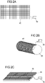
- a magnetic grid 40 is used, as in FIG Figure 2 (A) is shown.
- the magnetic grid is symbolically connected to a control unit 50 in the form of a computer to show that the magnetic grid is controlled via a control unit.
- the magnetic grid 40 is applied to the pressure body.
- the pressure body is a pressure roller 20
- the pressure hull is a pressure plate.
- FIG. 3 (A) shows a section of a structure of a printing form according to the present invention.
- a roller 20, to which a magnetic grid 40 is applied serves as the pressure body.
- Two grid cells 41, 45 of the magnetic grid 40 are shown. These are symbolically linked to a control unit 50 in the form of a computer.
- the cover layer 42 is located above the grid cells 41, 45.
- the cover layer 42 has magnetic particles 43 which are distributed in the cover layer 42.
- FIG. By applying a voltage to the grid cell 45, a magnetic field is created which attracts the magnetic particles in the top layer. As a result, the cover layer is deformed in such a way that a cavity 60 is formed.
- Figure 3 (B) also shows a section of a structure of a printing form according to the present invention.
- a magnetic grid 40 is in turn applied to a roller 20, of which two grid cells 41, 45 are shown.
- the cover layer 42 has areas made of a second material 44 in addition to the magnetic particles 43 .
- the areas made of the second material 44 did not have any magnetic particles and are also not magnetizable according to the invention.
- a voltage By applying a voltage to the grid cell 45, a magnetic field is created which attracts the magnetic particles in the top layer.
- the cover layer is deformed in such a way that a cavity 60 is formed.
- the regions made of the second material 44 in the cover layer are not deformed and contribute to the shaping of the cavity.
- the areas made of the second material 44 serve to stabilize the cover layer by forming webs that support the squeegeeing off after a print medium 100 has been picked up.
- Figure 3 (C) shows a section of a structure of a printing forme according to the present invention, the printing forme having a printing plate 26 as a pressure body.
- the further structure is analogous to Figure 3 (A) .
- figure 4 shows the cover layer 42 in a plan view. A large number of cavities 60 are shown, which in this view have a circular outline.
- Figure 5 (A) shows three different shapes of cavities 60 formed in a cover layer 42.
- FIG. The cover layer 42 is shown in cross section.
- cavities 60 of various shapes can be formed with the present invention. It is therefore possible to adapt the shape of the cavities to the desired application. The present invention thus offers great flexibility when printing on substrates 30.
- Figure 5 (B) illustrates the shape of the cavities 60 when the top layer 42 viewed from above. All cavities 60 have a circular shape in this view.
- Figure 5(C) shows other shapes of cavities listed in the table below.
- the cover layer 42 is shown in cross-section. figure shape of the cavity a pointed pyramid b truncated pyramid c Truncated pyramid with steep flanks i.e pointed cap e normal calotte f U-shape with steep sides and a wide base
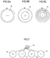
- Figure 6 (A) to (C) represent three different printing forms, each with a roller 20 serves as a pressure body.
- the rollers 20 have different diameters.
- the roller circumference determines the maximum print data length or the repeat that can be printed with, since the cells are fixed to the print body.
- the printing form has a sensor that is suitable for precisely determining a position of the circumference of the roller. With the help of the sensor, it is then possible to determine exactly at which point on the circumference of the roller it is currently printing. That is, after the cavities 60 are printed, they can be rearranged and shaped on the platen.
- the present invention therefore makes it possible to print digital print patterns on printing materials that have a longer print data length than the circumference of the roller.
- this offers the advantage that the circumference of a printing roller can be selected independently of the length of the print data or the length of a repeat of a print pattern. This means that it is no longer necessary to provide rollers with different circumferences in production in order to print print samples with different print data lengths.
- the print data length that can be printed is no longer dependent on the existing rollers. Any length of print data can be printed with one roller with the present invention will. This offers an enormous economic advantage and an enormously increased flexibility compared to conventional gravure printing devices and processes.
- the printing form Figure 6 (C) can map the same print data length in seven circulations as the print form in Figure 6 (B) in two rounds. Both printing forms form the same print data length as the printing form in Figure 6 (A) . After the end of the printing process, in all three cases there are printing materials that have the same print pattern with the same print data length.
- FIG 7 represents an example for the execution of a printing process with the present invention.
- the four printing forms have the rollers 20, 21, 22, 23 as pressure bodies.
- a different print medium is assigned to each roller.
- Digital separation data is created from a digital print pattern by a control device 50 in the form of a computer.
- the digital separation data are then transmitted to the rollers 20, 21, 22, 23 and the cavities on the cover layers of the rollers 20, 21, 22, 23 are formed accordingly.
- the calculation of separation data is based on methods known to those skilled in the art.
- FIG 8 shows an embodiment of the invention with a device for data transmission.
- All grid points on the magnetic grid 40 are networked 70 for data transmission. Some of the grid points are each connected via an intermediate network 71 to a central network with a contact 72 .
- the contact can be a slip ring transmitter, for example.
- a connection to a control unit, for example in the form of a computer 50, can be established via the contact. This arrangement makes it possible to exchange data between the control device and the magnetic grid 40 and thus to control the arrangement of the cavities 60 . Networking takes place via electronic connections such as cables, circuit boards and/or conductor foils.
- a roller 20 is shown in two views as the pressure body.
- FIG 9 represents another embodiment of the invention with a device for data transmission.
- the grid points are networked 70, with an intermediate network 71 leading to a central network with a transmitter/receiver device 73 which is suitable for transmitting data without contact.
- a control device for example in the form of a computer 50, also has a transmitter/receiver device 74 which is suitable for transmitting data in a contactless manner. This arrangement makes it possible to transfer data between the control device and the magnetic grid 40 exchange and thus to control the arrangement of the cavities 60.
- a roller 20 is shown in two views as the pressure body.
- Figure 10 (A) shows an embodiment of the invention with a device for dispensing a print medium 100.
- the print medium 100 is picked up from a container 91 by the roller 20 of the printing form dipping into the container 91 and the cavities 60 on the cover layer 42 are completely flooded with print medium.
- the squeegee 25 then removes the excess printing medium 100, so that there is only printing medium 100 in the cavities 60, but the cover layer between the cavities 60 is free of the printing medium.
- the print medium 100 is transferred to the rubber roller 80 and from there to the printing material 30.
- the control of the printing process is symbolized by a control device in the form of a computer 50.
- Figure 10 (B) shows a further embodiment of the invention with a device for dispensing a print medium 100.
- the print medium 100 is placed on the printing form from above, the printing form comprising a roller 20.
- the excess printing medium 100 is removed by the squeegee 25.
- the print medium 100 is then transferred to the rubber roller 80 and from there to the printing material 30.
- the control of the printing process is symbolized by a control device in the form of a computer 50.
- Figure 13 shows another embodiment of the invention having an apparatus for dispensing a print medium 100 that includes ink ducts 90 within the print hull.
- the ink lines 90 advantageously run through the printing body and the magnetic grid 40 and end in the top layer 42 of the printing form.
- the ink ducts 90 are positioned so that each cavity 60 present on the cover layer 42 can be filled with print medium 100.
- the cavities 60 are filled from the inside of the pressure hull.
- Ink lines 90 are connected to respective reservoirs containing print media 100 .
- the cavities 60 can be filled in a targeted manner using suitable pumping and control devices.
- the containers with the print media 100 and the pumping devices are not shown for the sake of clarity.
- a computer 50 is shown symbolically as the control device.
- the print medium is transferred from the printing form to a rubber roller 80 and from there to the printing material 30.
- Figure 11(B) shows the same structure of a printing form with ink lines 90. In this embodiment, however, the printing material 30 is printed directly from the printing form with the printing medium 100.
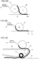
- Figure 12 (A) to (C) shows different transfer paths of the print medium 100 to a printing material 30 in the printing process using the method according to the invention.
- Figure 12 (A) shows an indirect transfer of the printing medium 100 from the printing form via a rubber roller 80 to the printing material 30.
- Figure 12 (B) represents a direct printing method using the method according to the invention.
- the printing medium 100 is transferred directly to the printing material 30 by the printing form.
- Figure 12 (C) shows a printing method with a printing forme that has a roller 20 as a pressure body.
- a print medium 100 is applied to the printing form, and the print medium 100 is applied to a flexible transmission element 83 .
- the flexible transfer element 83 is guided over a deflection roller 81 and then the print pattern is transferred to the printing material 30 .
- the flexible transfer element 83 is pressed against the printing material 100 with a movable counter-pressure roller 82 .
- the movable counter-pressure roller 82 can adapt to the structuring of the printing material 30 in such a way that during the transfer of the printing medium 100 to the printing material 30 there is a sufficiently large contact pressure at all times.
- the contact pressure is sufficiently high if error-free transfer of the print medium 100 is ensured.
- the movable counter-pressure roller 82 additionally has an elastic coating such that the flexible transfer element 83 is pressed at least partially into structures on the surface of the printing material 30, so that error-free transfer of the print medium 100 is ensured.
- figure 13 shows the printing of a printing material 30 with a device according to the invention.
- the device includes a pressure plate 26 as a pressure body.
- An impression roller 95 presses the printing material 30 onto the device according to the invention, so that a transfer of the printing medium 100 to the printing material 30 can take place.
- the digital separation data were transferred from a digital print pattern, which represents a print decor, to four printing forms, with each printing form receiving a separate printing color.
- Each printing form had a roller as the printing element.
- the cavities 60 were formed on the cover layer 42 of the rolls 20, 21, 22, 23 according to the digital separation data.
- the cavities 60 of the rollers 20, 21, 22, 23 were each filled with paint via a container and the top layer 42 was then cleaned with a squeegee 25.
- the colors were printed one after the other directly onto a pre-primed wood-based panel.
- the digital separation data were transferred from a digital print pattern, which represents a print decor, to four printing forms, with each printing form receiving a separate printing color.
- Each printing form had a roller 20, 21, 22, 23 as the printing body.
- the cavities 60 were formed on the cover layer 42 of the rollers 20, 21, 22, 23 in accordance with the digital separation data.
- the cavities 60 of the rollers 20, 21, 22, 23 were each filled with paint via a container and the top layer 42 was then cleaned with a squeegee 25.
- the ink was transferred from the printing form to a rubber roller 80 and printed by it onto a preprimed wood-based panel. All the colors were applied one after the other in this way.
- the digital separation data were transferred from a digital print pattern, which represents a print decor, to four printing forms, with each printing form receiving a separate printing color.
- Each printing form had a plate 26 as the printing body.
- the cavities 60 were filled with ink using an applicator roller and the surface of the cover layer 42 was then cleaned using a squeegee 25 .
- the print pattern was printed directly onto a pre-primed wood-based panel.
- a primer was applied to a print base paper with a weight of 70 g/m 2 and then the print base paper was printed with a digital print pattern in the form of a decoration according to exemplary embodiments 1 and 2 and then further processed as follows:
- the decorated paper layers were impregnated with aqueous melamine resin. After drying, the paper layers were cut and stacked to form a laminate for pressing. Various layers were stacked up to produce a laminate, as described below.
- a resin-impregnated paper layer was first applied as a counteract to the underside of a carrier board, which in this exemplary embodiment was a chipboard.
- the impregnated decorated paper layer was placed on top of the carrier board applied and then a so-called overlay.
- a resin-impregnated transparent paper layer equipped with hard material particles was used as an overlay.
- the stack was moved into a short-cycle press and pressed to form a laminate under the action of heat and pressure.
- a structured press plate was used on the top side in the short-cycle press, so that a structure was created on the surface of the laminate.
- the structure produced is at least partially synchronous with the decor of the paper layer.
- the digital separation data were transferred from a digital print pattern, which represents a print decor, to four printing forms, with each printing form receiving a separate printing color.
- Each printing form had a roller 20, 21, 22, 23 as the printing body.
- the cavities 60 were formed on the cover layer 42 of the rollers 20, 21, 22, 23 in accordance with the digital separation data.
- the cavities 60 of the rollers 20, 21, 22, 23 were each filled with paint via a container and the top layer 42 was then cleaned with a squeegee 25.
- the ink was transferred from the printing form to a flexible transfer element 83 .
- the flexible transmission element 83 was deflected via a deflection roller 81 and then the flexible transmission element 83 was pressed by a movable counter-pressure roller 82 against a structured, pre-primed wooden board. This printing process was carried out sequentially for all colors.
- the pre-primed wood-based panel was thereby provided with the printed decor in such a way that the printed decor is essentially synchronous with the structure of the wood-
- HDF wood-based panels
- a first roller application unit about 70 g melamine resin fl. (solids content: 55% by weight) containing the usual auxiliaries (hardener, wetting agent, etc.) are applied to the board surface.
- a melamine resin is also applied to the underside of the board using the first roller application unit (amount applied: 60 g resin fl./m 2 , solids content: approx. 55% by weight).
- corundum/m 2 (F 200) are sprinkled onto the surface using a scattering apparatus. Thereafter, a melamine resin layer (solids content: 55 wt%) in a Amount of 25 g/m 2 applied. This also contains the usual excipients. A melamine resin is also applied to the underside of the board using a roller application unit (amount applied: 50 g resin fl./m 2 , solids content: approx. 55% by weight). The plate is dried in a circulating air dryer.
- a melamine resin which also contains glass beads, is then applied to the surface of the board. These have a diameter of 60 - 80 ⁇ m. The amount of resin applied is around 20 g melamine resin fl./m 2 (solids content: 61.5% by weight). In addition to the hardener and the wetting agent, the formulation also contains a release agent. The amount of glass beads applied is approx. 3 g/m 2 .
- a melamine resin is also applied to the underside of the board using a roller application unit (amount applied: 40 g resin fl./m 2 , solids content: approx. 55% by weight). The board is again dried in a circulating air dryer and then coated again with a melamine resin containing glass beads.
- cellulose Vivapur 302
- Approx. 20 g melamine resin fl./m 2 solids content: 61.6% by weight
- Approx. 3 g glass beads and 0.25 g cellulose/m 2 are applied again.
- the formulations also contain a release agent.
- a melamine resin is also applied to the underside of the board using a roller application unit (amount applied: 30 g resin fl./m 2 , solids content: approx. 55% by weight).
- the resin is again dried in a circulating air dryer and then the board is pressed in a short-cycle press at 200° C. and a pressure of 400 N/cm 2 .
- the pressing time was 10 seconds.
- a pressed sheet metal with a wooden structure was used as a structuring agent.
- the amount of resin varies per roll application in the range from 5 g/m 2 to about 100 g/m 2 ; the solids content of the resin can also vary in the range from 50% by weight to about 80% by weight.
- the amount of corundum varies between 2 g/m 2 and 30 g/m 2 .
- the additives glass and corundum also vary in their respective amounts.
- the digital separation data were transferred from a digital print pattern, which represents a print decor, to four printing forms, with each printing form receiving a separate printing color.
- Each printing form had a roller 20, 21, 22, 23 as the printing body.
- the cavities 60 were formed on the cover layer 42 of the rollers 20, 21, 22, 23 in accordance with the digital separation data.
- the cavities 60 of the rollers 20, 21, 22, 23 were each filled with paint via a container 81 and the top layer 42 was then cleaned with a squeegee 25.
- the colors were printed one after the other directly onto a pre-primed wood-based panel.
- the circumference of the rollers 20, 21, 22, 23 of the printing forms was 70 cm, but the print data length of the print pattern was 140 cm. Therefore, during the printing process, the position of the cavities 60 of each roller 20, 21, 22, 23, which had already printed, was rearranged immediately after the printing process. The arrangement was made in such a way that the entire print pattern could be printed with two revolutions of the rollers 20, 21, 22, 23.
- An ink or a powder with electrically conductive particles is used as the printing medium.
- a functional layer is applied to the printing material as an electrically conductive form, for which purpose the base bodies are laid out in rows.
- the application quantity of the media is in the range of 3-50g pigment per m 2 .
- the functional layer is then dried and/or cured.
- a powder or fibers are taken up as the pressure medium.
- the cavities form back and release the powder or fibers onto the printing material.
- the printed layer is then dried and/or cured.
- Example 11 printed structure
- a UV varnish is picked up by means of the device according to the invention and applied to a printing material.
- the application of the UV coating is carried out on the printing material at positions where a structural formation is desired, for example in areas where a decoration is shown on the printing material, which, among other things, represents wood pores.
- the structure printed by the device according to the invention is essentially congruent with the pore structure.
- a production material such as corundum or glass is accommodated as a pressure medium by the device according to the invention.
- a precisely defined amount of the pressure medium is taken up, which is determined by the shape of the cavities formed.
- the cavities can be formed with variable shapes and also variable depths, and thus a defined volume. This makes it possible to dose the application quantity of a print medium and to carry out a fully automatic adjustment to recipes for the application quantity of production materials.
Landscapes
- Engineering & Computer Science (AREA)
- Mechanical Engineering (AREA)
- Printing Methods (AREA)
Claims (15)
- Dispositif pour la génération d'une impression sur un matériau d'impression (30), comprenant :- au moins une forme d'impression ;- au moins un dispositif pour la distribution d'un fluide d'impression (100) ;- au moins un dispositif pour la transmission de données ;- au moins un dispositif pour la commande ;caractérisé en ce quela forme d'impression comprend un corps d'impression, une trame magnétique (40) et une couche de recouvrement (42) ;la trame magnétique (40) est appliquée sur la surface du corps d'impression et la couche de recouvrement (42) se trouve au-dessus de la trame magnétique (40), la couche de recouvrement (42) présentant des particules magnétiques (43) ;chaque point de trame de la trame magnétique (40) peut être commandé indépendamment des autres points de trame de la trame magnétique (40) pour la génération d'un champ magnétique ;la couche de recouvrement (42) présente une élasticité et une hauteur permettant de former une pluralité de cavités (60) pour la réception d'un fluide d'impression (100) ; etchaque point de trame de la trame magnétique peut former au moins une cavité (60), par le fait que les particules magnétiques (43) contenues dans la couche de recouvrement(42) sont attirées par le champ magnétique généré au niveau du point de trame respectif.
- Dispositif selon la revendication 1, caractérisé en ce que le corps d'impression est un rouleau d'impression (20, 21, 22, 23) ou une plaque d'impression (26).
- Dispositif selon l'une quelconque des revendications précédentes, caractérisé en ce que l'au moins un dispositif pour la distribution d'un fluide d'impression (100) présente un récipient (91) comprenant une racle (25), un récipient comprenant un rideau d'air, au moins un rouleau applicateur comprenant au moins une racle ou des conduites pour le transport du fluide d'impression (100).
- Dispositif selon l'une quelconque des revendications précédentes, caractérisé en ce que le fluide d'impression (100) présente au moins un liquide contenant des pigments ou au moins un matériau fonctionnel.
- Dispositif selon l'une quelconque des revendications précédentes, caractérisé en ce que l'au moins un dispositif pour la transmission de données présente au moins deux dispositifs émetteurs/récepteurs, qui sont conçus pour transmettre des données sans contact et/ou en ce que le dispositif pour la transmission de données présente au moins un contact.
- Dispositif selon l'une quelconque des revendications précédentes, caractérisé en ce que l'au moins un dispositif pour la commande est un PC (50), une tablette ou un autre appareil de traitement de données.
- Dispositif selon l'une quelconque des revendications précédentes, caractérisé en ce que la couche de recouvrement (42) présente un matériau du groupe comprenant les élastomères, les matériaux intelligents.
- Dispositif selon l'une quelconque des revendications précédentes, caractérisé en ce que des cavités (60) de forme et/ou de profondeur variables sont formées dans la couche de recouvrement (42).
- Procédé pour la génération d'une pluralité de cavités (60) sur une forme d'impression au moyen d'un dispositif selon l'une quelconque des revendications 1 à 8, dans lequel, par l'intermédiaire du dispositif pour la commande, chaque point de trame de la trame magnétique (40) peut être adressé électriquement, indépendamment des autres points de trame de la trame magnétique (40), et agit ainsi sur une pluralité de particules magnétiques (43),
caractérisé en ce queune tension est appliquée à chaque point de trame de la trame magnétique (40), à la position duquel une cavité (60) doit être produite sur la surface de la forme d'impression ;les particules magnétiques (43) dans la couche de recouvrement (42) sont attirées vers la trame magnétique (40) par la tension appliquée, et une cavité (60) est ainsi formée sur la surface de la forme d'impression à cette position. - Procédé selon la revendication 9, caractérisé en ce que la profondeur et donc le volume de la cavité (60) sont déterminés par l'intensité de la tension appliquée au point de trame correspondant de la trame magnétique (40).
- Procédé selon la revendication 9 ou 10, caractérisé en ce que la couche de recouvrement (42) influence le façonnement des cavités (60).
- Procédé selon l'une quelconque des revendications 9 à 10, caractérisé en ce que des cavités (60) d'un diamètre de 0,05 à 0,15 mm, de préférence d'un diamètre de 0,1 mm, sont formées.
- Utilisation du dispositif pour la génération d'une impression selon l'une quelconque des revendications 1 à 8 dans un procédé pour la génération d'impression sur un matériau d'impression (30), le procédé comprenant les étapes suivantes :- la formation de cavités (60) sur la forme d'impression, qui sont appropriées pour représenter un motif d'impression numérique sur un matériau d'impression (30) ;- la réception d'un fluide d'impression (100) par la forme d'impression à partir d'un dispositif pour la distribution d'un fluide d'impression (100) ; et- l'impression directe ou indirecte du matériau d'impression (30) avec le motif d'impression numérique au moyen du dispositif pour la génération d'une impression.
- Procédé pour l'impression d'un matériau d'impression (30) avec un dispositif selon l'une quelconque des revendications 1 à 8 avec un motif d'impression numérique, caractérisé en ce que :des cavités (60) sont formées sur la forme d'impression, qui sont appropriées pour représenter le motif d'impression numérique sur un matériau d'impression (30) ;un fluide d'impression (100) est reçu par la forme d'impression par le biais d'un dispositif pour la distribution d'un fluide d'impression (100) ; etle motif d'impression numérique est imprimé directement ou indirectement sur le matériau d'impression (30) avec le dispositif.
- Procédé selon la revendication 14, caractérisé en ce que le matériau d'impression (30) est choisi dans un groupe contenant le papier, le verre, le métal, les films, les matériaux à base de bois, notamment les panneaux MDF ou HDF, les panneaux WPC, les placages, les couches de vernis, les panneaux en plastique, le plastique renforcé par des fibres, le papier dur et les panneaux de support inorganiques.
Priority Applications (1)
| Application Number | Priority Date | Filing Date | Title |
|---|---|---|---|
| EP20170576.1A EP3900934B1 (fr) | 2020-04-21 | 2020-04-21 | Dispositif de génération d'une impression sur une matière d'impression et procédé de génération d'une pluralité de cavités sur une forme d'impression dotée d'une matrice magnétique |
Applications Claiming Priority (1)
| Application Number | Priority Date | Filing Date | Title |
|---|---|---|---|
| EP20170576.1A EP3900934B1 (fr) | 2020-04-21 | 2020-04-21 | Dispositif de génération d'une impression sur une matière d'impression et procédé de génération d'une pluralité de cavités sur une forme d'impression dotée d'une matrice magnétique |
Publications (2)
| Publication Number | Publication Date |
|---|---|
| EP3900934A1 EP3900934A1 (fr) | 2021-10-27 |
| EP3900934B1 true EP3900934B1 (fr) | 2022-05-18 |
Family
ID=70390856
Family Applications (1)
| Application Number | Title | Priority Date | Filing Date |
|---|---|---|---|
| EP20170576.1A Active EP3900934B1 (fr) | 2020-04-21 | 2020-04-21 | Dispositif de génération d'une impression sur une matière d'impression et procédé de génération d'une pluralité de cavités sur une forme d'impression dotée d'une matrice magnétique |
Country Status (1)
| Country | Link |
|---|---|
| EP (1) | EP3900934B1 (fr) |
Family Cites Families (6)
| Publication number | Priority date | Publication date | Assignee | Title |
|---|---|---|---|---|
| JPS5040617B1 (fr) * | 1970-03-24 | 1975-12-25 | ||
| DE3835091A1 (de) * | 1988-10-14 | 1990-04-19 | Roland Man Druckmasch | Druckform |
| US5129321A (en) * | 1991-07-08 | 1992-07-14 | Rockwell International Corporation | Direct-to-press imaging system for use in lithographic printing |
| ITMI20061227A1 (it) | 2006-06-26 | 2007-12-27 | Dante Frati | Procedimento per stampare superfici di elementi piani a base di legno |
| EP2636531A1 (fr) | 2012-03-06 | 2013-09-11 | Flooring Technologies Ltd. | Procédé d'impression de la surface d'une pièce usinée |
| PL3020565T3 (pl) * | 2014-11-14 | 2017-04-28 | Flooring Technologies Ltd. | Sposób wytwarzania przynajmniej jednego drukowanego dekoru do stosowania w przynajmniej dwóch różnych metodach druku i urządzenie do realizacji tego sposobu |
-
2020
- 2020-04-21 EP EP20170576.1A patent/EP3900934B1/fr active Active
Also Published As
| Publication number | Publication date |
|---|---|
| EP3900934A1 (fr) | 2021-10-27 |
Similar Documents
| Publication | Publication Date | Title |
|---|---|---|
| DE102009044802B4 (de) | Verfahren und Vorrichtung zur Erzeugung einer dreidimensionalen Oberflächenstruktur auf einem Werkstück | |
| EP2148746B1 (fr) | Procédé et dispositif de revêtement d'une pièce plate avec une substance fluide | |
| EP2313281B2 (fr) | Procédé pour produire une surface imprimée sur une pièce plane | |
| EP2860037B1 (fr) | Procédé destiné à adapter des impressions décoratives et dispositif destiné à l'exécution du procédé | |
| EP2927018B1 (fr) | Procédé et dispositif de fabrication des supports de bois fonctionnalisés | |
| EP2861432B1 (fr) | Procédé d'impression de plaques | |
| EP4107001B1 (fr) | Procédé d'adoption des modèles analogiques dans l'impression de décors | |
| EP2847258B1 (fr) | Procédé de fabrication d'une feuille décorative et son utilisation | |
| EP3757178B1 (fr) | Procédé de fabrication d'au moins un matériau porteur pourvu d'un decor imprimé | |
| EP2960064B1 (fr) | Procede de production d'impressions decoratives de qualite identique independamment du procede d'impression utilise et dispositif destine a la realisation de ce procede | |
| EP3020565A1 (fr) | Procédé de création d'au moins un décor imprimé destiné à être utilisé dans au moins deux procédés d'impression distincts et un dispositif d'exécution de ce procédé | |
| EP3470972B1 (fr) | Procédé d'utilisation multiple de données d'impression numérique permettant de fabriquer des décors imprimés de haute qualité optique et/ou haptique sur un matériau de support | |
| EP3928986B1 (fr) | Dispositif de génération d'une impression sur une matière d'impression et procédé de génération d'une pluralité de cavités sur une forme d'impression au moyen des piézoacteurs | |
| EP3059020A1 (fr) | Procédé de fabrication d'une plaque en dérivé de bois, notamment d'une plaque en dérivé de bois dotée d'une couche décorative | |
| EP3865309B1 (fr) | Procédé de fabrication d'au moins un matériau porteur pourvu d'un décor imprimé | |
| EP3900934A1 (fr) | Dispositif de génération d'une impression sur une matière d'impression et procédé de génération d'une pluralité de cavités sur une forme d'impression dotée d'une matrice magnétique | |
| EP3967494A1 (fr) | Dispositif de génération d'une impression sur un support d'impression et procédé de commande du volume de puisage sur une plaque d'impression | |
| EP4384402A1 (fr) | Procédé et dispositif d'application d'une décoration et d'une structure de surface sur un matériau de support | |
| EP3517313B1 (fr) | Modification ultérieure d'une surface décorative | |
| EP4624189A1 (fr) | Procédé et dispositif de fabrication d'un stratifié, en particulier d'un stratifié dans une presse cpl dotée d'une structure synchrone décorative | |
| WO2025257273A1 (fr) | Procédé et dispositif d'impression efficace d'une décoration sur un matériau de support | |
| WO2023242052A1 (fr) | Procédé d'impression d'une décoration sur un matériau de support | |
| EP4046815A1 (fr) | Composition contenant une résine |
Legal Events
| Date | Code | Title | Description |
|---|---|---|---|
| STAA | Information on the status of an ep patent application or granted ep patent |
Free format text: STATUS: EXAMINATION IS IN PROGRESS |
|
| PUAI | Public reference made under article 153(3) epc to a published international application that has entered the european phase |
Free format text: ORIGINAL CODE: 0009012 |
|
| 17P | Request for examination filed |
Effective date: 20201111 |
|
| AK | Designated contracting states |
Kind code of ref document: A1 Designated state(s): AL AT BE BG CH CY CZ DE DK EE ES FI FR GB GR HR HU IE IS IT LI LT LU LV MC MK MT NL NO PL PT RO RS SE SI SK SM TR |
|
| B565 | Issuance of search results under rule 164(2) epc |
Effective date: 20201002 |
|
| GRAP | Despatch of communication of intention to grant a patent |
Free format text: ORIGINAL CODE: EPIDOSNIGR1 |
|
| RIC1 | Information provided on ipc code assigned before grant |
Ipc: B41M 1/10 20060101ALI20211118BHEP Ipc: B41F 9/00 20060101ALI20211118BHEP Ipc: B41F 1/00 20060101AFI20211118BHEP |
|
| STAA | Information on the status of an ep patent application or granted ep patent |
Free format text: STATUS: GRANT OF PATENT IS INTENDED |
|
| INTG | Intention to grant announced |
Effective date: 20211223 |
|
| GRAS | Grant fee paid |
Free format text: ORIGINAL CODE: EPIDOSNIGR3 |
|
| GRAA | (expected) grant |
Free format text: ORIGINAL CODE: 0009210 |
|
| STAA | Information on the status of an ep patent application or granted ep patent |
Free format text: STATUS: THE PATENT HAS BEEN GRANTED |
|
| AK | Designated contracting states |
Kind code of ref document: B1 Designated state(s): AL AT BE BG CH CY CZ DE DK EE ES FI FR GB GR HR HU IE IS IT LI LT LU LV MC MK MT NL NO PL PT RO RS SE SI SK SM TR |
|
| REG | Reference to a national code |
Ref country code: GB Ref legal event code: FG4D Free format text: NOT ENGLISH |
|
| REG | Reference to a national code |
Ref country code: CH Ref legal event code: EP |
|
| REG | Reference to a national code |
Ref country code: IE Ref legal event code: FG4D Free format text: LANGUAGE OF EP DOCUMENT: GERMAN |
|
| REG | Reference to a national code |
Ref country code: DE Ref legal event code: R096 Ref document number: 502020001115 Country of ref document: DE |
|
| REG | Reference to a national code |
Ref country code: AT Ref legal event code: REF Ref document number: 1492936 Country of ref document: AT Kind code of ref document: T Effective date: 20220615 |
|
| REG | Reference to a national code |
Ref country code: LT Ref legal event code: MG9D |
|
| REG | Reference to a national code |
Ref country code: NL Ref legal event code: MP Effective date: 20220518 |
|
| PG25 | Lapsed in a contracting state [announced via postgrant information from national office to epo] |
Ref country code: SE Free format text: LAPSE BECAUSE OF FAILURE TO SUBMIT A TRANSLATION OF THE DESCRIPTION OR TO PAY THE FEE WITHIN THE PRESCRIBED TIME-LIMIT Effective date: 20220518 Ref country code: PT Free format text: LAPSE BECAUSE OF FAILURE TO SUBMIT A TRANSLATION OF THE DESCRIPTION OR TO PAY THE FEE WITHIN THE PRESCRIBED TIME-LIMIT Effective date: 20220919 Ref country code: NO Free format text: LAPSE BECAUSE OF FAILURE TO SUBMIT A TRANSLATION OF THE DESCRIPTION OR TO PAY THE FEE WITHIN THE PRESCRIBED TIME-LIMIT Effective date: 20220818 Ref country code: NL Free format text: LAPSE BECAUSE OF FAILURE TO SUBMIT A TRANSLATION OF THE DESCRIPTION OR TO PAY THE FEE WITHIN THE PRESCRIBED TIME-LIMIT Effective date: 20220518 Ref country code: LT Free format text: LAPSE BECAUSE OF FAILURE TO SUBMIT A TRANSLATION OF THE DESCRIPTION OR TO PAY THE FEE WITHIN THE PRESCRIBED TIME-LIMIT Effective date: 20220518 Ref country code: HR Free format text: LAPSE BECAUSE OF FAILURE TO SUBMIT A TRANSLATION OF THE DESCRIPTION OR TO PAY THE FEE WITHIN THE PRESCRIBED TIME-LIMIT Effective date: 20220518 Ref country code: GR Free format text: LAPSE BECAUSE OF FAILURE TO SUBMIT A TRANSLATION OF THE DESCRIPTION OR TO PAY THE FEE WITHIN THE PRESCRIBED TIME-LIMIT Effective date: 20220819 Ref country code: FI Free format text: LAPSE BECAUSE OF FAILURE TO SUBMIT A TRANSLATION OF THE DESCRIPTION OR TO PAY THE FEE WITHIN THE PRESCRIBED TIME-LIMIT Effective date: 20220518 Ref country code: BG Free format text: LAPSE BECAUSE OF FAILURE TO SUBMIT A TRANSLATION OF THE DESCRIPTION OR TO PAY THE FEE WITHIN THE PRESCRIBED TIME-LIMIT Effective date: 20220818 |
|
| PG25 | Lapsed in a contracting state [announced via postgrant information from national office to epo] |
Ref country code: RS Free format text: LAPSE BECAUSE OF FAILURE TO SUBMIT A TRANSLATION OF THE DESCRIPTION OR TO PAY THE FEE WITHIN THE PRESCRIBED TIME-LIMIT Effective date: 20220518 Ref country code: PL Free format text: LAPSE BECAUSE OF FAILURE TO SUBMIT A TRANSLATION OF THE DESCRIPTION OR TO PAY THE FEE WITHIN THE PRESCRIBED TIME-LIMIT Effective date: 20220518 Ref country code: LV Free format text: LAPSE BECAUSE OF FAILURE TO SUBMIT A TRANSLATION OF THE DESCRIPTION OR TO PAY THE FEE WITHIN THE PRESCRIBED TIME-LIMIT Effective date: 20220518 Ref country code: IS Free format text: LAPSE BECAUSE OF FAILURE TO SUBMIT A TRANSLATION OF THE DESCRIPTION OR TO PAY THE FEE WITHIN THE PRESCRIBED TIME-LIMIT Effective date: 20220918 |
|
| PG25 | Lapsed in a contracting state [announced via postgrant information from national office to epo] |
Ref country code: SM Free format text: LAPSE BECAUSE OF FAILURE TO SUBMIT A TRANSLATION OF THE DESCRIPTION OR TO PAY THE FEE WITHIN THE PRESCRIBED TIME-LIMIT Effective date: 20220518 Ref country code: SK Free format text: LAPSE BECAUSE OF FAILURE TO SUBMIT A TRANSLATION OF THE DESCRIPTION OR TO PAY THE FEE WITHIN THE PRESCRIBED TIME-LIMIT Effective date: 20220518 Ref country code: RO Free format text: LAPSE BECAUSE OF FAILURE TO SUBMIT A TRANSLATION OF THE DESCRIPTION OR TO PAY THE FEE WITHIN THE PRESCRIBED TIME-LIMIT Effective date: 20220518 Ref country code: ES Free format text: LAPSE BECAUSE OF FAILURE TO SUBMIT A TRANSLATION OF THE DESCRIPTION OR TO PAY THE FEE WITHIN THE PRESCRIBED TIME-LIMIT Effective date: 20220518 Ref country code: EE Free format text: LAPSE BECAUSE OF FAILURE TO SUBMIT A TRANSLATION OF THE DESCRIPTION OR TO PAY THE FEE WITHIN THE PRESCRIBED TIME-LIMIT Effective date: 20220518 Ref country code: DK Free format text: LAPSE BECAUSE OF FAILURE TO SUBMIT A TRANSLATION OF THE DESCRIPTION OR TO PAY THE FEE WITHIN THE PRESCRIBED TIME-LIMIT Effective date: 20220518 Ref country code: CZ Free format text: LAPSE BECAUSE OF FAILURE TO SUBMIT A TRANSLATION OF THE DESCRIPTION OR TO PAY THE FEE WITHIN THE PRESCRIBED TIME-LIMIT Effective date: 20220518 |
|
| REG | Reference to a national code |
Ref country code: DE Ref legal event code: R097 Ref document number: 502020001115 Country of ref document: DE |
|
| PLBE | No opposition filed within time limit |
Free format text: ORIGINAL CODE: 0009261 |
|
| STAA | Information on the status of an ep patent application or granted ep patent |
Free format text: STATUS: NO OPPOSITION FILED WITHIN TIME LIMIT |
|
| PG25 | Lapsed in a contracting state [announced via postgrant information from national office to epo] |
Ref country code: AL Free format text: LAPSE BECAUSE OF FAILURE TO SUBMIT A TRANSLATION OF THE DESCRIPTION OR TO PAY THE FEE WITHIN THE PRESCRIBED TIME-LIMIT Effective date: 20220518 |
|
| 26N | No opposition filed |
Effective date: 20230221 |
|
| PG25 | Lapsed in a contracting state [announced via postgrant information from national office to epo] |
Ref country code: LU Free format text: LAPSE BECAUSE OF NON-PAYMENT OF DUE FEES Effective date: 20230421 |
|
| REG | Reference to a national code |
Ref country code: BE Ref legal event code: MM Effective date: 20230430 |
|
| PG25 | Lapsed in a contracting state [announced via postgrant information from national office to epo] |
Ref country code: MC Free format text: LAPSE BECAUSE OF FAILURE TO SUBMIT A TRANSLATION OF THE DESCRIPTION OR TO PAY THE FEE WITHIN THE PRESCRIBED TIME-LIMIT Effective date: 20220518 |
|
| PG25 | Lapsed in a contracting state [announced via postgrant information from national office to epo] |
Ref country code: MC Free format text: LAPSE BECAUSE OF FAILURE TO SUBMIT A TRANSLATION OF THE DESCRIPTION OR TO PAY THE FEE WITHIN THE PRESCRIBED TIME-LIMIT Effective date: 20220518 Ref country code: IT Free format text: LAPSE BECAUSE OF FAILURE TO SUBMIT A TRANSLATION OF THE DESCRIPTION OR TO PAY THE FEE WITHIN THE PRESCRIBED TIME-LIMIT Effective date: 20220518 |
|
| REG | Reference to a national code |
Ref country code: IE Ref legal event code: MM4A |
|
| PG25 | Lapsed in a contracting state [announced via postgrant information from national office to epo] |
Ref country code: BE Free format text: LAPSE BECAUSE OF NON-PAYMENT OF DUE FEES Effective date: 20230430 |
|
| PG25 | Lapsed in a contracting state [announced via postgrant information from national office to epo] |
Ref country code: IE Free format text: LAPSE BECAUSE OF NON-PAYMENT OF DUE FEES Effective date: 20230421 |
|
| PG25 | Lapsed in a contracting state [announced via postgrant information from national office to epo] |
Ref country code: IE Free format text: LAPSE BECAUSE OF NON-PAYMENT OF DUE FEES Effective date: 20230421 |
|
| PG25 | Lapsed in a contracting state [announced via postgrant information from national office to epo] |
Ref country code: BG Free format text: LAPSE BECAUSE OF FAILURE TO SUBMIT A TRANSLATION OF THE DESCRIPTION OR TO PAY THE FEE WITHIN THE PRESCRIBED TIME-LIMIT Effective date: 20220518 |
|
| PG25 | Lapsed in a contracting state [announced via postgrant information from national office to epo] |
Ref country code: BG Free format text: LAPSE BECAUSE OF FAILURE TO SUBMIT A TRANSLATION OF THE DESCRIPTION OR TO PAY THE FEE WITHIN THE PRESCRIBED TIME-LIMIT Effective date: 20220518 |
|
| PGFP | Annual fee paid to national office [announced via postgrant information from national office to epo] |
Ref country code: DE Payment date: 20250402 Year of fee payment: 6 |
|
| PGFP | Annual fee paid to national office [announced via postgrant information from national office to epo] |
Ref country code: FR Payment date: 20250424 Year of fee payment: 6 |
|
| PGFP | Annual fee paid to national office [announced via postgrant information from national office to epo] |
Ref country code: CH Payment date: 20250501 Year of fee payment: 6 |
|
| PGFP | Annual fee paid to national office [announced via postgrant information from national office to epo] |
Ref country code: AT Payment date: 20250721 Year of fee payment: 5 |
|
| PG25 | Lapsed in a contracting state [announced via postgrant information from national office to epo] |
Ref country code: CY Free format text: LAPSE BECAUSE OF FAILURE TO SUBMIT A TRANSLATION OF THE DESCRIPTION OR TO PAY THE FEE WITHIN THE PRESCRIBED TIME-LIMIT; INVALID AB INITIO Effective date: 20200421 |
|
| PG25 | Lapsed in a contracting state [announced via postgrant information from national office to epo] |
Ref country code: HU Free format text: LAPSE BECAUSE OF FAILURE TO SUBMIT A TRANSLATION OF THE DESCRIPTION OR TO PAY THE FEE WITHIN THE PRESCRIBED TIME-LIMIT; INVALID AB INITIO Effective date: 20200421 |
|
| PG25 | Lapsed in a contracting state [announced via postgrant information from national office to epo] |
Ref country code: TR Free format text: LAPSE BECAUSE OF FAILURE TO SUBMIT A TRANSLATION OF THE DESCRIPTION OR TO PAY THE FEE WITHIN THE PRESCRIBED TIME-LIMIT Effective date: 20220518 |
|
| PG25 | Lapsed in a contracting state [announced via postgrant information from national office to epo] |
Ref country code: SI Free format text: LAPSE BECAUSE OF FAILURE TO SUBMIT A TRANSLATION OF THE DESCRIPTION OR TO PAY THE FEE WITHIN THE PRESCRIBED TIME-LIMIT Effective date: 20220518 |
|
| PGFP | Annual fee paid to national office [announced via postgrant information from national office to epo] |
Ref country code: GB Payment date: 20260324 Year of fee payment: 7 |
|
| REG | Reference to a national code |
Ref country code: CH Ref legal event code: U11 Free format text: ST27 STATUS EVENT CODE: U-0-0-U10-U11 (AS PROVIDED BY THE NATIONAL OFFICE) Effective date: 20260501 |