EP3900944A1 - Procédé de marquage au moyen des impulsions laser - Google Patents
Procédé de marquage au moyen des impulsions laser Download PDFInfo
- Publication number
- EP3900944A1 EP3900944A1 EP21169495.5A EP21169495A EP3900944A1 EP 3900944 A1 EP3900944 A1 EP 3900944A1 EP 21169495 A EP21169495 A EP 21169495A EP 3900944 A1 EP3900944 A1 EP 3900944A1
- Authority
- EP
- European Patent Office
- Prior art keywords
- laser
- marking
- layer
- laser beam
- pulse
- Prior art date
- Legal status (The legal status is an assumption and is not a legal conclusion. Google has not performed a legal analysis and makes no representation as to the accuracy of the status listed.)
- Granted
Links
Images




Classifications
-
- B—PERFORMING OPERATIONS; TRANSPORTING
- B42—BOOKBINDING; ALBUMS; FILES; SPECIAL PRINTED MATTER
- B42D—BOOKS; BOOK COVERS; LOOSE LEAVES; PRINTED MATTER CHARACTERISED BY IDENTIFICATION OR SECURITY FEATURES; PRINTED MATTER OF SPECIAL FORMAT OR STYLE NOT OTHERWISE PROVIDED FOR; DEVICES FOR USE THEREWITH AND NOT OTHERWISE PROVIDED FOR; MOVABLE-STRIP WRITING OR READING APPARATUS
- B42D25/00—Information-bearing cards or sheet-like structures characterised by identification or security features; Manufacture thereof
- B42D25/20—Information-bearing cards or sheet-like structures characterised by identification or security features; Manufacture thereof characterised by a particular use or purpose
- B42D25/23—Identity cards
-
- B—PERFORMING OPERATIONS; TRANSPORTING
- B42—BOOKBINDING; ALBUMS; FILES; SPECIAL PRINTED MATTER
- B42D—BOOKS; BOOK COVERS; LOOSE LEAVES; PRINTED MATTER CHARACTERISED BY IDENTIFICATION OR SECURITY FEATURES; PRINTED MATTER OF SPECIAL FORMAT OR STYLE NOT OTHERWISE PROVIDED FOR; DEVICES FOR USE THEREWITH AND NOT OTHERWISE PROVIDED FOR; MOVABLE-STRIP WRITING OR READING APPARATUS
- B42D25/00—Information-bearing cards or sheet-like structures characterised by identification or security features; Manufacture thereof
- B42D25/30—Identification or security features, e.g. for preventing forgery
- B42D25/324—Reliefs
-
- B—PERFORMING OPERATIONS; TRANSPORTING
- B42—BOOKBINDING; ALBUMS; FILES; SPECIAL PRINTED MATTER
- B42D—BOOKS; BOOK COVERS; LOOSE LEAVES; PRINTED MATTER CHARACTERISED BY IDENTIFICATION OR SECURITY FEATURES; PRINTED MATTER OF SPECIAL FORMAT OR STYLE NOT OTHERWISE PROVIDED FOR; DEVICES FOR USE THEREWITH AND NOT OTHERWISE PROVIDED FOR; MOVABLE-STRIP WRITING OR READING APPARATUS
- B42D25/00—Information-bearing cards or sheet-like structures characterised by identification or security features; Manufacture thereof
- B42D25/30—Identification or security features, e.g. for preventing forgery
- B42D25/346—Perforations
-
- B—PERFORMING OPERATIONS; TRANSPORTING
- B42—BOOKBINDING; ALBUMS; FILES; SPECIAL PRINTED MATTER
- B42D—BOOKS; BOOK COVERS; LOOSE LEAVES; PRINTED MATTER CHARACTERISED BY IDENTIFICATION OR SECURITY FEATURES; PRINTED MATTER OF SPECIAL FORMAT OR STYLE NOT OTHERWISE PROVIDED FOR; DEVICES FOR USE THEREWITH AND NOT OTHERWISE PROVIDED FOR; MOVABLE-STRIP WRITING OR READING APPARATUS
- B42D25/00—Information-bearing cards or sheet-like structures characterised by identification or security features; Manufacture thereof
- B42D25/30—Identification or security features, e.g. for preventing forgery
- B42D25/351—Translucent or partly translucent parts, e.g. windows
-
- B—PERFORMING OPERATIONS; TRANSPORTING
- B42—BOOKBINDING; ALBUMS; FILES; SPECIAL PRINTED MATTER
- B42D—BOOKS; BOOK COVERS; LOOSE LEAVES; PRINTED MATTER CHARACTERISED BY IDENTIFICATION OR SECURITY FEATURES; PRINTED MATTER OF SPECIAL FORMAT OR STYLE NOT OTHERWISE PROVIDED FOR; DEVICES FOR USE THEREWITH AND NOT OTHERWISE PROVIDED FOR; MOVABLE-STRIP WRITING OR READING APPARATUS
- B42D25/00—Information-bearing cards or sheet-like structures characterised by identification or security features; Manufacture thereof
- B42D25/40—Manufacture
- B42D25/405—Marking
- B42D25/41—Marking using electromagnetic radiation
-
- B—PERFORMING OPERATIONS; TRANSPORTING
- B42—BOOKBINDING; ALBUMS; FILES; SPECIAL PRINTED MATTER
- B42D—BOOKS; BOOK COVERS; LOOSE LEAVES; PRINTED MATTER CHARACTERISED BY IDENTIFICATION OR SECURITY FEATURES; PRINTED MATTER OF SPECIAL FORMAT OR STYLE NOT OTHERWISE PROVIDED FOR; DEVICES FOR USE THEREWITH AND NOT OTHERWISE PROVIDED FOR; MOVABLE-STRIP WRITING OR READING APPARATUS
- B42D25/00—Information-bearing cards or sheet-like structures characterised by identification or security features; Manufacture thereof
- B42D25/40—Manufacture
- B42D25/405—Marking
- B42D25/43—Marking by removal of material
- B42D25/435—Marking by removal of material using electromagnetic radiation, e.g. laser
-
- B—PERFORMING OPERATIONS; TRANSPORTING
- B42—BOOKBINDING; ALBUMS; FILES; SPECIAL PRINTED MATTER
- B42D—BOOKS; BOOK COVERS; LOOSE LEAVES; PRINTED MATTER CHARACTERISED BY IDENTIFICATION OR SECURITY FEATURES; PRINTED MATTER OF SPECIAL FORMAT OR STYLE NOT OTHERWISE PROVIDED FOR; DEVICES FOR USE THEREWITH AND NOT OTHERWISE PROVIDED FOR; MOVABLE-STRIP WRITING OR READING APPARATUS
- B42D25/00—Information-bearing cards or sheet-like structures characterised by identification or security features; Manufacture thereof
- B42D25/40—Manufacture
- B42D25/45—Associating two or more layers
- B42D25/455—Associating two or more layers using heat
-
- B—PERFORMING OPERATIONS; TRANSPORTING
- B42—BOOKBINDING; ALBUMS; FILES; SPECIAL PRINTED MATTER
- B42D—BOOKS; BOOK COVERS; LOOSE LEAVES; PRINTED MATTER CHARACTERISED BY IDENTIFICATION OR SECURITY FEATURES; PRINTED MATTER OF SPECIAL FORMAT OR STYLE NOT OTHERWISE PROVIDED FOR; DEVICES FOR USE THEREWITH AND NOT OTHERWISE PROVIDED FOR; MOVABLE-STRIP WRITING OR READING APPARATUS
- B42D25/00—Information-bearing cards or sheet-like structures characterised by identification or security features; Manufacture thereof
- B42D25/40—Manufacture
- B42D25/45—Associating two or more layers
- B42D25/46—Associating two or more layers using pressure
-
- B—PERFORMING OPERATIONS; TRANSPORTING
- B42—BOOKBINDING; ALBUMS; FILES; SPECIAL PRINTED MATTER
- B42D—BOOKS; BOOK COVERS; LOOSE LEAVES; PRINTED MATTER CHARACTERISED BY IDENTIFICATION OR SECURITY FEATURES; PRINTED MATTER OF SPECIAL FORMAT OR STYLE NOT OTHERWISE PROVIDED FOR; DEVICES FOR USE THEREWITH AND NOT OTHERWISE PROVIDED FOR; MOVABLE-STRIP WRITING OR READING APPARATUS
- B42D25/00—Information-bearing cards or sheet-like structures characterised by identification or security features; Manufacture thereof
- B42D25/40—Manufacture
- B42D25/48—Controlling the manufacturing process
- B42D25/485—Controlling the manufacturing process by electronic processing means
Definitions
- the invention relates to a method for introducing a marking, which can also contain a contrast and / or surface change through structuring, by means of a laser beam generated by a laser generator, in a layer, the marking having a plurality of pixels in at least one first pixel having connecting web.
- the invention also relates to a marking device, a layer, the use of a layer for a security document and a computer program.
- a security document is usually composed of several layers, which are preferably connected to one another by lamination or lamination.
- the data are introduced under a preferably transparent cover layer within the material. This can be done by laser personalization in the otherwise finished data carrier.
- Another method provides for the data carrier to be provided with a preferably transparent cover layer after the personalization.
- a value or security document can be alienated by removing the cover layer and, after manipulating the underlying data, a new cover layer is applied.
- holograms can be used, such as in the documents WO 2017 109 119 A1 , DE 10 2007 042 386 A1 , EP 2 738 624 B1 and EP 1 475 678 B1 is described.
- a special hologram film is exposed accordingly and applied to the data carrier.
- EP 1 970 211 A1 in writing narrow side surfaces of the document by means of a laser in order to create an optical connection between the layers. If the different layers are separated, the marking applied to the side surfaces will be damaged. Replicating this damaged marking is technically demanding, which makes it difficult to forge the document.
- a security document can be microstructured, which makes manipulation of the cover layer recognizable.
- the end DE 10 2018 106 430 A1 A security element for use as a layer for a security document is known which has a structure which comprises structural elements with dimensions of less than 200 micrometers. Furthermore, a method for producing such a security element is known from the document, the structure being produced by means of laser radiation and / or by local foaming and / or by means of high-resolution 3D printing technology.
- a disadvantage of the known methods for producing microstructures is that the processing time for producing the microstructuring is comparatively long.
- the laser beam is guided to a position on the layer by means of a deflection device with movable deflection mirrors, a laser generator generating the laser beam applying a corresponding number of laser pulses to the layer after positioning. The laser beam is then moved to the next position in the layer at which an image point is to be generated. This process is also known as "Jump and Shoot".
- this includes, for example, a passport, identity card, driver's license, an access control card or another ID card, a vehicle registration document, vehicle registration document, visa , Check, means of payment, in particular a bank note, a check, bank, credit or cash card, customer card, health card, chip card, company ID, proof of eligibility, membership card, gift or shopping voucher, waybill or other proof of authorization, tax code, postage stamp, ticket , To understand (game) tokens or another document.
- a security element can also be, for example, a sticker, adhesive label (for example for article security) or the like, which has the marking generated with the method according to the invention and which is with a preliminary product of a value and / or security document or another article, for example with a product to be marked , the authenticity of which is to be guaranteed, can be inextricably linked in order to form the value and / or security document or this marked article.
- This article can, for example, be a copy from a limited series of similar products, the uniqueness of which is documented by means of a numbering. This numbering can be implemented through the individualization of the security element provided with the security feature.
- the value and / or security product can also be a smart card, for example.
- the value and / or security document can be in ID 1, ID 2, ID 3 or in any other standardized or non-standardized format, for example in booklet form, as in the case of a passport-like object, or for example in card form.
- a valuable and / or security product is generally a laminate made up of several document layers that have been connected to one another over a large area under the action of heat and under increased pressure. These products should meet the standardized requirements, for example in accordance with ISO 10373, ISO / IEC 7810, ISO 14443.
- the product layers consist, for example, of a carrier material that is suitable for lamination.
- the valuable and / or security product and / or the layer can be formed from a polymer selected from a group comprising polycarbonate (PC), in particular bisphenol A polycarbonate, polyethylene terephthalate (PET), their derivatives, such as glycol-modified PET (PETG), polyethylene naphthalate (PEN), polyvinyl chloride (PVC), polyvinyl butyral (PVB), polymethyl methacrylate (PMMA), polyimide (PI), polyvinyl alcohol (PVA), polystyrene (PS), polyvinyl phenol (PVP), polypropylene (PP), Polyethylene (PE), thermoplastic Elastomers (TPE), in particular thermoplastic polyurethane (TPU), acrylonitrile-butadiene-styrene copolymer (ABS) and their derivatives, and / or paper and / or cardboard and / or glass and / or metal and / or ceramic.
- PC polycarbonate
- PET polyethylene terephthalate
- PET
- the valuable and / or security product and / or the layer can also be made from several of these materials, preferably from PC or PC / TPU / PC.
- the polymers can be either filled or unfilled. In the latter case, they are preferably transparent or translucent. If the polymers are filled, they are opaque.
- the value and / or security document is preferably produced from 3 to 12, preferably 4 to 10 layers, at least one of the layers having a marking produced according to the method according to the invention.
- a laminate formed in this way can then be coated on one or both sides with the protective or topcoat or with a film.
- the film can in particular be a volume hologram, a film with a surface hologram (for example a kinegraphic element) or a scratch protection film. Overlay layers formed in this way protect a security feature arranged underneath and / or give the document the required abrasion resistance.
- pattern in the description and in the claims of the present application, this is to be understood as any two-dimensional arrangement of at least one structure or one pixel on a layer.
- a pattern can have any abstract or representational form and consist, for example, of lines, surfaces, also in any combination, or alternatively of characters, such as alphanumeric characters, or reproduce images, for example the photo of the document owner or representations of certain objects. Any other information can also be displayed graphically.
- the object of the present invention is to provide a method which, compared to the prior art, enables a marking to be introduced more quickly and / or more simply, the marking preferably offering greater protection against forgery compared to the prior art.
- the invention achieves the object in a first aspect with a method mentioned at the outset, wherein a movement of the laser beam through the deflection device for guiding the laser beam takes place continuously, and a pulse sequence of two or more to generate one of the image points of the marking during the continuous movement through the deflection device more successive laser pulses of the laser beam is generated.
- the invention makes use of the knowledge that necessary acceleration times, which are required for braking and accelerating the deflection mirrors, can be reduced or avoided if the deflection mirrors of the deflection unit are moved continuously. With a continuous movement of the deflecting mirrors, in contrast to the "jump and shoot principle" described above, no or only slight inertia forces of the deflecting device have to be overcome, whereby a processing speed when introducing the marking can be significantly increased.
- By generating a pulse sequence of two or more laser pulses it is achieved that the laser beam has to be guided less frequently, preferably only once, over the first path connecting the image points.
- processing times can also be shortened which are required for guiding the laser beam several times along the first path connecting the image points.
- the laser beam is preferably guided only once by means of the movable deflection mirror of the deflection device along the first path on the layer that connects the image points.
- the laser beam can, however, preferably also be guided several times along the first path.
- the marking is preferably a security marking.
- the layer is preferably a layer of a valuable and / or security document.
- the method is particularly preferably a method for generating a security marking in a layer for a value and / or security document.
- the pattern generated in this way is preferably an individualized or personalized pattern that contains individualized or personalized information.
- the pattern can match or correspond to an image of the cardholder that is incorporated in a layer below the pattern.
- the laser generator is the device that generates the laser beam.
- the terms laser or laser beam refer to the electromagnetic waves generated by the laser generator.
- a focusing device which focuses the laser beam on and / or into the layer of the material to be processed, is preferably arranged between the deflection device and the layer.
- the focusing device is particularly preferably a flat field focusing device.
- the deflection device preferably guides the focal point of the laser beam along the first path.
- the laser beam when the laser beam is guided along the first path, the laser beam does not have to strike the layer continuously either.
- the laser beam preferably only hits the layer when a laser pulse of the pulse sequence is generated.
- the continuous movement of the deflecting mirrors then leads a theoretical point of incidence of the laser beam, which is preferably the focal point, along the path on and / or into the layer of the material to be processed provided for this purpose.
- the laser pulses are ultrashort laser pulses.
- Ultrashort laser pulses preferably have a pulse duration of less than 10 picoseconds (10 ps), in particular less than 1 ps.
- the ultrashort laser pulses particularly preferably have a pulse duration in a range from 100 femtoseconds (100 fs) to 900 fs, further preferably 100 fs to 800 fs, particularly preferably 200 fs to 600 fs.
- micro- or nano-laser structures can be manufactured comparatively easily with ultra-short laser pulses.
- the use of ultra-short laser pulses enables the precise production of structural elements and / or the efficient generation of pixels.
- ultrashort laser pulses minimize or avoid thermal or mechanical damage to the structural elements during processing. With a suitable choice of the processing parameters, a nearly melt-free and / or carbonization-free processing with high precision is possible.
- the laser pulses are preferably generated with an oscillator frequency, measured between two successive laser pulses of the pulse train, which has a value in a range from 100 kHz to 100 MHz.
- An oscillator frequency of the laser pulses of the pulse train is preferably constant. However, it can also be provided that the oscillator frequency is varied between several laser pulses.
- the oscillator frequency describes a time interval between two successive laser pulses. The higher the oscillator frequency, the shorter the time interval between the successive laser pulses of the pulse train.
- an oscillator frequency range from 100 kHz to 100 MHz there is a time interval between two successive laser pulses of 10 microseconds (10 microseconds) to 10 nanoseconds (10 ns).
- the point of impact at which the focused laser pulses or the focused laser beam strike and / or into the relevant layer of the material to be processed is moved along the path by the movable deflection mirror of the deflection device. Even if the laser beam is moved along the path at a very high speed, the point of impact of two successive laser pulses of the laser beam moves only slightly further due to the oscillator frequency according to the invention.
- a time interval between two successive laser pulses is an oscillator frequency of 50 MHz only 20 ns, whereby the point of impact does not move or is barely perceptible to the human eye. Effects caused by the laser pulses on the layer are perceived as a single pixel of the marking. Due to the preferred oscillator frequency, an image point of a marking can be generated by means of several laser pulses, although the deflection device is moved continuously. It should be understood that with a value of the oscillator frequency in the preferred range, more than two laser pulses can also be used to generate an image point, for example 3, 4, 5 or more. Furthermore, a particularly preferred feature effect can be achieved through the continuous movement of the laser beam.
- the markings produced preferably overlap, as a result of which a special microstructure and / or microscopic shape of the image points can be achieved, which then serves as a special security feature.
- the image point generated by means of the laser pulses can be oval. This ovality can then in turn be used to check the authenticity of the document, since it cannot be generated with conventional methods such as the "jump and shoot” method.
- the laser generator has a laser oscillator and a downstream amplifier, the oscillator frequency coinciding with an oscillation frequency of the laser oscillator.
- the ultrashort laser pulses are generated in the laser oscillator by mode coupling and amplified to the desired line in a subsequent amplifier.
- the laser amplifier can preferably be based on Yb: fiber technology or Yb: InnoSlab technology. The pulses are stretched in time before amplification and compressed in time again after amplification. Disk laser amplifiers are also used.
- a scanning speed at which the laser beam is moved along the first path preferably has a value of 10 m / s or greater.
- the scanning speed is indirectly proportional to the processing time required to generate the marking. An increase in the scanning speed thus results in a reduction in the processing time, as a result of which production costs for the marking or a layer having the marking can be reduced.
- the scanning speed preferably has a value of 10 m / s to 30 m / s. If the laser beam is guided over the layer at a scanning speed of 10 m / s, the point of impact moves about 0.2 micrometers (0.2 ⁇ m) between two successive laser pulses of 20 ns, which corresponds to an oscillator frequency of 50 MHz. along the track.
- a distance between two points of impact of 0.2 ⁇ m is imperceptible to the human eye, so that only a single perceptible pixel is generated.
- more than two laser pulses can also be generated at a scanning speed of 10 m / s or greater.
- image points with displacements of the point of impact of 1 ⁇ m which occur at a scanning speed of 10 m / s and an oscillator frequency of 50 MHz with six laser pulses, are still perceived as a single image point.
- a total energy of the pulse train is distributed essentially uniformly over the laser pulses of the pulse train.
- a uniform distribution of the total energy of the pulse train over the laser pulses enables a particularly simple and inexpensive control of the method.
- the fluence energy density describes the energy of a laser pulse that hits the surface to be processed. Due to the high reproducibility of the individual laser pulses, a particularly uniform marking is preferably generated.
- An energy of a laser pulse of the pulse train preferably has a value of 10 microjoules (10 ⁇ J) or less.
- the total energy which is introduced into a material forming the layer with the pulse sequence influences the marking effect caused by the pulse sequence.
- Successive laser pulses can have a joint effect, particularly at high oscillator frequencies.
- a total energy of a pulse sequence of greater than 10 ⁇ J can carbonize a material forming the layer and / or cause particularly high material removal.
- the pulse sequence preferably has a total energy of 10 ⁇ J to 100 ⁇ J, more preferably 10 ⁇ J to 80 ⁇ J, more preferably 10 ⁇ J to 60 ⁇ J, particularly preferably 20 ⁇ J to 40 ⁇ J.
- a fluence of an impinging laser pulse of the pulse sequence has a value that is less than or equal to ten times the value of a threshold fluence of the material forming the layer.
- the fluence is a measure of the energy input per unit area of the layer.
- the threshold fluence describes that fluence, that is to say that energy per unit area of the layer that has to be applied by means of the laser pulses in order to remove a material forming the layer.
- the higher the fluence of the incident laser pulses the higher the amount of material removed per laser pulse.
- the removal efficiency does not have a linear profile, so that a standardized removal rate, measured as the material removed per energy applied, has a maximum.
- this maximum of the removal efficiency is essentially in a range of five to ten times the value of the threshold fluence, so that with a fluence of the incident laser pulses in the preferred range one particularly efficient marking or material removal can be achieved.
- the fluence preferably has a value in a range from 5 to 10 times the value of the threshold fluence of the material forming the layer.
- a number of the laser pulses of the pulse sequence that is generated to generate the respective image point can be varied.
- a first pulse train can only have two laser pulses, a second pulse train then having three or more laser pulses.
- a perceived strength of the generated marking can preferably be varied by varying the number of laser pulses.
- the intensity of the laser pulses can also be varied. For example, a material removal generated by means of the laser pulses could be increased so that a marking is also more clearly perceptible.
- blackening of the material forming the layer, which is caused by the laser pulses can also be stronger if more laser pulses and / or laser pulses of higher intensity are applied.
- a modulation frequency measured between two successive pulse trains, has a modulation frequency value in a range from 1 kHz to 1 MHz.
- the modulation frequency and the scanning speed determine the distance between adjacent image points, measured along the first path. With the same scanning speed, a higher modulation frequency corresponds to a small spacing between the image points, as a result of which the protection against forgery of the marking can be increased.
- a modulation frequency in the preferred range requires a particularly good combination of protection against forgery and processing time. Furthermore, by increasing the modulation frequency and the scanning speed while the distance between the image points remains the same, the required processing time can be reduced. The distance between successive image points is determined from the quotient of the scanning speed by the modulation frequency.
- pulse trains do not necessarily have to be generated strictly with one modulation frequency, but that two successive pulse trains can also be generated with an integer fraction of the modulation frequency. If, for example, a blank point is to be arranged between two successive visible image points, which is optically invisible or does not differ optically from the material forming the layer, then the pulse trains generating the two visible image points are generated with half the modulation frequency. Furthermore, a time interval between two successive pulse trains can also be completely arbitrary.
- the laser beam is increased by one beam progression value in a period between a first laser pulse and a last laser pulse of the pulse sequence moved in a range from 0.01 ⁇ m to 100 ⁇ m, particularly preferably by a value of 1 ⁇ m, along the first path.
- the beam advance value describes a distance from centers of visible effects caused by the laser pulses.
- a beam advance value in the particularly preferred range cannot be perceived by the human eye, so that particularly precise marking is made possible.
- a marking that is generated with a pulse sequence with a beam advance value in the claimed area can serve as a special security feature.
- the image points are preferably generated by removing material from a material forming the layer, with a laser drilling having a drilling depth being created by removing material.
- the layer can also have several materials.
- the image points are then preferably generated by uniform removal of material from the materials forming the layer. However, it can also be provided that only some of the materials forming the layer are removed and / or that the materials are removed in different amounts.
- the bore depth along a bore axis is preferably measured perpendicular to a surface of the layer. However, it can also be provided that the bore depth is measured transversely to the first path and parallel to a beam direction of the laser beam.
- the laser bore is preferably a blind hole. This means that the laser bore preferably does not extend completely through the layer.
- the material is removed without carbonization.
- a material removal is carbonization-free if a material surrounding the image point is not carbonized. Carbonization describes a blackening of the carbon contained in the material forming the layer. If material is removed without carbonization, it can advantageously be achieved that the marking can only be perceived under certain optical lines of sight. If, for example, the line of sight is parallel to the drilling depth of a laser drilling and the material forming the layer is translucent, the marking cannot be perceived optically or only with great difficulty. If, on the other hand, the line of sight is inclined to the axis of the bore, the marking can be perceived, as a result of which a marking produced in this way can have a particularly high security effect.
- the material is preferably removed by sublimation of the material forming the layer.
- a particularly detailed, exact marking can be achieved.
- by means of sublimation of the material forming the layer particularly small image points can be generated.
- sublimation is particularly suitable for a To avoid carbonization of the material surrounding the image point.
- Sublimation describes an immediate phase transition of the material from the solid phase to the gaseous phase.
- the laser bore has an essentially oval cross section.
- Laser beams generally have an essentially round cross-section, so that conventional laser bores produced by means of such laser beams are also essentially round or cylindrical.
- An oval laser bore can preferably also be shaped like an elongated hole.
- the oval cross-section of the laser bore is preferably generated by moving the laser beam or the point of impact between successive laser pulses of the pulse train.
- the oval cross section is particularly preferably elliptical.
- a short semiaxis of the oval cross section is preferably essentially transverse to the first path of the plurality of image points.
- the oval cross-section can be generated in an advantageous manner by means of suitable control of the oscillator frequency and the scanning speed.
- the laser bore preferably has an aspect ratio, measured as the quotient of the bore depth and a maximum bore diameter, in a range from 0.05 to 5.
- the aspect ratio influences an optical perception that is caused by the laser drilling.
- Laser bores with a high aspect ratio can appear more contrasting than laser bores with a low aspect ratio.
- the drilling depth can have a value of 1 ⁇ m and the drilling diameter a value of 20 ⁇ m, so that the laser drilling has an aspect ratio of 0.05.
- a perceived color intensity of the marking is varied by varying the drilling depth and / or a maximum drilling diameter of the laser drilling.
- the drilling depth can preferably be varied by means of a number of the laser pulses generated to generate the image point.
- a bore diameter of the laser bore can preferably be increased by increasing the pulse duration of the laser pulses and / or the energy of the laser pulses.
- the image points preferably have a dimension transverse to an irradiation direction of the laser beam of 200 ⁇ m or smaller, preferably 100 ⁇ m or smaller, particularly preferably 40 ⁇ m or smaller.
- the structural elements should preferably have larger dimensions than the wavelength of visible light, which is why, for example, structural elements with dimensions larger than 1 ⁇ m can be used.
- the invention achieves the object mentioned at the beginning with a marking device for introducing a marking having a plurality of pixels into a layer, which has a laser generator which is designed to generate a laser beam, a deflection device with at least one movable deflection mirror for guiding the laser beam on the layer, and a control unit which is designed to control the deflection device and the laser generator, wherein the control unit is designed to control the deflection device in such a way that the at least one deflection mirror of the deflection device for guiding the laser beam along a connecting the image points first path executes a continuous movement, and to control the laser generator in such a way that the laser generator for generating an image point of the marking during the movement of the at least one deflection mirror, a pulse sequence of two or more successive lasers pulsing the laser beam, preferably to generate a single pixel, is applied to the layer.
- the laser generator has a laser oscillator and a downstream amplifier, the laser being designed to provide a pulse sequence of laser pulses whose oscillator frequency corresponds to an oscillation frequency of the laser oscillator.
- the deflection device is preferably designed to move the laser beam along a predetermined path at a scanning speed of 10 m / s or more, measured at the focal point of the laser beam or at the point of impact of the laser beam on the layer.
- the marking device preferably forms a marking system with a layer to be marked. It should be understood here that the marking system can also have further components in addition to the marking device and the layer.
- the invention achieves the object mentioned at the beginning by means of a layer with a marking which has a plurality of pixels, which can be produced by a method with the following steps: guiding a laser beam by means of at least one movable deflection mirror of a deflection device along a first path connecting the pixels on the layer, the laser beam moving continuously through the deflection device, and generating a pulse sequence of two or more successive laser pulses of the laser beam during the continuous movement through the deflection device to generate one of the image points of the marking.
- a layer produced by means of the method described preferably has laser bores with a non-circular cross section.
- the invention achieves the object mentioned at the beginning by using a layer according to the third aspect of the invention in a security document.
- the invention solves the object mentioned at the beginning with a computer program comprising commands which cause the marking device according to the second aspect of the invention to execute the method according to the first aspect of the invention when the computer program is executed on a computing unit.
- Figure 1 shows a method 1 for introducing a marking 3 into a layer 5, which is carried out here by a marking device 7.
- the marking device 7 has a laser generator 9 which is designed to generate a laser beam 11.
- the laser beam 11 is emitted by the laser generator 9 and strikes a deflection device 13 of the marking device 7, which here has a first movable mirror 15 and a second movable mirror 17.
- the deflection device 13 is a biaxial deflection device 19 which is designed to direct the laser beam 11 onto the layer 5.
- a focusing device 21 of the marking device 7, which focuses the laser beam on the layer 5, is also arranged between the deflection device 13 and the layer 5.
- the laser generator 9, the deflection device 13 and the focusing device 21 are connected to a control unit 27 which is designed to control the components of the marking device 7. Together with the layer 5, the marking device 7 forms a marking system 200.
- control unit 27 controls the laser generator 9 accordingly, it generates the laser beam 11, which is then deflected onto the layer 5 by means of the deflection device 13.
- the laser beam 11 is focused by the focusing device 21.
- the control unit 27 controls the mirrors 15, 17 in such a way that the laser beam 11 is guided along a path 29 connecting several image points BP of the marking 3.
- the marking has a regular grid of image points BP.
- any other regular and / or irregular patterns of image points BP can also be generated.
- the deflecting mirrors 15, 17 of the deflecting device 13 are moved continuously, whereby acceleration times that are required for accelerating and decelerating the first mirror 15 and the second mirror 17 can be minimized or avoided.
- the control unit 27 controls the laser generator 9 in such a way that it generates a pulse sequence 33 having a plurality of laser pulses 31.
- the laser beam 11 is therefore not generated continuously here, but only when an image point BP of the marking 3 is to be generated.
- a theoretical point of impact 34 of the laser beam 11, which is defined by the respective position of the mirrors 15, 17 at a specific point in time, is guided continuously along the path 29, however.
- a first image point BP1 is generated, for example, by means of the laser pulses 31 when the laser beam 11 is directed by the deflection device 13 onto the in Fig. 1 shown first position P1 is performed. Although the laser beam 11 continues to move when the laser pulses 31 are generated, since the time interval between the laser pulses 31 is very short due to the high oscillator frequency 35, only one image point BP1 is generated in an optically perceptible manner. Sections of the image point BP generated by means of the individual laser pulses 31 of a pulse train 33 preferably overlap.
- a focal point PF of the laser beam 11 preferably lies on a side 23 of the layer 5 facing the focusing device 21. However, it can also be provided that the focal point PF lies in the layer 5 or on a side 25 facing away from the focusing device 21.
- the focusing device 21 is preferably an F-theta objective 37 or has an F-theta objective 37. It should be understood that the focusing device 21 can preferably also have a plurality of lenses and / or objectives.
- the laser generator 9 has a laser oscillator 39 and an amplifier 41.
- the laser oscillator 39 generates seed laser pulses 43, the energy of which is then increased by means of the amplifier 41 and these can then be emitted as laser pulses 31.
- the laser oscillator 39 generates the seed laser pulses 43 with an oscillation frequency 45.
- a coupling device 47 of the laser generator 9 is designed to decouple seed laser pulses 43 and to conduct them to the amplifier 41. It it should be understood that not each of the seed laser pulses 43 is amplified to form a laser pulse 31.
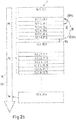
- FIG 2a illustrates the steps of a first conventional method 300 which is designed for generating a marking 3 with a plurality of image points BP.
- a laser beam 11 is guided by means of a deflection device 13 to a first position P1 at which a first image point BP1 is to be generated (step S1.1).
- the deflection mirrors 15, 17 of the deflection device 13 are stopped (step S1.2), so that the focal point FP of the laser beam 11 comes to a standstill.
- several laser pulses 31 are applied one after the other to the layer 5 (steps S1.3 to S1.5).
- the deflection mirrors 15, 17 of the deflection device 13 are accelerated and the laser beam 11 is moved along a path 29 connecting the image points to a second position P2 of a second image point BP2 to be generated (step S1.6).
- the laser beam 11 is stopped again by braking the 15, 17 of the deflection device 13 (step S1.7).
- the second image point BP2 is then generated by applying a plurality of laser pulses 31 to the layer 5 (steps S1.8 to S1.10). This procedure is then continued in an analogous manner until all image points BP of the marking 3 have been generated (step S1.11).
- the movement of the deflection device 13 is thus continuously interrupted within the framework of the known method 300, the many interruptions in the movement increasing the processing time required to generate the marking.
- FIG Figure 2b A first exemplary embodiment of the method according to the invention is now illustrated.
- the laser beam 11 is guided by the deflecting mirrors 15, 17 of the deflecting device 13 along the path 29 connecting the image points BP, but with a continuous movement.
- the continuous guiding of the laser beam 11 through the continuously moving deflection mirrors 15, 17 of the deflection device 13 is shown in FIG Figure 2b illustrated by means of the continuous arrow 49.
- the first position P1 of the first pixel to be generated BP1, the second position P2 of the second pixel to be generated BP2 and the position Pn of the nth pixel to be generated BPn of the marking are shown by way of example on the arrow 49.
- the deflection device 13 guides the laser beam 11 at the scanning speed Vs along the path 29.
- the scanning speed Vs describes the speed at which the point of incidence 34 of the laser beam 11, which is preferably the focal point FP, moves along the path 29 connecting the image points BP will.
- a first pulse sequence 33.1 is generated by the laser generator 9 in the method according to the invention and applied to the layer 5 (step S2.1).
- the pulse train 33 has a total of six laser pulses 31.1, 31.2, 31.3, 31.4, 31.5, 31.6.
- the application of the laser pulses 31.1, 31.2, 31.3, 31.4, 31.5, 31.6 is represented by the substeps S2.1.1, S2.1.2, S2.1.3, S2.1.4, S2.1.5, S2.1.6.
- a pulse train 33 is generated whenever the laser beam 11 reaches a position along the path 29 at which an image point BP is to be generated.
- a first pulse train 33.1 for generating a first pixel BP1, a second pulse train 33.2 for generating a second pixel BP2 (step S2.2) and an nth pulse train 33.n are shown here by way of example (step S2.3).
- the application of the laser pulses 31.7, 31.8, 31.9, 31.10, 31.11, 31.12 of the second pulse train 33.2 is carried out in a manner analogous to the first pulse train 33.1 with the substeps S2.2.1, S2.2.2, S2.2.3, S2.2.4, S2.2.5 , S2.2.6 represents.
- pulse trains 33.3 to 33.n are emitted. After the laser beam 11 has been guided once along the path 29 connecting the image points BP, the marking 3 is completely generated, and the time required to generate the marking 3 can be considerably reduced compared to the conventional method 300.
- the laser pulses 31 of the pulse sequence 33 are generated with a particularly high oscillator frequency 35 of, for example, 50 MHz and applied to the layer 5.
- a particularly high oscillator frequency 35 of, for example, 50 MHz and applied to the layer 5.
- a total period of 100 ns elapses between generating the first laser pulse 31.1 and generating the sixth laser pulse 31.6, which results in a pulse train duration 36 of the first pulse train 33.1 of 100 ns.
- the generation of the pulse train 33 takes place parallel to the arrow 49 or during the movement of the laser beam 11 through the deflection device 13. As by means of the curly brackets in FIG Figure 2b is illustrated, the period of time that is required to generate one of the pulse trains 33 is very much less than a total time required to generate the marking 3.
- the generation of an image point BP can therefore be illustrative as a point on which the laser beam 11 is guided along the Arrow 49 representing path 29 can be made clear.
- a period of time which elapses between the generation of two successive pulse trains 33 is greater than the pulse train duration 36 for generating all of the laser pulses 31 one Pulse train 33.
- the time between successive pulse trains 33 is determined by the modulation frequency 55.
- the modulation frequency 55 has a value of 10 kHz, so that there is a time interval of 100 microseconds between the first pulse train 33.1 and the second pulse train 33.2.
- a time interval between successive pulse trains 33 corresponds to a thousand times the pulse train duration 36 for generating the laser pulses 31 of a single pulse train 33.
- the oscillator frequency preferably has a value in a range from 40 MHz to 50 MHz and the modulation frequency a value of up to 2 MHz, particularly preferably 1.5 MHz to 2 MHz.
- the laser pulses 31 are ultrashort laser pulses 32 with a pulse duration 81 of less than 10 ps ( Figure 7 ). Due to the ultrashort pulse duration of the ultrashort laser pulses 32, the laser beam 11 is only imperceptibly moved along the path 29 during an ultrashort laser pulse 32.
- the oscillator frequency 35 is also so high that a movement of the point of impact 34 of the laser beam 11 along the path 29 between two successive pulses 31.1, 31.2 is only very slight.
- all laser pulses 31.1, 31.2, 31.3, 31.4, 31.5, 31.6 of the first pulse train 33.1 strike the layer 5 at the essentially identical first position P1 along the path 29, and work together to generate the first image point BP1 of the marking 3 .
- respective points of impact 34.1, 34.2, 34.3, 34.4, 34.5, 34.6 of the individual laser pulses 31.1, 31.2, 31.3, 31.4, 31.5, 31.6 of the first pulse train 33.1 are slightly relative to one another are offset and still cooperate to generate the first image point BP1.
- Figure 2c shows that image points BP of the marking 3 can be arranged irregularly with respect to one another.
- the scanning speed Vc at which the laser beam 11 is guided by the deflection device 13 along the path 29 is preferably constant. Possible positions P1 to Pn for generating image points are then at a regular distance from one another. In this exemplary embodiment, the scanning speed Vc has a value of 10 m / s, so that two successive positions P1, P2 have a spatial distance of 1 mm along the path 29 at a modulation frequency 55 of, for example, 10 kHz.
- a pulse train 33 is generated whenever the laser beam 11 reaches a position P.
- a pulse train 33 is not generated at each of the positions P. This is how in Figure 2c a respective pulse sequence 33.1, 33.2, 33.5, 33.7 is generated only at the first position P1, at the second position P2, at a fifth position P5 and at a seventh position P7.
- the means of the pulse trains 33.1, 33.2, 33.5, 33.7 The generated image points BP1, BP2, BP5, BP7 of the marking 3 are shown parallel to the arrow 49.
- the pulse trains 33 can therefore preferably also be generated with an integer fraction of the modulation frequency 55.
- the generation of the pulse trains 33 with an integer multiple of the interval 56 or an integer fraction of the modulation frequency 55 enables a particularly simple method management.
- two successive pulse trains 33 are at any distance from one another.
- markings 3 with particularly individual patterns can be generated.
- Figure 3 illustrates a marking 3 which is produced by removing material from a material 57 forming the layer 5.
- the material is removed by means of sublimation of the material 57 forming the layer 5, a material 59 surrounding the image point BP being free of carbonization. Polymer molecules contained in the surrounding material 59 are not charred.
- a first laser pulse 31.1 of the pulse sequence 33 hits the material 57 of the layer 5, a laser bore 61 being produced.
- the laser bore 61 extends essentially uniformly around the point of impact 34.1 of the first laser pulse, which is arranged at the tip of the arrow illustrating the first laser pulse 31.1.
- a second laser pulse 31.2 of the pulse sequence 33 hits the material 57.
- a further part of the material 57 of the layer 5 is sublimed and thus removed, with a bore depth T1 of the laser bore 61 increasing.
- the laser beam 11 was moved slightly along the path 29 so that a second point of impact 34.2 of the second laser pulse 31.2 is shifted slightly along the path 29 to the first point of impact 34.1 of the first laser pulse 31.1.
- the path 29, which connects the image points BP thus runs to the right.
- material is removed by means of the further laser pulses 31.3, 31.4, 31.5, 31.6 ( Figures 3c to 3f ), the respective points of impact 34.3, 34.4, 34.5, 34.6 being offset from one another.
- the hole depth T1 of the laser hole 61 increases with each impinging laser pulse 31.
- the creation of the laser bore 61 is completed.
- the aspect ratio of the finished laser bore 61 is determined from a quotient T1 / D of the bore depth T1 and a maximum diameter D of the laser bore 61.
- the laser bore Due to the movement of the laser beam 11 along the path 29, the laser bore also has the in Figure 3 stepped profile shown.
- the graduated profile is, however, barely or not perceptible, depending on the characteristics.
- Figure 4 illustrates the method for generating the laser bore 61 in a view directed parallel to the bore depth T1.
- the first laser pulse 31.1 strikes the layer 5 at the first point of impact 34.1 and vaporizes the material 57 forming the layer 5.
- the approximately circular laser bore 61 is thereby produced.
- the second laser pulse 31.2 is then generated and strikes the layer 5 at the second impingement point 34.2, the bore depth T1 increasing.
- the movement of the point of impact 34 can be seen particularly well.
- Figures 4c to 4e illustrate the changing shape of the laser bore 61 due to the impingement of the further laser pulses 31.3, 31.4, 31.5 at the impingement points 34.3, 34.4, 34.5.
- Figure 4f shows the cross section of the laser bore 61 after the material 57 of the layer 5 has also been removed by the impact of the sixth laser pulse 31.6 of the pulse sequence 33.
- the laser bore 61 is thus in Figure 4f completed and has an oval cross-section, which here corresponds to the shape of an elongated hole.
- a short semiaxis 63 of the laser bore 61 is transverse to the path 29 due to the displacement of the point of impact 34.
- a shape of the oval cross section of the laser bore 61 is determined by a scanning speed Vs at which the laser beam 11 is guided by the deflection device 13 along the path 29, the oscillator frequency 35 and the pulse train duration 36 of the laser pulses 31 of a pulse train 33 influenced.
- a marking 3 with laser bores 61, which were produced with the method 1 according to the invention, is therefore particularly forgery-proof.
- the oscillator frequency 35, the pulse train duration 36 of the laser pulses 31 and the scanning speed Vc are selected such that the laser bore 61 has an essentially round cross-section.
- the laser bore 61 can also have an elliptical cross section.
- a cross-sectional shape of the laser bore 61 can preferably be varied by varying a beam cross-section of the laser beam 11.
- a section of a document body of a security document 65 is shown by way of example and not to scale.
- the security document 65 has a front side 67 and a rear side 69.
- the security document 65 is made up of several Layers 71 and comprises a preferably transparent cover layer 73, which here is layer 5 (see FIG Fig. 1 ) is. At least one of the layers 71 and / or 73 can be designed as a film.
- the layers are connected to one another by lamination to form a document body.
- a marking 3 is arranged on the front side 67 of the security document 65, which when viewed perpendicular to the front side 67 is essentially not visible and thus the information underneath remains easily recognizable.
- One or more further layers can also be applied to protect the marking 3.
- the marking 3 When viewed at a glancing angle, i.e. at a flat angle, the marking 3 becomes visible as a matted surface.
- the marking 3 is preferably introduced with an exact fit to an underlying image element 77.
- the marking 3 preferably corresponds to the information below, preferably the image element 77.
- the marking 3 is therefore preferably an individual or personalized marking 3 and carries or encodes individual or personalized information that corresponds to the information of the layer below. A manipulation of the surface or an exchange of the cover layer 73 would thereby be easily recognizable.
- the marking 3 does not have to be arranged over, in particular congruently over, the image element 77, but can also be introduced at another point on the security document 65.
- the layer 5 provided with the marking 3 can also be applied to the rear side 69 of the security document 65.
- Figure 6 shows a section of a layer 5 provided with a marking 3.
- the marking 3 has a pattern of image points BP, which are designed as laser bores 61.
- the method 1 further optionally comprises one of the steps: filling the laser bores with a material that differs from the material forming the layer 5 and / or covering the marking 3 by means of a layer, a foil and / or a film.
- the laser bores 61 can be covered by means of a layer of lacquer.
- Figure 7 illustrates an intensity of a pulse train 33 with three ultrashort laser pulses 32, which are applied to the layer 5 in the inventive method 1 for producing a marking 3, in comparison to a standard pulse 79 as this can be used in a conventional method 300.
- the abscissa of the coordinate system shown describes a time axis ZA, while the ordinate represents a value of the intensity I.
- an intensity IKP of the ultrashort laser pulses 32.1, 32.2, 32.3 corresponds to approximately one third of the intensity IS of the standard pulse 79 the intensity IS of a standard pulse 79.
- a pulse duration 81 of the ultrashort laser pulses 32 and of the standard pulse 79 and the modulation frequency 55 are also identical in this exemplary embodiment.
- Focus point FP intensity I. Intensity of ultrashort laser pulses ICP Standard pulse intensity IS Positions of the pixels P1, P2, P3, P4, P5, P6, P7, P8, Pn steps S # Depth of the laser hole T1 Scanning speed Vs Timeline ZA
Landscapes
- Engineering & Computer Science (AREA)
- Manufacturing & Machinery (AREA)
- Physics & Mathematics (AREA)
- Health & Medical Sciences (AREA)
- Electromagnetism (AREA)
- General Health & Medical Sciences (AREA)
- Toxicology (AREA)
- Optics & Photonics (AREA)
- Laser Beam Processing (AREA)
- Thermal Transfer Or Thermal Recording In General (AREA)
Applications Claiming Priority (1)
| Application Number | Priority Date | Filing Date | Title |
|---|---|---|---|
| DE102020111140.1A DE102020111140A1 (de) | 2020-04-23 | 2020-04-23 | Verfahren zum Markieren mittels Laserpulsen |
Publications (2)
| Publication Number | Publication Date |
|---|---|
| EP3900944A1 true EP3900944A1 (fr) | 2021-10-27 |
| EP3900944B1 EP3900944B1 (fr) | 2025-01-29 |
Family
ID=75625403
Family Applications (1)
| Application Number | Title | Priority Date | Filing Date |
|---|---|---|---|
| EP21169495.5A Active EP3900944B1 (fr) | 2020-04-23 | 2021-04-20 | Procédé de marquage au moyen des impulsions laser |
Country Status (2)
| Country | Link |
|---|---|
| EP (1) | EP3900944B1 (fr) |
| DE (1) | DE102020111140A1 (fr) |
Cited By (2)
| Publication number | Priority date | Publication date | Assignee | Title |
|---|---|---|---|---|
| EP4223548A1 (fr) * | 2021-12-29 | 2023-08-09 | Polska Wytwornia Papierow Wartosciowych S.A. | Procédé de fabrication d'un support papier marqué avec un filigrane et support papier de sécurité marqué, en particulier un papier de sécurité |
| CN119870722A (zh) * | 2025-02-19 | 2025-04-25 | 聊城市科猿激光设备有限公司 | 一种一体式自动化激光雕刻机及方法 |
Families Citing this family (1)
| Publication number | Priority date | Publication date | Assignee | Title |
|---|---|---|---|---|
| DE102024124813A1 (de) * | 2024-08-30 | 2026-03-05 | Giesecke+Devrient ePayments GmbH | Verfahren zum Herstellen eines Sicherheitselementes und selbiges sowie Herstellungsvorrichtung zum Herstellen eines Sicherheitselementes |
Citations (9)
| Publication number | Priority date | Publication date | Assignee | Title |
|---|---|---|---|---|
| EP1970211A1 (fr) | 2007-03-12 | 2008-09-17 | Gemalto Oy | Document d'identification sécurisée et son procédé de fabrication |
| DE102007042386A1 (de) | 2007-09-04 | 2009-03-05 | Bundesdruckerei Gmbh | Verfahren und Vorrichtung zur individuellen farbigen holografischen Belichtung |
| EP1475678B1 (fr) | 2002-02-13 | 2012-01-11 | Japan Science and Technology Agency | Procede de production d'un hologramme a l'aide d'un laser picoseconde |
| WO2013017738A1 (fr) * | 2011-08-03 | 2013-02-07 | Upm-Kymmene Corporation | Procédé et appareil de marquage d'un produit |
| WO2014106517A1 (fr) * | 2013-01-04 | 2014-07-10 | Giesecke & Devrient Gmbh | Procédé de réalisation d'un élément de sécurité comprenant une couche d'enregistrement sensible au rayonnement laser |
| EP2738624B1 (fr) | 2007-10-31 | 2017-04-05 | Bundesdruckerei GmbH | Hologramme et document de sécurité avec échantillons de couleurs de différentes couleurs spectrales |
| WO2017109119A1 (fr) | 2015-12-22 | 2017-06-29 | Bundesdruckerei Gmbh | Procédé d'intégration d'un hologramme dans un corps de document de sécurité et corps de document de sécurité |
| US10391586B1 (en) * | 2015-03-11 | 2019-08-27 | Coherent, Inc. | Method for laser-marking of anodized aluminum |
| DE102018106430A1 (de) | 2018-03-20 | 2019-09-26 | Bundesdruckerei Gmbh | Sicherheitselement mit Mikro- oder Nanostrukturierung |
Family Cites Families (2)
| Publication number | Priority date | Publication date | Assignee | Title |
|---|---|---|---|---|
| US20170189992A1 (en) | 2015-12-31 | 2017-07-06 | Nlight, Inc. | Black sub-anodized marking using picosecond bursts |
| DE102018221365A1 (de) | 2018-12-10 | 2020-06-10 | Trumpf Laser Gmbh | Verfahren zum Abtragen von Material von einem Werkstück und Laserbearbeitungsanlage |
-
2020
- 2020-04-23 DE DE102020111140.1A patent/DE102020111140A1/de active Pending
-
2021
- 2021-04-20 EP EP21169495.5A patent/EP3900944B1/fr active Active
Patent Citations (10)
| Publication number | Priority date | Publication date | Assignee | Title |
|---|---|---|---|---|
| EP1475678B1 (fr) | 2002-02-13 | 2012-01-11 | Japan Science and Technology Agency | Procede de production d'un hologramme a l'aide d'un laser picoseconde |
| EP1970211A1 (fr) | 2007-03-12 | 2008-09-17 | Gemalto Oy | Document d'identification sécurisée et son procédé de fabrication |
| DE102007042386A1 (de) | 2007-09-04 | 2009-03-05 | Bundesdruckerei Gmbh | Verfahren und Vorrichtung zur individuellen farbigen holografischen Belichtung |
| EP2738624B1 (fr) | 2007-10-31 | 2017-04-05 | Bundesdruckerei GmbH | Hologramme et document de sécurité avec échantillons de couleurs de différentes couleurs spectrales |
| WO2013017738A1 (fr) * | 2011-08-03 | 2013-02-07 | Upm-Kymmene Corporation | Procédé et appareil de marquage d'un produit |
| WO2014106517A1 (fr) * | 2013-01-04 | 2014-07-10 | Giesecke & Devrient Gmbh | Procédé de réalisation d'un élément de sécurité comprenant une couche d'enregistrement sensible au rayonnement laser |
| US10391586B1 (en) * | 2015-03-11 | 2019-08-27 | Coherent, Inc. | Method for laser-marking of anodized aluminum |
| WO2017109119A1 (fr) | 2015-12-22 | 2017-06-29 | Bundesdruckerei Gmbh | Procédé d'intégration d'un hologramme dans un corps de document de sécurité et corps de document de sécurité |
| DE102018106430A1 (de) | 2018-03-20 | 2019-09-26 | Bundesdruckerei Gmbh | Sicherheitselement mit Mikro- oder Nanostrukturierung |
| EP3552837A1 (fr) * | 2018-03-20 | 2019-10-16 | Bundesdruckerei GmbH | Élément de sécurité à micro ou nanostructuration |
Cited By (2)
| Publication number | Priority date | Publication date | Assignee | Title |
|---|---|---|---|---|
| EP4223548A1 (fr) * | 2021-12-29 | 2023-08-09 | Polska Wytwornia Papierow Wartosciowych S.A. | Procédé de fabrication d'un support papier marqué avec un filigrane et support papier de sécurité marqué, en particulier un papier de sécurité |
| CN119870722A (zh) * | 2025-02-19 | 2025-04-25 | 聊城市科猿激光设备有限公司 | 一种一体式自动化激光雕刻机及方法 |
Also Published As
| Publication number | Publication date |
|---|---|
| EP3900944B1 (fr) | 2025-01-29 |
| DE102020111140A1 (de) | 2021-10-28 |
Similar Documents
| Publication | Publication Date | Title |
|---|---|---|
| EP1525102B1 (fr) | Document de valeur | |
| EP3900944B1 (fr) | Procédé de marquage au moyen des impulsions laser | |
| EP0330738A1 (fr) | Document | |
| EP3552837B1 (fr) | Élément de sécurité à micro ou nanostructuration | |
| EP3554846B1 (fr) | Procédé permettant de fabriquer un élément de sécurité doté d'une image lenticulaire | |
| EP2941355B1 (fr) | Procédé de réalisation d'un élément de sécurité comprenant une couche d'enregistrement sensible au rayonnement laser | |
| EP3015279B1 (fr) | Procédé de fabrication d'un élément de sécurité comprenant une image lenticulaire | |
| DE102008028705B4 (de) | Verfahren zum Herstellen eines Wert- und/oder Sicherheitsdokuments sowie Wert- und/oder Sicherheitsdokument mit einer demetallisierten Struktur | |
| WO2015149939A1 (fr) | Élément de sécurité muni d'une image lenticulaire | |
| DE19537177C2 (de) | Verfahren zur Herstellung einer Kunststoffkarte in Form einer Ausweiskarte, Telefonkarte, Kreditkarte, Krankenversichertenkarte o. dgl. | |
| DE102005003958A1 (de) | Sicherheitselement und Verfahren zu seiner Herstellung | |
| DE102021121813B4 (de) | Verfahren zum Herstellen eines Identifikations- oder Sicherheitsprodukts mit mindestens einer taktil erfassbaren Erhebung | |
| DE4131617C2 (fr) | ||
| DE19646331C2 (de) | Verfahren zur lokalen plastischen Verformung durch einen Laser | |
| EP3738786A1 (fr) | Élément de sécurité luminescent | |
| EP4049854B1 (fr) | Procédé et dispositif d'application d'une caractéristique de sécurité gravée au laser | |
| EP3972852A1 (fr) | Élément de sécurité comprenant une image anamorphique | |
| EP1493595A2 (fr) | Procédé et dispositif destiné à la production d'une image 3D simulée sur un substrat mince | |
| DE29807638U1 (de) | Prägefolie mit individualisiert gekennzeichneten Sicherheitsmerkmalen | |
| EP4015229B1 (fr) | Produit de valeur ou de sécurité, ainsi que son procédé de fabrication | |
| EP4368409B1 (fr) | Élément de sécurité, document de sécurité et procédé de fabrication d'un document de sécurité | |
| EP2539155B9 (fr) | Dispositif de marquage et procédé de marquage haute résolution de documents de valeur ou de sécurité | |
| EP2644406A2 (fr) | Procédé de fabrication d'un support de données et support de données ainsi obtenu | |
| EP4620697A1 (fr) | Plaque de masquage, ensemble et procédé de génération d'au moins un élément de grille d'une grille sur ou dans un substrat, détectable tactilement | |
| EP3072703B1 (fr) | Procede de fabrication d'une fenetre dans un substrat de papier comprenant un element de securite |
Legal Events
| Date | Code | Title | Description |
|---|---|---|---|
| PUAI | Public reference made under article 153(3) epc to a published international application that has entered the european phase |
Free format text: ORIGINAL CODE: 0009012 |
|
| STAA | Information on the status of an ep patent application or granted ep patent |
Free format text: STATUS: REQUEST FOR EXAMINATION WAS MADE |
|
| 17P | Request for examination filed |
Effective date: 20210504 |
|
| AK | Designated contracting states |
Kind code of ref document: A1 Designated state(s): AL AT BE BG CH CY CZ DE DK EE ES FI FR GB GR HR HU IE IS IT LI LT LU LV MC MK MT NL NO PL PT RO RS SE SI SK SM TR |
|
| B565 | Issuance of search results under rule 164(2) epc |
Effective date: 20210928 |
|
| RBV | Designated contracting states (corrected) |
Designated state(s): AL AT BE BG CH CY CZ DE DK EE ES FI FR GB GR HR HU IE IS IT LI LT LU LV MC MK MT NL NO PL PT RO RS SE SI SK SM TR |
|
| P01 | Opt-out of the competence of the unified patent court (upc) registered |
Effective date: 20230526 |
|
| GRAP | Despatch of communication of intention to grant a patent |
Free format text: ORIGINAL CODE: EPIDOSNIGR1 |
|
| STAA | Information on the status of an ep patent application or granted ep patent |
Free format text: STATUS: GRANT OF PATENT IS INTENDED |
|
| INTG | Intention to grant announced |
Effective date: 20240828 |
|
| GRAS | Grant fee paid |
Free format text: ORIGINAL CODE: EPIDOSNIGR3 |
|
| GRAA | (expected) grant |
Free format text: ORIGINAL CODE: 0009210 |
|
| STAA | Information on the status of an ep patent application or granted ep patent |
Free format text: STATUS: THE PATENT HAS BEEN GRANTED |
|
| AK | Designated contracting states |
Kind code of ref document: B1 Designated state(s): AL AT BE BG CH CY CZ DE DK EE ES FI FR GB GR HR HU IE IS IT LI LT LU LV MC MK MT NL NO PL PT RO RS SE SI SK SM TR |
|
| REG | Reference to a national code |
Ref country code: GB Ref legal event code: FG4D Free format text: NOT ENGLISH |
|
| REG | Reference to a national code |
Ref country code: CH Ref legal event code: EP |
|
| REG | Reference to a national code |
Ref country code: DE Ref legal event code: R096 Ref document number: 502021006486 Country of ref document: DE |
|
| REG | Reference to a national code |
Ref country code: IE Ref legal event code: FG4D Free format text: LANGUAGE OF EP DOCUMENT: GERMAN |
|
| REG | Reference to a national code |
Ref country code: NL Ref legal event code: MP Effective date: 20250129 |
|
| PG25 | Lapsed in a contracting state [announced via postgrant information from national office to epo] |
Ref country code: NL Free format text: LAPSE BECAUSE OF FAILURE TO SUBMIT A TRANSLATION OF THE DESCRIPTION OR TO PAY THE FEE WITHIN THE PRESCRIBED TIME-LIMIT Effective date: 20250129 |
|
| PG25 | Lapsed in a contracting state [announced via postgrant information from national office to epo] |
Ref country code: RS Free format text: LAPSE BECAUSE OF FAILURE TO SUBMIT A TRANSLATION OF THE DESCRIPTION OR TO PAY THE FEE WITHIN THE PRESCRIBED TIME-LIMIT Effective date: 20250429 |
|
| PG25 | Lapsed in a contracting state [announced via postgrant information from national office to epo] |
Ref country code: FI Free format text: LAPSE BECAUSE OF FAILURE TO SUBMIT A TRANSLATION OF THE DESCRIPTION OR TO PAY THE FEE WITHIN THE PRESCRIBED TIME-LIMIT Effective date: 20250129 |
|
| PG25 | Lapsed in a contracting state [announced via postgrant information from national office to epo] |
Ref country code: PL Free format text: LAPSE BECAUSE OF FAILURE TO SUBMIT A TRANSLATION OF THE DESCRIPTION OR TO PAY THE FEE WITHIN THE PRESCRIBED TIME-LIMIT Effective date: 20250129 |
|
| PGFP | Annual fee paid to national office [announced via postgrant information from national office to epo] |
Ref country code: DE Payment date: 20250417 Year of fee payment: 5 |
|
| PG25 | Lapsed in a contracting state [announced via postgrant information from national office to epo] |
Ref country code: ES Free format text: LAPSE BECAUSE OF FAILURE TO SUBMIT A TRANSLATION OF THE DESCRIPTION OR TO PAY THE FEE WITHIN THE PRESCRIBED TIME-LIMIT Effective date: 20250129 |
|
| REG | Reference to a national code |
Ref country code: LT Ref legal event code: MG9D |
|
| PG25 | Lapsed in a contracting state [announced via postgrant information from national office to epo] |
Ref country code: NO Free format text: LAPSE BECAUSE OF FAILURE TO SUBMIT A TRANSLATION OF THE DESCRIPTION OR TO PAY THE FEE WITHIN THE PRESCRIBED TIME-LIMIT Effective date: 20250429 Ref country code: IS Free format text: LAPSE BECAUSE OF FAILURE TO SUBMIT A TRANSLATION OF THE DESCRIPTION OR TO PAY THE FEE WITHIN THE PRESCRIBED TIME-LIMIT Effective date: 20250529 |
|
| PG25 | Lapsed in a contracting state [announced via postgrant information from national office to epo] |
Ref country code: HR Free format text: LAPSE BECAUSE OF FAILURE TO SUBMIT A TRANSLATION OF THE DESCRIPTION OR TO PAY THE FEE WITHIN THE PRESCRIBED TIME-LIMIT Effective date: 20250129 |
|
| PG25 | Lapsed in a contracting state [announced via postgrant information from national office to epo] |
Ref country code: LV Free format text: LAPSE BECAUSE OF FAILURE TO SUBMIT A TRANSLATION OF THE DESCRIPTION OR TO PAY THE FEE WITHIN THE PRESCRIBED TIME-LIMIT Effective date: 20250129 Ref country code: PT Free format text: LAPSE BECAUSE OF FAILURE TO SUBMIT A TRANSLATION OF THE DESCRIPTION OR TO PAY THE FEE WITHIN THE PRESCRIBED TIME-LIMIT Effective date: 20250529 |
|
| PGFP | Annual fee paid to national office [announced via postgrant information from national office to epo] |
Ref country code: FR Payment date: 20250422 Year of fee payment: 5 |
|
| PG25 | Lapsed in a contracting state [announced via postgrant information from national office to epo] |
Ref country code: GR Free format text: LAPSE BECAUSE OF FAILURE TO SUBMIT A TRANSLATION OF THE DESCRIPTION OR TO PAY THE FEE WITHIN THE PRESCRIBED TIME-LIMIT Effective date: 20250430 Ref country code: BG Free format text: LAPSE BECAUSE OF FAILURE TO SUBMIT A TRANSLATION OF THE DESCRIPTION OR TO PAY THE FEE WITHIN THE PRESCRIBED TIME-LIMIT Effective date: 20250129 |
|
| PGFP | Annual fee paid to national office [announced via postgrant information from national office to epo] |
Ref country code: AT Payment date: 20250721 Year of fee payment: 5 |
|
| PG25 | Lapsed in a contracting state [announced via postgrant information from national office to epo] |
Ref country code: SE Free format text: LAPSE BECAUSE OF FAILURE TO SUBMIT A TRANSLATION OF THE DESCRIPTION OR TO PAY THE FEE WITHIN THE PRESCRIBED TIME-LIMIT Effective date: 20250129 |
|
| PG25 | Lapsed in a contracting state [announced via postgrant information from national office to epo] |
Ref country code: SM Free format text: LAPSE BECAUSE OF FAILURE TO SUBMIT A TRANSLATION OF THE DESCRIPTION OR TO PAY THE FEE WITHIN THE PRESCRIBED TIME-LIMIT Effective date: 20250129 |
|
| PG25 | Lapsed in a contracting state [announced via postgrant information from national office to epo] |
Ref country code: DK Free format text: LAPSE BECAUSE OF FAILURE TO SUBMIT A TRANSLATION OF THE DESCRIPTION OR TO PAY THE FEE WITHIN THE PRESCRIBED TIME-LIMIT Effective date: 20250129 |
|
| PG25 | Lapsed in a contracting state [announced via postgrant information from national office to epo] |
Ref country code: IT Free format text: LAPSE BECAUSE OF FAILURE TO SUBMIT A TRANSLATION OF THE DESCRIPTION OR TO PAY THE FEE WITHIN THE PRESCRIBED TIME-LIMIT Effective date: 20250129 |
|
| PG25 | Lapsed in a contracting state [announced via postgrant information from national office to epo] |
Ref country code: CZ Free format text: LAPSE BECAUSE OF FAILURE TO SUBMIT A TRANSLATION OF THE DESCRIPTION OR TO PAY THE FEE WITHIN THE PRESCRIBED TIME-LIMIT Effective date: 20250129 Ref country code: EE Free format text: LAPSE BECAUSE OF FAILURE TO SUBMIT A TRANSLATION OF THE DESCRIPTION OR TO PAY THE FEE WITHIN THE PRESCRIBED TIME-LIMIT Effective date: 20250129 |
|
| PG25 | Lapsed in a contracting state [announced via postgrant information from national office to epo] |
Ref country code: RO Free format text: LAPSE BECAUSE OF FAILURE TO SUBMIT A TRANSLATION OF THE DESCRIPTION OR TO PAY THE FEE WITHIN THE PRESCRIBED TIME-LIMIT Effective date: 20250129 |
|
| PG25 | Lapsed in a contracting state [announced via postgrant information from national office to epo] |
Ref country code: SK Free format text: LAPSE BECAUSE OF FAILURE TO SUBMIT A TRANSLATION OF THE DESCRIPTION OR TO PAY THE FEE WITHIN THE PRESCRIBED TIME-LIMIT Effective date: 20250129 |
|
| REG | Reference to a national code |
Ref country code: DE Ref legal event code: R097 Ref document number: 502021006486 Country of ref document: DE |
|
| REG | Reference to a national code |
Ref country code: CH Ref legal event code: H13 Free format text: ST27 STATUS EVENT CODE: U-0-0-H10-H13 (AS PROVIDED BY THE NATIONAL OFFICE) Effective date: 20251125 |
|
| PLBE | No opposition filed within time limit |
Free format text: ORIGINAL CODE: 0009261 |
|
| STAA | Information on the status of an ep patent application or granted ep patent |
Free format text: STATUS: NO OPPOSITION FILED WITHIN TIME LIMIT |
|
| PG25 | Lapsed in a contracting state [announced via postgrant information from national office to epo] |
Ref country code: LU Free format text: LAPSE BECAUSE OF NON-PAYMENT OF DUE FEES Effective date: 20250420 |
|
| PG25 | Lapsed in a contracting state [announced via postgrant information from national office to epo] |
Ref country code: MC Free format text: LAPSE BECAUSE OF FAILURE TO SUBMIT A TRANSLATION OF THE DESCRIPTION OR TO PAY THE FEE WITHIN THE PRESCRIBED TIME-LIMIT Effective date: 20250129 |
|
| REG | Reference to a national code |
Ref country code: BE Ref legal event code: MM Effective date: 20250430 |
|
| 26N | No opposition filed |
Effective date: 20251030 |
|
| PG25 | Lapsed in a contracting state [announced via postgrant information from national office to epo] |
Ref country code: BE Free format text: LAPSE BECAUSE OF NON-PAYMENT OF DUE FEES Effective date: 20250430 |
|
| PG25 | Lapsed in a contracting state [announced via postgrant information from national office to epo] |
Ref country code: CH Free format text: LAPSE BECAUSE OF NON-PAYMENT OF DUE FEES Effective date: 20250430 |
|
| PGFP | Annual fee paid to national office [announced via postgrant information from national office to epo] |
Ref country code: GB Payment date: 20260324 Year of fee payment: 6 |
|
| PG25 | Lapsed in a contracting state [announced via postgrant information from national office to epo] |
Ref country code: IE Free format text: LAPSE BECAUSE OF NON-PAYMENT OF DUE FEES Effective date: 20250420 |