EP3900969A1 - Élément de service pour un module de refroidissement de véhicule et un module de refroidissement de véhicule comportant l'élément de service - Google Patents
Élément de service pour un module de refroidissement de véhicule et un module de refroidissement de véhicule comportant l'élément de service Download PDFInfo
- Publication number
- EP3900969A1 EP3900969A1 EP20461530.6A EP20461530A EP3900969A1 EP 3900969 A1 EP3900969 A1 EP 3900969A1 EP 20461530 A EP20461530 A EP 20461530A EP 3900969 A1 EP3900969 A1 EP 3900969A1
- Authority
- EP
- European Patent Office
- Prior art keywords
- tongue portion
- cooling module
- side wall
- vehicle cooling
- axis
- Prior art date
- Legal status (The legal status is an assumption and is not a legal conclusion. Google has not performed a legal analysis and makes no representation as to the accuracy of the status listed.)
- Pending
Links
Images


Classifications
-
- B—PERFORMING OPERATIONS; TRANSPORTING
- B60—VEHICLES IN GENERAL
- B60K—ARRANGEMENT OR MOUNTING OF PROPULSION UNITS OR OF TRANSMISSIONS IN VEHICLES; ARRANGEMENT OR MOUNTING OF PLURAL DIVERSE PRIME-MOVERS IN VEHICLES; AUXILIARY DRIVES FOR VEHICLES; INSTRUMENTATION OR DASHBOARDS FOR VEHICLES; ARRANGEMENTS IN CONNECTION WITH COOLING, AIR INTAKE, GAS EXHAUST OR FUEL SUPPLY OF PROPULSION UNITS IN VEHICLES
- B60K11/00—Arrangement in connection with cooling of propulsion units
- B60K11/02—Arrangement in connection with cooling of propulsion units with liquid cooling
- B60K11/04—Arrangement or mounting of radiators, radiator shutters, or radiator blinds
-
- B—PERFORMING OPERATIONS; TRANSPORTING
- B60—VEHICLES IN GENERAL
- B60Y—INDEXING SCHEME RELATING TO ASPECTS CROSS-CUTTING VEHICLE TECHNOLOGY
- B60Y2306/00—Other features of vehicle sub-units
- B60Y2306/01—Reducing damages in case of crash, e.g. by improving battery protection
Definitions
- the invention concerns a service member for replacing a broken mounting assembly of a vehicle cooling module.
- the invention further relates to a vehicle cooling module with a service member and a combination thereof.
- Cooling radiators are located at the front of the vehicle, behind the bumper. These are therefore often damaged during a head-on collision, even at low speeds. If the water tank or the core of the cooling element is damaged, the radiator is out of order and the vehicle cannot be driven to the nearest repair shop and must be towed away. In addition, if the water tank or, more generally, the cooling radiator is damaged, the radiator must be replaced with a new radiator, resulting in high repair costs.
- the vehicle cooling module is fitted with a separate plastic fixing element, e.g. a dovetail on successive cooling modules.
- a separate plastic fixing element e.g. a dovetail on successive cooling modules.
- this separate plastic fixing element is replaced by an identical part.
- This solution requires an additional part, i.e. the separate plastic fixing element, to be attached not only to one vehicle cooling module as a repair solution after an accident, but to all successive cooling modules. This means additional working time and thus additional costs.
- the object of the invention is, among others, a servicing member for a vehicle cooling module, comprising a first element with a bumper portion, a first fixing interface located on the first element for fixing to the vehicle module, a second element connected to the first element, a second fixing interface located on the second element for fixing the servicing member to a vehicle structure, wherein the first element is connected with the second element by a connection portion adapted to controllably break upon imparting a predetermined force to the bumper portion, wherein the first fixing interface comprises a tongue portion, the tongue portion being adapted for releasable connection with a slot in the vehicle cooling module, the first fixing interface comprising a first side wall extending adjacent to the tongue portion between said tongue portion and the bumper portion so that a free space is created between the tongue portion and the first side wall.
- the tongue portion is of plate-like shape and rectangular cross-section.
- the tongue portion comprises a blocking section adapted for frictional fixing in a slot of a vehicle cooling module.
- the bumper portion is adapted to work along the impact axis, and the tongue portion extends along a tongue axis perpendicular to impact axis.
- the first side wall extends along an axis Yw perpendicular to the impact axis Xb and the tongue axis Zt.
- the service member further comprises a second side wall extending parallel to the first side wall on the opposite side of the tongue portion.
- the service member further comprises a top wall extending over the tongue portion when looked along an axis Yt going through the tongue portion parallel to the Yw axis.
- the top wall is inclined with respect to the tongue portion.
- the service member further comprises a bottom wall extending below the tongue portion when looked along an axis Yt going through the tongue portion parallel to the Yw axis, the bottom wall being located on the opposite side of the tongue portion with respect to the top wall.
- the bottom wall is inclined with respect to the tongue portion.
- the service member further comprises a face wall perpendicular to the first side wall, wherein the tongue portion protrudes from the face wall.
- the first side wall comprises a through-hole for a screw.
- Another object of the invention is an assembly comprising a service member as described and a vehicle cooling module, the vehicle cooling module comprising a slot and at least one contact side wall, the service member being attached to the vehicle cooling module so that the tongue portion is introduced into the slot and the first side wall is in contact with the contact side wall.
- Another object of the invention is an assembly comprising a service member as described and a vehicle cooling module, wherein the contact side wall comprises a through-hole for a screw coaxial with the through hole of the service member for fixing together the vehicle cooling module and the service member.
- Figs. 1a-1c show breaking of the mounting assembly of a vehicle cooling module 50 and replacement by a service member 1 according to the invention.
- a force is transferred from car beam by crash bumper 61 to vehicle cooling module 50.
- Mounting element 62 serving as attachment means of the vehicle cooling module 50 to vehicle's structure, breaks in a predetermined place. If the radiator is not damaged, the crash bumper 61 is removed, the broken area is polished off and a service member 1 is mounted on the cooling module. The details of the service member 1 will be explained below.
- Fig. 2 shows the service member 1 in a perspective view.
- the service member 1 comprises a first element 10 with a bumper portion 11 and a second element 20 connected to the first element 10.
- the function of the first element 10 is to receive impact from the car beam or other vehicle components.
- the first element 10 is also used for mounting the service member 1 to the vehicle cooling module 50.
- the second element 20 is intended for mounting the service member 1 to the vehicle structure. What follows is that the second element 20 serves as mounting means for the vehicle cooling module 50.
- Figs. 3a and 3b show the service member 1 in top view with a closer view on connection portion 30.
- the first element 10 is connected with the second element 20 by a connection portion 30 adapted to controllably break upon imparting a predetermined force to the bumper portion 11.
- the connection portion 30 comprises a connecting arm 31 between the first element 10 and the second element 20.
- At least one of the arms 31 has a weakened portion 32 intended to break more easily than the rest of the arms 31. This may be realized by selectively reducing the thickness of the arm.
- Fig. 4 shows another perspective view of the service member 1
- Fig. 5 shows a cross-section view.
- the first fixing interface 12 comprises a tongue portion 13.
- the tongue portion 13 is adapted for releasable connection with a slot 51 in the vehicle cooling module 50.
- the tongue portion 13 is shaped and dimensioned so that it can be inserted into a dedicated slot 51 in the vehicle cooling module 50 so that it is securely attached thereto, while retaining a possibility of detachment.
- the tongue portion 13 is of plate-like shape and rectangular cross-section. The cross-section of the tongue portion 13 may be decreasing along its length for improved securing within the slot 51.
- the tongue portion 13 may comprise a blocking section 14 adapted for frictional fixing in a slot 51 of a vehicle cooling module 50. This blocking section 14 can be for example locally enlarged thickness.
- the first fixing interface 12 comprises a first side wall 15 extending adjacent to the tongue portion 13 between said tongue portion 13 and the bumper portion 11 so that a free space is created between the tongue portion 13 and the side wall 15.
- the bumper portion 11 is adapted to work along the impact axis Xb
- the tongue portion 13 extends along a tongue axis Zt perpendicular to impact axis Xb.
- the first side wall 15 extends along an axis Yw perpendicular to the impact axis Xb and the tongue axis Zt.
- the first side wall 15 is a flat wall which extends from the tongue portion 13 substantially below the tongue portion 13, preferably at a distance at least double the thickness of the tongue portion 13 measured along axis Yt.
- the service member 1 may further comprise a second side wall 16 extending parallel to the first side wall 15 on the opposite side of the tongue portion 13. Additionally, the service member 1 may further comprise a top wall 17 extending over the tongue portion 13 when looked along an axis Yt going through the tongue portion 13 parallel to the Yw axis. The top wall 17 may inclined with respect to the tongue portion 13. There may be also a bottom wall 18 extending below the tongue portion 13 when looked along an axis Yt going through the tongue portion 13 parallel to the Yw axis, the bottom wall 18 being located on the opposite side of the tongue portion 13 with respect to the top wall 17. This bottom wall 18 may be inclined with respect to the tongue portion 13.
- the tongue portion 13 may protrude from a face wall 19 which is perpendicular to the first side wall 13. In any case, there is a space created at least between the tongue portion 13 and the first side wall 15 into which a portion of the vehicle cooling module is introduced for secured connection which enables force transfer upon impact received through the bumper portion 11. Because the force may be transferred securely, the connection portion 30 is allowed to break controllably. This particular design allows to achieve this in a simple and cost effective manner.
- the first side wall 15 may comprise a hole 19 for a screw, for example a through-hole, enabling more secure connection to the vehicle cooling module 50.
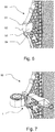
- Fig. 6 shows a vehicle cooling module 50 portion after removal of broken mounting assembly.
- Fig. 7 shows the vehicle cooling module portion with the service member.
- the vehicle cooling module 50 in this case part of a radiator, has a slot 51 and at least one contact side wall 53.
- the vehicle cooling module 50 comprises also a front contact wall 52 which after assembly is facing, and preferably is in contact, with the face wall 19 of the service member 1. If there is a plurality of face walls on the vehicle cooling module 50 as shown in Fig.
- the service member 1 can in fact encapsulate them and a correct positioning of the service member may be ensured after inserting the tongue portion 13 into the slot 51 of the vehicle cooling module 50.
- the inclined top wall 17 and bottom wall 18 can follow the shape of the vehicle cooling module 50 for better alignment and protection of the connection. In Fig. 7 , the top wall 17 is not inclined.
- the contact side wall 53 may comprise a hole or a through-hole 54 for a screw coaxial with the through hole 19 of the service member for fixing together the vehicle cooling module 50 and the service member 1 in a secured manner. In such case, a screw is inserted into both of the openings after assembly, and removed if needed for another replacement of the servicing member if another crash occurs.
- the service member may after assembly and upon crash will break within the connection area 30. The components thereof may then be removed and another servicing member may be mounted.
Landscapes
- Engineering & Computer Science (AREA)
- Chemical & Material Sciences (AREA)
- Combustion & Propulsion (AREA)
- Transportation (AREA)
- Mechanical Engineering (AREA)
- Cooling, Air Intake And Gas Exhaust, And Fuel Tank Arrangements In Propulsion Units (AREA)
Priority Applications (4)
| Application Number | Priority Date | Filing Date | Title |
|---|---|---|---|
| EP20461530.6A EP3900969A1 (fr) | 2020-04-20 | 2020-04-20 | Élément de service pour un module de refroidissement de véhicule et un module de refroidissement de véhicule comportant l'élément de service |
| CN202180027241.3A CN115443226B (zh) | 2020-04-20 | 2021-04-09 | 用于车辆冷却模块的维修构件和具有该维修构件的车辆冷却模块 |
| PCT/EP2021/059295 WO2021213816A1 (fr) | 2020-04-20 | 2021-04-09 | Organe de réparation pour un module de refroidissement de véhicule et module de refroidissement de véhicule doté de l'organe de réparation |
| US17/918,342 US12409722B2 (en) | 2020-04-20 | 2021-04-09 | Service member for a vehicle cooling module and a vehicle cooling module with the service member |
Applications Claiming Priority (1)
| Application Number | Priority Date | Filing Date | Title |
|---|---|---|---|
| EP20461530.6A EP3900969A1 (fr) | 2020-04-20 | 2020-04-20 | Élément de service pour un module de refroidissement de véhicule et un module de refroidissement de véhicule comportant l'élément de service |
Publications (1)
| Publication Number | Publication Date |
|---|---|
| EP3900969A1 true EP3900969A1 (fr) | 2021-10-27 |
Family
ID=70391060
Family Applications (1)
| Application Number | Title | Priority Date | Filing Date |
|---|---|---|---|
| EP20461530.6A Pending EP3900969A1 (fr) | 2020-04-20 | 2020-04-20 | Élément de service pour un module de refroidissement de véhicule et un module de refroidissement de véhicule comportant l'élément de service |
Country Status (4)
| Country | Link |
|---|---|
| US (1) | US12409722B2 (fr) |
| EP (1) | EP3900969A1 (fr) |
| CN (1) | CN115443226B (fr) |
| WO (1) | WO2021213816A1 (fr) |
Citations (3)
| Publication number | Priority date | Publication date | Assignee | Title |
|---|---|---|---|---|
| EP1957346A1 (fr) * | 2005-12-05 | 2008-08-20 | Peguform Gmbh | Module d'extremite avant d'un vehicule automobile, dote d'une fonction de protection et d'absorption d'energie pour un module de refroidissement |
| DE102009043794A1 (de) * | 2009-09-30 | 2011-03-31 | Valeo Gmbh | Reparaturelement zum Ersetzen eines gebrochenen Montagestifts eines Fahrzeugkühlmoduls, Fahrzeugkühlmodul und deren Kombination |
| EP2966393A1 (fr) * | 2014-07-07 | 2016-01-13 | Valeo Autosystemy SP. Z.O.O. | Support intégré pour échangeur de chaleur de véhicules automobiles |
Family Cites Families (11)
| Publication number | Priority date | Publication date | Assignee | Title |
|---|---|---|---|---|
| DE2233737C2 (de) * | 1971-07-12 | 1983-02-03 | Société Anonyme Française du Ferodo, 75017 Paris | Wärmetauscher, insbesondere Kühler für ein Kraftfahrzeug |
| GB1599841A (en) * | 1977-01-24 | 1981-10-07 | Beckley A S | Modular impact energy absorbing system for vehicles |
| JPH0326983Y2 (fr) * | 1985-03-20 | 1991-06-11 | ||
| US6223811B1 (en) * | 1998-10-05 | 2001-05-01 | Valeo Inc. | Support for a cooling device |
| US7117927B2 (en) * | 2004-09-14 | 2006-10-10 | Delphi Technologies, Inc. | Snap-on mounting bracket for heat exchangers |
| JP4479740B2 (ja) * | 2007-03-23 | 2010-06-09 | 日産自動車株式会社 | 車体前部構造及び車体前部配管固定用ブラケット |
| JP4658157B2 (ja) * | 2008-04-28 | 2011-03-23 | 豊田鉄工株式会社 | 車両用冷却部品支持装置 |
| JP5467525B2 (ja) * | 2010-07-28 | 2014-04-09 | スズキ株式会社 | 車両用冷却水リザーブタンクの支持構造 |
| WO2012135956A1 (fr) * | 2011-04-07 | 2012-10-11 | Dana Canada Corporation | Echangeur de chaleur avec support monté de façon robuste |
| US9146061B2 (en) * | 2013-05-06 | 2015-09-29 | Denso International America, Inc. | Fastener-less retained heat exchanger mounting bracket for low installation force |
| CN206510749U (zh) | 2017-01-10 | 2017-09-22 | 宁波吉利汽车研究开发有限公司 | 一种用于车辆冷却装置的保护装置 |
-
2020
- 2020-04-20 EP EP20461530.6A patent/EP3900969A1/fr active Pending
-
2021
- 2021-04-09 CN CN202180027241.3A patent/CN115443226B/zh active Active
- 2021-04-09 US US17/918,342 patent/US12409722B2/en active Active
- 2021-04-09 WO PCT/EP2021/059295 patent/WO2021213816A1/fr not_active Ceased
Patent Citations (3)
| Publication number | Priority date | Publication date | Assignee | Title |
|---|---|---|---|---|
| EP1957346A1 (fr) * | 2005-12-05 | 2008-08-20 | Peguform Gmbh | Module d'extremite avant d'un vehicule automobile, dote d'une fonction de protection et d'absorption d'energie pour un module de refroidissement |
| DE102009043794A1 (de) * | 2009-09-30 | 2011-03-31 | Valeo Gmbh | Reparaturelement zum Ersetzen eines gebrochenen Montagestifts eines Fahrzeugkühlmoduls, Fahrzeugkühlmodul und deren Kombination |
| EP2966393A1 (fr) * | 2014-07-07 | 2016-01-13 | Valeo Autosystemy SP. Z.O.O. | Support intégré pour échangeur de chaleur de véhicules automobiles |
Also Published As
| Publication number | Publication date |
|---|---|
| US12409722B2 (en) | 2025-09-09 |
| WO2021213816A1 (fr) | 2021-10-28 |
| CN115443226A (zh) | 2022-12-06 |
| CN115443226B (zh) | 2025-09-23 |
| US20230147303A1 (en) | 2023-05-11 |
Similar Documents
| Publication | Publication Date | Title |
|---|---|---|
| CN103402802B (zh) | 用于车载电气设备的保护装置 | |
| CN102548788B (zh) | 车辆充电口结构 | |
| CN102905957B (zh) | 车辆碰撞保护装置 | |
| EP3461692B1 (fr) | Protecteur de capteur et véhicule en étant équipé | |
| JP4943494B2 (ja) | 車両衝突時の補機ガイド構造 | |
| EP4026758B1 (fr) | Ensemble de montage de phare de véhicule et véhicule | |
| US9358864B2 (en) | Device for fastening a battery module to a bodyshell of a motor vehicle | |
| JP2026509629A (ja) | 取付ブラケットアセンブリ、傾斜型冷却モジュールアセンブリ及び車両 | |
| JP7141998B2 (ja) | 保護部材及び保護構造 | |
| US6758515B2 (en) | Front end structure of vehicle with crushable zones for collision damage | |
| US12409722B2 (en) | Service member for a vehicle cooling module and a vehicle cooling module with the service member | |
| JP2011121399A (ja) | ヘッドランプの取付構造 | |
| CN117337256A (zh) | 具有经计划断裂的用于固定传感器的固定装置 | |
| WO2015161182A1 (fr) | Adaptateur pour rail d'écrasement et poutre-caisson | |
| US7331414B2 (en) | Protective structure for an electrical circuit device | |
| CN220374282U (zh) | 一种汽车水箱防冲击保护结构 | |
| JPH04243628A (ja) | 自動車のラジエータ支持構造 | |
| CN220298283U (zh) | 车辆 | |
| CN114274903A (zh) | 汽车的外装结构及汽车 | |
| CN220764514U (zh) | A柱前端的防撞结构及车辆 | |
| CN208069398U (zh) | 冷却模组及汽车 | |
| CN217730203U (zh) | 一种散热器安装结构及汽车 | |
| EP4458618A1 (fr) | Unité de fixation de dispositif de détection pour un véhicule industriel | |
| JP5609227B2 (ja) | 車両用電気接続箱及び車両用電気接続箱固定構造 | |
| US20260054539A1 (en) | Vehicle having electric air conditioning compressor protection assembly |
Legal Events
| Date | Code | Title | Description |
|---|---|---|---|
| PUAI | Public reference made under article 153(3) epc to a published international application that has entered the european phase |
Free format text: ORIGINAL CODE: 0009012 |
|
| STAA | Information on the status of an ep patent application or granted ep patent |
Free format text: STATUS: THE APPLICATION HAS BEEN PUBLISHED |
|
| AK | Designated contracting states |
Kind code of ref document: A1 Designated state(s): AL AT BE BG CH CY CZ DE DK EE ES FI FR GB GR HR HU IE IS IT LI LT LU LV MC MK MT NL NO PL PT RO RS SE SI SK SM TR |
|
| B565 | Issuance of search results under rule 164(2) epc |
Effective date: 20200925 |
|
| STAA | Information on the status of an ep patent application or granted ep patent |
Free format text: STATUS: REQUEST FOR EXAMINATION WAS MADE |
|
| 17P | Request for examination filed |
Effective date: 20220427 |
|
| RBV | Designated contracting states (corrected) |
Designated state(s): AL AT BE BG CH CY CZ DE DK EE ES FI FR GB GR HR HU IE IS IT LI LT LU LV MC MK MT NL NO PL PT RO RS SE SI SK SM TR |
|
| P01 | Opt-out of the competence of the unified patent court (upc) registered |
Effective date: 20230528 |
|
| STAA | Information on the status of an ep patent application or granted ep patent |
Free format text: STATUS: EXAMINATION IS IN PROGRESS |
|
| 17Q | First examination report despatched |
Effective date: 20230816 |