EP3900976B1 - Batterie mit doppelkennung, station, system und verfahren zum austausch von batterien - Google Patents
Batterie mit doppelkennung, station, system und verfahren zum austausch von batterien Download PDFInfo
- Publication number
- EP3900976B1 EP3900976B1 EP21168749.6A EP21168749A EP3900976B1 EP 3900976 B1 EP3900976 B1 EP 3900976B1 EP 21168749 A EP21168749 A EP 21168749A EP 3900976 B1 EP3900976 B1 EP 3900976B1
- Authority
- EP
- European Patent Office
- Prior art keywords
- battery
- radio
- exchange
- identifier
- station
- Prior art date
- Legal status (The legal status is an assumption and is not a legal conclusion. Google has not performed a legal analysis and makes no representation as to the accuracy of the status listed.)
- Active
Links
Images


Classifications
-
- B—PERFORMING OPERATIONS; TRANSPORTING
- B60—VEHICLES IN GENERAL
- B60L—PROPULSION OF ELECTRICALLY-PROPELLED VEHICLES; SUPPLYING ELECTRIC POWER FOR AUXILIARY EQUIPMENT OF ELECTRICALLY-PROPELLED VEHICLES; ELECTRODYNAMIC BRAKE SYSTEMS FOR VEHICLES IN GENERAL; MAGNETIC SUSPENSION OR LEVITATION FOR VEHICLES; MONITORING OPERATING VARIABLES OF ELECTRICALLY-PROPELLED VEHICLES; ELECTRIC SAFETY DEVICES FOR ELECTRICALLY-PROPELLED VEHICLES
- B60L53/00—Methods of charging batteries, specially adapted for electric vehicles; Charging stations or on-board charging equipment therefor; Exchange of energy storage elements in electric vehicles
- B60L53/80—Exchanging energy storage elements, e.g. removable batteries
-
- B—PERFORMING OPERATIONS; TRANSPORTING
- B60—VEHICLES IN GENERAL
- B60K—ARRANGEMENT OR MOUNTING OF PROPULSION UNITS OR OF TRANSMISSIONS IN VEHICLES; ARRANGEMENT OR MOUNTING OF PLURAL DIVERSE PRIME-MOVERS IN VEHICLES; AUXILIARY DRIVES FOR VEHICLES; INSTRUMENTATION OR DASHBOARDS FOR VEHICLES; ARRANGEMENTS IN CONNECTION WITH COOLING, AIR INTAKE, GAS EXHAUST OR FUEL SUPPLY OF PROPULSION UNITS IN VEHICLES
- B60K1/00—Arrangement or mounting of electrical propulsion units
- B60K1/04—Arrangement or mounting of electrical propulsion units of the electric storage means for propulsion
-
- B—PERFORMING OPERATIONS; TRANSPORTING
- B60—VEHICLES IN GENERAL
- B60S—SERVICING, CLEANING, REPAIRING, SUPPORTING, LIFTING, OR MANOEUVRING OF VEHICLES, NOT OTHERWISE PROVIDED FOR
- B60S5/00—Servicing, maintaining, repairing, or refitting of vehicles
- B60S5/06—Supplying batteries to, or removing batteries from, vehicles
-
- H—ELECTRICITY
- H02—GENERATION; CONVERSION OR DISTRIBUTION OF ELECTRIC POWER
- H02J—ELECTRIC POWER NETWORKS; CIRCUIT ARRANGEMENTS OR SYSTEMS FOR SUPPLYING OR DISTRIBUTING ELECTRIC POWER; SYSTEMS FOR STORING ELECTRIC ENERGY
- H02J7/00—Circuit arrangements for charging or discharging batteries or for supplying loads from batteries
- H02J7/40—Circuit arrangements for charging or discharging batteries or for supplying loads from batteries characterised by the exchange of charge or discharge related data
- H02J7/44—Circuit arrangements for charging or discharging batteries or for supplying loads from batteries characterised by the exchange of charge or discharge related data between battery management systems and power sources
-
- B—PERFORMING OPERATIONS; TRANSPORTING
- B60—VEHICLES IN GENERAL
- B60K—ARRANGEMENT OR MOUNTING OF PROPULSION UNITS OR OF TRANSMISSIONS IN VEHICLES; ARRANGEMENT OR MOUNTING OF PLURAL DIVERSE PRIME-MOVERS IN VEHICLES; AUXILIARY DRIVES FOR VEHICLES; INSTRUMENTATION OR DASHBOARDS FOR VEHICLES; ARRANGEMENTS IN CONNECTION WITH COOLING, AIR INTAKE, GAS EXHAUST OR FUEL SUPPLY OF PROPULSION UNITS IN VEHICLES
- B60K1/00—Arrangement or mounting of electrical propulsion units
- B60K1/04—Arrangement or mounting of electrical propulsion units of the electric storage means for propulsion
- B60K2001/0405—Arrangement or mounting of electrical propulsion units of the electric storage means for propulsion characterised by their position
- B60K2001/0422—Arrangement under the front seats
-
- B—PERFORMING OPERATIONS; TRANSPORTING
- B60—VEHICLES IN GENERAL
- B60K—ARRANGEMENT OR MOUNTING OF PROPULSION UNITS OR OF TRANSMISSIONS IN VEHICLES; ARRANGEMENT OR MOUNTING OF PLURAL DIVERSE PRIME-MOVERS IN VEHICLES; AUXILIARY DRIVES FOR VEHICLES; INSTRUMENTATION OR DASHBOARDS FOR VEHICLES; ARRANGEMENTS IN CONNECTION WITH COOLING, AIR INTAKE, GAS EXHAUST OR FUEL SUPPLY OF PROPULSION UNITS IN VEHICLES
- B60K1/00—Arrangement or mounting of electrical propulsion units
- B60K1/04—Arrangement or mounting of electrical propulsion units of the electric storage means for propulsion
- B60K2001/0455—Removal or replacement of the energy storages
- B60K2001/0466—Removal or replacement of the energy storages from above
-
- B—PERFORMING OPERATIONS; TRANSPORTING
- B60—VEHICLES IN GENERAL
- B60Y—INDEXING SCHEME RELATING TO ASPECTS CROSS-CUTTING VEHICLE TECHNOLOGY
- B60Y2200/00—Type of vehicle
- B60Y2200/10—Road Vehicles
- B60Y2200/12—Motorcycles, Trikes; Quads; Scooters
- B60Y2200/126—Scooters
-
- B—PERFORMING OPERATIONS; TRANSPORTING
- B60—VEHICLES IN GENERAL
- B60Y—INDEXING SCHEME RELATING TO ASPECTS CROSS-CUTTING VEHICLE TECHNOLOGY
- B60Y2410/00—Constructional features of vehicle sub-units
- B60Y2410/111—Aggregate identification or specification, e.g. using RFID
-
- B—PERFORMING OPERATIONS; TRANSPORTING
- B60—VEHICLES IN GENERAL
- B60Y—INDEXING SCHEME RELATING TO ASPECTS CROSS-CUTTING VEHICLE TECHNOLOGY
- B60Y2410/00—Constructional features of vehicle sub-units
- B60Y2410/115—Electric wiring; Electric connectors
-
- Y—GENERAL TAGGING OF NEW TECHNOLOGICAL DEVELOPMENTS; GENERAL TAGGING OF CROSS-SECTIONAL TECHNOLOGIES SPANNING OVER SEVERAL SECTIONS OF THE IPC; TECHNICAL SUBJECTS COVERED BY FORMER USPC CROSS-REFERENCE ART COLLECTIONS [XRACs] AND DIGESTS
- Y02—TECHNOLOGIES OR APPLICATIONS FOR MITIGATION OR ADAPTATION AGAINST CLIMATE CHANGE
- Y02T—CLIMATE CHANGE MITIGATION TECHNOLOGIES RELATED TO TRANSPORTATION
- Y02T10/00—Road transport of goods or passengers
- Y02T10/60—Other road transportation technologies with climate change mitigation effect
- Y02T10/70—Energy storage systems for electromobility, e.g. batteries
-
- Y—GENERAL TAGGING OF NEW TECHNOLOGICAL DEVELOPMENTS; GENERAL TAGGING OF CROSS-SECTIONAL TECHNOLOGIES SPANNING OVER SEVERAL SECTIONS OF THE IPC; TECHNICAL SUBJECTS COVERED BY FORMER USPC CROSS-REFERENCE ART COLLECTIONS [XRACs] AND DIGESTS
- Y02—TECHNOLOGIES OR APPLICATIONS FOR MITIGATION OR ADAPTATION AGAINST CLIMATE CHANGE
- Y02T—CLIMATE CHANGE MITIGATION TECHNOLOGIES RELATED TO TRANSPORTATION
- Y02T10/00—Road transport of goods or passengers
- Y02T10/60—Other road transportation technologies with climate change mitigation effect
- Y02T10/7072—Electromobility specific charging systems or methods for batteries, ultracapacitors, supercapacitors or double-layer capacitors
Definitions
- the present invention relates to the field of electric vehicles, and in particular electric bicycles, tricycles or quadricycles, and similar mobility solutions.
- a preferred application of the present invention relates to electric scooters.
- the invention relates more particularly to electric vehicles which carry at least one battery to provide electricity for powering one or more electric propulsion motors, and which are configured so that the user can exchange the battery(ies) themselves when the latter is discharged.
- exchanging a battery may consist, for a user, of going near an exchange and recharging point of a network of battery exchange stations, removing the discharged battery from their vehicle, exchanging, in a suitable device which may be called for example a "station” or "exchange station", the discharged battery for a charged battery, and placing the charged battery thus recovered in their vehicle.
- This type of network of battery exchange stations is currently developing and is proving particularly useful in urban areas. Indeed, the vehicles targeted, particularly scooters, are particularly well-suited to travel there, the distances to be covered are relatively short, and it is easy to establish a network of battery exchange stations with a coherent geographical layout that can be used by many users.
- a battery of generally right prismatic shape in this case parallelepiped, comprising on one face a carrying and handling handle, and on an opposite face an electrical connector.
- the battery is thus adapted to be inserted into a correspondingly shaped receiving housing provided in the vehicle receiving the battery.
- the housing has on its bottom a connector adapted to cooperate by plugging with that of the battery, so as to ensure an electrical connection between the battery and the electrical system of the vehicle.
- the battery is also adapted to be inserted into a housing of an exchange and charging station or terminal, in a similar manner to its insertion into the housing of the vehicle.
- the housing has on its bottom an electrical connector adapted for recharging the battery.
- the stations are located in public spaces, or at least open to the public, the reception areas and their connectors are likely to be damaged, for example blocked, by malicious people.
- the document US2016267579A1 proposes, in the context of battery rental, to identify on the one hand the battery and on the other hand a user, in order to associate them. In particular, this involves knowing which user has which battery at any time. While this solution allows for user identification, it does not allow for reliable identification of the battery.
- the document TW201201106 describes that one solution for reliably identifying a battery is to combine two means of identification, namely identification by an RFID chip or smart card, and identification using a pattern that can be read by an optical sensor (barcode or other pattern). This helps combat counterfeiting or theft of batteries.
- the invention thus aims to propose a device making it possible to respond to the aforementioned problems.
- the invention relates to an electric vehicle battery comprising a housing containing at least one battery cell suitable for storing electrical energy and an electronic battery management card, the battery further comprising a electrical connector of the battery.
- the battery comprises a radio-identification chip separate from the electronic card and the electronic card comprises a unique identifier of the battery, the unique identifier being able to be read by a suitable electronic device when the electrical connector of the battery is connected to said electronic device.
- this helps to ensure the integrity of the batteries to some extent, by verifying that the correlation between the RFID chip ID and the unique battery ID is correct, and in particular remains unchanged throughout the life of the battery and its multiple exchanges.
- radio-ID chip identification allows for initial remote identification of the battery. This initial wireless identification is particularly advantageous in the context of a self-service battery exchange network. Indeed, an electric vehicle battery, particularly a scooter battery, is relatively heavy to ensure satisfactory autonomy. A battery can typically weigh around ten kilograms. Radio-ID chip identification allows an exchange station equipped with a radio-ID chip reader to detect that a battery is nearby, without the user having to take any action. Thus, the user can use both hands to carry the battery until it is deposited in the battery exchange station.
- the identification of the radio-identification chip may have the objective of precisely identifying a battery among all the batteries that can be exchanged in the network of battery exchange stations, or of simply ensuring that the battery belongs to the exchange network, without the exact identity of the battery being determined or used.
- the unique battery identifier read when the battery is connected for charging at a battery exchange station, allows for strong and certain identification of a particular battery.
- the degree of reliability of the battery identification, individually, can be higher than that of identification by wireless means.
- the electronic card containing the unique battery identifier can typically be a battery management system, commonly referred to by the English acronym BMS for "Battery Management System".
- the radio-identification chip can advantageously be housed inside the housing.
- a radio-identification chip integrated into the battery housing greatly limits the risks of damage to the chip, disassembly or exchange thereof.
- two radio-identification chips are located in two locations distant from the battery.
- the presence of two chips makes detection more reliable.
- radio-identification makes it possible to detect the presence of a battery authorized to be exchanged near an exchange station, this detection is carried out very reliably, regardless of the orientation of the battery when it approaches the exchange station.
- the invention also relates to a battery exchange station for an electric vehicle, comprising a radio-identification reader adapted to communicate with a radio-identification chip of a battery and further comprising at least one station connector adapted to be connected to the electrical connector of the battery for reading a unique identifier of the battery.
- the invention thus also relates to an exchange station, complementary to the battery which is the subject of the present invention.
- the station allows the reading and use of the two identification information carried by the battery.
- the station may comprise a set of station housings each adapted to receive a battery, each station housing comprising a device for closing said station housing controlled by an automated opening and closing system, said automated system being configured to control the opening of a station housing in response to the detection by the radio-identification reader of a proximity of a radio-identification chip to a battery and to a confirmation, on the basis of an identification of the detected radio-identification chip, that the battery is authorized to be exchanged.
- the double identification of the battery is of particular interest with this type of exchange station which secures access to the station's housings and to the batteries they contain by a physical means such as a door, a shutter, etc.
- the first identification carried out using the radio-identification chip allows the opening of a sealing means, for example a shutter, which has the dual effect of indicating to the user in which housing to place the discharged battery and of giving access to this housing to place the discharged battery there.
- the battery exchange station may include a communication system, wired or wireless, allowing data exchange with a remote computer system.
- the remote computer system comprising for example one or more servers, whether it is a computer system with centralized or distributed architecture, allows access to data relating to the batteries and their identification. In particular, it allows the consistency of the two battery identification information to be validated, which secures the system.
- the data contained by the remote computer system may further include, for each battery, an identifier of a user associated with the battery.
- the data contained by the remote computer system may include, in association with a user's identifier, data relating to a user's subscription to the battery exchange system.
- the opening of a station housing containing a charged battery can be ordered after verification, by communication with the remote computer system, of the data relating to the user's subscription.
- the delivery of a new battery may thus be conditional on the authorization of such delivery, after having for example verified the validity of the user's subscription, that the user does not misuse the system (excessive number of exchanges over a given period, etc.).
- the battery exchange system may further comprise an electric vehicle adapted to receive a battery from a battery exchange station of said system, the vehicle comprising means adapted to read the unique identifier of the battery, the vehicle further comprising communication means adapted to communicate to the remote computer system said unique identifier of the battery and an identifier of the vehicle.
- connection between the remote computer system and devices other than the exchange stations makes it possible to further secure the system by ensuring, for example, that the vehicle using a battery is indeed that of the user who borrowed the battery. This also makes it possible, for example, to develop vehicle fleet logic, by identifying groups of vehicles associated with groups of users.
- the method may further comprise a step of verifying, in the remote computer system, the correspondence between the radio identification chip identifier, the unique identifier of the battery, and the identifier of the user associated with the battery.
- FIG. 1 represents, in a three-dimensional view, an electric scooter comprising a device for receiving a battery according to one embodiment of the invention.
- the scooter 1 is an electrically powered scooter.
- a battery 2 is intended to provide the energy necessary for the propulsion of the scooter 1.
- the battery powers an electronic power system which provides power An electric motor, which propels the scooter.
- the vehicle can be configured to accommodate more than one battery, for example two batteries. This increases the vehicle's range, or ensures sufficient range for a vehicle requiring significant power to move. This may concern a heavier vehicle, and/or one with a significant expected load, for example a vehicle intended for deliveries.
- the vehicle can have more than two batteries, for example three batteries.
- the scooter 1 has a housing 3 for receiving and connecting the battery 2.
- the housing 3 is very easy to access, being located, in the example shown here, under the saddle 4 of the scooter.
- the area under the saddle 4 is, in a known manner, accessible by tilting the saddle 4.
- the housing 3 may essentially be in the form of a well allowing substantially vertical insertion of the battery into the housing.
- the scooter of the Figure 1 is particularly well suited for quick battery exchange, for example to replace a discharged battery with a charged one.
- Replacing battery 2 on scooter 1 thus simply involves opening seat 4, pulling battery 2 out of housing 3, inserting a new battery into housing 3, and closing seat 4.
- the battery 2 comprises in a housing a set of electric cells, for example lithium-ion technologies, although any other battery technology is conceivable within the framework of the present invention (in particular lead, nickel-cadmium, nickel-metal-hydride, lithium-polymer, lithium-iron-phosphate, aluminum, etc.).
- the nominal voltage of the battery is adapted to the intended application, and may be, for example, 36V, 48V, 60V, 72V, or any other appropriate voltage.
- the battery 2 has a general shape adapted to the housing 3, and comprises a handle 5 located in the preferred area for gripping the battery, according to the direction of insertion of the battery 2 into the housing 3.
- the housing 3 of the scooter 1 allowing a substantially vertical introduction, the handle 5 is provided on a so-called upper face 6 of the battery.
- the battery 2 has a substantially parallelepiped shape, extending in its direction of insertion into the housing 3 of the scooter 1, and comprising rounded edges.
- the rounded edges of the battery facilitate its insertion into the housing 3 and also make its handling more pleasant and less blunt for the user.
- the battery 2 may comprise, in addition to the battery cells, one or more electronic cards, which may include in particular a microprocessor and, where appropriate, a memory. These electronic means may be intended to carry out various functions linked to the management of the battery, in particular its charging, to the recording of data relating to its use (voltage, charge/discharge currents, time information, etc.).
- This (or these) electronic card forms a battery management system, commonly referred to by the English acronym BMS for "Battery Management System".
- the battery management system includes a unique identifier, which in fact forms a unique identifier for the battery. This unique identifier cannot be modified, or, if necessary, only with appropriate means and certain authentication. In practice, the unique identifier is assigned at the factory during the manufacture of the battery and can only be modified as part of exceptional maintenance operations.
- the face of the battery opposite the face on which the handle 5 is arranged which can be called the base 7 of the battery, comprises an electrical connector for the battery 8.
- the base 7 also constitutes a face on which the battery can be placed on the ground, and can thus comprise support pads 9.
- electrical connector is used in the singular, it is a set of several electrical contacts grouped and organized in the form of a socket, suitable for connecting a corresponding socket.
- the electrical connector of the battery 8 is called “female”, in that it is formed in the battery 2 and is adapted to receive a “male” electrical connector inserted therein.
- the electrical connector of the battery 8 is thus provided with a set of contacts females adapted to receive corresponding male contacts.
- the contacts can be arranged so as to allow a connection of the battery in several orientations.
- the contacts can be symmetrical, namely a central contact and two contacts distributed on either side, allowing a connection in two orientations.
- the polarity can be reversed in the connectors (positive pole in the center, negative poles on either side).
- the male or female character of the connectors can be reversed, the battery then having a male battery electrical connector 8.
- the battery also includes centering holes 10, allowing the battery to be centered in its receiving housing 3, and guided when connecting the battery's electrical connector 8.
- the vehicle's electrical connector can in fact be mounted floating so that it can move in the plane formed by its support.
- this alignment function can be provided, as an alternative or in addition, by elastic means provided between a fixed structure of the vehicle and a support for the vehicle's electrical connector.
- the battery connector 8 also has additional electrical contacts, in addition to the poles allowing the battery to be charged and discharged.
- communication between the battery and the vehicle, and vice versa can be achieved by contactless communication means.
- one of the additional electrical contacts may be shorter than the others, so detecting its connection can be used to ensure that the battery is correctly seated, with its connector properly connected.
- the battery 2 is provided with at least one radio-identification chip.
- a radio frequency identification chip commonly called an RFID chip (from the English radio frequency identification), is a device that allows data to be stored and retrieved remotely.
- a radio-identification chip can also be referred to as “radio-label”, “RFID tag”, “RFID transponder” according to the contraction of the English terms “transmitter” and “responder”, sometimes Frenchified by the term “transponder”.
- Radio frequency identification chips usually come in the form of a label, which can be stuck on or embedded in an object.
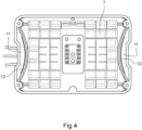
- FIG. 4 represents an advantageous example of the implantation of radio-identification chips in the battery 2.
- the Figure 4 represents in particular, the base 7 of the battery, seen from inside the battery in a sectional view.
- two lateral housings 11 are formed on either side of the battery.
- a radio-identification chip 12 is housed in each of the lateral housings 11.
- the radio-identification chip 11 can be simply enclosed there, or it can be glued there for better support.
- the radio identification chip 11 (or in this case, the two radio identification chips 11) is encapsulated in a non-removable manner in the battery, at least for the user of the battery.
- the positioning of the radio identification chips allows at least one radio identification chip to be correctly oriented with respect to a charging station equipped with a suitable reader on the front, when the battery 2 is brought close to the station.
- the radio-identification chip(s) may, for example, simply be glued to the battery, for example on its outer wall or in a cavity accessible from the outside of the battery. An attempt to remove the radio-identification chip 12 would result in destroying the radio-identification chip and rendering it unusable.
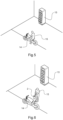
- THE figures 5 to 13 show the different steps of a sequence for exchanging batteries of an electric vehicle in an exchange and charging station 13 of a network of battery exchange stations 13.
- the vehicle shown as an example is an electric two-wheeled vehicle of the motorcycle type.
- the exchange sequence is identical for exchanging a battery of the scooter 1.
- FIG. 5 represents the arrival of an electric vehicle, for example a motorcycle 14, near a battery exchange and recharging station 13.
- the user 15 of the motorcycle 14 parks it near the station 13.
- the user 15 got off the motorcycle 14. He removed the battery 2 (or where applicable the batteries), which is discharged, or insufficiently charged, from the vehicle. To do this, the means for holding the battery 2 in or on the vehicle 2 were released (for example, the saddle was lifted or tilted), and the battery was detached from the vehicle.
- the station 13 comprises a radio-identification reader 16, making it possible to remotely detect and read the radio-identification chip(s) 12 of the battery 2.
- Reading the radio-identification chip 12 makes it possible to determine whether the battery is authorized to be exchanged via the station 13. This may involve ensuring that the battery is one of the batteries in the exchange network. This may involve precisely identifying a battery among the batteries in the exchange network. This may involve verifying the origin of the battery, i.e. from which station it was delivered, and when.
- This authorization may, in certain cases, be verified at the station 13 itself but is more commonly verified by interrogating a remote computer system 20.
- the remote computer system 20 contains the information necessary to authorize or not the exchange of the battery 2 on the basis of its identification permitted by the radio-identification chip.
- the remote computer system 20 transmits a response to the station 13, as to the authorization (or not) of the exchange of the battery 2.
- Communication between the station 13 and the remote computer system 20 may be achieved using various communication networks, wired, fiber, and/or wireless communication networks.
- Medium or long-range communication protocols can be used, including 5G, LoRa, Sigfox, NB-loT, LTE, GPRS, UMTS, GSM (registered trademarks).
- the use of alternative protocols of this type, known or future, is possible.
- the protocols Short-range wireless communication protocols can be used among: NFC, RFID, Bluetooth, including Bluetooth Low Energy, Lifi, and Zigbee (registered trademarks).
- the use of alternative protocols of this type, known or future, is conceivable.
- the station 13 will indicate to the user 15 where to deposit the battery 2.
- the first remote identification carried out using the radio identification chip is particularly advantageous in the context of a self-service battery exchange network. It allows an exchange station equipped with a radio identification chip reader to detect that a battery is nearby, without the user having to take any action. Thus, the user can use both hands to carry the battery until it is deposited in the battery exchange station.
- This first identification makes it possible, for example, to validate that the battery can be exchanged in the exchange station, in particular because according to this first identification the battery is recognized as being a battery belonging to the set of batteries in the battery exchange system.
- the unique identifier of the battery read when the battery is connected for charging in the battery exchange station will then allow a strong and certain identification of the particular battery, and will validate that a charged battery can be provided to the user in exchange, as explained below.
- the station housing 18 in which the battery 2 must be deposited is thus clearly indicated to the user, while physical access to this station housing 18 is permitted.
- the user 15 then places the battery 2 in the station housing 18 which is open.
- the battery 2 then connects, for example under the effect of its own weight, to a connector of the station corresponding to the connector of the battery 8.
- the flap 17 of the station housing 18 in which the battery 2 has been placed then closes, as illustrated in Figure 10 .
- Connecting battery 2 to station 13 will allow it to be recharged. Initially, it allows information stored in the system to be read.
- battery management that is, in the electronic card it contains. In particular, the unique identifier of the battery is read.
- the unique identifier of the battery allows a strong and certain identification of a particular battery.
- the unique identifier in the example shown here, is transmitted to the remote computer system 20. This makes it possible, if necessary, to verify that the correspondence between the unique identifier of the battery and the identity of the battery determined on the basis of the radio-identification chip that it carries.
- the station is authorized to deliver a recharged battery to the user 15.
- the user identifier is then associated with a charged battery that is present in the station 13.
- the user identifier is associated with the unique identifier of the battery.
- a flap 17 of the station 13 which closed the station housing 18 which contains the charged battery 2 which has been associated with the user is open.
- the user 15 grasps the battery 2 which is accessible by the handle 5 of the battery 2.
- the user removes the battery 2 from the station 13.
- the flap of the station housing which contained this battery closes, in order to secure the station housing.
- the user 15 approaches his vehicle, namely the motorcycle 14, in order to install the charged battery 2 that he has recovered.
- Dual battery identification thus enables a reliable and safe battery exchange service for the user.
- the first detection of the battery using a radio-identification chip allows a battery exchange and charging station to detect the battery remotely from the station, without any action being required from the user.
- the user can hold and place the discharged battery using both hands, which is advantageous due to the weight of the battery.
- the identification of a second identifier namely a unique battery identifier, is tamper-proof.
Landscapes
- Engineering & Computer Science (AREA)
- Mechanical Engineering (AREA)
- Power Engineering (AREA)
- Transportation (AREA)
- Chemical & Material Sciences (AREA)
- Combustion & Propulsion (AREA)
- Charge And Discharge Circuits For Batteries Or The Like (AREA)
- Electric Propulsion And Braking For Vehicles (AREA)
Claims (13)
- Batterie (2) für ein Elektrofahrzeug, die ein Gehäuse umfasst, das mindestens eine Batteriezelle enthält, die zur Speicherung elektrischer Energie geeignet ist, wobei die Batterie (2) einen elektrischen Anschluss der Batterie (8) und einen Funk-Identifikationschip (12) umfasst, der eine Kennung umfasst;dadurch gekennzeichnet, dass die Batterie eine elektronische Karte zur Verwaltung der Batterie umfasst, die sich von dem Funk-Identifikationschip (12) unterscheidet, und dass die elektronische Karte eine eindeutige Kennung der Batterie umfasst,wobei die eindeutige Kennung von einer geeigneten elektronischen Vorrichtung gelesen werden kann, wenn der elektrische Anschluss der Batterie (8) mit der elektronischen Vorrichtung verbunden ist.
- Batterie nach Anspruch 1, wobei der Funk-Identifikationschip (12) im Inneren des Gehäuses untergebracht ist.
- Batterie nach Anspruch 1 oder Anspruch 2, die zwei Funk-Identifikationschips (12) umfasst, die sich an zwei von der Batterie (2) entfernten Stellen befinden.
- Batterieaustauschsystem, das Folgendes umfasst:- eine Batterieaustauschstation (13) für ein Elektrofahrzeug, die Folgendes umfasst:o ein Funk-Identifikationslesegerät (16), das dazu geeignet ist, mit einem Funk-Identifikationschip (12) einer Batterie, der eine Kennung umfasst, zu kommunizieren,o einen Stationsanschluss, der dazu geeignet ist, mit dem elektrischen Anschluss der Batterie (8) verbunden zu werden, um eine eindeutige Kennung der Batterie, die sich von der Kennung des Funk-Identifikationschips unterscheidet, auszulesen und diese an ein entferntes Computersystem zu übertragen, undo ein drahtgebundenes oder drahtloses Kommunikationssystem, das einen Datenaustausch mit dem entfernten Computersystem (20) ermöglicht,- das entfernte Computersystem, das Daten in Bezug auf mehrere Batterien (2) enthält und das dazu konfiguriert ist, die Übereinstimmung zwischen der eindeutigen Kennung der Batterie und der Kennung des Funk-Identifikationschip, den sie trägt, zu überprüfen.
- Batterieaustauschstation nach Anspruch 4, wobei die Batterieaustauschstation (13) eine Anordnung von Stationsgehäusen (18) umfasst, die dazu geeignet sind, jeweils eine Batterie aufzunehmen, wobei jedes Stationsgehäuse (18) eine Absperrvorrichtung für das Stationsgehäuse (18) umfasst, die durch ein automatisches Öffnungs- und Schließsystem gesteuert wird, wobei das automatisierte System dazu konfiguriert ist, das Öffnen eines Stationsgehäuses (18) als Reaktion auf das Detektieren der Nähe eines Funk-Identifikationschips (12) einer Batterie (2) und das Bestätigen anhand einer Kennung des detektierten Funk-Identifikationschips (12), dass die Batterie (2) autorisiert ist, ausgetauscht zu werden, zu steuern.
- Batterieaustauschstation nach Anspruch 4 oder Anspruch 5, wobei die im entfernten Computersystem (20) enthaltenen Daten für jede Batterie (2) Folgendes umfassen:- eine Kennung jedes Funk-Identifikationschips (12), den die Batterie (2) umfasst; und- die eindeutige Kennung, die die elektronische Karte der Batterie umfasst.
- Batterieaustauschsystem nach Anspruch 6, wobei die im entfernten Computersystem (20) enthaltenen Daten ferner für jede Batterie (2) eine der Batterie zugeordnete Kennung eines Benutzers (15) umfassen.
- Batterieaustauschsystem nach Anspruch 7, wobei die im entfernten Computersystem (20) enthaltenen Daten in Verbindung mit der Kennung eines Benutzers Daten umfassen, die sich auf ein Abonnement des Benutzers (15) für das Batterieaustauschsystem beziehen.
- Batterieaustauschsystem nach Anspruch 8, wobei das Öffnen eines Stationsgehäuses (18), das eine geladene Batterie (2) enthält, nach dem Überprüfen der Daten, die sich auf das Abonnement des Benutzers beziehen, durch Kommunikation mit dem entfernten Computersystem (20) gesteuert wird.
- Batterieaustauschsystem nach einem der Ansprüche 4 bis 9, das mehrere Austauschstationen (13) umfasst, die dazu geeignet sind, mit demselben entfernten Computersystem (20) zu kommunizieren, und so ein Netzwerk von Batterieaustauschstationen bilden.
- Batterieaustauschsystem nach einem der Ansprüche 4 bis 10, das ferner ein Elektrofahrzeug umfasst, das dazu geeignet ist, eine Batterie (2) aufzunehmen, die von einer Batterieaustauschstation (13) des Systems kommt, wobei das Fahrzeug Mittel umfasst, die dazu geeignet sind, die eindeutige Kennung der Batterie zu lesen, wobei das Fahrzeug ferner Kommunikationsmittel umfasst, die dazu geeignet sind, die eindeutige Kennung der Batterie (2) und eine Kennung des Fahrzeugs an das entfernte Computersystem (20) zu kommunizieren.
- Verfahren zum Austauschen einer Batterie eines Elektrofahrzeugs durch einen Benutzer (15), um eine entladene Batterie (2) gegen eine geladene Batterie (2) auszutauschen, das die folgenden Schritte umfasst:- Bereitstellen einer entladenen Batterie (2) in der Nähe einer Batterieaustauschstation (13);- Detektieren der Nähe eines Funk-Identifikationschips (12), den die entladene Batterie (2) umfasst, durch die Austauschstation (13) und Bestimmen einer Kennung des Funk-Identifikationschips (12);- Bestätigen anhand einer Kennung des Chips, dass die Batterie autorisiert ist, ausgetauscht zu werden;- Angeben eines Empfangsorts für die entladene Batterie (2) durch die Station (13);- Anschließen eines elektrischen Anschlusses der Batterie (8) an einen Anschluss der Station am angegebenen Empfangsort;- Lesen einer eindeutigen Kennung der Batterie in einer elektronischen Karte der Batterie, die sich vom Funk-Identifikationschip unterscheidet, über den Anschluss der Batterie;- Übertragen der eindeutigen Kennung der Batterie an ein entferntes Computersystem;- Überprüfen der Übereinstimmung zwischen der eindeutigen Kennung der Batterie und der Kennung des Funk-Identifikationschips, den sie trägt;- Überprüfen in einem entfernten Computersystem (20), dass die Daten, die sich auf den Benutzer beziehen und unter Verwendung einer Kennung eines Benutzers der Batterie zugeordnet sind, das Liefern einer geladenen Batterie (2) autorisieren;- wenn das Liefern einer geladenen Batterie (2) autorisiert ist, Zuordnen der Kennung des Benutzers zu einer geladenen Batterie (2), die die Austauschstation (13) enthält, im entfernten Computersystem (20) und Liefern der aufgeladenen Batterie (2).
- Austauschverfahren nach Anspruch 12, das ferner einen Schritt des Überprüfens der Übereinstimmung zwischen der Kennung des Funk-Identifikationschips, der eindeutigen Kennung der Batterie und der der Batterie zugeordneten Kennung des Benutzers in dem entfernten Computersystem (20) umfasst.
Applications Claiming Priority (1)
| Application Number | Priority Date | Filing Date | Title |
|---|---|---|---|
| FR2003973A FR3109471B1 (fr) | 2020-04-21 | 2020-04-21 | Batterie à double identification, station, système et procédé d’échange de batteries associés |
Publications (2)
| Publication Number | Publication Date |
|---|---|
| EP3900976A1 EP3900976A1 (de) | 2021-10-27 |
| EP3900976B1 true EP3900976B1 (de) | 2025-03-26 |
Family
ID=71575465
Family Applications (1)
| Application Number | Title | Priority Date | Filing Date |
|---|---|---|---|
| EP21168749.6A Active EP3900976B1 (de) | 2020-04-21 | 2021-04-16 | Batterie mit doppelkennung, station, system und verfahren zum austausch von batterien |
Country Status (2)
| Country | Link |
|---|---|
| EP (1) | EP3900976B1 (de) |
| FR (1) | FR3109471B1 (de) |
Families Citing this family (1)
| Publication number | Priority date | Publication date | Assignee | Title |
|---|---|---|---|---|
| FR3145514A1 (fr) * | 2023-02-08 | 2024-08-09 | Psa Automobiles Sa | Vehicule automobile comprenant au moins un module de batterie d’habitacle, et procede sur la base d’un tel vehicule |
Citations (1)
| Publication number | Priority date | Publication date | Assignee | Title |
|---|---|---|---|---|
| TW201201106A (en) * | 2010-06-17 | 2012-01-01 | li-he Yao | Object identification method |
Family Cites Families (3)
| Publication number | Priority date | Publication date | Assignee | Title |
|---|---|---|---|---|
| JP6671016B2 (ja) * | 2015-03-09 | 2020-03-25 | パナソニックIpマネジメント株式会社 | 貸与システムおよび貸与管理方法 |
| JP6363755B1 (ja) * | 2017-03-23 | 2018-07-25 | 本田技研工業株式会社 | 管理装置、管理システム及びプログラム |
| TWI686981B (zh) * | 2018-08-22 | 2020-03-01 | 光陽工業股份有限公司 | 具有燈號顯示功能的抽取電池裝置 |
-
2020
- 2020-04-21 FR FR2003973A patent/FR3109471B1/fr active Active
-
2021
- 2021-04-16 EP EP21168749.6A patent/EP3900976B1/de active Active
Patent Citations (1)
| Publication number | Priority date | Publication date | Assignee | Title |
|---|---|---|---|---|
| TW201201106A (en) * | 2010-06-17 | 2012-01-01 | li-he Yao | Object identification method |
Also Published As
| Publication number | Publication date |
|---|---|
| FR3109471A1 (fr) | 2021-10-22 |
| EP3900976A1 (de) | 2021-10-27 |
| FR3109471B1 (fr) | 2022-08-26 |
Similar Documents
| Publication | Publication Date | Title |
|---|---|---|
| JP7339998B2 (ja) | 電気エネルギー貯蔵装置の販売、充電及び双方向配電のための装置、システム及び方法 | |
| EP2539167B1 (de) | System zum anschliessen von batterien für ein elektrofahrzeug und entsprechender satz von batterien | |
| EP3122960A1 (de) | Unterirdisches parkhaus für elektrofahrzeuge | |
| FR2938818A1 (fr) | Systeme de stockage et de verrouillage de cycles | |
| FR3014825A1 (fr) | Systeme automatique de stockage de cycles et cycle pour un tel systeme. | |
| FR3003534A1 (fr) | Systeme automatique de stockage de cycles et batterie pour un tel systeme. | |
| EP2781440A1 (de) | Automatisches System zur Speicherung von Zyklen, und Batterie für ein solches System | |
| EP3900976B1 (de) | Batterie mit doppelkennung, station, system und verfahren zum austausch von batterien | |
| CA2852527A1 (fr) | Procede de gestion dynamique et previsionnel du rechargement electrique de batteries | |
| FR3054352A1 (fr) | Dispositif de stockage de vehicules electriques legers partages | |
| EP3735373B1 (de) | Zur kompakten lagerung geeigneter roller | |
| FR2656450A1 (fr) | Systeme de transport urbain. | |
| EP2727213B1 (de) | Ladeterminal für ein elektrisches fahrzeug sowie station und system mit einem solchen terminal | |
| EP3257028B1 (de) | Halbautomatische anzeigeeinheit für gaszylinder und zugehöriges verfahren | |
| US20220278377A1 (en) | A portable device and an apparatus for replacing used battery of the portable device | |
| EP2781446A1 (de) | Automatisches System zur Speicherung von Zyklen, und Batterie für ein solches System | |
| EP3752414B1 (de) | Verfahren zum wiederaufladen eines elektrischen energiespeichers zur speicherung elektrischer energie von mehreren fahrzeugen | |
| FR2988068A1 (fr) | Systeme automatique de stockage de cycles, cycle pour un tel systeme et utilisation d'une batterie pour un tel cycle. | |
| WO2013001255A1 (fr) | Procede et systeme de securisation d'un vehicule propose a la location, et vehicule securise | |
| FR2978415A1 (fr) | Systeme automatique de stockage de cycles et ensemble pour un tel systeme. | |
| FR3026213A1 (fr) | Systeme de gestion d'une flotte de kits d'assistance electrique mis a la disposition d'utilisateurs pour la motorisation de vehicules et equipement d'entreposage correspondant | |
| EP3794703B1 (de) | Vorrichtung zur steuerung und unterstützung des ladeausgleichs eines batteriemoduls sowie entsprechendes verfahren und bausatz | |
| FR3076535A1 (fr) | Vehicule a propulsion humaine apte a un stockage compact | |
| FR2937934A1 (fr) | Procede de remplacement d'une batterie | |
| FR2983616A1 (fr) | Dispositif de recharge de batteries electriques |
Legal Events
| Date | Code | Title | Description |
|---|---|---|---|
| PUAI | Public reference made under article 153(3) epc to a published international application that has entered the european phase |
Free format text: ORIGINAL CODE: 0009012 |
|
| STAA | Information on the status of an ep patent application or granted ep patent |
Free format text: STATUS: THE APPLICATION HAS BEEN PUBLISHED |
|
| AK | Designated contracting states |
Kind code of ref document: A1 Designated state(s): AL AT BE BG CH CY CZ DE DK EE ES FI FR GB GR HR HU IE IS IT LI LT LU LV MC MK MT NL NO PL PT RO RS SE SI SK SM TR |
|
| B565 | Issuance of search results under rule 164(2) epc |
Effective date: 20210917 |
|
| STAA | Information on the status of an ep patent application or granted ep patent |
Free format text: STATUS: REQUEST FOR EXAMINATION WAS MADE |
|
| 17P | Request for examination filed |
Effective date: 20220419 |
|
| RBV | Designated contracting states (corrected) |
Designated state(s): AL AT BE BG CH CY CZ DE DK EE ES FI FR GB GR HR HU IE IS IT LI LT LU LV MC MK MT NL NO PL PT RO RS SE SI SK SM TR |
|
| STAA | Information on the status of an ep patent application or granted ep patent |
Free format text: STATUS: EXAMINATION IS IN PROGRESS |
|
| 17Q | First examination report despatched |
Effective date: 20230322 |
|
| GRAP | Despatch of communication of intention to grant a patent |
Free format text: ORIGINAL CODE: EPIDOSNIGR1 |
|
| STAA | Information on the status of an ep patent application or granted ep patent |
Free format text: STATUS: GRANT OF PATENT IS INTENDED |
|
| INTG | Intention to grant announced |
Effective date: 20241112 |
|
| GRAS | Grant fee paid |
Free format text: ORIGINAL CODE: EPIDOSNIGR3 |
|
| GRAA | (expected) grant |
Free format text: ORIGINAL CODE: 0009210 |
|
| STAA | Information on the status of an ep patent application or granted ep patent |
Free format text: STATUS: THE PATENT HAS BEEN GRANTED |
|
| AK | Designated contracting states |
Kind code of ref document: B1 Designated state(s): AL AT BE BG CH CY CZ DE DK EE ES FI FR GB GR HR HU IE IS IT LI LT LU LV MC MK MT NL NO PL PT RO RS SE SI SK SM TR |
|
| REG | Reference to a national code |
Ref country code: GB Ref legal event code: FG4D Free format text: NOT ENGLISH |
|
| REG | Reference to a national code |
Ref country code: CH Ref legal event code: EP |
|
| REG | Reference to a national code |
Ref country code: DE Ref legal event code: R096 Ref document number: 602021028010 Country of ref document: DE |
|
| REG | Reference to a national code |
Ref country code: IE Ref legal event code: FG4D Free format text: LANGUAGE OF EP DOCUMENT: FRENCH |
|
| PG25 | Lapsed in a contracting state [announced via postgrant information from national office to epo] |
Ref country code: RS Free format text: LAPSE BECAUSE OF FAILURE TO SUBMIT A TRANSLATION OF THE DESCRIPTION OR TO PAY THE FEE WITHIN THE PRESCRIBED TIME-LIMIT Effective date: 20250626 |
|
| PG25 | Lapsed in a contracting state [announced via postgrant information from national office to epo] |
Ref country code: FI Free format text: LAPSE BECAUSE OF FAILURE TO SUBMIT A TRANSLATION OF THE DESCRIPTION OR TO PAY THE FEE WITHIN THE PRESCRIBED TIME-LIMIT Effective date: 20250326 |
|
| REG | Reference to a national code |
Ref country code: LT Ref legal event code: MG9D |
|
| PG25 | Lapsed in a contracting state [announced via postgrant information from national office to epo] |
Ref country code: NO Free format text: LAPSE BECAUSE OF FAILURE TO SUBMIT A TRANSLATION OF THE DESCRIPTION OR TO PAY THE FEE WITHIN THE PRESCRIBED TIME-LIMIT Effective date: 20250626 |
|
| PG25 | Lapsed in a contracting state [announced via postgrant information from national office to epo] |
Ref country code: HR Free format text: LAPSE BECAUSE OF FAILURE TO SUBMIT A TRANSLATION OF THE DESCRIPTION OR TO PAY THE FEE WITHIN THE PRESCRIBED TIME-LIMIT Effective date: 20250326 |
|
| PG25 | Lapsed in a contracting state [announced via postgrant information from national office to epo] |
Ref country code: LV Free format text: LAPSE BECAUSE OF FAILURE TO SUBMIT A TRANSLATION OF THE DESCRIPTION OR TO PAY THE FEE WITHIN THE PRESCRIBED TIME-LIMIT Effective date: 20250326 |
|
| PG25 | Lapsed in a contracting state [announced via postgrant information from national office to epo] |
Ref country code: GR Free format text: LAPSE BECAUSE OF FAILURE TO SUBMIT A TRANSLATION OF THE DESCRIPTION OR TO PAY THE FEE WITHIN THE PRESCRIBED TIME-LIMIT Effective date: 20250627 Ref country code: BG Free format text: LAPSE BECAUSE OF FAILURE TO SUBMIT A TRANSLATION OF THE DESCRIPTION OR TO PAY THE FEE WITHIN THE PRESCRIBED TIME-LIMIT Effective date: 20250326 |
|
| PGFP | Annual fee paid to national office [announced via postgrant information from national office to epo] |
Ref country code: AT Payment date: 20250721 Year of fee payment: 5 |
|
| REG | Reference to a national code |
Ref country code: NL Ref legal event code: MP Effective date: 20250326 |
|
| PG25 | Lapsed in a contracting state [announced via postgrant information from national office to epo] |
Ref country code: NL Free format text: LAPSE BECAUSE OF FAILURE TO SUBMIT A TRANSLATION OF THE DESCRIPTION OR TO PAY THE FEE WITHIN THE PRESCRIBED TIME-LIMIT Effective date: 20250326 |
|
| PG25 | Lapsed in a contracting state [announced via postgrant information from national office to epo] |
Ref country code: SE Free format text: LAPSE BECAUSE OF FAILURE TO SUBMIT A TRANSLATION OF THE DESCRIPTION OR TO PAY THE FEE WITHIN THE PRESCRIBED TIME-LIMIT Effective date: 20250326 |
|
| REG | Reference to a national code |
Ref country code: AT Ref legal event code: MK05 Ref document number: 1778745 Country of ref document: AT Kind code of ref document: T Effective date: 20250326 |
|
| PG25 | Lapsed in a contracting state [announced via postgrant information from national office to epo] |
Ref country code: SM Free format text: LAPSE BECAUSE OF FAILURE TO SUBMIT A TRANSLATION OF THE DESCRIPTION OR TO PAY THE FEE WITHIN THE PRESCRIBED TIME-LIMIT Effective date: 20250326 |
|
| PG25 | Lapsed in a contracting state [announced via postgrant information from national office to epo] |
Ref country code: PT Free format text: LAPSE BECAUSE OF FAILURE TO SUBMIT A TRANSLATION OF THE DESCRIPTION OR TO PAY THE FEE WITHIN THE PRESCRIBED TIME-LIMIT Effective date: 20250728 Ref country code: ES Free format text: LAPSE BECAUSE OF FAILURE TO SUBMIT A TRANSLATION OF THE DESCRIPTION OR TO PAY THE FEE WITHIN THE PRESCRIBED TIME-LIMIT Effective date: 20250326 |
|
| PG25 | Lapsed in a contracting state [announced via postgrant information from national office to epo] |
Ref country code: IT Free format text: LAPSE BECAUSE OF FAILURE TO SUBMIT A TRANSLATION OF THE DESCRIPTION OR TO PAY THE FEE WITHIN THE PRESCRIBED TIME-LIMIT Effective date: 20250326 Ref country code: PL Free format text: LAPSE BECAUSE OF FAILURE TO SUBMIT A TRANSLATION OF THE DESCRIPTION OR TO PAY THE FEE WITHIN THE PRESCRIBED TIME-LIMIT Effective date: 20250326 |
|
| PG25 | Lapsed in a contracting state [announced via postgrant information from national office to epo] |
Ref country code: AT Free format text: LAPSE BECAUSE OF FAILURE TO SUBMIT A TRANSLATION OF THE DESCRIPTION OR TO PAY THE FEE WITHIN THE PRESCRIBED TIME-LIMIT Effective date: 20250326 |
|
| PG25 | Lapsed in a contracting state [announced via postgrant information from national office to epo] |
Ref country code: EE Free format text: LAPSE BECAUSE OF FAILURE TO SUBMIT A TRANSLATION OF THE DESCRIPTION OR TO PAY THE FEE WITHIN THE PRESCRIBED TIME-LIMIT Effective date: 20250326 |
|
| PG25 | Lapsed in a contracting state [announced via postgrant information from national office to epo] |
Ref country code: RO Free format text: LAPSE BECAUSE OF FAILURE TO SUBMIT A TRANSLATION OF THE DESCRIPTION OR TO PAY THE FEE WITHIN THE PRESCRIBED TIME-LIMIT Effective date: 20250326 |
|
| PG25 | Lapsed in a contracting state [announced via postgrant information from national office to epo] |
Ref country code: SK Free format text: LAPSE BECAUSE OF FAILURE TO SUBMIT A TRANSLATION OF THE DESCRIPTION OR TO PAY THE FEE WITHIN THE PRESCRIBED TIME-LIMIT Effective date: 20250326 |
|
| PG25 | Lapsed in a contracting state [announced via postgrant information from national office to epo] |
Ref country code: IS Free format text: LAPSE BECAUSE OF FAILURE TO SUBMIT A TRANSLATION OF THE DESCRIPTION OR TO PAY THE FEE WITHIN THE PRESCRIBED TIME-LIMIT Effective date: 20250726 |
|
| REG | Reference to a national code |
Ref country code: DE Ref legal event code: R119 Ref document number: 602021028010 Country of ref document: DE |
|
| REG | Reference to a national code |
Ref country code: CH Ref legal event code: H13 Free format text: ST27 STATUS EVENT CODE: U-0-0-H10-H13 (AS PROVIDED BY THE NATIONAL OFFICE) Effective date: 20251125 |
|
| PG25 | Lapsed in a contracting state [announced via postgrant information from national office to epo] |
Ref country code: LU Free format text: LAPSE BECAUSE OF NON-PAYMENT OF DUE FEES Effective date: 20250416 |
|
| PG25 | Lapsed in a contracting state [announced via postgrant information from national office to epo] |
Ref country code: MC Free format text: LAPSE BECAUSE OF FAILURE TO SUBMIT A TRANSLATION OF THE DESCRIPTION OR TO PAY THE FEE WITHIN THE PRESCRIBED TIME-LIMIT Effective date: 20250326 |
|
| REG | Reference to a national code |
Ref country code: BE Ref legal event code: MM Effective date: 20250430 |
|
| PG25 | Lapsed in a contracting state [announced via postgrant information from national office to epo] |
Ref country code: DE Free format text: LAPSE BECAUSE OF NON-PAYMENT OF DUE FEES Effective date: 20251104 |
|
| PG25 | Lapsed in a contracting state [announced via postgrant information from national office to epo] |
Ref country code: DK Free format text: LAPSE BECAUSE OF FAILURE TO SUBMIT A TRANSLATION OF THE DESCRIPTION OR TO PAY THE FEE WITHIN THE PRESCRIBED TIME-LIMIT Effective date: 20250326 |
|
| PG25 | Lapsed in a contracting state [announced via postgrant information from national office to epo] |
Ref country code: BE Free format text: LAPSE BECAUSE OF NON-PAYMENT OF DUE FEES Effective date: 20250430 |
|
| PG25 | Lapsed in a contracting state [announced via postgrant information from national office to epo] |
Ref country code: CH Free format text: LAPSE BECAUSE OF NON-PAYMENT OF DUE FEES Effective date: 20250430 |
|
| PG25 | Lapsed in a contracting state [announced via postgrant information from national office to epo] |
Ref country code: CZ Free format text: LAPSE BECAUSE OF FAILURE TO SUBMIT A TRANSLATION OF THE DESCRIPTION OR TO PAY THE FEE WITHIN THE PRESCRIBED TIME-LIMIT Effective date: 20250326 |
|
| PLBE | No opposition filed within time limit |
Free format text: ORIGINAL CODE: 0009261 |
|
| STAA | Information on the status of an ep patent application or granted ep patent |
Free format text: STATUS: NO OPPOSITION FILED WITHIN TIME LIMIT |
|
| REG | Reference to a national code |
Ref country code: CH Ref legal event code: L10 Free format text: ST27 STATUS EVENT CODE: U-0-0-L10-L00 (AS PROVIDED BY THE NATIONAL OFFICE) Effective date: 20260211 |
|
| GBPC | Gb: european patent ceased through non-payment of renewal fee |
Effective date: 20250626 |
|
| 26N | No opposition filed |
Effective date: 20260105 |
|
| PG25 | Lapsed in a contracting state [announced via postgrant information from national office to epo] |
Ref country code: GB Free format text: LAPSE BECAUSE OF NON-PAYMENT OF DUE FEES Effective date: 20250626 |
|
| PG25 | Lapsed in a contracting state [announced via postgrant information from national office to epo] |
Ref country code: IE Free format text: LAPSE BECAUSE OF NON-PAYMENT OF DUE FEES Effective date: 20250416 |
|
| PG25 | Lapsed in a contracting state [announced via postgrant information from national office to epo] |
Ref country code: FR Free format text: LAPSE BECAUSE OF NON-PAYMENT OF DUE FEES Effective date: 20250526 |