EP3901045B1 - Appareil carrousel pour déplacer des récipients - Google Patents
Appareil carrousel pour déplacer des récipients Download PDFInfo
- Publication number
- EP3901045B1 EP3901045B1 EP21168978.1A EP21168978A EP3901045B1 EP 3901045 B1 EP3901045 B1 EP 3901045B1 EP 21168978 A EP21168978 A EP 21168978A EP 3901045 B1 EP3901045 B1 EP 3901045B1
- Authority
- EP
- European Patent Office
- Prior art keywords
- rotation
- carrousel
- container
- pressure rollers
- plate
- Prior art date
- Legal status (The legal status is an assumption and is not a legal conclusion. Google has not performed a legal analysis and makes no representation as to the accuracy of the status listed.)
- Active
Links
Images


Classifications
-
- B—PERFORMING OPERATIONS; TRANSPORTING
- B65—CONVEYING; PACKING; STORING; HANDLING THIN OR FILAMENTARY MATERIAL
- B65C—LABELLING OR TAGGING MACHINES, APPARATUS, OR PROCESSES
- B65C9/00—Details of labelling machines or apparatus
- B65C9/02—Devices for moving articles, e.g. containers, past labelling station
- B65C9/04—Devices for moving articles, e.g. containers, past labelling station having means for rotating the articles
-
- B—PERFORMING OPERATIONS; TRANSPORTING
- B65—CONVEYING; PACKING; STORING; HANDLING THIN OR FILAMENTARY MATERIAL
- B65C—LABELLING OR TAGGING MACHINES, APPARATUS, OR PROCESSES
- B65C9/00—Details of labelling machines or apparatus
- B65C9/06—Devices for presenting articles in predetermined attitude or position at labelling station
Definitions
- This invention relates to a carrousel apparatus for moving containers, in particular a carrousel apparatus to be used in rotary labelling machines. Since the main application of the carrousel apparatus is that in the context of rotary labelling machines, hereinafter reference will be made to that application, without thereby limiting the scope of the invention. Indeed, the carrousel apparatus according to this invention may be used in any machine or plant for which it may be useful.
- rotary labelling machines constitute the most widely used solution for labelling various types of containers, such as wine bottles.
- Such machines comprise a carrousel apparatus around which one or more labelling units are positioned.
- the carrousel apparatus is peripherally equipped with a plurality of plates, on each of which a container is loaded at a loading station.
- the carrousel then rotates on itself and bring the container first in front of each labelling unit present (one or more depending on the applications) and then to a releasing station.
- the plates rotate on themselves to orient the container in the best way relative to the labelling units.
- each plate the carrousel apparatus comprises a retaining head.
- the retaining head comprises an operating portion which is movable between a raised position, in which it does not interfere with the container, and a lowered position, at which it presses on the upper part of the container to push it against the plate.
- the operating portion can also rotate idly about the axis of rotation of the plate.
- this type of labelling machine is widely used in the sector of labelling containers such as bottles, large bottles, small bottles, etc. Despite that, there are types of containers for which it is not currently possible to use carrousel labelling machines, despite this being highly desirable for correct management of the labelling step.
- a first type of containers for which it is not possible is that of containers equipped with a pump dosing cap, or the like. Indeed, the very presence of the dosing cap prevents the use of a retaining head for applying an axial pressure on the container to keep it locked on the plate.
- DE 3823471 A1 discloses a carrousel apparatus for moving containers according to the preamble of claim 1 and a labelling machine for labels engaging continuously over a side face and the cover of a container, as in honey jars, with individually driven turntables which rotate about a common axis of the machine and carry the containers.
- a vertically movable holding-down device is arranged, engaging on the container cover on at least two points of the cover edge so as to leave a middle region of the cover free for lateral engagement.
- the movable holding-down device is provided with a finger on which both a sliding block for lateral containment and a roller with horizontal axis for downwardly pressing the container, are provided.
- the technical purpose which forms the basis of this invention is to provide a carrousel apparatus for moving containers which overcomes at least some of the above-mentioned disadvantages.
- the technical purpose of this invention is to provide a carrousel apparatus for moving containers which allows the management of at least some types of containers which currently cannot be managed with the carrousel apparatuses which use retaining heads.
- the numeral 1 denotes a carrousel apparatus for moving containers 2, which can be made according to this invention.
- the carrousel apparatus 1 can be used only with containers 2 which, at least at a contact portion 3 of them intended to make contact with a retaining head 4 of the apparatus 1, have a cylindrical symmetry relative to the axis of rotation of the container 2 (that is to say, the axis of rotation which in use coincides with that of the plate 5 of the apparatus 1).
- the carrousel apparatus 1 is configured to move a type of containers 2 which comprise a lower containment body 6 which contains the product, closed by an upper cap 7.
- a type of containers 2 which comprise a lower containment body 6 which contains the product, closed by an upper cap 7.
- the containment body 6 it is possible to identify a lateral wall 8, a bottom wall 9 connected to the bottom of the lateral wall 8, and a top wall 10 connected to the top of the lateral wall 8, in which an opening is made (not visible in the accompanying figures) with which the cap 7 is associated; the opening is usually defined by a projecting nozzle defined by the top wall 10 (in many cases threaded for screwing on the cap 7).
- the contact portion 3 is advantageously constituted by a perimetric zone 11 of the top wall 10, or a connecting zone 12 which connects the top wall 10 and the lateral wall 8, which have a cylindrical axial symmetry relative to a vertical central axis of the container 2; in some applications the contact portion 3 may in any case also be positioned at other heights along the lateral wall.
- the apparatus 1 is preferably configured to act on that perimetric zone 11 or on that connecting zone 12 (the latter is the case illustrated in the accompanying figures) to keep the container 2 fixed to the plate 5.
- the carrousel apparatus 1 also comprises a supporting structure (not visible in the accompanying figures) on which a carrousel 13 is mounted ( Figure 1 ).
- the carrousel 13 is rotatable on itself, relative to the supporting structure, about a vertical main axis of rotation 14.
- each operating unit 16 Associated with a perimetric portion 15 of the carrousel 13 there is a plurality of operating units 16, each of which is configured to retain a container 2 and to move it for a predetermined angle of rotation of the carrousel 13 on itself. Indeed, each operating unit 16 rotates with the carrousel 13 about the main axis of rotation 14, and, in use, shifts cyclically along a movement path, which goes from a container 2 feeding station, to a container 2 releasing station. The feeding station and the releasing station are positioned at different angular positions around the carrousel 13 and located along the movement path, in use, there are also one or more labelling units.
- there is a description of the structure of a single operating unit 16 although what is described applies for each operating unit 16.
- the operating unit 16 comprises a plate 5 located at the bottom, and a retaining head 4 located a predetermined distance vertically above the plate 5.
- the plate 5 is rotatably connected to the carrousel 13 for rotating, on itself, about its own secondary axis of rotation 17.
- the secondary axis of rotation 17 is parallel to the main axis of rotation 14 and is therefore also vertical.
- suitable means of rotation which cause its controlled rotation about the secondary axis of rotation 17.
- the plate 5 may also be vertically movable relative to the carrousel 13.
- the retaining head 4 is vertically aligned with the plate 5 along the secondary axis of rotation 17.
- the retaining head also rotates together with the carrousel 13 in the rotation about the main axis of rotation 14, but is fixed relative to the secondary axis of rotation 17 of the plate 5. Consequently, during the rotation of the plate 5 on itself, the retaining head 4 as a whole maintains the same orientation relative to the carrousel 13 with which it rotates.
- the retaining head 4 is supported by a cantilever arm 18, but in other embodiments different solutions may even be adopted.
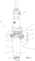
- each retaining head 4 comprises three or more pressure rollers which are distributed eccentrically relative to the secondary axis of rotation 17 of the plate 5.
- the pressure rollers 19 are also configured for pushing with their own lateral surface the container 2 towards the plate 5, in particular during the rotation of the plate 5 on itself.
- the rotation of the pressure rollers 19 occurs about a third axis of rotation 20, which is inclined relative to the secondary axis of rotation 17 in such a way that the lateral surface of the pressure rollers 19, when it is resting on the outer surface of the container 2, applies a thrust with a component which is not null along the secondary axis of rotation 17, towards the plate 5 below.
- the pressure rollers 19 are configured for pressing with their lateral surface on the perimetric zone 11 with axial symmetry of the top wall 10, or on the connecting zone 12 with axial symmetry. Moreover, advantageously, the lateral surface of the pressure rollers 19 is parallel to the relative third axis of rotation 20.
- the pressure rollers 19 are also configured to centre the container 2 on the secondary axis of rotation 17, in particular by making the axial axis of symmetry coincide with the secondary axis of rotation 17.
- the retaining head 4 comprises a supporting portion 21 with which the pressure rollers 19 are rotatably associated.
- the supporting portion 21 has, in plan view, a C shape, with the opening of the C facing radially outwards. The purpose of that arrangement is to allow the passage of a base of the cap 7 of the container 2 through the open part of the C, along a line which is radial relative to the secondary axis of rotation 17.
- the supporting portion 21, and the pressure rollers 19 associated with it can be positioned around the container 2 at an intermediate height between that of the top wall 10 of the containment body 6, and that of the top of the cap 7.
- the nozzle of the cap 7 is therefore positioned above the supporting portion 21 and the rollers.
- housing space 22 may in contrast house a widened part of the cap 7 itself.
- the pressure rollers 19 are associated with the supporting portion 21 above it.
- the third axes of rotation 20, which, as already indicated, are inclined relative to the secondary axis of rotation 17, intersect the secondary axis of rotation 17 and converge towards it moving away from the plate 5. Even more preferably, if the pressure rollers 19 are identical to each other, the third axes of rotation 20 lie on a conical surface centred on the secondary axis of rotation 17, as illustrated in Figure 3 .
- the pressure rollers 19 (or rather, their centres), observed in plan view, are distributed along an arc of a circle centred on the secondary axis of rotation 17. That arc of a circle, which lies in a horizontal plane, defines a concavity facing radially outwards relative to the main axis of rotation 14. Therefore, it reflects the shape of the C-shaped supporting portion 21.
- first end pressure roller 19 whose centre is located at a first end of the arc of a circle
- second end pressure roller 19 whose centre is located at a second end of the arc of a circle
- one or more intermediate pressure rollers 19 whose centres lie along the arc of a circle.
- the arc of a circle preferably extends for an angle ⁇ of between 190° and 210°.
- the pressure rollers 19 are cylindrical, preferably disks with diameter significantly greater than their height.
- the pressure rollers 19 are made of materials which have some elasticity and/or softness, such as rubber.
- the pressure rollers 19 are idle and, in use, rotate as a consequence of the rotation of the container 2 with which they are in contact (which is made to rotate by the plate 5). That does not rule out the fact that in other embodiments at least one of them may be motor-driven and synchronised with the plate 5, or even that the rotation of the container 2 and of the plate 5 may be caused directly using motor-driven pressure rollers 19.
- the retaining head 4 is movable between a raised position and a lowered position.
- the retaining head 4 When it is in the raised position, the retaining head 4 allows the insertion or the removal of a container 2 in or from the space between the insertion head and the plate 5, advantageously without the container 2 making contact with any part of the retaining head 4.
- the axial stroke which corresponds to the shifting of the retaining head 4 between the raised position and the lowered position is a limited stroke, usually of approximately several millimetres/tens of millimetres. Indeed, when the retaining head 4 is located in the raised position, the supporting portion 21 and the pressure rollers 19 must not interfere with the containment body 6 of the container 2 or with the cap 7 during insertion and removal of the container 2.
- the container 2 With the retaining head 4 advantageously in the raised position, the container 2 is positioned on the plate 5. Then the retaining head 4 passes to the lowered position and the pressure rollers 19 rest on the container 2 (on the connecting zone 12 in the accompanying figures). Advantageously the pressure rollers 19 also cause centring of the container 2 on the secondary axis of rotation 17.
- This invention brings important advantages.
- the carrousel apparatus according to this invention allows in particular the best moving of containers with a dosing cap as well as those with high quality or delicate surface finishes.
Landscapes
- Specific Conveyance Elements (AREA)
- Food Preservation Except Freezing, Refrigeration, And Drying (AREA)
- Labeling Devices (AREA)
- Filling Of Jars Or Cans And Processes For Cleaning And Sealing Jars (AREA)
Claims (10)
- Un appareil à carrousel pour déplacer des récipients, comprenant :une structure de support ;un carrousel (13) monté sur la structure de support et pouvant tourner sur lui-même autour d'un axe de rotation principal (14) ; etune pluralité d'unités opérationnelles (16), associées à une portion périmétrique (15) du carrousel (13), pour tourner avec ce dernier autour de l'axe de rotation principal (14), chaque unité opérationnelle (16) étant configurée pour retenir et déplacer un récipient (2), le long d'un parcours de déplacement qui va d'une station d'alimentation de récipients (2) à une station de relâche de récipients (2) ;dans lequel :chaque unité opérationnelle (16) comprend un plateau (5) et une tête de retenue (4) ;chaque plateau (5) est relié de façon rotative au carrousel (13) pour tourner sur lui-même autour de son propre axe de rotation secondaire (17), qui est vertical et parallèle à l'axe de rotation principal (14) ;chaque tête de retenue (4) est verticalement alignée avec le plateau (5) correspondant le long de l'axe de rotation secondaire (17), tourne avec le carrousel (13) lors de la rotation autour de l'axe de rotation principal (14) et est fixe par rapport à l'axe de rotation secondaire (17) du plateau (5) correspondant, pendant la rotation du plateau (5) sur lui-même ;chaque tête de retenue (4) comprend trois ou plus rouleaux de pression (19) répartis excentriquement par rapport à l'axe de rotation secondaire (17) respectif, et configurés pour pousser un récipient (2) vers le plateau (5) pendant la rotation du plateau (5) sur lui-même ; etchaque tête de retenue (4) comprend une portion de support (21) avec laquelle les rouleaux de pression (19) sont associés de façon rotative, chacun selon un troisième axe de rotation (20) ;caractérisé en ce que les troisièmes axes de rotation (20) sont inclinés par rapport à l'axe de rotation secondaire (17), coupent l'axe de rotation secondaire (17) et convergent vers celui-ci en s'éloignant du plateau (5) ; et en ce que les rouleaux de pression (19) de chaque tête de retenue (4) sont configurés pour centrer le récipient (2) sur l'axe de rotation secondaire (17).
- L'appareil à carrousel pour déplacer des récipients (2) selon la revendication 1, dans lequel les troisièmes axes de rotation (20) de chaque tête de retenue (4) reposent sur une surface conique.
- L'appareil à carrousel pour déplacer des récipients (2) selon la revendication 1 ou 2, dans lequel les rouleaux de pression (19) de chaque tête de retenue (4) sont répartis le long d'un arc de cercle centré sur l'axe de rotation secondaire (17), qui repose dans un plan horizontal et qui définit une concavité orientée radialement vers l'extérieur par rapport à l'axe de rotation principal (14), lesdits rouleaux de pression (19) comprenant un premier rouleau de pression (19) d'extrémité dont le centre est situé au niveau d'une première extrémité de l'arc de cercle, un deuxième rouleau de pression (19) d'extrémité dont le centre est situé au niveau d'une deuxième extrémité de l'arc de cercle, et un ou plus rouleaux de pression (19) intermédiaires dont les centres reposent le long de l'arc de cercle.
- L'appareil à carrousel pour déplacer des récipients (2) selon la revendication 3, dans lequel l'arc de cercle s'étend sur un angle compris entre 190° et 210°.
- L'appareil à carrousel pour déplacer des récipients (2) selon l'une quelconque des revendications de 1 à 4, dans lequel la portion de support (21) a une forme en C et dans lequel les rouleaux de pression (19) sont positionnés au-dessus de la portion de support (21).
- L'appareil à carrousel pour déplacer des récipients (2) selon l'une quelconque des revendications de 1 à 5, dans lequel les rouleaux de pression (19) sont cylindriques.
- L'appareil à carrousel pour déplacer des récipients (2) selon l'une quelconque des revendications de 1 à 6, dans lequel les rouleaux de pression (19) sont des rouleaux fous.
- L'appareil à carrousel pour déplacer des récipients (2) selon l'une quelconque des revendications de 1 à 7, dans lequel chaque tête de retenue (4) est mobile entre une position élevée dans laquelle, en utilisation, elle permet l'insertion ou le retrait d'un récipient (2) dans ou de l'espace compris entre la tête d'insertion et le plateau (5), et une position abaissée dans laquelle, en utilisation, les rouleaux de pression (19) sont en appui sur le récipient (2).
- L'appareil à carrousel pour déplacer des récipients (2) selon l'une quelconque des revendications de 1 à 8, dans lequel chaque tête de retenue (4) définit un espace de logement (22) pour un bouchon (7) du récipient (2), au-dessus desdits rouleaux de pression (19).
- L'appareil à carrousel pour déplacer des récipients (2) selon l'une quelconque des revendications de 1 à 9, dans lequel chaque unité opérationnelle (16) est configurée pour déplacer un récipient (2) qui comprend :un corps de confinement (6) inférieur qui a une paroi latérale (8), une paroi de fond (9) raccordée au bas de la paroi latérale (8), et une paroi de dessus (10) raccordée au haut de la paroi latérale (8) et dans laquelle une ouverture est pratiquée ;et un bouchon (7) associé à l'ouverture ;et dans lequel au moins une zone périmétrique (11) de la paroi de dessus (10) ou une zone de raccordement (12) entre la paroi de dessus (10) et la paroi latérale (8) a une symétrie axiale cylindrique par rapport à un axe central vertical du récipient (2) ;dans lequel les rouleaux de pression (19) sont configurés pour exercer une pression avec leur surface latérale sur ladite zone périmétrique (11) ou sur ladite zone de raccordement (12) qui a une symétrie axiale.
Applications Claiming Priority (1)
| Application Number | Priority Date | Filing Date | Title |
|---|---|---|---|
| IT202000008596 | 2020-04-22 |
Publications (2)
| Publication Number | Publication Date |
|---|---|
| EP3901045A1 EP3901045A1 (fr) | 2021-10-27 |
| EP3901045B1 true EP3901045B1 (fr) | 2023-09-27 |
Family
ID=71575569
Family Applications (1)
| Application Number | Title | Priority Date | Filing Date |
|---|---|---|---|
| EP21168978.1A Active EP3901045B1 (fr) | 2020-04-22 | 2021-04-16 | Appareil carrousel pour déplacer des récipients |
Country Status (3)
| Country | Link |
|---|---|
| EP (1) | EP3901045B1 (fr) |
| ES (1) | ES2964009T3 (fr) |
| PT (1) | PT3901045T (fr) |
Family Cites Families (3)
| Publication number | Priority date | Publication date | Assignee | Title |
|---|---|---|---|---|
| DE3341261A1 (de) * | 1983-02-02 | 1984-08-09 | Jagenberg AG, 4000 Düsseldorf | Transportvorrichtung fuer gegenstaende, wie flaschen, insbesondere in einer etikettiermaschine oder sortiermaschine |
| DE3823471A1 (de) * | 1988-07-11 | 1990-01-18 | Anker Maschbau | Etikettiermaschine fuer seiten/deckel-etiketten |
| DE102016207583A1 (de) * | 2016-05-03 | 2017-11-09 | Baumüller Holding GmbH & Co. KG | Behälterbehandlungsmaschine mit einem Drehtellerdirektantrieb |
-
2021
- 2021-04-16 EP EP21168978.1A patent/EP3901045B1/fr active Active
- 2021-04-16 PT PT211689781T patent/PT3901045T/pt unknown
- 2021-04-16 ES ES21168978T patent/ES2964009T3/es active Active
Also Published As
| Publication number | Publication date |
|---|---|
| PT3901045T (pt) | 2023-11-07 |
| EP3901045A1 (fr) | 2021-10-27 |
| ES2964009T3 (es) | 2024-04-03 |
Similar Documents
| Publication | Publication Date | Title |
|---|---|---|
| KR950011147B1 (ko) | 용기위치 결정장치 | |
| EP2473411B1 (fr) | Machine d'étiquetage | |
| US10589889B2 (en) | Labelling machine | |
| EP2133275B1 (fr) | Dispositif d'étiquetage modulaire | |
| US20110233838A1 (en) | Container treatment machine | |
| US4816110A (en) | In-line sealer | |
| US20080283179A1 (en) | Device and Method for Printing Labels | |
| US6439368B1 (en) | Labeling system for container | |
| US11667425B2 (en) | Vacuum drum for a labeling unit, and labeling unit comprising a vacuum drum of this type | |
| CN102574597B (zh) | 用于将至少两个标签粘胶式施加到容器上的单元 | |
| KR20170106336A (ko) | 뚜껑을 용기에 돌려서 조이기 위한 나사 뚜껑, 공구 및 방법 | |
| EP3901045A1 (fr) | Appareil carrousel pour déplacer des récipients | |
| US6973761B2 (en) | Anti-rotation wear plate for capping machine | |
| US20060266479A1 (en) | Beverage bottling plant for filling bottles having non-cylindrical inclined surfaces with a liquid beverage filling material | |
| US4798234A (en) | Can filling system | |
| US5649406A (en) | Positioning apparatus for containers during filling and packaging | |
| US20070028563A1 (en) | Beverage bottling plant for filling beverage bottles with a liquid beverage, with an information adding station for adding information to the beverage bottles, and a method of operating the beverage bottling plant | |
| CN214299184U (zh) | 一种灌装瓶拧盖转瓶机构 | |
| US7406808B1 (en) | Lifter ring rotation control apparatus | |
| CN211996350U (zh) | 一种适用于包装设备的装膜装置 | |
| EP4377240A1 (fr) | Carrousel pour le mouvement de contenants dans des machines d'inspection | |
| CN211770222U (zh) | 全自动液体灌装机 | |
| US20020007919A1 (en) | Labeling machine for containers with non-cylindrical section | |
| JP2019189282A (ja) | ラベラー | |
| US3962970A (en) | Apparatus for supporting and printing non-circular containers |
Legal Events
| Date | Code | Title | Description |
|---|---|---|---|
| PUAI | Public reference made under article 153(3) epc to a published international application that has entered the european phase |
Free format text: ORIGINAL CODE: 0009012 |
|
| STAA | Information on the status of an ep patent application or granted ep patent |
Free format text: STATUS: THE APPLICATION HAS BEEN PUBLISHED |
|
| AK | Designated contracting states |
Kind code of ref document: A1 Designated state(s): AL AT BE BG CH CY CZ DE DK EE ES FI FR GB GR HR HU IE IS IT LI LT LU LV MC MK MT NL NO PL PT RO RS SE SI SK SM TR |
|
| B565 | Issuance of search results under rule 164(2) epc |
Effective date: 20210922 |
|
| STAA | Information on the status of an ep patent application or granted ep patent |
Free format text: STATUS: REQUEST FOR EXAMINATION WAS MADE |
|
| 17P | Request for examination filed |
Effective date: 20211124 |
|
| RBV | Designated contracting states (corrected) |
Designated state(s): AL AT BE BG CH CY CZ DE DK EE ES FI FR GB GR HR HU IE IS IT LI LT LU LV MC MK MT NL NO PL PT RO RS SE SI SK SM TR |
|
| GRAP | Despatch of communication of intention to grant a patent |
Free format text: ORIGINAL CODE: EPIDOSNIGR1 |
|
| STAA | Information on the status of an ep patent application or granted ep patent |
Free format text: STATUS: GRANT OF PATENT IS INTENDED |
|
| RIC1 | Information provided on ipc code assigned before grant |
Ipc: B65C 9/06 20060101ALI20230508BHEP Ipc: B65C 9/04 20060101AFI20230508BHEP |
|
| INTG | Intention to grant announced |
Effective date: 20230524 |
|
| P01 | Opt-out of the competence of the unified patent court (upc) registered |
Effective date: 20230518 |
|
| GRAS | Grant fee paid |
Free format text: ORIGINAL CODE: EPIDOSNIGR3 |
|
| GRAA | (expected) grant |
Free format text: ORIGINAL CODE: 0009210 |
|
| STAA | Information on the status of an ep patent application or granted ep patent |
Free format text: STATUS: THE PATENT HAS BEEN GRANTED |
|
| AK | Designated contracting states |
Kind code of ref document: B1 Designated state(s): AL AT BE BG CH CY CZ DE DK EE ES FI FR GB GR HR HU IE IS IT LI LT LU LV MC MK MT NL NO PL PT RO RS SE SI SK SM TR |
|
| REG | Reference to a national code |
Ref country code: GB Ref legal event code: FG4D |
|
| REG | Reference to a national code |
Ref country code: CH Ref legal event code: EP |
|
| REG | Reference to a national code |
Ref country code: DE Ref legal event code: R096 Ref document number: 602021005361 Country of ref document: DE |
|
| REG | Reference to a national code |
Ref country code: IE Ref legal event code: FG4D |
|
| REG | Reference to a national code |
Ref country code: PT Ref legal event code: SC4A Ref document number: 3901045 Country of ref document: PT Date of ref document: 20231107 Kind code of ref document: T Free format text: AVAILABILITY OF NATIONAL TRANSLATION Effective date: 20231031 |
|
| REG | Reference to a national code |
Ref country code: LT Ref legal event code: MG9D |
|
| PG25 | Lapsed in a contracting state [announced via postgrant information from national office to epo] |
Ref country code: GR Free format text: LAPSE BECAUSE OF FAILURE TO SUBMIT A TRANSLATION OF THE DESCRIPTION OR TO PAY THE FEE WITHIN THE PRESCRIBED TIME-LIMIT Effective date: 20231228 |
|
| PG25 | Lapsed in a contracting state [announced via postgrant information from national office to epo] |
Ref country code: SE Free format text: LAPSE BECAUSE OF FAILURE TO SUBMIT A TRANSLATION OF THE DESCRIPTION OR TO PAY THE FEE WITHIN THE PRESCRIBED TIME-LIMIT Effective date: 20230927 Ref country code: RS Free format text: LAPSE BECAUSE OF FAILURE TO SUBMIT A TRANSLATION OF THE DESCRIPTION OR TO PAY THE FEE WITHIN THE PRESCRIBED TIME-LIMIT Effective date: 20230927 Ref country code: NO Free format text: LAPSE BECAUSE OF FAILURE TO SUBMIT A TRANSLATION OF THE DESCRIPTION OR TO PAY THE FEE WITHIN THE PRESCRIBED TIME-LIMIT Effective date: 20231227 Ref country code: LV Free format text: LAPSE BECAUSE OF FAILURE TO SUBMIT A TRANSLATION OF THE DESCRIPTION OR TO PAY THE FEE WITHIN THE PRESCRIBED TIME-LIMIT Effective date: 20230927 Ref country code: LT Free format text: LAPSE BECAUSE OF FAILURE TO SUBMIT A TRANSLATION OF THE DESCRIPTION OR TO PAY THE FEE WITHIN THE PRESCRIBED TIME-LIMIT Effective date: 20230927 Ref country code: HR Free format text: LAPSE BECAUSE OF FAILURE TO SUBMIT A TRANSLATION OF THE DESCRIPTION OR TO PAY THE FEE WITHIN THE PRESCRIBED TIME-LIMIT Effective date: 20230927 Ref country code: GR Free format text: LAPSE BECAUSE OF FAILURE TO SUBMIT A TRANSLATION OF THE DESCRIPTION OR TO PAY THE FEE WITHIN THE PRESCRIBED TIME-LIMIT Effective date: 20231228 Ref country code: FI Free format text: LAPSE BECAUSE OF FAILURE TO SUBMIT A TRANSLATION OF THE DESCRIPTION OR TO PAY THE FEE WITHIN THE PRESCRIBED TIME-LIMIT Effective date: 20230927 |
|
| REG | Reference to a national code |
Ref country code: NL Ref legal event code: MP Effective date: 20230927 |
|
| REG | Reference to a national code |
Ref country code: AT Ref legal event code: MK05 Ref document number: 1615211 Country of ref document: AT Kind code of ref document: T Effective date: 20230927 |
|
| PG25 | Lapsed in a contracting state [announced via postgrant information from national office to epo] |
Ref country code: NL Free format text: LAPSE BECAUSE OF FAILURE TO SUBMIT A TRANSLATION OF THE DESCRIPTION OR TO PAY THE FEE WITHIN THE PRESCRIBED TIME-LIMIT Effective date: 20230927 |
|
| REG | Reference to a national code |
Ref country code: ES Ref legal event code: FG2A Ref document number: 2964009 Country of ref document: ES Kind code of ref document: T3 Effective date: 20240403 |
|
| PG25 | Lapsed in a contracting state [announced via postgrant information from national office to epo] |
Ref country code: IS Free format text: LAPSE BECAUSE OF FAILURE TO SUBMIT A TRANSLATION OF THE DESCRIPTION OR TO PAY THE FEE WITHIN THE PRESCRIBED TIME-LIMIT Effective date: 20240127 |
|
| PG25 | Lapsed in a contracting state [announced via postgrant information from national office to epo] |
Ref country code: AT Free format text: LAPSE BECAUSE OF FAILURE TO SUBMIT A TRANSLATION OF THE DESCRIPTION OR TO PAY THE FEE WITHIN THE PRESCRIBED TIME-LIMIT Effective date: 20230927 |
|
| PG25 | Lapsed in a contracting state [announced via postgrant information from national office to epo] |
Ref country code: SM Free format text: LAPSE BECAUSE OF FAILURE TO SUBMIT A TRANSLATION OF THE DESCRIPTION OR TO PAY THE FEE WITHIN THE PRESCRIBED TIME-LIMIT Effective date: 20230927 Ref country code: RO Free format text: LAPSE BECAUSE OF FAILURE TO SUBMIT A TRANSLATION OF THE DESCRIPTION OR TO PAY THE FEE WITHIN THE PRESCRIBED TIME-LIMIT Effective date: 20230927 Ref country code: IS Free format text: LAPSE BECAUSE OF FAILURE TO SUBMIT A TRANSLATION OF THE DESCRIPTION OR TO PAY THE FEE WITHIN THE PRESCRIBED TIME-LIMIT Effective date: 20240127 Ref country code: EE Free format text: LAPSE BECAUSE OF FAILURE TO SUBMIT A TRANSLATION OF THE DESCRIPTION OR TO PAY THE FEE WITHIN THE PRESCRIBED TIME-LIMIT Effective date: 20230927 Ref country code: CZ Free format text: LAPSE BECAUSE OF FAILURE TO SUBMIT A TRANSLATION OF THE DESCRIPTION OR TO PAY THE FEE WITHIN THE PRESCRIBED TIME-LIMIT Effective date: 20230927 Ref country code: AT Free format text: LAPSE BECAUSE OF FAILURE TO SUBMIT A TRANSLATION OF THE DESCRIPTION OR TO PAY THE FEE WITHIN THE PRESCRIBED TIME-LIMIT Effective date: 20230927 Ref country code: SK Free format text: LAPSE BECAUSE OF FAILURE TO SUBMIT A TRANSLATION OF THE DESCRIPTION OR TO PAY THE FEE WITHIN THE PRESCRIBED TIME-LIMIT Effective date: 20230927 |
|
| PG25 | Lapsed in a contracting state [announced via postgrant information from national office to epo] |
Ref country code: PL Free format text: LAPSE BECAUSE OF FAILURE TO SUBMIT A TRANSLATION OF THE DESCRIPTION OR TO PAY THE FEE WITHIN THE PRESCRIBED TIME-LIMIT Effective date: 20230927 |
|
| REG | Reference to a national code |
Ref country code: DE Ref legal event code: R097 Ref document number: 602021005361 Country of ref document: DE |
|
| PG25 | Lapsed in a contracting state [announced via postgrant information from national office to epo] |
Ref country code: DK Free format text: LAPSE BECAUSE OF FAILURE TO SUBMIT A TRANSLATION OF THE DESCRIPTION OR TO PAY THE FEE WITHIN THE PRESCRIBED TIME-LIMIT Effective date: 20230927 |
|
| PG25 | Lapsed in a contracting state [announced via postgrant information from national office to epo] |
Ref country code: DK Free format text: LAPSE BECAUSE OF FAILURE TO SUBMIT A TRANSLATION OF THE DESCRIPTION OR TO PAY THE FEE WITHIN THE PRESCRIBED TIME-LIMIT Effective date: 20230927 |
|
| PLBE | No opposition filed within time limit |
Free format text: ORIGINAL CODE: 0009261 |
|
| STAA | Information on the status of an ep patent application or granted ep patent |
Free format text: STATUS: NO OPPOSITION FILED WITHIN TIME LIMIT |
|
| 26N | No opposition filed |
Effective date: 20240628 |
|
| PG25 | Lapsed in a contracting state [announced via postgrant information from national office to epo] |
Ref country code: SI Free format text: LAPSE BECAUSE OF FAILURE TO SUBMIT A TRANSLATION OF THE DESCRIPTION OR TO PAY THE FEE WITHIN THE PRESCRIBED TIME-LIMIT Effective date: 20230927 |
|
| PG25 | Lapsed in a contracting state [announced via postgrant information from national office to epo] |
Ref country code: SI Free format text: LAPSE BECAUSE OF FAILURE TO SUBMIT A TRANSLATION OF THE DESCRIPTION OR TO PAY THE FEE WITHIN THE PRESCRIBED TIME-LIMIT Effective date: 20230927 |
|
| PG25 | Lapsed in a contracting state [announced via postgrant information from national office to epo] |
Ref country code: BG Free format text: LAPSE BECAUSE OF FAILURE TO SUBMIT A TRANSLATION OF THE DESCRIPTION OR TO PAY THE FEE WITHIN THE PRESCRIBED TIME-LIMIT Effective date: 20230927 |
|
| PG25 | Lapsed in a contracting state [announced via postgrant information from national office to epo] |
Ref country code: MC Free format text: LAPSE BECAUSE OF FAILURE TO SUBMIT A TRANSLATION OF THE DESCRIPTION OR TO PAY THE FEE WITHIN THE PRESCRIBED TIME-LIMIT Effective date: 20230927 |
|
| PG25 | Lapsed in a contracting state [announced via postgrant information from national office to epo] |
Ref country code: MC Free format text: LAPSE BECAUSE OF FAILURE TO SUBMIT A TRANSLATION OF THE DESCRIPTION OR TO PAY THE FEE WITHIN THE PRESCRIBED TIME-LIMIT Effective date: 20230927 Ref country code: BG Free format text: LAPSE BECAUSE OF FAILURE TO SUBMIT A TRANSLATION OF THE DESCRIPTION OR TO PAY THE FEE WITHIN THE PRESCRIBED TIME-LIMIT Effective date: 20230927 |
|
| REG | Reference to a national code |
Ref country code: CH Ref legal event code: PL |
|
| PG25 | Lapsed in a contracting state [announced via postgrant information from national office to epo] |
Ref country code: LU Free format text: LAPSE BECAUSE OF NON-PAYMENT OF DUE FEES Effective date: 20240416 |
|
| PG25 | Lapsed in a contracting state [announced via postgrant information from national office to epo] |
Ref country code: LU Free format text: LAPSE BECAUSE OF NON-PAYMENT OF DUE FEES Effective date: 20240416 |
|
| PG25 | Lapsed in a contracting state [announced via postgrant information from national office to epo] |
Ref country code: CH Free format text: LAPSE BECAUSE OF NON-PAYMENT OF DUE FEES Effective date: 20240430 |
|
| PG25 | Lapsed in a contracting state [announced via postgrant information from national office to epo] |
Ref country code: IE Free format text: LAPSE BECAUSE OF NON-PAYMENT OF DUE FEES Effective date: 20240416 |
|
| PGFP | Annual fee paid to national office [announced via postgrant information from national office to epo] |
Ref country code: DE Payment date: 20250428 Year of fee payment: 5 |
|
| PGFP | Annual fee paid to national office [announced via postgrant information from national office to epo] |
Ref country code: ES Payment date: 20250513 Year of fee payment: 5 |
|
| PGFP | Annual fee paid to national office [announced via postgrant information from national office to epo] |
Ref country code: BE Payment date: 20250424 Year of fee payment: 5 Ref country code: IT Payment date: 20250422 Year of fee payment: 5 |
|
| PGFP | Annual fee paid to national office [announced via postgrant information from national office to epo] |
Ref country code: FR Payment date: 20250424 Year of fee payment: 5 |
|
| PG25 | Lapsed in a contracting state [announced via postgrant information from national office to epo] |
Ref country code: CY Free format text: LAPSE BECAUSE OF FAILURE TO SUBMIT A TRANSLATION OF THE DESCRIPTION OR TO PAY THE FEE WITHIN THE PRESCRIBED TIME-LIMIT; INVALID AB INITIO Effective date: 20210416 |
|
| PG25 | Lapsed in a contracting state [announced via postgrant information from national office to epo] |
Ref country code: HU Free format text: LAPSE BECAUSE OF FAILURE TO SUBMIT A TRANSLATION OF THE DESCRIPTION OR TO PAY THE FEE WITHIN THE PRESCRIBED TIME-LIMIT; INVALID AB INITIO Effective date: 20210416 |
|
| PGFP | Annual fee paid to national office [announced via postgrant information from national office to epo] |
Ref country code: GB Payment date: 20260304 Year of fee payment: 6 |
|
| PGFP | Annual fee paid to national office [announced via postgrant information from national office to epo] |
Ref country code: PT Payment date: 20260326 Year of fee payment: 6 |