EP3901074B1 - Dispositif de transport pour une pile de boîtes pliantes, et procédé correspondant pour transporter des piles de boîtes pliantes - Google Patents
Dispositif de transport pour une pile de boîtes pliantes, et procédé correspondant pour transporter des piles de boîtes pliantes Download PDFInfo
- Publication number
- EP3901074B1 EP3901074B1 EP20214678.3A EP20214678A EP3901074B1 EP 3901074 B1 EP3901074 B1 EP 3901074B1 EP 20214678 A EP20214678 A EP 20214678A EP 3901074 B1 EP3901074 B1 EP 3901074B1
- Authority
- EP
- European Patent Office
- Prior art keywords
- slider
- stack
- movement
- carriage
- linear guide
- Prior art date
- Legal status (The legal status is an assumption and is not a legal conclusion. Google has not performed a legal analysis and makes no representation as to the accuracy of the status listed.)
- Active
Links
Images


Classifications
-
- B—PERFORMING OPERATIONS; TRANSPORTING
- B65—CONVEYING; PACKING; STORING; HANDLING THIN OR FILAMENTARY MATERIAL
- B65H—HANDLING THIN OR FILAMENTARY MATERIAL, e.g. SHEETS, WEBS, CABLES
- B65H31/00—Pile receivers
- B65H31/30—Arrangements for removing completed piles
- B65H31/3081—Arrangements for removing completed piles by acting on edge of the pile for moving it along a surface, e.g. by pushing
-
- B—PERFORMING OPERATIONS; TRANSPORTING
- B65—CONVEYING; PACKING; STORING; HANDLING THIN OR FILAMENTARY MATERIAL
- B65G—TRANSPORT OR STORAGE DEVICES, e.g. CONVEYORS FOR LOADING OR TIPPING, SHOP CONVEYOR SYSTEMS OR PNEUMATIC TUBE CONVEYORS
- B65G25/00—Conveyors comprising a cyclically-moving, e.g. reciprocating, carrier or impeller which is disengaged from the load during the return part of its movement
- B65G25/02—Conveyors comprising a cyclically-moving, e.g. reciprocating, carrier or impeller which is disengaged from the load during the return part of its movement the carrier or impeller having different forward and return paths of movement, e.g. walking beam conveyors
-
- B—PERFORMING OPERATIONS; TRANSPORTING
- B65—CONVEYING; PACKING; STORING; HANDLING THIN OR FILAMENTARY MATERIAL
- B65H—HANDLING THIN OR FILAMENTARY MATERIAL, e.g. SHEETS, WEBS, CABLES
- B65H31/00—Pile receivers
- B65H31/02—Pile receivers with stationary end support against which pile accumulates
-
- B—PERFORMING OPERATIONS; TRANSPORTING
- B65—CONVEYING; PACKING; STORING; HANDLING THIN OR FILAMENTARY MATERIAL
- B65H—HANDLING THIN OR FILAMENTARY MATERIAL, e.g. SHEETS, WEBS, CABLES
- B65H31/00—Pile receivers
- B65H31/20—Pile receivers adjustable for different article sizes
-
- B—PERFORMING OPERATIONS; TRANSPORTING
- B65—CONVEYING; PACKING; STORING; HANDLING THIN OR FILAMENTARY MATERIAL
- B65H—HANDLING THIN OR FILAMENTARY MATERIAL, e.g. SHEETS, WEBS, CABLES
- B65H2301/00—Handling processes for sheets or webs
- B65H2301/40—Type of handling process
- B65H2301/42—Piling, depiling, handling piles
- B65H2301/421—Forming a pile
- B65H2301/4212—Forming a pile of articles substantially horizontal
-
- B—PERFORMING OPERATIONS; TRANSPORTING
- B65—CONVEYING; PACKING; STORING; HANDLING THIN OR FILAMENTARY MATERIAL
- B65H—HANDLING THIN OR FILAMENTARY MATERIAL, e.g. SHEETS, WEBS, CABLES
- B65H2404/00—Parts for transporting or guiding the handled material
- B65H2404/70—Other elements in edge contact with handled material, e.g. registering, orientating, guiding devices
- B65H2404/73—Means for sliding the handled material on a surface, e.g. pushers
- B65H2404/731—Means for sliding the handled material on a surface, e.g. pushers moved in a path enclosing an area
-
- B—PERFORMING OPERATIONS; TRANSPORTING
- B65—CONVEYING; PACKING; STORING; HANDLING THIN OR FILAMENTARY MATERIAL
- B65H—HANDLING THIN OR FILAMENTARY MATERIAL, e.g. SHEETS, WEBS, CABLES
- B65H2405/00—Parts for holding the handled material
- B65H2405/10—Cassettes, holders, bins, decks, trays, supports or magazines for sheets stacked substantially horizontally
- B65H2405/11—Parts and details thereof
- B65H2405/112—Rear, i.e. portion opposite to the feeding / delivering side
- B65H2405/1122—Rear, i.e. portion opposite to the feeding / delivering side movable linearly, details therefor
-
- B—PERFORMING OPERATIONS; TRANSPORTING
- B65—CONVEYING; PACKING; STORING; HANDLING THIN OR FILAMENTARY MATERIAL
- B65H—HANDLING THIN OR FILAMENTARY MATERIAL, e.g. SHEETS, WEBS, CABLES
- B65H2511/00—Dimensions; Position; Numbers; Identification; Occurrences
- B65H2511/10—Size; Dimensions
- B65H2511/11—Length
-
- B—PERFORMING OPERATIONS; TRANSPORTING
- B65—CONVEYING; PACKING; STORING; HANDLING THIN OR FILAMENTARY MATERIAL
- B65H—HANDLING THIN OR FILAMENTARY MATERIAL, e.g. SHEETS, WEBS, CABLES
- B65H2511/00—Dimensions; Position; Numbers; Identification; Occurrences
- B65H2511/10—Size; Dimensions
- B65H2511/15—Height, e.g. of stack
-
- B—PERFORMING OPERATIONS; TRANSPORTING
- B65—CONVEYING; PACKING; STORING; HANDLING THIN OR FILAMENTARY MATERIAL
- B65H—HANDLING THIN OR FILAMENTARY MATERIAL, e.g. SHEETS, WEBS, CABLES
- B65H2511/00—Dimensions; Position; Numbers; Identification; Occurrences
- B65H2511/20—Location in space
-
- B—PERFORMING OPERATIONS; TRANSPORTING
- B65—CONVEYING; PACKING; STORING; HANDLING THIN OR FILAMENTARY MATERIAL
- B65H—HANDLING THIN OR FILAMENTARY MATERIAL, e.g. SHEETS, WEBS, CABLES
- B65H2701/00—Handled material; Storage means
- B65H2701/10—Handled articles or webs
- B65H2701/17—Nature of material
- B65H2701/176—Cardboard
- B65H2701/1766—Cut-out, multi-layer, e.g. folded blanks or boxes
Definitions
- a stack of finished folding boxes is formed in a so-called shaft module.
- the shaft module in simple terms, comprises a buffer space into which the finished folding boxes flow from a stream of folding boxes.
- a movable stop in the buffer area. The folding boxes flowing into the buffer area hit the stop and are thereby positioned or aligned.
- this stack is transported out of the shaft module and pushed into the working area of an adjoining device for bundling (hereinafter referred to as the bundling device). Immediately afterwards, the next stack is formed in the buffer area.
- the invention relates to a device for transporting a stack of folding boxes, which can preferably be used at the transition between the shaft module and the bundling device.
- a special feature of modern bundling devices must be taken into account:
- the bundling devices usually have a stylus that - viewed in the direction of transport - moves vertically down behind the stack of folding boxes in order to guide the strapping band around the stack.
- the stack of folding boxes must therefore be pushed with its rear edge far enough into the working area of the bundling device in the direction of transport that the stylus can move down behind the stack from above.
- Transport devices are known from the state of the art in which a pusher pushes the stack out of the Stacking space into the working space of the bundling device.
- the pusher is located behind the stack.
- the drive of the pusher is activated so that the pusher transports the stack into the working space of the bundling device.
- the pusher then moves back to its starting position in the buffer space.
- the slider In order to prevent the slider from colliding with the stack that is being created in the buffer space of the shaft module, the slider must descend far enough during the return movement to pass under the stack and return to its starting position.
- the slider In the transport devices available on the market, the slider is guided by a closed chain that is redirected several times over several sprockets (hereinafter referred to as the chain strand).
- the position of the sprockets cannot be changed and determines the movement of the slider when transporting the stack (transport movement) and during the subsequent return movement.
- These devices have several disadvantages: The movement of the slider is fixed by the arrangement of the sprockets both when transporting the stack and when the slider returns to the starting position.
- the transport path of the slider is dimensioned so that it can push a stack of folding boxes with maximum dimensions out of the shaft module into the bundling device. If, for example, folding boxes are stacked whose length is only half the maximum possible length of the folding boxes, then the pusher has to carry out the same transport path. In other words: half of the transport movement is "unproductive". Of course, the return movement of the pusher then also takes longer than necessary. Both effects reduce the transport capacity.
- the invention is based on the object of providing a transport device for a stack of folding boxes or other goods stacked on top of one another, which avoids the disadvantages of the prior art. It should be more flexible in terms of its transport movement and its return movement and, in addition, with all other conditions being the same, the capacity or output of the transport device should be increased.
- a device for transporting a stack of folding boxes comprising a support for the stack of folding boxes and at least one slider, wherein the at least one slider protrudes beyond the support in the vertical direction during the transport movement and at least part of its return movement takes place in such a way that the slider does not protrude beyond the support, in that the at least one slider is attached to a first carriage of a first linear guide and that a first guide rail of the first linear guide is fastened to a second carriage of a second linear guide.
- the claimed invention therefore breaks away from the known guide of the slider by a chain run, but instead provides two linear guides that are usually arranged at right angles to each other. These linear guides enable a free configuration of the transport movement and the return movement. For example, if short stacks of folding boxes are to be transported, the Transport path can be shortened. This eliminates the above-mentioned "dead times" during the transport movement. Because the return movement is always only as long as the transport movement, the return movement is also shortened. Because the outward and return path are shortened, the cycle time for a transport process is also reduced. As a result, the output or conveying capacity of the transport device according to the invention is significantly increased.
- a further advantage of the transport device according to the invention is that the slider carries out a straight movement until the end of the transport movement, which generally runs parallel to the support for the stack.
- the height of the slider in relation to the support does not change during the transport movement; the "diving" of the slider at the end of the transport movement, which is common in the prior art, does not occur.
- the slider must descend downwards during the return movement so that it can pass under the next stack that forms in the buffer space and reach the starting position without colliding with the next stack.
- the return movement therefore requires a coordinated movement of the slider on the first and second linear guides or the associated drives.
- the first linear guide causes the slider to "dive" during the return movement in accordance with the requirements and dimensions of the stacks to be transported.
- the dive is designed so that the slider moves downwards (dives) quickly enough that it does not collide with the stack that is forming in the buffer space of the shaft module during the return movement.
- the front edge of this stack that is forming is the point at risk of collision.
- the slider's dive movement can be adjusted before or during the return movements in accordance with the dimensions and position of the stack in the buffer space.
- the height of the slider above the support can also be adjusted to the height of the stack to be transported.
- the slider protrudes less far above the support of the stack during the transport movement.
- the downward movement at the beginning of the return movement and the upward movement at the end of the return movement are correspondingly shortened. Both effects reduce the loads on the drives and linear guides and increase the transport capacity.
- a third linear guide is provided parallel to the second linear guide which carries out the transport movement.
- the first guide rail of the first linear guide is additionally attached to a third carriage of the third linear guide.
- the transport device has a first drive for moving the first carriage on the first guide rail.
- a further advantageous embodiment provides for a second drive for moving the second carriage on the second guide rail of the second linear guide and the optional third carriage on the optional third guide rail of the third linear guide.
- the first drive and/or the second drive can have a servo motor, a stepper motor or a linear motor.
- a servo motor means that, regardless of the load, the position of the first slide and the second slide is known. This makes it possible to compare the actual position of the slide with a target position in a closed control loop. This means that almost any desired movement of the slide can be realized with high repeatability. The same applies if a linear motor or a stepper motor is used.
- a servo motor or a stepper motor can be connected to the first slide or the second slide via a toothed belt, a chain or a threaded spindle. This makes it possible, in a known manner, to convert the rotary movement of the servo motor or the stepper motor into a linear movement of the first or second slide and the optional third slide. As a result, the slider experiences the transport and return movement that can be freely configured and optimized for each application.
- the first drive and the second drive are preferably connected to a controller or a control and/or regulating device which, based on a predetermined target movement, controls and regulates the first drive and the second drive in such a way that the slide executes the desired target movement.
- control or regulation of the position of the first carriage and the control or regulation of the position of the second carriage are usually carried out independently of each other. It is also possible to provide a separate controller for each drive.
- the transport movement of the slider is best realized when a longitudinal axis of the second linear guide and the optional third linear guide runs parallel to the support.
- the return movement of the slider and in particular the descent of the slider at the beginning of the return movement and the subsequent emergence of the slider at the end of the return movement can be best realized if the longitudinal axis of the first linear guide runs orthogonal to the support or the longitudinal axis of the support.
- the first linear guide and the second linear guide span a plane of two axes.
- the longitudinal axis of the second and third linear guide is referred to as the X-axis and the longitudinal direction of the first linear guide is referred to as the Y-axis.
- a movable stop is provided at the rear end of the buffer space (seen in the direction of transport). This movable stop has a direction of movement parallel to the Y-axis, i.e. it can be moved upwards out of the buffer space of the shaft module.
- This movement is carried out by an electric drive, in the invention by a linear motor, a stepper motor or a servo motor.
- These drives have, as already mentioned in connection with the drives for the slide, the positive property that the position of the stop is known at any time. The stop therefore only has to be moved upwards so far that its lower end is slightly is positioned higher than the top of the stack. It is then possible to start the transport movement without risking a collision with the stop. This has advantages when processing or transporting low stacks of folding boxes because the transport movement can start earlier.
- Pneumatically movable stops are known from the state of the art. With these pneumatically movable stops, the position of the stop is not known. It is therefore detected via end stops, so that the travel path of the end stop must always be as large as the height of the largest stack that can be formed in the shaft module, regardless of the actual height of the stack.
- the stop can remain in this position until the stack has been pushed out from under it. The stop then moves back down to its original position. This path also only takes about half the time because, as in the example mentioned, the stop has only travelled half the distance. This is also an effective measure for increasing the output of the transport device according to the invention.
- the object underlying the invention is achieved even better if two slides, two first linear guides, two second linear guides as well as two first drives and two second drives are designed in a transport device.
- These pushers can be moved individually and independently of each other. With this transport device, it is possible to use the first pusher and the second pusher alternately at different times, so that for a first stack, the first pusher takes over the transport movement. Meanwhile, the second pusher makes the reverse movement and moves to the starting position. As soon as a second stack has been completely stacked in the shaft module, the second pusher begins to push this second stack into the bundling device. Meanwhile, the first pusher, which is at the end of the transport path, dives downwards and dives under the second stack towards the starting position. It then transports the third stack.
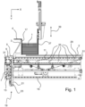
- Two axes are shown, namely an X-axis and a Y-axis.
- the X-axis runs in the direction of the transport movement of stack 1.
- the Y-axis runs perpendicular to this.
- the "diving movement" of slider 3 already mentioned several times, runs in the direction of the positive Y-axis.
- Stack 1 is shown in its "starting position" in the buffer space of the shaft module. Stack 1 rests on a support 2. Support 2 is stationary, ie it does not follow the movement of carriage 3.
- the transport of stack 1 takes place in the Figure 1 to the right into the working area of a bundling device (not shown).
- a slider 3 is driven and its movement is transferred to the stack 1.
- the slider 3 is positioned so that it lies behind the stack 1 in the transport direction (positive X-axis), i.e., so to speak, on the back of the stack 1.
- the slide 3 is attached to a first carriage 5 of a first linear guide.
- the first carriage 5 forms together with a first guide rail 7, the first linear guide.
- the alignment of the first guide rail is parallel to the Y-axis and perpendicular to the X-axis.
- the first guide rail 7 is arranged on a second carriage 9 of a second linear guide.
- the second linear guide includes a second guide rail 11, which is arranged parallel to the X-axis.
- the first guide rail 7 is also attached to an optional third carriage 13 of a third linear guide.
- the third carriage 13 or the third linear guide includes a third guide rail 15.
- the second guide rail 11 and the third guide rail 15 run parallel to each other in the X direction.
- the third linear guide serves to improve the guidance of the slider 3 so that the slider 3 can transfer the drive forces required to transport the stack 1 to the stack 1 in the direction of the X axis without deviating backwards.
- the slider 3 is designed in such a way that its attachment point on the first carriage 5 and its front edge 17 are offset from each other. This allows the slider 3 to push the stack 1 far beyond the end of the support 2 and the second and third guide rails 11 and 15 (to the right into the Figures 1 - 5 ) into the working area of the bundling device (not shown).
- a first drive 19 is indicated, which moves the first carriage 5 on the first guide rail 7 in the direction of the Y-axis.
- the first drive 19 comprises a toothed belt 21, several toothed pulleys 23, of which in the Figure 1 only one is visible, and an electric drive, for example in the form of a servo motor or a stepper motor.
- the electric drive and a control and/or regulating device for controlling the drives are in the Figure 1 not shown.
- the servo motor drives one of the toothed pulleys 23. This in turn drives the toothed belt 21. Since the first carriage 5 is connected to the toothed belt 21, the first carriage 5 and with it the slide 3 are moved in the direction of the Y axis.
- the functionality of such a linear drive and the necessary control by a control and/or regulating device are known to the relevant expert from other applications and therefore do not require any further explanation.
- FIG. 1 Two embodiments of a second drive are shown. Firstly, a linear motor is shown. A stator 25 of the linear motor is shown in the Figure 1 The counterpart of the stator, the rotor of the linear motor, is in the Figure 1 not visible. Rather, it is largely concealed by the first carriage 5 and the toothed belt 21.
- Figure 1 a second embodiment of a second drive according to the invention is shown. It is constructed in the same way as the first drive: It comprises a toothed belt 29, toothed disks 31 and an electric drive. The electric drive is again not visible here. In this respect, what was said in connection with the first drive 19 applies accordingly.
- a fixed stacking wall 4 is provided at the rear end of the buffer space in the transport direction.
- a movable stop 37 is shown at the front end of the buffer space in the transport direction.
- the movable stop 37 is the Figure 1 in its lower end position. It can be moved back and forth between this lower end position and an upper end position. These movements run parallel to the Y-axis and are indicated by a double arrow 39.
- the movable stop 37 according to the invention is equipped with an electric drive.
- the drive can be designed as an electric linear drive or similar to the drives of the slides 5 and 9. It is preferred if the position of the stop 37 in the control and/or regulating device is also known by controlling the drive or by position sensors (not shown).
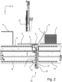
- the slider 3 has reached the end of the transport path.
- the figure shows a "new" stack 1 being built up. This stack 1 rests with its front side against the slide 37, which is now back in the lower end position. This new stack 1 is created while the previous stack is being transported into the working area of the bundling device.
- the descent during the return movement is necessary so that the slider 3 can reach the starting position under the support 2 and the "new" stack 1 of folding boxes 33 that is being formed at this time.
- the movement of the folding boxes 33 into the buffer space of the shaft module is indicated by an arrow 35.
- the individual folding boxes 33 are conveyed along the direction of movement indicated by the arrow 35 into the buffer space of the shaft module in a manner known per se.
- the movable stop 37 is located at the rear end of the buffer space in the direction of movement.
- Figure 4 in its lower end position. It can be moved back and forth between this lower end position and an upper end position (see the double arrow 39).
- the movable stop 37 is moved upwards out of the buffer space so far that it no longer hinders the transport movement of the stack 1. As soon as the lower end of the movable stop 37 is higher than the upper edge of the stack 1, the transport movement in the direction of the positive X-axis can begin.
- the movable stop 37 only has to travel half the way up to clear the way for the stack 1. It is sufficient if the lower end of the movable stop 37 is slightly higher than the upper edge of the stack 1. With a less high stack 1, the travel path of the movable stop 37 is correspondingly shorter, so that time is saved for the movement of the stop 37 both when moving upwards and when moving in the opposite direction. Since the control and/or regulating device knows the position of the stop 37, the transport movement of the stack 1 can be started immediately after the movable stop 37 has moved so far up that there can no longer be a collision between stop 37 and stack 1 or slide 3. This further increases the output of the transport device according to the invention.
- FIG 6 is a front view of the Figures 1 to 5
- the embodiment shown is shown in a highly simplified manner.
- the viewing direction is from the working area of the bundling device to the stack 1, ie the viewing direction runs in the direction of the negative X-axis.
- the components of the first guide namely the first carriage 5 and the first linear guide 7, the second linear guide, namely the second carriage 9 and the second guide rail 11 and the third linear guide, namely the third carriage 13 and the third guide rail 15 are shown in the Figure 6
- the electric drives for the first carriage 5 and the second carriage 9 are shown in the Figure 6 and 7 not shown.
- FIG 7 A further embodiment of a transport device according to the invention is shown.
- slide 3 first linear guide, second linear guide and third linear guide are present twice.
- the device is constructed mirror-symmetrically. The runs perpendicular to the plane of the drawing. Therefore, the Figure 7 which in itself consists of Figures 1 to 6 known components are each provided with the index R or L to illustrate the equality of the components and the duplicate presence of the mentioned components.
- the two transport devices or the two slides 3R and 3L are not offset from each other in the direction of the Z axis, but are arranged in the same plane.
- the reason why there are no collisions between the two sliders 3R and 31 is that they move at different heights (i.e. different Y values) during the transport movement and during the return movements.
- Sliders 3R and 3L work alternately. Slider 3R is behind stack 1 and is carrying out a transport movement, while slider 3L is moving back. Therefore, slider 3L has descended downwards in the direction of the positive Y axis. It has not yet descended completely. If it has descended far enough to pass under the approaching stack 1 to its starting position, a collision is ruled out.
- the tip 43 of the slider 3 is shown in the starting position.
- the tip of the slider 43 moves along the horizontal line from the starting position I to the end point II.
- the transport movement between the starting position I and the end point II is indicated by a line 45.
- a first "dive curve” is shown in the form of a trajectory 47, in which the tip 43 of the slider 3 and with it the entire slider 3 dives relatively quickly and steeply downwards.
- the slider or the tip 43 has reached the lowest point and can thus dive under an oncoming stack 1, ie a stack that moves on the shelf 2 in the direction of the positive X-axis.
- This situation is shown in the Figures 4 and 5 shown. If the stack 1 (not shown) is shorter, then the slider 3 does not have to descend so steeply; it can perform a gentler descent movement 49 that requires less drive power. As a result, the slider 3 reaches the lowest point, which is marked III', later in space and usually also later in time.
- the end of the return movement is at IV.
- the slider 3 is vertical, ie parallel to the Y-axis, or almost vertically along the trajectory 53 upwards to the starting position I. This steep ascent movement is necessary because the slider 3 as in Figure 5 shown must appear more or less vertically behind the new stack 1 that is being built up.
- Trajectories 47 and 49 are shown only as examples. All intermediate forms are possible between them. However, even more extreme trajectories are also possible.
- the design of the trajectories offers considerable optimization potential in order to relieve the load on the drives and still safely prevent a collision of the pusher 3 during its return movement with a stack 1 that is either just forming in the starting position or a stack of folding boxes that is already being transported (see Figure 7 ).
- This optimization potential can be utilized with the aid of the device and the method according to the invention, so that the output can be increased without necessarily increasing the load on the individual components and their wear.
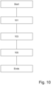
- the main dimensions (length, height and, if applicable, width) are entered in a block 101.
- start position (I or I') and the end position (II or II') are determined depending on the length of the stack (1).
- the descent movement (from II or II' to III or III') and the ascent movement (from IV to I) are determined depending on the height of the stack (1).
- the return movement is determined on the basis of these partial movements.
Landscapes
- Engineering & Computer Science (AREA)
- Mechanical Engineering (AREA)
- Pile Receivers (AREA)
- Basic Packing Technique (AREA)
Claims (13)
- Dispositif de transport d'une pile (1) de boîtes pliantes, comprenant un support (2) pour la pile (1) de boîtes pliantes et au moins un coulisseau (3), dans lequel l'au moins un coulisseau (3) dépasse du support (2) lors d'un déplacement de transport dans une direction verticale et au moins une partie d'un déplacement de retour est effectuée de telle sorte que l'au moins un coulisseau (3) ne dépasse pas du support (2), dans lequel l'au moins un coulisseau (3) est installé sur un premier chariot (5) d'une première glissière linéaire, caractérisé en ce qu'un premier rail de guidage (7) de la première glissière linéaire est fixé sur un deuxième chariot (9) d'une deuxième glissière linéaire.
- Dispositif selon la revendication 1, caractérisé en ce qu'est prévue une troisième glissière linéaire de manière parallèle à la deuxième glissière linéaire, et que le premier rail de guidage (7) de la première glissière linéaire est fié également sur un troisième chariot (13) de la troisième glissière linéaire.
- Dispositif selon la revendication 1 ou 2, caractérisé en ce qu'il présente un premier entraînement destiné à déplacer le premier chariot (4) sur le premier rail de guidage (7).
- Dispositif selon l'une quelconque des revendications précédentes, caractérisé en ce qu'il présente un deuxième entraînement pour déplacer le deuxième chariot (9) sur le deuxième rail de guidage (11) de la deuxième glissière linéaire et le troisième chariot (13) optionnel sur le troisième rail de guidage (15) optionnel de la troisième glissière linéaire.
- Dispositif selon la revendication 3 ou 4, caractérisé en ce que le premier entraînement et/ou le deuxième entraînement comprennent un servomoteur, un moteur pas à pas ou un moteur linéaire.
- Dispositif selon la revendication 5, caractérisé en ce que le servomoteur ou le moteur pas à pas est couplé au premier chariot (7) ou au deuxième chariot (9) par l'intermédiaire d'une crémaillère (21, 29), d'une chaîne ou d'une broche filetée.
- Dispositif selon la revendication 5 ou 6, caractérisé en ce que le premier entraînement et/ou le deuxième entraînement sont reliés à un appareil de régulation ou de commande, et que l'appareil de régulation ou de commande est mis au point de telle sorte qu'il régule les positions du premier chariot (5) et du deuxième chariot (9) indépendamment l'un de l'autre.
- Dispositif selon l'une quelconque des revendications précédentes, caractérisé en ce qu'un axe longitudinal de la deuxième coulisse linéaire et de la troisième coulisse linéaire optionnelle s'étend de manière sensiblement parallèle au support (2), et qu'un axe longitudinal de la première coulisse linéaire s'étend de manière sensiblement perpendiculaire par rapport au support (2).
- Dispositif selon l'une quelconque des revendications précédentes, caractérisé en ce qu'une butée (37) pouvant être déplacée est prévue sur l'extrémité arrière, dans la direction de transport, d'un espace tampon, et que la butée (37) est entraînée par un servomoteur, un moteur pas à pas ou un moteur linéaire.
- Procédé de transport de plusieurs piles (1) les unes après les autres au moyen d'un coulisseau (3) au moyen du dispositif selon la revendication 1, comprenant les étapes:de formation d'une pile (1) sur une position de départ (I) du coulisseau (3),d'exécution d'un déplacement de transport de la pile (1) au moyen du coulisseau (3) depuis la position de départ (I) vers une position finale (II, II') du coulisseau (3) sur une trajectoire droite (45),d'exécution d'un déplacement de retour du coulisseau (3) depuis la position finale (II, II') vers la position de départ (I) sur une trajectoire (47, 49, 53) composée, dans lequel le coulisseau (3) se trouve au moins dans une section du déplacement de retour d'un point (III, III') à un point final (IV) sous le support (2), et dans lequel le déplacement de transport et/ou le déplacement de retour sont commandés en fonction de la hauteur et/ou de la longueur de la pile (1).
- Procédé selon la revendication 10, caractérisé en ce que le déplacement de transport pour des piles (1) plus courtes est plus court que pour des piles (1) plus longues.
- Procédé selon la revendication 10 ou 11, caractérisé en ce que le déplacement de retour pour des piles (1) courtes est plus court que pour des piles (1) longues.
- Procédé selon l'une quelconque des revendications 10 à 12, caractérisé en ce que le déplacement de plongée du coulisseau (3) depuis la position finale (II, II') vers un point (III, III') et le déplacement de remontée du coulisseau (3) depuis le point final (IV) vers la position de départ (I) pour des piles (1) basses sont plus courts que pour des piles (1) hautes.
Applications Claiming Priority (1)
| Application Number | Priority Date | Filing Date | Title |
|---|---|---|---|
| DE102019135242.8A DE102019135242B4 (de) | 2019-12-19 | 2019-12-19 | Transportvorrichtung für einen Stapel von Faltschachteln |
Publications (3)
| Publication Number | Publication Date |
|---|---|
| EP3901074A1 EP3901074A1 (fr) | 2021-10-27 |
| EP3901074C0 EP3901074C0 (fr) | 2024-08-21 |
| EP3901074B1 true EP3901074B1 (fr) | 2024-08-21 |
Family
ID=73855141
Family Applications (1)
| Application Number | Title | Priority Date | Filing Date |
|---|---|---|---|
| EP20214678.3A Active EP3901074B1 (fr) | 2019-12-19 | 2020-12-16 | Dispositif de transport pour une pile de boîtes pliantes, et procédé correspondant pour transporter des piles de boîtes pliantes |
Country Status (4)
| Country | Link |
|---|---|
| EP (1) | EP3901074B1 (fr) |
| DE (1) | DE102019135242B4 (fr) |
| ES (1) | ES2989618T3 (fr) |
| PL (1) | PL3901074T3 (fr) |
Families Citing this family (1)
| Publication number | Priority date | Publication date | Assignee | Title |
|---|---|---|---|---|
| CN122008330B (zh) * | 2026-04-10 | 2026-07-21 | 西电济南变压器股份有限公司 | 一种变压器生产用绝缘纸剪板机使用方法 |
Family Cites Families (2)
| Publication number | Priority date | Publication date | Assignee | Title |
|---|---|---|---|---|
| JP4455244B2 (ja) * | 2003-09-26 | 2010-04-21 | 株式会社Isowa | シート群の集積排出装置 |
| DE102014206988B4 (de) * | 2014-04-11 | 2025-04-30 | Krones Aktiengesellschaft | Verfahren und Vorrichtung zur horizontalen Verschiebung von Artikelgruppen |
-
2019
- 2019-12-19 DE DE102019135242.8A patent/DE102019135242B4/de active Active
-
2020
- 2020-12-16 PL PL20214678.3T patent/PL3901074T3/pl unknown
- 2020-12-16 EP EP20214678.3A patent/EP3901074B1/fr active Active
- 2020-12-16 ES ES20214678T patent/ES2989618T3/es active Active
Also Published As
| Publication number | Publication date |
|---|---|
| DE102019135242A1 (de) | 2021-06-24 |
| DE102019135242B4 (de) | 2024-02-01 |
| PL3901074T3 (pl) | 2025-01-07 |
| EP3901074A1 (fr) | 2021-10-27 |
| ES2989618T3 (es) | 2024-11-27 |
| EP3901074C0 (fr) | 2024-08-21 |
Similar Documents
| Publication | Publication Date | Title |
|---|---|---|
| EP2500296B1 (fr) | Dispositif et procédé destinés au groupement de produits en vrac | |
| DE102007059611A1 (de) | Verfahren und Vorrichtung zum Transportieren von Objekten | |
| EP3242755B1 (fr) | Dispositif d'alimentation pour presse plieuse et procédé d'alimentation d'une presse plieuse | |
| DE102010042067A1 (de) | Verfahren und Vorrichtung zum Herstellen eines Konturschnitts in einem Blechband | |
| EP1468948A1 (fr) | Machine à decouper avec deux poutres de préhension mobile l'une par rapport à l'autre | |
| DE102018102612A1 (de) | Transportvorrichtung und Verfahren zum Anpassen einer Transportvorrichtung | |
| EP0613823B1 (fr) | Dispositif pour l'introduction simultanée d'un objet et d'un encart dans un récipient sous forme de boîte | |
| EP2939965B1 (fr) | Dispositif de poussée pour un dispositif de palettisation avec un poussoir, un guide d'arrêt en butée et deux guides latéraux | |
| WO1995005759A1 (fr) | Procede et dispositif pour convoyer des pieces planes | |
| DE102019135242B4 (de) | Transportvorrichtung für einen Stapel von Faltschachteln | |
| WO2023208466A1 (fr) | Machine à cintrer et installation de traitement de fils métalliques équipée d'une machine à cintrer | |
| EP2428453B1 (fr) | Procédé d'installation de bandes de cerclage autour de pièces d'emballage | |
| EP2944390A2 (fr) | Outil de pliage et unité de changement associée | |
| DE10118813C2 (de) | Vorrichtung zum Abstapeln von Faltschachtelschläuchen | |
| EP4129870B1 (fr) | Dispositif modulaire d'aiguillage permettant de stocker de manière intermédiaire des porte-pièces pour un système de transport linéaire | |
| DE3603650A1 (de) | Positioniervorrichtung | |
| WO2003004215A1 (fr) | Chaine de montage | |
| EP0026755B1 (fr) | Dispositif d'amenée pour machines à travailler les tôles | |
| DE3900776A1 (de) | Vorrichtung zum korrigieren der seitlichen position eines plattenfoermigen elements in der einfuehrstation einer bearbeitungsmaschine | |
| DE102013215715B4 (de) | Plattenaufteilanlage | |
| DE3941214C1 (fr) | ||
| DE4111632C2 (de) | Montagelinie | |
| DE102004024478B4 (de) | Regallager mit herausnehmbaren Trenner bei den Regalböden | |
| EP3369663B1 (fr) | Dispositif de bottelage pour pièces à usiner oblongues ainsi que procédé de bottelage de pièces à usiner oblongues | |
| EP3845475B1 (fr) | Dispositif et procédé d'empilage des boîtes pliables et des découpes dans un puit d'empilage |
Legal Events
| Date | Code | Title | Description |
|---|---|---|---|
| PUAI | Public reference made under article 153(3) epc to a published international application that has entered the european phase |
Free format text: ORIGINAL CODE: 0009012 |
|
| STAA | Information on the status of an ep patent application or granted ep patent |
Free format text: STATUS: THE APPLICATION HAS BEEN PUBLISHED |
|
| AK | Designated contracting states |
Kind code of ref document: A1 Designated state(s): AL AT BE BG CH CY CZ DE DK EE ES FI FR GB GR HR HU IE IS IT LI LT LU LV MC MK MT NL NO PL PT RO RS SE SI SK SM TR |
|
| B565 | Issuance of search results under rule 164(2) epc |
Effective date: 20210924 |
|
| STAA | Information on the status of an ep patent application or granted ep patent |
Free format text: STATUS: REQUEST FOR EXAMINATION WAS MADE |
|
| 17P | Request for examination filed |
Effective date: 20220222 |
|
| RBV | Designated contracting states (corrected) |
Designated state(s): AL AT BE BG CH CY CZ DE DK EE ES FI FR GB GR HR HU IE IS IT LI LT LU LV MC MK MT NL NO PL PT RO RS SE SI SK SM TR |
|
| RIC1 | Information provided on ipc code assigned before grant |
Ipc: B65G 25/02 20060101ALI20240208BHEP Ipc: B65H 31/02 20060101ALI20240208BHEP Ipc: B65H 31/20 20060101ALI20240208BHEP Ipc: B65H 31/30 20060101AFI20240208BHEP |
|
| GRAP | Despatch of communication of intention to grant a patent |
Free format text: ORIGINAL CODE: EPIDOSNIGR1 |
|
| STAA | Information on the status of an ep patent application or granted ep patent |
Free format text: STATUS: GRANT OF PATENT IS INTENDED |
|
| INTG | Intention to grant announced |
Effective date: 20240315 |
|
| GRAS | Grant fee paid |
Free format text: ORIGINAL CODE: EPIDOSNIGR3 |
|
| GRAA | (expected) grant |
Free format text: ORIGINAL CODE: 0009210 |
|
| STAA | Information on the status of an ep patent application or granted ep patent |
Free format text: STATUS: THE PATENT HAS BEEN GRANTED |
|
| AK | Designated contracting states |
Kind code of ref document: B1 Designated state(s): AL AT BE BG CH CY CZ DE DK EE ES FI FR GB GR HR HU IE IS IT LI LT LU LV MC MK MT NL NO PL PT RO RS SE SI SK SM TR |
|
| REG | Reference to a national code |
Ref country code: GB Ref legal event code: FG4D Free format text: NOT ENGLISH |
|
| REG | Reference to a national code |
Ref country code: CH Ref legal event code: EP |
|
| REG | Reference to a national code |
Ref country code: IE Ref legal event code: FG4D Free format text: LANGUAGE OF EP DOCUMENT: GERMAN |
|
| REG | Reference to a national code |
Ref country code: DE Ref legal event code: R096 Ref document number: 502020008927 Country of ref document: DE |
|
| U01 | Request for unitary effect filed |
Effective date: 20240920 |
|
| U07 | Unitary effect registered |
Designated state(s): AT BE BG DE DK EE FI FR IT LT LU LV MT NL PT RO SE SI Effective date: 20241011 |
|
| REG | Reference to a national code |
Ref country code: ES Ref legal event code: FG2A Ref document number: 2989618 Country of ref document: ES Kind code of ref document: T3 Effective date: 20241127 |
|
| PG25 | Lapsed in a contracting state [announced via postgrant information from national office to epo] |
Ref country code: NO Free format text: LAPSE BECAUSE OF FAILURE TO SUBMIT A TRANSLATION OF THE DESCRIPTION OR TO PAY THE FEE WITHIN THE PRESCRIBED TIME-LIMIT Effective date: 20241121 |
|
| U20 | Renewal fee for the european patent with unitary effect paid |
Year of fee payment: 5 Effective date: 20241212 |
|
| PG25 | Lapsed in a contracting state [announced via postgrant information from national office to epo] |
Ref country code: GR Free format text: LAPSE BECAUSE OF FAILURE TO SUBMIT A TRANSLATION OF THE DESCRIPTION OR TO PAY THE FEE WITHIN THE PRESCRIBED TIME-LIMIT Effective date: 20241122 |
|
| PG25 | Lapsed in a contracting state [announced via postgrant information from national office to epo] |
Ref country code: IS Free format text: LAPSE BECAUSE OF FAILURE TO SUBMIT A TRANSLATION OF THE DESCRIPTION OR TO PAY THE FEE WITHIN THE PRESCRIBED TIME-LIMIT Effective date: 20241221 |
|
| PG25 | Lapsed in a contracting state [announced via postgrant information from national office to epo] |
Ref country code: HR Free format text: LAPSE BECAUSE OF FAILURE TO SUBMIT A TRANSLATION OF THE DESCRIPTION OR TO PAY THE FEE WITHIN THE PRESCRIBED TIME-LIMIT Effective date: 20240821 |
|
| PG25 | Lapsed in a contracting state [announced via postgrant information from national office to epo] |
Ref country code: RS Free format text: LAPSE BECAUSE OF FAILURE TO SUBMIT A TRANSLATION OF THE DESCRIPTION OR TO PAY THE FEE WITHIN THE PRESCRIBED TIME-LIMIT Effective date: 20241121 |
|
| PG25 | Lapsed in a contracting state [announced via postgrant information from national office to epo] |
Ref country code: RS Free format text: LAPSE BECAUSE OF FAILURE TO SUBMIT A TRANSLATION OF THE DESCRIPTION OR TO PAY THE FEE WITHIN THE PRESCRIBED TIME-LIMIT Effective date: 20241121 Ref country code: NO Free format text: LAPSE BECAUSE OF FAILURE TO SUBMIT A TRANSLATION OF THE DESCRIPTION OR TO PAY THE FEE WITHIN THE PRESCRIBED TIME-LIMIT Effective date: 20241121 Ref country code: IS Free format text: LAPSE BECAUSE OF FAILURE TO SUBMIT A TRANSLATION OF THE DESCRIPTION OR TO PAY THE FEE WITHIN THE PRESCRIBED TIME-LIMIT Effective date: 20241221 Ref country code: HR Free format text: LAPSE BECAUSE OF FAILURE TO SUBMIT A TRANSLATION OF THE DESCRIPTION OR TO PAY THE FEE WITHIN THE PRESCRIBED TIME-LIMIT Effective date: 20240821 Ref country code: GR Free format text: LAPSE BECAUSE OF FAILURE TO SUBMIT A TRANSLATION OF THE DESCRIPTION OR TO PAY THE FEE WITHIN THE PRESCRIBED TIME-LIMIT Effective date: 20241122 |
|
| PG25 | Lapsed in a contracting state [announced via postgrant information from national office to epo] |
Ref country code: SM Free format text: LAPSE BECAUSE OF FAILURE TO SUBMIT A TRANSLATION OF THE DESCRIPTION OR TO PAY THE FEE WITHIN THE PRESCRIBED TIME-LIMIT Effective date: 20240821 |
|
| PG25 | Lapsed in a contracting state [announced via postgrant information from national office to epo] |
Ref country code: CZ Free format text: LAPSE BECAUSE OF FAILURE TO SUBMIT A TRANSLATION OF THE DESCRIPTION OR TO PAY THE FEE WITHIN THE PRESCRIBED TIME-LIMIT Effective date: 20240821 |
|
| PG25 | Lapsed in a contracting state [announced via postgrant information from national office to epo] |
Ref country code: SK Free format text: LAPSE BECAUSE OF FAILURE TO SUBMIT A TRANSLATION OF THE DESCRIPTION OR TO PAY THE FEE WITHIN THE PRESCRIBED TIME-LIMIT Effective date: 20240821 |
|
| PLBE | No opposition filed within time limit |
Free format text: ORIGINAL CODE: 0009261 |
|
| STAA | Information on the status of an ep patent application or granted ep patent |
Free format text: STATUS: NO OPPOSITION FILED WITHIN TIME LIMIT |
|
| PG25 | Lapsed in a contracting state [announced via postgrant information from national office to epo] |
Ref country code: MC Free format text: LAPSE BECAUSE OF FAILURE TO SUBMIT A TRANSLATION OF THE DESCRIPTION OR TO PAY THE FEE WITHIN THE PRESCRIBED TIME-LIMIT Effective date: 20240821 |
|
| 26N | No opposition filed |
Effective date: 20250522 |
|
| GBPC | Gb: european patent ceased through non-payment of renewal fee |
Effective date: 20241216 |
|
| PGFP | Annual fee paid to national office [announced via postgrant information from national office to epo] |
Ref country code: PL Payment date: 20250829 Year of fee payment: 6 |
|
| PG25 | Lapsed in a contracting state [announced via postgrant information from national office to epo] |
Ref country code: GB Free format text: LAPSE BECAUSE OF NON-PAYMENT OF DUE FEES Effective date: 20241216 |
|
| PG25 | Lapsed in a contracting state [announced via postgrant information from national office to epo] |
Ref country code: IE Free format text: LAPSE BECAUSE OF NON-PAYMENT OF DUE FEES Effective date: 20241216 |
|
| REG | Reference to a national code |
Ref country code: CH Ref legal event code: U11 Free format text: ST27 STATUS EVENT CODE: U-0-0-U10-U11 (AS PROVIDED BY THE NATIONAL OFFICE) Effective date: 20260101 |
|
| PGFP | Annual fee paid to national office [announced via postgrant information from national office to epo] |
Ref country code: TR Payment date: 20251210 Year of fee payment: 6 |
|
| U20 | Renewal fee for the european patent with unitary effect paid |
Year of fee payment: 6 Effective date: 20251215 |
|
| PGFP | Annual fee paid to national office [announced via postgrant information from national office to epo] |
Ref country code: ES Payment date: 20260119 Year of fee payment: 6 |
|
| PGFP | Annual fee paid to national office [announced via postgrant information from national office to epo] |
Ref country code: CH Payment date: 20260101 Year of fee payment: 6 |
|
| PG25 | Lapsed in a contracting state [announced via postgrant information from national office to epo] |
Ref country code: CY Free format text: LAPSE BECAUSE OF FAILURE TO SUBMIT A TRANSLATION OF THE DESCRIPTION OR TO PAY THE FEE WITHIN THE PRESCRIBED TIME-LIMIT Effective date: 20240821 |
|
| PG25 | Lapsed in a contracting state [announced via postgrant information from national office to epo] |
Ref country code: HU Free format text: LAPSE BECAUSE OF FAILURE TO SUBMIT A TRANSLATION OF THE DESCRIPTION OR TO PAY THE FEE WITHIN THE PRESCRIBED TIME-LIMIT; INVALID AB INITIO Effective date: 20201216 |