EP3901330A1 - Elektrochemische wasserstoffpumpe - Google Patents
Elektrochemische wasserstoffpumpe Download PDFInfo
- Publication number
- EP3901330A1 EP3901330A1 EP19898899.0A EP19898899A EP3901330A1 EP 3901330 A1 EP3901330 A1 EP 3901330A1 EP 19898899 A EP19898899 A EP 19898899A EP 3901330 A1 EP3901330 A1 EP 3901330A1
- Authority
- EP
- European Patent Office
- Prior art keywords
- anode
- hydrogen pump
- electrochemical hydrogen
- porous carbon
- carbon sheet
- Prior art date
- Legal status (The legal status is an assumption and is not a legal conclusion. Google has not performed a legal analysis and makes no representation as to the accuracy of the status listed.)
- Withdrawn
Links
Images


Classifications
-
- F—MECHANICAL ENGINEERING; LIGHTING; HEATING; WEAPONS; BLASTING
- F03—MACHINES OR ENGINES FOR LIQUIDS; WIND, SPRING, OR WEIGHT MOTORS; PRODUCING MECHANICAL POWER OR A REACTIVE PROPULSIVE THRUST, NOT OTHERWISE PROVIDED FOR
- F03G—SPRING, WEIGHT, INERTIA OR LIKE MOTORS; MECHANICAL-POWER PRODUCING DEVICES OR MECHANISMS, NOT OTHERWISE PROVIDED FOR OR USING ENERGY SOURCES NOT OTHERWISE PROVIDED FOR
- F03G7/00—Mechanical-power-producing mechanisms, not otherwise provided for or using energy sources not otherwise provided for
- F03G7/005—Electro-chemical actuators; Actuators having a material for absorbing or desorbing gas, e.g. a metal hydride; Actuators using the difference in osmotic pressure between fluids; Actuators with elements stretchable when contacted with liquid rich in ions, with UV light, with a salt solution
-
- F—MECHANICAL ENGINEERING; LIGHTING; HEATING; WEAPONS; BLASTING
- F04—POSITIVE - DISPLACEMENT MACHINES FOR LIQUIDS; PUMPS FOR LIQUIDS OR ELASTIC FLUIDS
- F04B—POSITIVE-DISPLACEMENT MACHINES FOR LIQUIDS; PUMPS
- F04B17/00—Pumps characterised by combination with, or adaptation to, specific driving engines or motors
-
- B—PERFORMING OPERATIONS; TRANSPORTING
- B01—PHYSICAL OR CHEMICAL PROCESSES OR APPARATUS IN GENERAL
- B01D—SEPARATION
- B01D53/00—Separation of gases or vapours; Recovering vapours of volatile solvents from gases; Chemical or biological purification of waste gases, e.g. engine exhaust gases, smoke, fumes, flue gases, aerosols
- B01D53/32—Separation of gases or vapours; Recovering vapours of volatile solvents from gases; Chemical or biological purification of waste gases, e.g. engine exhaust gases, smoke, fumes, flue gases, aerosols by electrical effects other than those provided for in group B01D61/00
- B01D53/326—Separation of gases or vapours; Recovering vapours of volatile solvents from gases; Chemical or biological purification of waste gases, e.g. engine exhaust gases, smoke, fumes, flue gases, aerosols by electrical effects other than those provided for in group B01D61/00 in electrochemical cells
-
- C—CHEMISTRY; METALLURGY
- C25—ELECTROLYTIC OR ELECTROPHORETIC PROCESSES; APPARATUS THEREFOR
- C25B—ELECTROLYTIC OR ELECTROPHORETIC PROCESSES FOR THE PRODUCTION OF COMPOUNDS OR NON-METALS; APPARATUS THEREFOR
- C25B1/00—Electrolytic production of inorganic compounds or non-metals
- C25B1/01—Products
- C25B1/02—Hydrogen or oxygen
-
- C—CHEMISTRY; METALLURGY
- C25—ELECTROLYTIC OR ELECTROPHORETIC PROCESSES; APPARATUS THEREFOR
- C25B—ELECTROLYTIC OR ELECTROPHORETIC PROCESSES FOR THE PRODUCTION OF COMPOUNDS OR NON-METALS; APPARATUS THEREFOR
- C25B11/00—Electrodes; Manufacture thereof not otherwise provided for
- C25B11/02—Electrodes; Manufacture thereof not otherwise provided for characterised by shape or form
- C25B11/03—Electrodes; Manufacture thereof not otherwise provided for characterised by shape or form perforated or foraminous
- C25B11/031—Porous electrodes
- C25B11/032—Gas diffusion electrodes
-
- C—CHEMISTRY; METALLURGY
- C25—ELECTROLYTIC OR ELECTROPHORETIC PROCESSES; APPARATUS THEREFOR
- C25B—ELECTROLYTIC OR ELECTROPHORETIC PROCESSES FOR THE PRODUCTION OF COMPOUNDS OR NON-METALS; APPARATUS THEREFOR
- C25B11/00—Electrodes; Manufacture thereof not otherwise provided for
- C25B11/04—Electrodes; Manufacture thereof not otherwise provided for characterised by the material
- C25B11/051—Electrodes formed of electrocatalysts on a substrate or carrier
- C25B11/052—Electrodes comprising one or more electrocatalytic coatings on a substrate
-
- C—CHEMISTRY; METALLURGY
- C25—ELECTROLYTIC OR ELECTROPHORETIC PROCESSES; APPARATUS THEREFOR
- C25B—ELECTROLYTIC OR ELECTROPHORETIC PROCESSES FOR THE PRODUCTION OF COMPOUNDS OR NON-METALS; APPARATUS THEREFOR
- C25B11/00—Electrodes; Manufacture thereof not otherwise provided for
- C25B11/04—Electrodes; Manufacture thereof not otherwise provided for characterised by the material
- C25B11/051—Electrodes formed of electrocatalysts on a substrate or carrier
- C25B11/055—Electrodes formed of electrocatalysts on a substrate or carrier characterised by the substrate or carrier material
- C25B11/057—Electrodes formed of electrocatalysts on a substrate or carrier characterised by the substrate or carrier material consisting of a single element or compound
- C25B11/065—Carbon
-
- C—CHEMISTRY; METALLURGY
- C25—ELECTROLYTIC OR ELECTROPHORETIC PROCESSES; APPARATUS THEREFOR
- C25B—ELECTROLYTIC OR ELECTROPHORETIC PROCESSES FOR THE PRODUCTION OF COMPOUNDS OR NON-METALS; APPARATUS THEREFOR
- C25B13/00—Diaphragms; Spacing elements
- C25B13/02—Diaphragms; Spacing elements characterised by shape or form
-
- C—CHEMISTRY; METALLURGY
- C25—ELECTROLYTIC OR ELECTROPHORETIC PROCESSES; APPARATUS THEREFOR
- C25B—ELECTROLYTIC OR ELECTROPHORETIC PROCESSES FOR THE PRODUCTION OF COMPOUNDS OR NON-METALS; APPARATUS THEREFOR
- C25B9/00—Cells or assemblies of cells; Constructional parts of cells; Assemblies of constructional parts, e.g. electrode-diaphragm assemblies; Process-related cell features
- C25B9/17—Cells comprising dimensionally-stable non-movable electrodes; Assemblies of constructional parts thereof
- C25B9/19—Cells comprising dimensionally-stable non-movable electrodes; Assemblies of constructional parts thereof with diaphragms
- C25B9/23—Cells comprising dimensionally-stable non-movable electrodes; Assemblies of constructional parts thereof with diaphragms comprising ion-exchange membranes in or on which electrode material is embedded
-
- C—CHEMISTRY; METALLURGY
- C25—ELECTROLYTIC OR ELECTROPHORETIC PROCESSES; APPARATUS THEREFOR
- C25B—ELECTROLYTIC OR ELECTROPHORETIC PROCESSES FOR THE PRODUCTION OF COMPOUNDS OR NON-METALS; APPARATUS THEREFOR
- C25B9/00—Cells or assemblies of cells; Constructional parts of cells; Assemblies of constructional parts, e.g. electrode-diaphragm assemblies; Process-related cell features
- C25B9/70—Assemblies comprising two or more cells
- C25B9/73—Assemblies comprising two or more cells of the filter-press type
- C25B9/77—Assemblies comprising two or more cells of the filter-press type having diaphragms
-
- F—MECHANICAL ENGINEERING; LIGHTING; HEATING; WEAPONS; BLASTING
- F04—POSITIVE - DISPLACEMENT MACHINES FOR LIQUIDS; PUMPS FOR LIQUIDS OR ELASTIC FLUIDS
- F04B—POSITIVE-DISPLACEMENT MACHINES FOR LIQUIDS; PUMPS
- F04B19/00—Machines or pumps having pertinent characteristics not provided for in, or of interest apart from, groups F04B1/00 - F04B17/00
- F04B19/04—Pumps for special use
-
- F—MECHANICAL ENGINEERING; LIGHTING; HEATING; WEAPONS; BLASTING
- F04—POSITIVE - DISPLACEMENT MACHINES FOR LIQUIDS; PUMPS FOR LIQUIDS OR ELASTIC FLUIDS
- F04B—POSITIVE-DISPLACEMENT MACHINES FOR LIQUIDS; PUMPS
- F04B19/00—Machines or pumps having pertinent characteristics not provided for in, or of interest apart from, groups F04B1/00 - F04B17/00
- F04B19/20—Other positive-displacement pumps
-
- F—MECHANICAL ENGINEERING; LIGHTING; HEATING; WEAPONS; BLASTING
- F04—POSITIVE - DISPLACEMENT MACHINES FOR LIQUIDS; PUMPS FOR LIQUIDS OR ELASTIC FLUIDS
- F04B—POSITIVE-DISPLACEMENT MACHINES FOR LIQUIDS; PUMPS
- F04B37/00—Pumps having pertinent characteristics not provided for in, or of interest apart from, groups F04B25/00 - F04B35/00
- F04B37/10—Pumps having pertinent characteristics not provided for in, or of interest apart from, groups F04B25/00 - F04B35/00 for special use
- F04B37/18—Pumps having pertinent characteristics not provided for in, or of interest apart from, groups F04B25/00 - F04B35/00 for special use for specific elastic fluids
-
- F—MECHANICAL ENGINEERING; LIGHTING; HEATING; WEAPONS; BLASTING
- F03—MACHINES OR ENGINES FOR LIQUIDS; WIND, SPRING, OR WEIGHT MOTORS; PRODUCING MECHANICAL POWER OR A REACTIVE PROPULSIVE THRUST, NOT OTHERWISE PROVIDED FOR
- F03G—SPRING, WEIGHT, INERTIA OR LIKE MOTORS; MECHANICAL-POWER PRODUCING DEVICES OR MECHANISMS, NOT OTHERWISE PROVIDED FOR OR USING ENERGY SOURCES NOT OTHERWISE PROVIDED FOR
- F03G7/00—Mechanical-power-producing mechanisms, not otherwise provided for or using energy sources not otherwise provided for
- F03G7/008—Mechanical-power-producing mechanisms, not otherwise provided for or using energy sources not otherwise provided for characterised by the actuating element
- F03G7/012—Electro-chemical actuators
Definitions
- the present disclosure relates to an electrochemical hydrogen pump.
- PTL 1 discloses, in relation to an electrochemical hydrogen pump that purifies and pressurizes hydrogen, an anode power feeder that includes first and second feeder sections made from two respective types of titanium metal fibers varying in diameter. This reduces damage to the electrolyte membrane and improves energy efficiency.
- PTL 2 discloses an anode power feeder that has a lower percentage of porosity in a surface layer of its base than in its base as a result of the pressing of the base of the power feeder, made as a sintered mass of titanium powder. This helps improve the density and smoothness of the surface layer, thereby reducing damage to the electrolyte membrane.
- An object of an aspect of the present disclosure is to provide, for example, an electrochemical hydrogen pump that can cost less in terms of its anode gas diffusion layer than with an anode gas diffusion layer made of metal.
- an electrochemical hydrogen pump includes an electrolyte membrane, an anode on a first primary surface of the electrolyte membrane, a cathode on a second primary surface of the electrolyte membrane, and an anode separator on the anode.
- the anode includes an anode catalyst layer on the first primary surface of the electrolyte membrane and an anode gas diffusion layer on the anode catalyst layer.
- the anode gas diffusion layer includes a porous carbon sheet that is a powder molded body.
- the electrochemical hydrogen pump according to an aspect of the present disclosure is advantageous in that it can cost less in terms of its anode gas diffusion layer than with an anode gas diffusion layer made of metal.
- Both PTL 1 and 2 use gas diffusion layers made of metal. If made of metal, however, gas diffusion layers need to be plated with a noble metal to be acceptably resistant to corrosion in acidic environments, and this causes a cost increase.
- the inventors came up with using a carbon sheet which is a powder molded body in the anode to reduce the risk of this buckling and conceived an aspect of the present disclosure as described below.
- the inventors also came up with using a porous carbon sheet containing amorphous carbon in the anode to reduce the risk of this buckling and conceived an aspect of the present disclosure as described below.
- an electrochemical hydrogen pump includes an electrolyte membrane, an anode on a first primary surface of the electrolyte membrane, a cathode on a second primary surface of the electrolyte membrane, and an anode separator on the anode.
- the anode includes an anode catalyst layer on the first primary surface of the electrolyte membrane and an anode gas diffusion layer on the anode catalyst layer.
- the anode gas diffusion layer includes a porous carbon sheet that is a powder molded body.
- the electrochemical hydrogen pump according to this aspect can cost less in terms of its anode gas diffusion layer than with an anode gas diffusion layer made of metal. At the same time, the risk of the buckling of the anode gas diffusion layer into the anode separator can be reduced.
- the electrochemical hydrogen pump according to this aspect offers enhanced rigidity, for example compared with ones having a porous carbon sheet made from carbon fibers, by virtue of having a porous carbon sheet made from a powder molded body.
- An electrochemical hydrogen pump includes an electrolyte membrane, an anode on a first primary surface of the electrolyte membrane, a cathode on a second primary surface of the electrolyte membrane, and an anode separator on the anode.
- the anode includes an anode catalyst layer on the first primary surface of the electrolyte membrane and an anode gas diffusion layer on the anode catalyst layer.
- the anode gas diffusion layer includes a porous carbon sheet whose first surface layer, which is closer to the anode separator, contains amorphous carbon. When the porous carbon sheet is analyzed by Raman spectroscopy, D/G > 1.0.
- the electrochemical hydrogen pump according to this aspect can cost less in terms of its anode gas diffusion layer than with an anode gas diffusion layer made of metal. At the same time, the risk of the buckling of the anode gas diffusion layer into the anode separator can be reduced.
- a porous carbon sheet containing amorphous carbon has relatively few of sharp points that have been observed with the hitherto used metal porous media. Even when such a porous carbon sheet is pressed against an electrolyte membrane, it is unlikely that the electrolyte membrane is damaged.
- the electrochemical hydrogen pump according to this aspect therefore, offers reduced risk of damage to the electrolyte membrane compared with known ones made with a metal porous medium.
- amorphous carbon in which carbon-carbon bonds are in an amorphous structure, is more rigid than carbon in which carbon-carbon bonds are in a crystalline structure.
- the anode gas diffusion layer in the electrochemical hydrogen pump according to this aspect is therefore acceptably rigid because the porous carbon sheet in it contains amorphous carbon in such an amount that D/G > 1.0 when the sheet is analyzed by Raman spectroscopy.
- An electrochemical hydrogen pump according to a third aspect of the present disclosure is:
- the porous carbon sheet in the electrochemical hydrogen pump may have a Young's modulus in the direction of thickness higher than or equal to 2.5 GPa at least in its first surface layer, which is closer to the anode separator.
- the electrochemical hydrogen pump according to this aspect When its porous carbon sheet has a desired compressive strength (e.g., 20 MPa) in the direction of thickness, the electrochemical hydrogen pump according to this aspect, configured as described above, suffers to a lesser degree the deformation of its anode gas diffusion layer caused by a differential pressure (high pressure) that occurs between the cathode and anode during hydrogen pressurization than it would if the Young's modulus in the direction of thickness of the first surface layer, which is closer to the anode separator, were lower than 2.5 GPa.
- the electrochemical hydrogen pump according to this aspect offers reduced risk of the buckling of the anode gas diffusion layer in a flow channel in the anode separator caused by such a differential pressure.
- An electrochemical hydrogen pump is:
- the porous carbon sheet in the electrochemical hydrogen pump may have a Young's modulus in the direction of thickness higher than or equal to 7.8 GPa at least in its first surface layer, which is closer to the anode separator.
- the electrochemical hydrogen pump according to this aspect When its porous carbon sheet has a desired compressive strength (e.g., 40 MPa) in the direction of thickness, the electrochemical hydrogen pump according to this aspect, configured as described above, suffers to a lesser degree the deformation of its anode gas diffusion layer caused by a differential pressure (high pressure) that occurs between the cathode and anode during hydrogen pressurization than it would if the Young's modulus in the direction of thickness of the first surface layer, which is closer to the anode separator, were lower than 7.8 GPa.
- the electrochemical hydrogen pump according to this aspect offers reduced risk of the buckling of the anode gas diffusion layer in a flow channel in the anode separator caused by such a differential pressure.
- An electrochemical hydrogen pump is:
- the porous carbon sheet in the electrochemical hydrogen pump may have a flexural strength higher than or equal to 10 MPa at least in its first surface layer, which is closer to the anode separator.
- the electrochemical hydrogen pump according to this aspect When its porous carbon sheet has a desired compressive strength (e.g., 20 MPa) in the direction of thickness, the electrochemical hydrogen pump according to this aspect, configured as described above, suffers to a lesser degree the deformation of its anode gas diffusion layer caused by a differential pressure (high pressure) that occurs between the cathode and anode during hydrogen pressurization than it would if the flexural strength of the first surface layer, which is closer to the anode separator, were lower than 10 MPa.
- the electrochemical hydrogen pump according to this aspect offers reduced risk of the buckling of the anode gas diffusion layer in a flow channel in the anode separator caused by such a differential pressure.
- An electrochemical hydrogen pump is:
- the porous carbon sheet in the electrochemical hydrogen pump may have a flexural strength higher than or equal to 20 MPa at least in its first surface layer, which is closer to the anode separator.
- the electrochemical hydrogen pump according to this aspect When its porous carbon sheet has a desired compressive strength (e.g., 40 MPa) in the direction of thickness, the electrochemical hydrogen pump according to this aspect, configured as described above, suffers to a lesser degree the deformation of its anode gas diffusion layer caused by a differential pressure (high pressure) that occurs between the cathode and anode during hydrogen pressurization than it would if the flexural strength of the first surface layer, which is closer to the anode separator, were lower than 20 MPa.
- the electrochemical hydrogen pump according to this aspect offers reduced risk of the buckling of the anode gas diffusion layer in a flow channel in the anode separator caused by such a differential pressure.
- An electrochemical hydrogen pump according to a seventh aspect of the present disclosure is: In any one of the first, second, third, and fifth aspects, the porous carbon sheet in the electrochemical hydrogen pump may have a porosity lower than or equal to 45% at least in its first surface layer, which is closer to the anode separator.
- An electrochemical hydrogen pump according to an eighth aspect of the present disclosure furthermore, is: In any one of the first, second, fourth, and sixth aspects, the porous carbon sheet in the electrochemical hydrogen pump may have a porosity lower than or equal to 39% at least in its first surface layer, which is closer to the anode separator.
- An electrochemical hydrogen pump according to a ninth aspect of the present disclosure is: In the seventh aspect, the porous carbon sheet in the electrochemical hydrogen pump may have a porosity lower than or equal to 45% in its second surface layer, which is closer to the anode catalyst layer.
- An electrochemical hydrogen pump according to a tenth aspect of the present disclosure furthermore, is: In the eighth aspect, the porous carbon sheet in the electrochemical hydrogen pump may have a porosity lower than or equal to 39% in its second surface layer, which is closer to the anode catalyst layer.
- An electrochemical hydrogen pump is: In any one of the first to tenth aspects, the porous carbon sheet in the electrochemical hydrogen pump may have higher rigidity in its first surface layer, which is closer to the anode separator, than in the layer lying under this first surface layer.
- An electrochemical hydrogen pump according to a twelfth aspect of the present disclosure furthermore, is: In the eleventh aspect, the porous carbon sheet in the electrochemical hydrogen pump may have higher rigidity in its second surface layer, which is closer to the anode catalyst layer, than in the layer lying under this second surface layer.
- the electrochemical hydrogen pumps according to these aspects suffer to a lesser degree the deformation of their anode gas diffusion layer caused by a differential pressure (high pressure) that occurs between the cathode and anode during hydrogen pressurization.
- the electrochemical hydrogen pumps according to these aspects offer reduced risk of the buckling of the anode gas diffusion layer in a flow channel in the anode separator caused by such a differential pressure.
- An electrochemical hydrogen pump according to a thirteenth aspect of the present disclosure is: In any one of the first to twelfth aspects, the porous carbon sheet in the electrochemical hydrogen pump may have a lower porosity in its first surface layer, which is closer to the anode separator, than in the layer lying under this first surface layer.
- An electrochemical hydrogen pump according to a fourteenth aspect of the present disclosure furthermore, is: In the thirteenth aspect, the porous carbon sheet in the electrochemical hydrogen pump may have a lower porosity in its second surface layer, which is closer to the anode catalyst layer, than in the layer lying under this second surface layer.
- the porous carbon sheet is, for example, a sintered body made from carbon particles
- reducing the porosity of the porous carbon sheet will increase necking between the carbon particles forming the porous carbon sheet (bonding together of the particles).
- the rigidity of the porous carbon sheet is improved.
- the electrochemical hydrogen pumps according to these aspects therefore offer improved rigidity of the first surface layer, which is closer to the anode separator.
- the electrochemical hydrogen pumps according to these aspects also offer improved rigidity of the second surface layer, which is closer to the anode catalyst layer.
- these electrochemical hydrogen pumps suffer to a lesser degree the deformation of their anode gas diffusion layer caused by a differential pressure that occurs between the cathode and anode during hydrogen pressurization.
- the electrochemical hydrogen pumps according to these aspects offer reduced risk of the buckling of the anode gas diffusion layer in a flow channel in the anode separator caused by such a differential pressure.
- an electrochemical hydrogen pump is: In any one of the first to fourteenth aspects, the porous carbon sheet in the electrochemical hydrogen pump may have a peak pore diameter smaller than the thickness of the electrolyte membrane.
- the electrolyte membrane could break while the electrochemical hydrogen pump is operating to pressurize hydrogen as a result of the electrolyte membrane falling into a pore in the porous carbon sheet because of a differential pressure that occurs between the cathode and anode.
- the electrochemical hydrogen pump according to this aspect offers reduced risk of such an event by virtue of the peak pore diameter of the porous carbon sheet being smaller than the thickness of the electrolyte membrane.
- An electrochemical hydrogen pump according to a sixteenth aspect of the present disclosure is: In any one of the first to fifteenth aspects, the porous carbon sheet in the electrochemical hydrogen pump may have an overall porosity higher than or equal to 20%.
- the electrochemical hydrogen pump according to this aspect offers sufficient diffusibility of the anode gas diffusion layer in terms of gas diffusion into the anode catalyst layer because the 20% or higher overall porosity of the porous carbon sheet encourages the presence of pores leading to the outside (open holes) in the anode gas diffusion layer.
- anode gas coming from the anode separator is supplied properly to the anode catalyst layer through the anode gas diffusion layer.
- the amount of water pushed back to the anode increases with elevating hydrogen gas pressure at the cathode. As the hydrogen gas pressure at the cathode increases, therefore, it becomes more likely that the anode floods with water pushed back to the anode. When such an event of flooding occurs and interferes with gas diffusion at the anode, the electrochemical hydrogen pump may become less efficient in hydrogen pressurization because of increased diffusion resistance in the electrochemical hydrogen pump.
- an electrochemical hydrogen pump according to a seventeenth aspect of the present disclosure is:
- the second surface layer, which is closer to the anode catalyst layer, of the anode gas diffusion layer in the electrochemical hydrogen pump may be water-repellent.
- the electrochemical hydrogen pump according to this aspect quickly drains, on a stream of anode gas, water pushed back to the anode by virtue of the second surface layer, which is closer to the anode catalyst layer, of the anode gas diffusion layer being water-repellent. Flooding is therefore reduced, and, as a result, adequate gas diffusibility is maintained at the anode.
- an electrolyte membrane becomes highly proton-conductive under high-temperature and highly humidified conditions (e.g., approximately 60°C), and an electrochemical hydrogen pump becomes more efficient in hydrogen pressurization under such conditions.
- an electric current flows between an anode and a cathode in an electrochemical hydrogen pump, protons move inside an electrolyte membrane from the anode to the cathode, bringing water with them. Then part of the electroosmotic water, which has moved from the anode to the cathode, is drained from the cathode together with high-pressure hydrogen gas.
- the electrochemical hydrogen pump may become less efficient in hydrogen pressurization because the electrolyte membrane in the electrochemical hydrogen pump dries more quickly.
- an electrochemical hydrogen pump according to an eighteenth aspect of the present disclosure is: In any one of the first to seventeenth aspects, the first surface layer, which is closer to the anode separator, of the anode gas diffusion layer in the electrochemical hydrogen pump may be hydrophilic.
- the electrochemical hydrogen pump according to this aspect has a water-retaining function in the first surface layer, which is closer to the anode separator, of its anode gas diffusion layer by virtue of this first surface layer being hydrophilic. Water in anode gas can therefore be easily supplied to the electrolyte membrane through the anode gas diffusion layer, hence reduced risk of drying up of the electrolyte membrane in the electrochemical hydrogen pump.
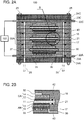
- Figs. 1A and 2A are diagrams illustrating an example of an electrochemical hydrogen pump according to Embodiment 1.
- Fig. 1B is an enlarged view of portion B of the electrochemical hydrogen pump illustrated in Fig. 1A .
- Fig. 2B is an enlarged view of portion B of the electrochemical hydrogen pump illustrated in Fig. 2A .
- Fig. 1A illustrates a vertical section of an electrochemical hydrogen pump 100 that includes a straight line passing through the center of the electrochemical hydrogen pump 100 and the center of a cathode gas outlet manifold 50 in plan view.
- Fig. 2A illustrates a vertical section of the electrochemical hydrogen pump 100 that includes a straight line passing through the center of the electrochemical hydrogen pump 100, the center of an anode gas inlet manifold 27, and the center of an anode gas outlet manifold 30 in plan view.
- the electrochemical hydrogen pump 100 includes at least one hydrogen pump unit 100A.
- the electrochemical hydrogen pump 100 has a stack of multiple hydrogen pump units 100A.
- Figs. 1A and 2A there is a three-tier stack of hydrogen pump units 100A. This, however, is not the only possible number of hydrogen pump units 100A. That is, any number of hydrogen pump units 100A can be used as appropriate on the basis of the operating conditions, such as the volume of hydrogen the electrochemical hydrogen pump 100 pressurizes.
- a hydrogen pump unit 100A includes an electrolyte membrane 11, an anode AN, a cathode CA, a cathode separator 16, an anode separator 17, and an insulator 21.
- an electrolyte membrane 11, an anode catalyst layer 13, a cathode catalyst layer 12, an anode gas diffusion layer 15, a cathode gas diffusion layer 14, an anode separator 17, and a cathode separator 16 are stacked together.
- the anode AN is on a first primary surface of the electrolyte membrane 11.
- the anode AN is an electrode that includes an anode catalyst layer 13 and an anode gas diffusion layer 15.
- the cathode CA is on a second primary surface of the electrolyte membrane 11.
- the cathode CA is an electrode that includes a cathode catalyst layer 12 and a cathode gas diffusion layer 14.
- MEA membrane electrode assembly
- the electrolyte membrane 11 is proton-conductive.
- the electrolyte membrane 11 can be of any type as long as it is proton-conductive.
- the electrolyte membrane 11 can be a fluoropolymer or hydrocarbon polymer electrolyte membrane, although these are not the only possibilities.
- Specific examples of membranes that can be used as the electrolyte membrane 11 include Nafion ® (DuPont) and Aciplex ® (Asahi Kasei Corporation) membranes.
- the anode catalyst layer 13 is on the first primary surface of the electrolyte membrane 11.
- An example of a catalyst metal contained in the anode catalyst layer 13 is platinum, but this is not the only possibility.
- the cathode catalyst layer 12 is on the second primary surface of the electrolyte membrane 11.
- An example of a catalyst metal contained in the cathode catalyst layer 12 is platinum, but this is not the only possibility.
- catalyst carriers for the cathode and anode catalyst layers 12 and 13 include, but are not limited to, carbon particles, for example of carbon black or graphite, and electrically conductive oxide particles.
- the cathode gas diffusion layer 14 is on the cathode catalyst layer 12.
- the cathode gas diffusion layer 14 is a porous medium, conducts electricity, and allows gases to diffuse therethrough. Desirably, the cathode gas diffusion layer 14 is elastic so that it will properly follow the displacement and deformation of structural elements of the electrochemical hydrogen pump 100 that occur in response to a differential pressure between the cathode CA and anode AN while the hydrogen pump 100 is in operation.
- the cathode gas diffusion layer 14 in the electrochemical hydrogen pump 100 is an element made from carbon fibers.
- the cathode gas diffusion layer 14 may be a porous carbon fiber sheet, such as a piece of carbon paper, carbon cloth, or carbon felt.
- the base material for the cathode gas diffusion layer 14 does not need to be a carbon fiber sheet.
- the base material for the cathode gas diffusion layer 14 may be a sintered mass of metal fibers, for example made from titanium, a titanium alloy, or stainless steel, a sintered mass of metal particles made from any such metal, etc.
- the anode gas diffusion layer 15 is on the anode catalyst layer 13.
- the anode gas diffusion layer 15 is a porous medium, conducts electricity, and allows gases to diffuse therethrough.
- the anode gas diffusion layer 15 is highly rigid so that it will limit the displacement and deformation of structural elements of the electrochemical hydrogen pump 100 that occur in response to a differential pressure between the cathode CA and anode AN while the hydrogen pump 100 is in operation.
- the anode gas diffusion layer 15 in the electrochemical hydrogen pump 100 includes a porous carbon sheet that is a powder molded body.
- This powder molded body may be, for example, a sheet-shaped sintered body made from carbon particles (carbon powder sintered body).
- the anode gas diffusion layer 15 may include, as illustrated in Fig. 3 , a porous carbon sheet 15S whose first surface layer 15B, which is closer to the anode separator 17, contains amorphous carbon.
- the porous carbon sheet 15S can be a sheet-shaped sintered body made from carbon particles.
- the carbon particles in the porous carbon sheet 15S are of amorphous carbon, in which carbon-carbon bonds are in an amorphous structure.
- amorphous carbon is highly rigid. That is, the higher the percentage of amorphous carbon in the porous carbon sheet 15S is, the more rigid the porous carbon sheet 15S is.
- the porous carbon sheet 15S therefore, has higher rigidity in its first surface layer 15B, which is closer to the anode separator 17, than in the layer 15A lying under this first surface layer 15B, or an inner layer 15A.
- the porous carbon sheet 15S is a stack in which one primary surface of its first surface layer 15B is in contact with a primary surface of the anode separator 17, with the other primary surface of the first surface layer 15B in contact with one primary surface of the layer 15A therebeneath (inner layer).
- the other primary surface of the inner layer 15A is in contact with the anode catalyst layer 13.
- amorphous carbon materials include glassy carbon (glass-like carbon) and diamond-like carbon (DLC).
- the anode separator 17 is an element disposed on the anode AN.
- the cathode separator 16 is an element disposed on the cathode CA.
- a recess In the middle of each of the cathode and anode separators 16 and 17 is a recess. In these recesses, the cathode and anode gas diffusion layers 14 and 15 are contained respectively.
- an MEA as described above is sandwiched between cathode and anode separators 16 and 17, forming a hydrogen pump unit 100A.
- the primary surface of the cathode separator 16 touching the cathode gas diffusion layer 14 has a cathode gas flow channel 32 created therein, for example a serpentine one that includes multiple U-shaped turns and multiple straight stretches in plan view.
- the straight stretches of the cathode gas flow channel 32 extend perpendicular to the plane of the page of Fig. 1A .
- Such a cathode gas flow channel 32 is by way of example and is not the only possibility.
- the cathode gas flow channel may be formed by multiple linear passages.
- the primary surface of the anode separator 17 touching the anode gas diffusion layer 15 has an anode gas flow channel 33 created therein, for example a serpentine one that includes multiple U-shaped turns and multiple straight stretches in plan view.
- the straight stretches of the anode gas flow channel 33 extend perpendicular to the plane of the page of Fig. 2A .
- Such an anode gas flow channel 33 is by way of example and is not the only possibility.
- the anode gas flow channel may be formed by multiple linear passages.
- the electrochemical hydrogen pump 100 also includes first and second end plates, which are at the ends in the direction of stacking of the hydrogen pump units 100A, and fasteners 25, which fasten the hydrogen pump units 100A, first end plate, and second end plate together in the direction of stacking.
- a cathode end plate 24C and an anode end plate 24A correspond to these first and second end plates, respectively. That is, the anode end plate 24A is an end plate disposed on the anode separator 17 located at a first end in the direction of stacking of the components of the hydrogen pump units 100A.
- the cathode end plate 24C is an end plate disposed on the cathode separator 16 located at a second end in the direction of stacking of the components of the hydrogen pump units 100A.
- the fasteners 25 can be of any type as long as they can fasten the hydrogen pump units 100A, cathode end plate 24C, and anode end plate 24A together in the direction of stacking.
- the fasteners 25 can be bolts and nuts with a disk spring or a similar tool.
- the bolts as a component of the fasteners 25 in that case may be made to penetrate only through the anode and cathode end plates 24A and 24C.
- the bolts for the electrochemical hydrogen pump 100 penetrate through the components of the three-tier stack of hydrogen pump units 100A, a cathode feed plate 22C, a cathode insulating plate 23C, an anode feed plate 22A, an anode insulating plate 23A, the anode end plate 24A, and the cathode end plate 24C.
- the fasteners 25 apply a desired pressure to the hydrogen pump units 100A by compressing an end face of the cathode separator 16 at the second end in the aforementioned direction of stacking and an end face of the anode separator 17 at the first end in the aforementioned direction of stacking with the cathode and anode end plates 24C and 24A, respectively, with the cathode feed plate and insulating plate 22C and 23C and the anode feed plate and insulating plate 22A and 23A interposed therebetween.
- the electrochemical hydrogen pump 100 keeps its three-tier stack of hydrogen pump units 100A properly stacked in the aforementioned direction of stacking by making use of fastening pressure applied by fasteners 25. Since the bolts as a component of the fasteners 25 penetrate through the components of the electrochemical hydrogen pump 100, furthermore, these components are well prevented from moving in plane.
- the cathode gas flow channel 32 through which cathode gas coming out of the cathode gas diffusion layer 14 flows, of each individual hydrogen pump unit 100A in the electrochemical hydrogen pump 100 communicates with one another.
- the cathode gas outlet manifold 50 is a series of through holes created through the components of the three-tier stack of hydrogen pump units 100A and the cathode end plate 24C and a blind hole created in the anode end plate 24A.
- the cathode end plate 24C also has a cathode gas outlet line 26.
- the cathode gas outlet line 26 may be piping through which hydrogen (H 2 ) discharged from the cathode CA flows.
- the cathode gas outlet line 26 communicates with this cathode gas outlet manifold 50.
- the cathode gas outlet manifold 50 furthermore, communicates with one end of the cathode gas flow channel 32 of each individual hydrogen pump unit 100A via separate cathode gas conduits 34.
- streams of hydrogen that have passed through the cathode gas flow channel 32 and cathode gas conduit 34 of each individual hydrogen pump unit 100A are combined together at the cathode gas outlet manifold 50.
- the combined stream of hydrogen is then guided to the cathode gas outlet line 26.
- each individual hydrogen pump unit 100A communicates with one another via the cathode gas conduit 34 of each hydrogen pump unit 100A and the cathode gas outlet manifold 50.
- ring-shaped seals 40 such as O-rings, surrounding the cathode gas outlet manifold 50 in plan view.
- the cathode gas outlet manifold 50 is sealed with these seals 40 properly.
- the anode end plate 24A has an anode gas inlet line 29.
- the anode gas inlet line 29 may be piping through which anode gas to be supplied to the anode AN flows.
- An example of such an anode gas is a hydrogen-containing gas with steam therein.
- the anode gas inlet line 29 communicates with a tubular anode gas inlet manifold 27.
- the anode gas inlet manifold 27 is a series of through holes created through the components of the three-tier stack of hydrogen pump units 100A and the anode end plate 24A.
- the anode gas inlet manifold 27 communicates with a first end of the anode gas flow channel 33 of each individual hydrogen pump unit 100A via separate first anode gas conduits 35.
- anode gas supplied from the anode gas inlet line 29 to the anode gas inlet manifold 27 is distributed to each individual hydrogen pump unit 100A through the first anode gas conduit 35 of each hydrogen pump unit 100A. While passing through the anode gas flow channel 33, the distributed anode gas is supplied to the anode catalyst layer 13 through the anode gas diffusion layer 15.
- the anode end plate 24A also has an anode gas outlet line 31.
- the anode gas outlet line 31 may be piping through which anode gas discharged from the anode AN flows.
- the anode gas outlet line 31 communicates with a tubular anode gas outlet manifold 30.
- the anode gas outlet manifold 30 is a series of through holes created through the components of the three-tier stack of hydrogen pump units 100A and the anode end plate 24A.
- the anode gas outlet manifold 30 communicates with a second end of the anode gas flow channel 33 of each individual hydrogen pump unit 100A via separate second anode gas conduits 36.
- streams of anode gas that have passed through the anode gas flow channel 33 of each individual hydrogen pump units 100A are supplied to the anode gas outlet manifold 30, and combined together there, through each individual second anode gas conduit 36.
- the combined stream of anode gas is then guided to the anode gas outlet line 31.
- ring-shaped seals 40 such as O-rings, surrounding the anode gas inlet and outlet manifolds 27 and 30 in plan view.
- the anode gas inlet and outlet manifolds 27 and 30 are sealed with these seals 40 properly.
- the electrochemical hydrogen pump 100 includes a voltage applicator 102.
- the voltage applicator 102 is a device that applies a voltage across the anode and cathode catalyst layers 13 and 12. Specifically, the high potential of the voltage applicator 102 has been applied to the anode catalyst layer 13, and the low potential of the voltage applicator 102 has been applied to the cathode catalyst layer 12.
- the voltage applicator 102 can be of any type as long as it can apply a voltage across the anode and cathode catalyst layers 13 and 12.
- the voltage applicator 102 may be a device that controls the voltage applied across the anode and cathode catalyst layers 13 and 12.
- the voltage applicator 102 in that case includes a DC-to-DC converter if it is connected to a direct-current power supply, such as a battery, solar cell, or fuel cell, or includes an AC-to-DC converter if it is connected to an alternating-current power supply, such as mains electricity.
- a direct-current power supply such as a battery, solar cell, or fuel cell
- AC-to-DC converter if it is connected to an alternating-current power supply, such as mains electricity.
- the voltage applicator 102 may be, for example, a multi-range power supply, which controls the voltage it applies across the anode and cathode catalyst layers 13 and 12 and controls the current to flow between the anode and cathode catalyst layers 13 and 12 so that the amount of electricity supplied to the hydrogen pump units 100A will match a particular preset value.
- the low-potential terminal of the voltage applicator 102 is connected to the cathode feed plate 22C, and the high-potential terminal of the voltage applicator 102 is connected to the anode feed plate 22A.
- the cathode feed plate 22C is in electrical contact with the cathode separator 16 located at the second end in the aforementioned direction of stacking
- the anode feed plate 22A is in electrical contact with the anode separator 17 located at the first end in the aforementioned direction of stacking.
- a hydrogen supply system that includes this electrochemical hydrogen pump 100 can also be built.
- the hydrogen supply system is equipped as necessary for its operation of supplying hydrogen.
- the hydrogen supply system may be fitted with a dew-point controller (e.g., a humidifier) that controls the dew point of the mixed gas produced by the mixing together of a heavily humidified hydrogen-containing anode gas discharged from the anode AN through the anode gas outlet line 31 and an only slightly humidified hydrogen-containing anode gas supplied from an external hydrogen source through the anode gas inlet line 29.
- a dew-point controller e.g., a humidifier
- the hydrogen-containing anode gas from an external hydrogen source in that case may be produced using, for example, a water electrolyzer.
- the hydrogen supply system may be fitted with, for example, a temperature sensor that detects the temperature of the electrochemical hydrogen pump 100, a hydrogen reservoir that provides a temporary storage for hydrogen discharged from the cathodes CA in the electrochemical hydrogen pump 100, and a pressure sensor that detects the pressure of hydrogen gas inside the hydrogen reservoir.
- a temperature sensor that detects the temperature of the electrochemical hydrogen pump 100
- a hydrogen reservoir that provides a temporary storage for hydrogen discharged from the cathodes CA in the electrochemical hydrogen pump 100
- a pressure sensor that detects the pressure of hydrogen gas inside the hydrogen reservoir.
- the electrochemical hydrogen pump 100 may have a dead-end structure, in which the pump 100 has no anode gas outlet manifold 30 and no anode gas outlet line 31 and pressurizes at its cathodes CA all hydrogen in the anode gas supplied to its anodes AN through the anode gas inlet manifold 27.
- the following operation may be carried out as a result of, for example, the processor of a controller, not illustrated, reading a control program stored in a memory in the controller.
- the involvement of a controller in this operation is optional.
- the person who operates the pump 100 may undertake part of the operation. In the following, a case is described in which the anode gas to be supplied to the anodes AN in the electrochemical hydrogen pump 100 is a hydrogen-containing gas with steam therein.
- a low-pressure hydrogen-containing gas is supplied to the anodes AN in the electrochemical hydrogen pump 100.
- a voltage from the voltage applicator 102 is fed to the electrochemical hydrogen pump 100.
- hydrogen molecules dissociate into hydrogen ions (protons) and electrons through oxidation (formula (1)).
- the protons move to the cathode catalyst layer 12 by traveling through the inside of the electrolyte membrane 11.
- the electrons move to the cathode catalyst layer 12 through the voltage applicator 102.
- the hydrogen (H 2 ) produced at the cathode CA can be pressurized by increasing the pressure drop in a hydrogen outlet line using a flow controller, not illustrated.
- a hydrogen outlet line is the cathode gas outlet line 26 illustrated in Fig. 2A .
- An example of a flow controller is a back pressure valve, regulator valve, or similar device provided in the hydrogen outlet line.
- a hydrogen-containing gas is supplied to the anodes AN in the electrochemical hydrogen pump 100, and the hydrogen pump 100 pressurizes the hydrogen in the hydrogen-containing gas at its cathodes CA in response to a voltage applied by the voltage applicator 102.
- the electrochemical hydrogen pump 100 pressurizes hydrogen in this way, and the hydrogen pressurized at the cathodes CA is, for example, stored in a hydrogen reservoir, not illustrated, temporarily.
- the hydrogen stored in the hydrogen reservoir is supplied when needed to an entity that requires hydrogen.
- An example of an entity that requires hydrogen is a fuel cell that uses hydrogen to generate electricity.
- Fig. 4 is a diagram illustrating exemplary results of an analysis by Raman spectroscopy of a porous carbon sheet in an electrochemical hydrogen pump according to Embodiment 1.
- the horizontal axis represents the wavenumber (reciprocal of wavelength) (cm -1 ) as a unit proportional to energy, and the vertical axis represents the intensity of scattered light.
- the Raman spectrum in Fig. 4 was separated into Gaussian components, with the result that the spectrum included a spectrum with a Raman peak around approximately 1600 cm -1 (G band), a spectrum with a Raman peak around approximately 1350 cm -1 (D1 band), a spectrum with a Raman peak around approximately 1500 cm -1 (D2 band), and a spectrum with a Raman peak around approximately 1200 cm -1 (D3 band) as shown in the same drawing.
- the G band appears to be a spectrum derived from crystalline carbon.
- the integrated intensity of each band was therefore measured.
- the integrated intensity was 1671 for the G band, 2870 for the D1 band, 853 for the D2 band, and 708 for the D3 band.
- the ratio between the integrated intensity of the D bands and that of the G band (D/G) given by this is 2.651.
- the measurements also indicate that the ratio between the integrated intensity of the D1 band, which corresponds to the characteristic Raman peak among the D bands (around approximately 1350 cm -1 ), and that of the G band (D1/G) is 1.717.
- the porous carbon sheet 15S in the electrochemical hydrogen pump 100 is of low crystallinity enough that the ratio between the integrated intensity of the D bands and that of the G band (D/G) exceeds "1" (D/G > 1) when the sheet 15S is analyzed by Raman spectroscopy.
- the electrochemical hydrogen pump 100 can cost less in terms of its anode gas diffusion layer 15 than with an anode gas diffusion layer made of metal. At the same time, the risk of the buckling of the anode gas diffusion layer 15 into the anode separator 17 can be reduced.
- the electrochemical hydrogen pump 100 offers enhanced rigidity, for example compared with ones having a porous carbon sheet made from carbon fibers, by virtue of having a porous carbon sheet 15S made from a powder molded body.
- a porous carbon sheet 15S containing amorphous carbon has relatively few of sharp points observed with metal porous media that have hitherto been used. Even when such a porous carbon sheet 15S is pressed against an electrolyte membrane 11, it is unlikely that the electrolyte membrane 11 is damaged.
- the electrochemical hydrogen pump 100 according to this embodiment therefore, offers reduced risk of damage to the electrolyte membrane 11 compared with known ones made with a metal porous medium.
- amorphous carbon in which carbon-carbon bonds are in an amorphous structure, is more rigid than carbon in which carbon-carbon bonds are in a crystalline structure.
- the anode gas diffusion layer 15 in the electrochemical hydrogen pump 100 according to this embodiment is therefore acceptably rigid because the porous carbon sheet 15S in it contains amorphous carbon in such an amount that D/G > 1.0 when the sheet 15S is analyzed by Raman spectroscopy.
- the porous carbon sheet 15S in the electrochemical hydrogen pump 100 has higher rigidity in its first surface layer 15B, which is closer to the anode separator 17, than in the layer 15A lying under this first surface layer 15B.
- the electrochemical hydrogen pump 100 suffers to a lesser degree the deformation of its anode gas diffusion layer 15 caused by a differential pressure (high pressure) that occurs between the cathode CA and anode AN during hydrogen pressurization.
- the electrochemical hydrogen pump 100 according to this embodiment offers reduced risk of the buckling of the anode gas diffusion layer 15 in the anode gas flow channel 33, which is in the anode separator 17, caused by such a differential pressure.
- An electrochemical hydrogen pump 100 according to Example 1 is the same as the electrochemical hydrogen pump 100 according to Embodiment 1 except for the structure of the porous carbon sheet 15S, which is described below.
- the porous carbon sheet 15S in the electrochemical hydrogen pump 100 has a lower porosity in its first surface layer 15B, which is closer to the anode separator 17, than in the layer 15A lying under this first surface layer 15B.
- This porosity can be determined using, for example, a mercury porosimeter (trade name, AutoPore III 9410; Shimadzu Corporation). With this device, the volume of pores having a diameter of several nm to approximately 500 ⁇ m can be measured on the basis of pressure intrusion of mercury into the pores. The pore volume and solid portion in each of the first surface layer 15B and the layer 15A therebeneath give the porosity percentages in these layers.
- the porous carbon sheet 15S is, for example, a sintered body made from carbon particles, reducing the porosity of the porous carbon sheet 15S will increase necking between the carbon particles forming the porous carbon sheet 15S (bonding together of the particles). Hence the rigidity of the porous carbon sheet 15S is improved.
- the electrochemical hydrogen pump 100 according to this example therefore offers improved rigidity of the first surface layer 15B, which is closer to the anode separator 17, of its porous carbon sheet 15S.
- the electrochemical hydrogen pump 100 suffers to a lesser degree the deformation of its anode gas diffusion layer 15 caused by a differential pressure that occurs between the cathode CA and anode AN during hydrogen pressurization.
- the electrochemical hydrogen pump 100 according to this example offers reduced risk of the buckling of the anode gas diffusion layer 15 in the anode gas flow channel 33, which is in the anode separator 17, caused by such a differential pressure.
- the electrochemical hydrogen pump 100 according to this example may be the same as the electrochemical hydrogen pump 100 according to Embodiment 1.
- An electrochemical hydrogen pump 100 according to Example 2 is the same as the electrochemical hydrogen pump 100 according to Embodiment 1 except for the structure of the porous carbon sheet 15S, which is described below.
- the layer 15A lying under the first surface layer 15B of the porous carbon sheet 15S in the electrochemical hydrogen pump 100 may be an intermediate layer located in the middle of the porous carbon sheet 15S in the direction of thickness as illustrated in Fig. 5 .
- This intermediate layer therefore has lower rigidity than the first surface layer 15B, which is closer to the anode separator 17.
- the intermediate layer in this case may be made of, for example, carbon in which carbon-carbon bonds are in a crystalline structure. If the porous carbon sheet 15S is, for example, a sintered body made from carbon particles, the intermediate layer may have a higher porosity than the first surface layer 15B.
- the porous carbon sheet 15S in the electrochemical hydrogen pump 100 has higher rigidity in its second surface layer 15C, which is closer to the anode catalyst layer 13, than in the layer 15A lying under the second surface layer 15C (intermediate layer) as illustrated in Fig. 5 .
- the porous carbon sheet 15S may have a lower porosity in its second surface layer 15C, which is closer to the anode catalyst layer 13, than in the layer 15A lying under the second surface layer 15C (intermediate layer).
- This porosity can be determined using, for example, a mercury porosimeter (trade name, AutoPore III 9410; Shimadzu Corporation).
- the porous carbon sheet 15S is, for example, a sintered body made from carbon particles, reducing the porosity of the porous carbon sheet 15S will increase necking between the carbon particles forming the porous carbon sheet 15S (bonding together of the particles). Hence the rigidity of the porous carbon sheet 15S is improved.
- the electrochemical hydrogen pump 100 according to this example therefore offers improved rigidity of the first surface layer 15B, which is closer to the anode separator 17, and the second surface layer 15C, which is closer to the anode catalyst layer 13.
- the electrochemical hydrogen pump 100 suffers to a lesser degree the deformation of its anode gas diffusion layer 15 caused by a differential pressure that occurs between the cathode CA and anode AN during hydrogen pressurization.
- the electrochemical hydrogen pump 100 according to this example offers reduced risk of the buckling of the anode gas diffusion layer 15 in the anode gas flow channel 33, which is in the anode separator 17, caused by such a differential pressure.
- the electrochemical hydrogen pump 100 according to this example may be the same as the electrochemical hydrogen pump 100 according to Embodiment 1 or Example 1 of Embodiment 1.
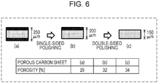
- Fig. 6 is a diagram illustrating exemplary measured porosity percentages of the porous carbon sheet in the electrochemical hydrogen pump according to Example 3 of Embodiment 1.
- Fig. 6 (a) the porosity of an approximately 250- ⁇ m thick porous carbon sheet was measured, for example using a mercury porosimeter (trade name, AutoPore III 9410; Shimadzu Corporation). This porosity was approximately 29%.
- Fig. 6 (a) one primary surface of the porous carbon sheet in Fig. 6 (a) was polished in the direction of thickness to remove approximately 50 ⁇ m as illustrated in Fig. 6 (b) (single-sided polishing).
- Fig. 6 (b) the porosity of the approximately 200- ⁇ m thick porous carbon sheet was measured, for example using a mercury porosimeter (trade name, AutoPore III 9410; Shimadzu Corporation). This porosity was approximately 32%.
- Fig. 6 (c) the porosity of the approximately 150- ⁇ m thick porous carbon sheet was measured, for example using a mercury porosimeter (trade name, AutoPore III 9410; Shimadzu Corporation). This porosity was approximately 34%.
- the porous carbon sheet in Fig. 6 (a) may be a porous carbon sheet 15S that includes a first surface layer 15B, an inner layer 15A (intermediate layer), and a second surface layer 15C as presented in Example 2 ( Fig. 5 ).
- the high-porosity intermediate layer corresponds to a region with a low density of carbon particles.
- the low-porosity surface layers correspond to regions with a high density of carbon particles.
- a porous carbon sheet that has different percentages of porosity in its intermediate and surface layers may be a pressurized powder body that has been sintered at a desired temperature and pressure, but this is not the only possibility.
- a porous carbon sheet can also be formed by making the diameter of carbon particles in the surface layers smaller than that in the intermediate layer.
- the electrochemical hydrogen pump 100 according to this example may be the same as the electrochemical hydrogen pump 100 according to any of Embodiment 1 or Example 1 or 2 of Embodiment 1.
- An electrochemical hydrogen pump 100 according to Example 4 is the same as the electrochemical hydrogen pump 100 according to Embodiment 1 except for the structure of the porous carbon sheet 15S, which is described below.
- the porosity, flexural strength, and Young's modulus in the direction of thickness of the porous carbon sheet 15S was measured with a compressive strength of 16 MPa or 60 MPa of the porous carbon sheet 15S in the direction of thickness. The results were as follows.
- the porosity was measured using a mercury porosimeter (trade name, AutoPore III 9410; Shimadzu Corporation).
- the flexural strength and Young's modulus were measured by the three-point bend test set forth in JIS R1601 standard “Testing method for flexural strength (modulus of rupture) of fine ceramics” and that in JIS R1602 standard “Testing methods for elastic modulus of fine ceramics,” respectively.
- the measurement of Young's modulus was based on calculation in the flat region of the stress-strain curve obtained in the bend test.
- the compressive strength of the porous carbon sheet 15S in the direction of thickness and the flexural strength and Young's modulus of the porous carbon sheet 15S appear to be in a strongly linear positive correlation.
- the compressive strength of the porous carbon sheet 15S in the direction of thickness and the porosity of the porous carbon sheet 15S seem to be in a strongly linear negative correlation.
- the maximum porosity, minimum flexural strength, and minimum Young's modulus in the direction of thickness at which the porous carbon sheet 15S is unbreakable when the porous carbon sheet 15S has a desired compressive strength (e.g., 20 MPa) in the direction of thickness can be calculated by linear approximation of the measured data above. The calculations give 45%, 10 MPa, and 2.5 GPa, respectively.
- the porous carbon sheet 15S in the electrochemical hydrogen pump 100 may have a Young's modulus in the direction of thickness higher than or equal to 2.5 GPa at least in its first surface layer 15B, which is closer to the anode separator 17.
- the porous carbon sheet 15S moreover, may have a flexural strength higher than or equal to 10 MPa at least in its first surface layer 15B, which is closer to the anode separator 17. If these are the case, the porous carbon sheet 15S has a porosity lower than or equal to 45% at least in its first surface layer 15B, which is closer to the anode separator 17.
- the porous carbon sheet 15S in that case may also have a porosity lower than or equal to 45% at least in its second surface layer 15C, which is closer to the anode catalyst layer 13.
- the electrochemical hydrogen pump 100 When its porous carbon sheet 15S has a desired compressive strength (e.g., 20 MPa) in the direction of thickness, therefore, the electrochemical hydrogen pump 100 according to this example suffers to a lesser degree the deformation of its anode gas diffusion layer 15 caused by a differential pressure (high pressure) that occurs between the cathode CA and anode AN during hydrogen pressurization than it would if the Young's modulus in the direction of thickness of the first surface layer 15B, which is closer to the anode separator 17, were lower than 2.5 GPa.
- a differential pressure high pressure
- the electrochemical hydrogen pump 100 moreover, suffers to a lesser degree the deformation of its anode gas diffusion layer 15 caused by a differential pressure (high pressure) that occurs between the cathode CA and anode AN during hydrogen pressurization than it would if the flexural strength of the first surface layer 15B, which is closer to the anode separator 17, were lower than 10 MPa.
- the electrochemical hydrogen pump 100 according to this example offers reduced risk of the buckling of the anode gas diffusion layer 15 in the flow channel 33 in the anode separator 17 caused by such a differential pressure.
- An electrochemical hydrogen pump 100 whose porous carbon sheet 15S can withstand a compressive strength of approximately 20 MPa in the direction of thickness finds a broader range of uses than otherwise.
- the electrochemical hydrogen pump 100 can be used when small hydrogen cylinders for transport, for example by truck, are loaded with hydrogen at approximately 15 MPa.
- the electrochemical hydrogen pump 100 can also be used when packs of bundled hydrogen cylinders for transport, for example by truck with or without a crane, are loaded with hydrogen at approximately 15 MPa or approximately 20 MPa.
- the maximum porosity, minimum flexural strength, and minimum Young's modulus in the direction of thickness at which the porous carbon sheet 15S is unbreakable when the porous carbon sheet 15S has a desired compressive strength (e.g., 40 MPa) in the direction of thickness can also be calculated by linear approximation of the measured data above. The calculations give 39%, 20 MPa, and 7.8 GPa, respectively.
- the porous carbon sheet 15S in the electrochemical hydrogen pump 100 may have a Young's modulus in the direction of thickness higher than or equal to 7.8 GPa at least in its first surface layer 15B, which is closer to the anode separator 17.
- the porous carbon sheet 15S moreover, may have a flexural strength higher than or equal to 20 MPa at least in its first surface layer 15B, which is closer to the anode separator 17. If these are the case, the porous carbon sheet 15S has a porosity lower than or equal to 39% at least in its first surface layer 15B, which is closer to the anode separator 17.
- the porous carbon sheet 15S in that case may also have a porosity lower than or equal to 39% at least in its second surface layer 15C, which is closer to the anode catalyst layer 13.
- the electrochemical hydrogen pump 100 When its porous carbon sheet 15S has a desired compressive strength (e.g., 40 MPa) in the direction of thickness, therefore, the electrochemical hydrogen pump 100 according to this example suffers to a lesser degree the deformation of its anode gas diffusion layer 15 caused by a differential pressure (high pressure) that occurs between the cathode CA and anode AN during hydrogen pressurization than it would if the Young's modulus in the direction of thickness of the first surface layer 15B, which is closer to the anode separator 17, were lower than 7.8 GPa.
- a differential pressure high pressure
- the electrochemical hydrogen pump 100 moreover, suffers to a lesser degree the deformation of its anode gas diffusion layer 15 caused by a differential pressure (high pressure) that occurs between the cathode CA and anode AN during hydrogen pressurization than it would if the flexural strength of the first surface layer 15B, which is closer to the anode separator 17, were lower than 20 MPa.
- the electrochemical hydrogen pump 100 according to this example offers reduced risk of the buckling of the anode gas diffusion layer 15 in the anode gas flow channel 33, which is in the anode separator 17, caused by such a differential pressure.
- An electrochemical hydrogen pump 100 whose porous carbon sheet 15S can withstand a compressive strength of approximately 40 MPa in the direction of thickness finds a broader range of uses than otherwise.
- the electrochemical hydrogen pump 100 can be used as a hydrogen compressor at hydrogen stations for forklifts or fuel cell vehicles.
- the electrochemical hydrogen pump 100 can be used when high-pressure hydrogen at approximately 40 MPa is supplied to hydrogen accumulators from hydrogen cylinders filled with hydrogen at approximately 15 MPa.
- the electrochemical hydrogen pump 100 according to this example may be the same as the electrochemical hydrogen pump 100 according to any of Embodiment 1 or Examples 1 to 3 of Embodiment 1.
- An electrochemical hydrogen pump 100 according to Example 5 is the same as the electrochemical hydrogen pump 100 according to Embodiment 1 except for the structure of the porous carbon sheet 15S, which is described below.
- the porous carbon sheet 15S in the electrochemical hydrogen pump 100 has a peak pore diameter smaller than the thickness of the electrolyte membrane 11.
- the thickness of the electrolyte membrane 11 is between approximately 20 ⁇ m and approximately 50 ⁇ m for example, but does not need to be this.
- This peak pore diameter can be determined using, for example, a mercury porosimeter (trade name, AutoPore III 9410; Shimadzu Corporation). With this device, the distribution of diameters of pores having a diameter of several nm to approximately 500 ⁇ m can be measured on the basis of pressure intrusion of mercury into the pores. This distribution of diameters of pores gives the peak pore diameter.
- the electrolyte membrane 11 could break while the electrochemical hydrogen pump 100 is operating to pressurize hydrogen as a result of the electrolyte membrane 11 falling into a pore in the porous carbon sheet 15S because of a differential pressure that occurs between the cathode CA and anode AN.
- the electrochemical hydrogen pump 100 according to this example offers reduced risk of such an event by virtue of the peak pore diameter of the porous carbon sheet 15S being smaller than the thickness of the electrolyte membrane 11.
- the electrochemical hydrogen pump 100 according to this example may be the same as the electrochemical hydrogen pump 100 according to any of Embodiment 1 or Examples 1 to 4 of Embodiment 1.
- An electrochemical hydrogen pump 100 according to Example 6 is the same as the electrochemical hydrogen pump 100 according to Embodiment 1 except for the structure of the porous carbon sheet 15S, which is described below.
- the porous carbon sheet 15S in the electrochemical hydrogen pump 100 has an overall porosity higher than or equal to 20%.
- This porosity can be determined using, for example, a mercury porosimeter (trade name, AutoPore III 9410; Shimadzu Corporation). With this device, the volume of pores having a diameter of several nm to approximately 500 ⁇ m can be measured on the basis of pressure intrusion of mercury into the pores. The overall pore volume and solid portion of the porous carbon sheet 15S give this porosity.
- the electrochemical hydrogen pump 100 offers sufficient diffusibility of the anode gas diffusion layer 15 in terms of gas diffusion into the anode catalyst layer 13 because the 20% or higher overall porosity of the porous carbon sheet 15S encourages the presence of pores leading to the outside (open holes) in the anode gas diffusion layer 15. By virtue of this, anode gas coming from the anode separator 17 is supplied properly to the anode catalyst layer 13 through the anode gas diffusion layer 15.
- the electrochemical hydrogen pump 100 according to this example may be the same as the electrochemical hydrogen pump 100 according to any of Embodiment 1 or Examples 1 to 5 of Embodiment 1.
- An electrochemical hydrogen pump 100 according to Embodiment 2 is the same as the electrochemical hydrogen pump 100 according to Embodiment 1 except that the second surface layer 15C, which is closer to the anode catalyst layer 13, of its anode gas diffusion layer 15 is water-repellent.
- the amount of water pushed back to the anode AN increases with elevating hydrogen gas pressure at the cathode CA. As the hydrogen gas pressure at the cathode CA increases, therefore, it becomes more likely that the anode AN floods with water pushed back to the anode AN. When such an event of flooding occurs and interferes with gas diffusion at the anode AN, the electrochemical hydrogen pump 100 may become less efficient in hydrogen pressurization because of increased diffusion resistance in the electrochemical hydrogen pump 100.
- the anode gas diffusion layer 15 in the electrochemical hydrogen pump 100 has a water-repellent second surface layer 15C, which is closer to the anode catalyst layer 13.
- the anode gas diffusion layer 15 is a sintered body made from carbon particles
- a material containing a water-repellent resin such as a fluoropolymer
- the sintered body may be impregnated with such a material containing a water-repellent resin to make the carbon particles in the second surface layer 15C, which is closer to the anode catalyst layer 13, of the anode gas diffusion layer 15 water-repellent.
- An example of a material containing a water-repellent resin is a solution of dispersed fine powder of PTFE in a solvent.
- An example of how to apply the material containing a water-repellent resin is spray coating.
- the electrochemical hydrogen pump 100 according to this embodiment may be the same as the electrochemical hydrogen pump 100 according to any of Embodiment 1 or Examples 1 to 6 of Embodiment 1.
- An electrochemical hydrogen pump 100 according to Embodiment 3 is the same as the electrochemical hydrogen pump 100 according to Embodiment 1 except that the first surface layer 15B, which is closer to the anode separator 17, of its anode gas diffusion layer 15 is hydrophilic.
- an electrolyte membrane 11 becomes highly proton-conductive under high-temperature and highly humidified conditions (e.g., approximately 60°C), and an electrochemical hydrogen pump 100 becomes more efficient in hydrogen pressurization under such conditions.
- an electric current flows between an anode AN and a cathode CA in an electrochemical hydrogen pump 100
- protons move inside an electrolyte membrane 11 from the anode AN to the cathode CA, bringing water with them.
- part of the electroosmotic water which has moved from the anode AN to the cathode CA, is drained from the cathode CA together with high-pressure hydrogen gas.
- the electrochemical hydrogen pump 100 may become less efficient in hydrogen pressurization because the electrolyte membrane 11 in the electrochemical hydrogen pump 100 dries more quickly.
- the anode gas diffusion layer 15 in the electrochemical hydrogen pump 100 has a hydrophilic first surface layer 15B, which is closer to the anode separator 17.
- this first surface layer 15B has a water-retaining function. Water in anode gas can therefore be easily supplied to the electrolyte membrane 11 through the anode gas diffusion layer 15, hence reduced risk of drying up of the electrolyte membrane 11 in the electrochemical hydrogen pump 100.
- the anode gas diffusion layer 15 is a sintered body made from carbon particles
- these carbon particles can be made hydrophilic by introducing an oxygen-containing functional group, such as the carboxyl, hydroxyl, or carbonyl group, through treatment, for example with chemicals, electrolytic oxidation, ozone, or oxygen plasma.
- the electrochemical hydrogen pump 100 according to this embodiment may be the same as the electrochemical hydrogen pump 100 according to any of Embodiment 1, Examples 1 to 6 of Embodiment 1, or Embodiment 2.
- Embodiment 1 Examples 1 to 6 of Embodiment 1, Embodiment 2, and Embodiment 3 may be combined unless mutually exclusive.
- the electrochemical hydrogen pump 100 may have an anode gas diffusion layer 15 whose second surface layer 15C, which is closer to the anode catalyst layer 13, is water-repellent and whose first surface layer 15B, which is closer to the anode separator 17, is hydrophilic.
- An aspect of the present disclosure is applicable to electrochemical hydrogen pumps that can cost less in terms of their anode gas diffusion layer than with an anode gas diffusion layer made of metal.
Landscapes
- Chemical & Material Sciences (AREA)
- Engineering & Computer Science (AREA)
- Chemical Kinetics & Catalysis (AREA)
- Electrochemistry (AREA)
- Materials Engineering (AREA)
- Metallurgy (AREA)
- Organic Chemistry (AREA)
- General Engineering & Computer Science (AREA)
- Mechanical Engineering (AREA)
- Combustion & Propulsion (AREA)
- Analytical Chemistry (AREA)
- General Chemical & Material Sciences (AREA)
- Oil, Petroleum & Natural Gas (AREA)
- Inorganic Chemistry (AREA)
- Electrolytic Production Of Non-Metals, Compounds, Apparatuses Therefor (AREA)
- Fuel Cell (AREA)
- Hydrogen, Water And Hydrids (AREA)
Applications Claiming Priority (3)
| Application Number | Priority Date | Filing Date | Title |
|---|---|---|---|
| JP2018237039 | 2018-12-19 | ||
| JP2019201658 | 2019-11-06 | ||
| PCT/JP2019/045139 WO2020129513A1 (ja) | 2018-12-19 | 2019-11-18 | 電気化学式水素ポンプ |
Publications (2)
| Publication Number | Publication Date |
|---|---|
| EP3901330A1 true EP3901330A1 (de) | 2021-10-27 |
| EP3901330A4 EP3901330A4 (de) | 2022-03-23 |
Family
ID=71101256
Family Applications (1)
| Application Number | Title | Priority Date | Filing Date |
|---|---|---|---|
| EP19898899.0A Withdrawn EP3901330A4 (de) | 2018-12-19 | 2019-11-18 | Elektrochemische wasserstoffpumpe |
Country Status (5)
| Country | Link |
|---|---|
| US (1) | US20210285427A1 (de) |
| EP (1) | EP3901330A4 (de) |
| JP (1) | JP6868800B2 (de) |
| CN (1) | CN112771209A (de) |
| WO (1) | WO2020129513A1 (de) |
Families Citing this family (7)
| Publication number | Priority date | Publication date | Assignee | Title |
|---|---|---|---|---|
| EP4350053A4 (de) * | 2021-05-27 | 2025-11-05 | Panasonic Ip Man Co Ltd | Elektrochemische zelle für wasserstoffpumpen und kompressionsvorrichtung |
| JP2024161631A (ja) * | 2021-09-07 | 2024-11-20 | パナソニックIpマネジメント株式会社 | 電気化学式水素ポンプ |
| JP7421587B2 (ja) * | 2022-03-24 | 2024-01-24 | 本田技研工業株式会社 | 電気化学式昇圧セル |
| JP7827514B2 (ja) | 2022-03-28 | 2026-03-10 | トヨタ自動車株式会社 | 水電解セル、水電解スタック |
| JP7827518B2 (ja) | 2022-03-29 | 2026-03-10 | トヨタ自動車株式会社 | 水電解セル、水電解スタック |
| CN114717587B (zh) * | 2022-05-12 | 2023-01-31 | 清华大学 | 质子交换膜电解池 |
| US12397262B2 (en) | 2022-09-22 | 2025-08-26 | Daryl J. Ludlow | Devices, systems, and methods for electrochemically purifying hydrogen |
Family Cites Families (18)
| Publication number | Priority date | Publication date | Assignee | Title |
|---|---|---|---|---|
| JP3358820B2 (ja) * | 1991-07-11 | 2002-12-24 | 三菱重工業株式会社 | 水素昇圧装置及びこれを用いた燃料電池 |
| JP3605211B2 (ja) * | 1995-12-22 | 2004-12-22 | 三菱重工業株式会社 | 水素昇圧装置 |
| JP4881511B2 (ja) | 2000-03-28 | 2012-02-22 | 株式会社神鋼環境ソリューション | 給電体 |
| JP2002114573A (ja) * | 2000-10-05 | 2002-04-16 | Japan Science & Technology Corp | 導電性カーボン多孔体の作製方法及びその方法で作製した導電性カーボン多孔体 |
| US7175751B2 (en) * | 2003-05-01 | 2007-02-13 | Ovonic Fuel Cell Company Llc | Method and apparatus for electrorefining impure hydrogen |
| JP4429142B2 (ja) * | 2004-11-10 | 2010-03-10 | 本田技研工業株式会社 | 固体高分子型燃料電池の電極構造体 |
| US20060199061A1 (en) * | 2005-03-02 | 2006-09-07 | Fiebig Bradley N | Water management in bipolar electrochemical cell stacks |
| JP2007242444A (ja) * | 2006-03-09 | 2007-09-20 | Nitto Denko Corp | 燃料電池用ガス拡散層とそれを用いた燃料電池 |
| JP2008103164A (ja) * | 2006-10-18 | 2008-05-01 | Nissan Motor Co Ltd | カーボンと撥水材の複合材 |
| WO2009001560A1 (ja) * | 2007-06-25 | 2008-12-31 | Panasonic Corporation | 燃料電池、膜-電極接合体、及び膜-触媒層接合体 |
| JP2010176948A (ja) * | 2009-01-28 | 2010-08-12 | Sony Corp | 電気化学デバイス用ガス拡散層の製造方法及びそれに使用される混合体 |
| US9793555B2 (en) * | 2009-09-01 | 2017-10-17 | Panasonic Corporation | Membrane electrode assembly with gas diffusion layers having a rib porosity and method of manufacturing the same, as well as fuel cell |
| JP2012180553A (ja) | 2011-03-01 | 2012-09-20 | Honda Motor Co Ltd | 高圧水素製造装置及びその多孔質給電体の製造方法 |
| TWI568888B (zh) * | 2011-09-15 | 2017-02-01 | 第諾拉工業公司 | 氣體擴散電極及其製法和電化電解池 |
| JP6795439B2 (ja) * | 2017-03-28 | 2020-12-02 | 東京瓦斯株式会社 | 圧縮水素製造システム |
| JP6719075B1 (ja) * | 2019-01-24 | 2020-07-08 | パナソニックIpマネジメント株式会社 | 電気化学式水素ポンプ |
| CN111836919A (zh) * | 2019-02-19 | 2020-10-27 | 松下知识产权经营株式会社 | 电化学式氢泵 |
| WO2021033366A1 (ja) * | 2019-08-21 | 2021-02-25 | パナソニックIpマネジメント株式会社 | 圧縮装置 |
-
2019
- 2019-11-18 WO PCT/JP2019/045139 patent/WO2020129513A1/ja not_active Ceased
- 2019-11-18 CN CN201980063476.0A patent/CN112771209A/zh active Pending
- 2019-11-18 EP EP19898899.0A patent/EP3901330A4/de not_active Withdrawn
- 2019-11-18 JP JP2020561229A patent/JP6868800B2/ja not_active Expired - Fee Related
-
2021
- 2021-05-27 US US17/332,063 patent/US20210285427A1/en not_active Abandoned
Also Published As
| Publication number | Publication date |
|---|---|
| EP3901330A4 (de) | 2022-03-23 |
| CN112771209A (zh) | 2021-05-07 |
| JPWO2020129513A1 (ja) | 2021-05-20 |
| WO2020129513A1 (ja) | 2020-06-25 |
| JP6868800B2 (ja) | 2021-05-12 |
| US20210285427A1 (en) | 2021-09-16 |
Similar Documents
| Publication | Publication Date | Title |
|---|---|---|
| EP3901330A1 (de) | Elektrochemische wasserstoffpumpe | |
| EP3031955B1 (de) | Wasserstoffveredelnde druckverstärkungsvorrichtung | |
| EP3725918A1 (de) | Elektrochemische wasserstoffpumpe | |
| JP6267691B2 (ja) | ガス透過性電極及び電気化学セル | |
| EP3346027A1 (de) | Elektrochemische wasserstoffpumpe | |
| EP3730674A1 (de) | Elektrochemische wasserstoffpumpe | |
| Zhu et al. | N‐hexadecane fuel for a phosphoric acid direct hydrocarbon fuel cell | |
| JP6799368B2 (ja) | 改質器のない燃料電池と組み合わせた装置および方法 | |
| US12046781B2 (en) | Compression apparatus | |
| US20210372379A1 (en) | Compressor | |
| US20240060190A1 (en) | Electrochemical cell for hydrogen pump and compression apparatus | |
| CN116209638A (zh) | 压缩装置 | |
| EP4219392A1 (de) | Anodenseparator für elektrochemische wasserstoffpumpe und elektrochemische wasserstoffpumpe | |
| US20210197120A1 (en) | Compression apparatus | |
| WO2020250508A1 (ja) | 電気化学式水素ポンプ | |
| EP4219394A1 (de) | Kompressionsvorrichtung | |
| JP5034894B2 (ja) | 燃料電池、燃料電池スタックおよび燃料電池システム。 | |
| JP6975922B1 (ja) | 水素システムおよび水素システムの運転方法 | |
| Shi et al. | Scalable H2-redox-mediated direct air capture powered by renewable electricity | |
| WO2023037755A1 (ja) | 電気化学式水素ポンプ | |
| Lagarteira | Electrochemical Technologies for Renewable Energy Storage | |
| US20130266885A1 (en) | Fuel cell stack and fuel cell comprising the same | |
| CN113207300A (zh) | 电化学装置 | |
| Rodriguez | An Integrated Approach to the Design and Nano-Engineering of Membrane Electrode Assemblies, the Engine Room of the Fuel Cell | |
| JP2008152934A (ja) | 燃料電池 |
Legal Events
| Date | Code | Title | Description |
|---|---|---|---|
| STAA | Information on the status of an ep patent application or granted ep patent |
Free format text: STATUS: THE INTERNATIONAL PUBLICATION HAS BEEN MADE |
|
| PUAI | Public reference made under article 153(3) epc to a published international application that has entered the european phase |
Free format text: ORIGINAL CODE: 0009012 |
|
| STAA | Information on the status of an ep patent application or granted ep patent |
Free format text: STATUS: REQUEST FOR EXAMINATION WAS MADE |
|
| 17P | Request for examination filed |
Effective date: 20210607 |
|
| AK | Designated contracting states |
Kind code of ref document: A1 Designated state(s): AL AT BE BG CH CY CZ DE DK EE ES FI FR GB GR HR HU IE IS IT LI LT LU LV MC MK MT NL NO PL PT RO RS SE SI SK SM TR |
|
| A4 | Supplementary search report drawn up and despatched |
Effective date: 20220221 |
|
| RIC1 | Information provided on ipc code assigned before grant |
Ipc: F04B 17/00 20060101ALI20220215BHEP Ipc: F04B 19/20 20060101ALI20220215BHEP Ipc: F04B 19/04 20060101ALI20220215BHEP Ipc: C25B 13/02 20060101ALI20220215BHEP Ipc: C25B 11/065 20210101ALI20220215BHEP Ipc: C25B 11/052 20210101ALI20220215BHEP Ipc: C25B 11/032 20210101ALI20220215BHEP Ipc: C25B 9/77 20210101ALI20220215BHEP Ipc: C25B 9/23 20210101ALI20220215BHEP Ipc: B01D 53/32 20060101ALI20220215BHEP Ipc: C25B 11/00 20210101ALI20220215BHEP Ipc: C25B 11/04 20210101ALI20220215BHEP Ipc: C25B 11/03 20210101ALI20220215BHEP Ipc: C25B 1/02 20060101ALI20220215BHEP Ipc: C25B 9/00 20210101AFI20220215BHEP |
|
| DAV | Request for validation of the european patent (deleted) | ||
| DAX | Request for extension of the european patent (deleted) | ||
| STAA | Information on the status of an ep patent application or granted ep patent |
Free format text: STATUS: THE APPLICATION IS DEEMED TO BE WITHDRAWN |
|
| 18D | Application deemed to be withdrawn |
Effective date: 20220922 |