EP3901411B1 - Système de gestion thermique pour un composant d'un moteur à turbine à gaz - Google Patents
Système de gestion thermique pour un composant d'un moteur à turbine à gaz Download PDFInfo
- Publication number
- EP3901411B1 EP3901411B1 EP21170439.0A EP21170439A EP3901411B1 EP 3901411 B1 EP3901411 B1 EP 3901411B1 EP 21170439 A EP21170439 A EP 21170439A EP 3901411 B1 EP3901411 B1 EP 3901411B1
- Authority
- EP
- European Patent Office
- Prior art keywords
- cooling fluid
- thermal management
- plenum
- component
- management system
- Prior art date
- Legal status (The legal status is an assumption and is not a legal conclusion. Google has not performed a legal analysis and makes no representation as to the accuracy of the status listed.)
- Active
Links
Images


Classifications
-
- F—MECHANICAL ENGINEERING; LIGHTING; HEATING; WEAPONS; BLASTING
- F01—MACHINES OR ENGINES IN GENERAL; ENGINE PLANTS IN GENERAL; STEAM ENGINES
- F01D—NON-POSITIVE DISPLACEMENT MACHINES OR ENGINES, e.g. STEAM TURBINES
- F01D5/00—Blades; Blade-carrying members; Heating, heat-insulating, cooling or antivibration means on the blades or the members
- F01D5/02—Blade-carrying members, e.g. rotors
- F01D5/08—Heating, heat-insulating or cooling means
- F01D5/081—Cooling fluid being directed on the side of the rotor disc or at the roots of the blades
-
- F—MECHANICAL ENGINEERING; LIGHTING; HEATING; WEAPONS; BLASTING
- F01—MACHINES OR ENGINES IN GENERAL; ENGINE PLANTS IN GENERAL; STEAM ENGINES
- F01D—NON-POSITIVE DISPLACEMENT MACHINES OR ENGINES, e.g. STEAM TURBINES
- F01D25/00—Component parts, details, or accessories, not provided for in, or of interest apart from, other groups
- F01D25/08—Cooling; Heating; Heat-insulation
- F01D25/12—Cooling
-
- F—MECHANICAL ENGINEERING; LIGHTING; HEATING; WEAPONS; BLASTING
- F01—MACHINES OR ENGINES IN GENERAL; ENGINE PLANTS IN GENERAL; STEAM ENGINES
- F01D—NON-POSITIVE DISPLACEMENT MACHINES OR ENGINES, e.g. STEAM TURBINES
- F01D9/00—Stators
- F01D9/06—Fluid supply conduits to nozzles or the like
- F01D9/065—Fluid supply or removal conduits traversing the working fluid flow, e.g. for lubrication-, cooling-, or sealing fluids
-
- F—MECHANICAL ENGINEERING; LIGHTING; HEATING; WEAPONS; BLASTING
- F02—COMBUSTION ENGINES; HOT-GAS OR COMBUSTION-PRODUCT ENGINE PLANTS
- F02C—GAS-TURBINE PLANTS; AIR INTAKES FOR JET-PROPULSION PLANTS; CONTROLLING FUEL SUPPLY IN AIR-BREATHING JET-PROPULSION PLANTS
- F02C7/00—Features, components parts, details or accessories, not provided for in, or of interest apart form groups F02C1/00 - F02C6/00; Air intakes for jet-propulsion plants
- F02C7/12—Cooling of plants
- F02C7/16—Cooling of plants characterised by cooling medium
- F02C7/18—Cooling of plants characterised by cooling medium the medium being gaseous, e.g. air
- F02C7/185—Cooling means for reducing the temperature of the cooling air or gas
-
- F—MECHANICAL ENGINEERING; LIGHTING; HEATING; WEAPONS; BLASTING
- F05—INDEXING SCHEMES RELATING TO ENGINES OR PUMPS IN VARIOUS SUBCLASSES OF CLASSES F01-F04
- F05D—INDEXING SCHEME FOR ASPECTS RELATING TO NON-POSITIVE-DISPLACEMENT MACHINES OR ENGINES, GAS-TURBINES OR JET-PROPULSION PLANTS
- F05D2220/00—Application
- F05D2220/30—Application in turbines
- F05D2220/32—Application in turbines in gas turbines
- F05D2220/321—Application in turbines in gas turbines for a special turbine stage
- F05D2220/3216—Application in turbines in gas turbines for a special turbine stage for a special compressor stage
- F05D2220/3219—Application in turbines in gas turbines for a special turbine stage for a special compressor stage for the last stage of a compressor or a high pressure compressor
-
- F—MECHANICAL ENGINEERING; LIGHTING; HEATING; WEAPONS; BLASTING
- F05—INDEXING SCHEMES RELATING TO ENGINES OR PUMPS IN VARIOUS SUBCLASSES OF CLASSES F01-F04
- F05D—INDEXING SCHEME FOR ASPECTS RELATING TO NON-POSITIVE-DISPLACEMENT MACHINES OR ENGINES, GAS-TURBINES OR JET-PROPULSION PLANTS
- F05D2260/00—Function
- F05D2260/20—Heat transfer, e.g. cooling
- F05D2260/205—Cooling fluid recirculation, i.e. after cooling one or more components is the cooling fluid recovered and used elsewhere for other purposes
-
- F—MECHANICAL ENGINEERING; LIGHTING; HEATING; WEAPONS; BLASTING
- F05—INDEXING SCHEMES RELATING TO ENGINES OR PUMPS IN VARIOUS SUBCLASSES OF CLASSES F01-F04
- F05D—INDEXING SCHEME FOR ASPECTS RELATING TO NON-POSITIVE-DISPLACEMENT MACHINES OR ENGINES, GAS-TURBINES OR JET-PROPULSION PLANTS
- F05D2260/00—Function
- F05D2260/20—Heat transfer, e.g. cooling
- F05D2260/213—Heat transfer, e.g. cooling by the provision of a heat exchanger within the cooling circuit
Definitions
- the present disclosure relates to gas turbine engines and, more particularly, to thermal management systems used in gas turbine engine compressors.
- WO 2015/138031 A1 discloses a flow system for use in a gas turbine engine including a diffuser case strut defining a first opening at a first radial end, a second opening at a second radial end, and a strut passage radially therethrough between the first and second openings.
- a thermal management system for a component of a gas turbine engine as claimed in claim 1.
- the component is a rim section of a rotor of a high pressure compressor.
- the component cooling fluid source is disposed within a core flow of the high pressure compressor. In various embodiments, the component cooling fluid source is a plenum section disposed downstream of an exhaust guide vane. In various embodiments, the component cooling fluid source is disposed within a bypass flow of the gas turbine engine.
- the cooling fluid passageway extends through an exhaust guide vane.
- the plenum cooling fluid source is disposed within a core flow of the high pressure compressor. In various embodiments, the plenum cooling fluid source is disposed upstream of the rotor. In various embodiments, the plenum cooling fluid source is disposed within a bypass flow of the gas turbine engine.
- references to "a,” “an” or “the” may include one or more than one and that reference to an item in the singular may also include the item in the plural. Further, all ranges may include upper and lower values and all ranges and ratio limits disclosed herein may be combined.
- FIG. 1A schematically illustrates a gas turbine engine 20.
- the gas turbine engine 20 is disclosed herein as a two-spool turbofan that generally incorporates a fan section 22, a compressor section 24, a combustor section 26 and a turbine section 28.
- the fan section 22 drives air along a bypass flow path B in a bypass duct defined within a nacelle 15, while the compressor section 24 drives air along a primary or core flow path C for compression and communication into the combustor section 26 and then expansion through the turbine section 28.
- the gas turbine engine 20 generally includes a low speed spool 30 and a high speed spool 32 mounted for rotation about an engine central longitudinal axis A relative to an engine static structure 36 via several bearing systems 38. It should be understood that various bearing systems at various locations may alternatively or additionally be provided and the location of the several bearing systems 38 may be varied as appropriate to the application.
- the low speed spool 30 generally includes an inner shaft 40 that interconnects a fan 42, a low pressure compressor 44 and a low pressure turbine 46.
- the inner shaft 40 is connected to the fan 42 through a speed change mechanism, which in this gas turbine engine 20 is illustrated as a fan drive gear system 48 configured to drive the fan 42 at a lower speed than the low speed spool 30.
- the high speed spool 32 includes an outer shaft 50 that interconnects a high pressure compressor 52 and a high pressure turbine 54.
- a combustor 56 is arranged in the gas turbine engine 20 between the high pressure compressor 52 and the high pressure turbine 54.
- a mid-turbine frame 57 of the engine static structure 36 is arranged generally between the high pressure turbine 54 and the low pressure turbine 46 and may include airfoils 59 in the core flow path C for guiding the flow into the low pressure turbine 46.
- the mid-turbine frame 57 further supports the several bearing systems 38 in the turbine section 28.
- the inner shaft 40 and the outer shaft 50 are concentric and rotate via the several bearing systems 38 about the engine central longitudinal axis A, which is collinear with longitudinal axes of the inner shaft 40 and the outer shaft 50.
- the air in the core flow path C is compressed by the low pressure compressor 44 and then the high pressure compressor 52, mixed and burned with fuel in the combustor 56, and then expanded over the high pressure turbine 54 and low pressure turbine 46.
- the low pressure turbine 46 and the high pressure turbine 54 rotationally drive the respective low speed spool 30 and the high speed spool 32 in response to the expansion.
- each of the positions of the fan section 22, the compressor section 24, the combustor section 26, the turbine section 28, and the fan drive gear system 48 may be varied.
- the fan drive gear system 48 may be located aft of the combustor section 26 or even aft of the turbine section 28, and the fan section 22 may be positioned forward or aft of the location of the fan drive gear system 48.
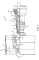
- the high pressure compressor 200 includes a plurality of rotors 202 (e.g., rotors R1-R8), each having a rim 204, a disk 206 and a bore 208.
- Each of the plurality of rotors 202 is disposed on or connected to a high speed spool 210 configured to rotate about an engine central longitudinal axis A.
- a rotor blade 212 is secured to the rim 204 of each of the plurality of rotors 202, while a vane 214 is disposed between adjacent pairs of rotor blades.
- each of the plurality of component cooling fluid transfer tubes 236 may be oriented within the manifold 238 to have an axial component (A) and a circumferential component (C), such that the vector components of the thermal management flow F also include axial and circumferential components.
- the axial and circumferential components are with respect to a radial (R), axial (A), and circumferential (C) coordinate system, as illustrated in FIG. 2B , where the axial component (A) is aligned with the engine central longitudinal axis A.
- the thermal management flow F may be oriented to exit each of the plurality of component cooling fluid transfer tubes 236 in a substantially tangential manner relative to the rim section 232, which is rotating during operation of the high pressure compressor 200.
- the thermal management flow F may be diverted from a component cooling fluid source, such as, for example, the core flow C at a plenum section 270 that exists downstream of the plurality of exhaust guide vanes 215 and upstream of a pre-diffuser 242 to a combustor section, such as, for example, the combustor section 26 described above with reference to FIG. 1 .
- the thermal management flow F may also be diverted from a component cooling fluid source outside the core flow C, such as, for example, a source positioned within the bypass flow B, described above with reference to FIG. 1 .
- the one or more plenum cooling passageways may comprise tubes extending through or about other components of the high pressure compressor 200 that do not include one or more of the plurality of exhaust guide vanes 215. These and other embodiments are described further below with reference to FIGS. 3 and 4 .
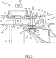
- the tangential onboard injector system 334 shares many of the structural details and characteristics of the tangential onboard injector system 234 described above with reference to FIGS. 2A and 2B and, accordingly, such structural details and characteristics are not repeated here.
- Rach of the plurality of component cooling fluid transfer tubes 336 may be oriented within the manifold 338 to produce a thermal management flow F.
- the thermal management flow F may be oriented to exit each of the plurality of component cooling fluid transfer tubes 336 in a substantially tangential manner relative to a rim section 332, which is rotating during operation of the high pressure compressor 300.
- a plenum cooling fluid CF may be circulated within the plenum 340 defined by the manifold 338 in order to cool the thermal management flow F.
- the plenum cooling fluid CF is routed to and from the manifold 338 by one or more passageways 344 which may extend through one or more of the plurality of exhaust guide vanes 315.
- the plenum cooling fluid CF may be diverted from an upstream stage 350 of the high pressure compressor 300.
- the upstream stage 350 of the high pressure compressor 300 may comprise a region downstream of a stator S6 and upstream of a rotor R7, where such region has a similar counterpart to the region between the stator S6 and the rotor R7 described above with reference to FIG. 2A .
- the upstream stage 350 may reside at any point of the high pressure compressor 300 where cooling flow may be bled from the core flow C.
- the plenum cooling fluid CF that is bled or diverted from the core flow C at the upstream stage 350 of the high pressure compressor 300 may be diverted additionally through a heat exchanger 352, which may be disposed within a bypass flow, such as, for example, the bypass flow B described above with reference to FIG. 1 .
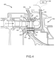
- the high pressure compressor 400 includes a thermal management system 430, such as, for example, the thermal management system 230 described above with reference to FIGS. 2A and 2B .
- the thermal management system 430 includes a tangential onboard injector system 434, that itself includes a plurality of component cooling fluid transfer tubes 436 disposed within a manifold 438 that defines a plenum 440 that extends circumferentially about an engine central longitudinal axis A and surrounds each of the plurality of component cooling fluid transfer tubes 436.
- the tangential onboard injector system 434 shares many of the structural details and characteristics of the tangential onboard injector system 234 described above with reference to FIGS.
- Each of the plurality of component cooling fluid transfer tubes 436 may be oriented within the manifold 438 to produce a thermal management flow F.
- the thermal management flow F may be oriented to exit each of the plurality of component cooling fluid transfer tubes 436 in a substantially tangential manner relative to a rim section 432, which is rotating during operation of the high pressure compressor 400.
- references to "one embodiment,” “an embodiment,” “various embodiments,” etc. indicate that the embodiment described may include a particular feature, structure, or characteristic, but every embodiment may not necessarily include the particular feature, structure, or characteristic. Moreover, such phrases are not necessarily referring to the same embodiment. Further, when a particular feature, structure, or characteristic is described in connection with an embodiment, it is submitted that it is within the knowledge of one skilled in the art to affect such feature, structure, or characteristic in connection with other embodiments whether or not explicitly described. After reading the description, it will be apparent to one skilled in the relevant art(s) how to implement the disclosure in alternative embodiments.
Landscapes
- Engineering & Computer Science (AREA)
- Mechanical Engineering (AREA)
- General Engineering & Computer Science (AREA)
- Chemical & Material Sciences (AREA)
- Combustion & Propulsion (AREA)
- Physics & Mathematics (AREA)
- Fluid Mechanics (AREA)
- Structures Of Non-Positive Displacement Pumps (AREA)
Claims (9)
- Système de gestion thermique (230 ; 330 ; 430) pour un composant d'un moteur à turbine à gaz (20) comprenant :un collecteur (238 ; 338 ; 438) s'étendant circonférentiellement autour d'un axe longitudinal (A) et définissant un plénum (240 ; 340 ; 440) ;un tube de transfert de fluide de refroidissement (236 ; 336 ; 436) disposé à l'intérieur du plénum et conçu pour transférer un fluide de refroidissement de composant depuis une source de fluide de refroidissement de composant vers le composant ; et un passage de fluide de refroidissement (244 ; 344 ; 444) relié au collecteur et conçu pour transférer un fluide de refroidissement (CF) de plénum depuis une source de fluide de refroidissement de plénum vers le plénum,caractérisé en ce que le tube de transfert de fluide de refroidissement comporte une première extrémité de tube de refroidissement axiale (246) et une seconde extrémité de tube de refroidissement axiale (248).
- Système de gestion thermique (230 ; 330 ; 430) selon la revendication 1, dans lequel le composant est une section de jante (232 ; 332 ; 432) d'un rotor (R8) d'un compresseur haute pression (200).
- Système de gestion thermique (230 ; 330 ; 430) selon la revendication 2, dans lequel la source de fluide de refroidissement de composant est disposée à l'intérieur un écoulement central du compresseur haute pression (200).
- Système de gestion thermique (230 ; 330 ; 430) selon la revendication 3, dans lequel la source de fluide de refroidissement de composant est une section de plénum (270 ; 370) disposée en aval d'une aube directrice d'échappement (215 ; 315 ; 415).
- Système de gestion thermique (230 ; 330 ; 430) selon la revendication 3, dans lequel la source de fluide de refroidissement de composant est disposée à l'intérieur d'un flux de dérivation (B) du moteur à turbine à gaz (20).
- Système de gestion thermique (230 ; 330 ; 430) selon l'une quelconque des revendications 2 à 5, dans lequel le passage de fluide de refroidissement (244 ; 344 ; 444) s'étend à travers une aube directrice d'échappement (215 ; 315 ; 415).
- Système de gestion thermique (230 ; 330 ; 430) selon la revendication 6, dans lequel la source de fluide de refroidissement de plénum est disposée à l'intérieur un écoulement central du compresseur haute pression (200).
- Système de gestion thermique (230 ; 330 ; 430) selon la revendication 7, dans lequel la source de fluide de refroidissement de plénum est disposée en amont du rotor (R8).
- Système de gestion thermique (230 ; 330 ; 430) selon la revendication 3 ou 7, dans lequel la source de fluide de refroidissement de plénum est disposée à l'intérieur d'un écoulement de dérivation (B) du moteur à turbine à gaz (20).
Applications Claiming Priority (2)
| Application Number | Priority Date | Filing Date | Title |
|---|---|---|---|
| US16/177,991 US10927706B2 (en) | 2018-11-01 | 2018-11-01 | Intercooled tangential air injector for gas turbine engines |
| EP19204521.9A EP3647542B1 (fr) | 2018-11-01 | 2019-10-22 | Injecteur d'air tangentiel à refroidissement intermédiaire pour moteurs à turbine à gaz |
Related Parent Applications (2)
| Application Number | Title | Priority Date | Filing Date |
|---|---|---|---|
| EP19204521.9A Division-Into EP3647542B1 (fr) | 2018-11-01 | 2019-10-22 | Injecteur d'air tangentiel à refroidissement intermédiaire pour moteurs à turbine à gaz |
| EP19204521.9A Division EP3647542B1 (fr) | 2018-11-01 | 2019-10-22 | Injecteur d'air tangentiel à refroidissement intermédiaire pour moteurs à turbine à gaz |
Publications (2)
| Publication Number | Publication Date |
|---|---|
| EP3901411A1 EP3901411A1 (fr) | 2021-10-27 |
| EP3901411B1 true EP3901411B1 (fr) | 2024-07-03 |
Family
ID=68296364
Family Applications (2)
| Application Number | Title | Priority Date | Filing Date |
|---|---|---|---|
| EP21170439.0A Active EP3901411B1 (fr) | 2018-11-01 | 2019-10-22 | Système de gestion thermique pour un composant d'un moteur à turbine à gaz |
| EP19204521.9A Active EP3647542B1 (fr) | 2018-11-01 | 2019-10-22 | Injecteur d'air tangentiel à refroidissement intermédiaire pour moteurs à turbine à gaz |
Family Applications After (1)
| Application Number | Title | Priority Date | Filing Date |
|---|---|---|---|
| EP19204521.9A Active EP3647542B1 (fr) | 2018-11-01 | 2019-10-22 | Injecteur d'air tangentiel à refroidissement intermédiaire pour moteurs à turbine à gaz |
Country Status (2)
| Country | Link |
|---|---|
| US (1) | US10927706B2 (fr) |
| EP (2) | EP3901411B1 (fr) |
Family Cites Families (15)
| Publication number | Priority date | Publication date | Assignee | Title |
|---|---|---|---|---|
| FR1093301A (fr) | 1953-02-17 | 1955-05-03 | ||
| SE395747B (sv) * | 1975-12-10 | 1977-08-22 | Stal Laval Turbin Ab | Tvastegsgasturbin |
| US4822244A (en) | 1987-10-15 | 1989-04-18 | United Technologies Corporation | Tobi |
| US5685158A (en) | 1995-03-31 | 1997-11-11 | General Electric Company | Compressor rotor cooling system for a gas turbine |
| US6183193B1 (en) | 1999-05-21 | 2001-02-06 | Pratt & Whitney Canada Corp. | Cast on-board injection nozzle with adjustable flow area |
| US20080041064A1 (en) | 2006-08-17 | 2008-02-21 | United Technologies Corporation | Preswirl pollution air handling with tangential on-board injector for turbine rotor cooling |
| GB0818047D0 (en) | 2008-10-03 | 2008-11-05 | Rolls Royce Plc | Turbine cooling system |
| US8381533B2 (en) | 2009-04-30 | 2013-02-26 | Honeywell International Inc. | Direct transfer axial tangential onboard injector system (TOBI) with self-supporting seal plate |
| US9382810B2 (en) | 2012-07-27 | 2016-07-05 | General Electric Company | Closed loop cooling system for a gas turbine |
| US9125681B2 (en) | 2012-09-26 | 2015-09-08 | Ethicon Endo-Surgery, Inc. | Detachable end effector and loader |
| DE102013217504A1 (de) | 2013-09-03 | 2015-03-05 | MTU Aero Engines AG | Strömungsmaschine |
| US9777634B2 (en) | 2013-09-12 | 2017-10-03 | United Technologies Corporation | Tube fed tangential on-board injector for gas turbine engine |
| US9927123B2 (en) | 2013-10-24 | 2018-03-27 | United Technologies Corporation | Fluid transport system having divided transport tube |
| EP3090163B1 (fr) * | 2013-12-30 | 2018-02-21 | United Technologies Corporation | Gestion thermique de tambour de compresseur |
| US10961911B2 (en) | 2017-01-17 | 2021-03-30 | Raytheon Technologies Corporation | Injection cooled cooling air system for a gas turbine engine |
-
2018
- 2018-11-01 US US16/177,991 patent/US10927706B2/en active Active
-
2019
- 2019-10-22 EP EP21170439.0A patent/EP3901411B1/fr active Active
- 2019-10-22 EP EP19204521.9A patent/EP3647542B1/fr active Active
Also Published As
| Publication number | Publication date |
|---|---|
| EP3647542B1 (fr) | 2021-07-07 |
| US20200141272A1 (en) | 2020-05-07 |
| US10927706B2 (en) | 2021-02-23 |
| EP3901411A1 (fr) | 2021-10-27 |
| EP3647542A1 (fr) | 2020-05-06 |
Similar Documents
| Publication | Publication Date | Title |
|---|---|---|
| US10612383B2 (en) | Compressor aft rotor rim cooling for high OPR (T3) engine | |
| EP2075437B1 (fr) | Système de refroidissement à plusieurs sources pour une turbine à gaz | |
| US11060530B2 (en) | Compressor cooling in a gas turbine engine | |
| US20170292532A1 (en) | Compressor secondary flow aft cone cooling scheme | |
| EP2855884A1 (fr) | Système d'alimentation en réfrigérant pour turbine à haute pression | |
| US11377957B2 (en) | Gas turbine engine with a diffuser cavity cooled compressor | |
| US11976562B2 (en) | System for controlling blade clearances within a gas turbine engine | |
| US9435259B2 (en) | Gas turbine engine cooling system | |
| CN106050314A (zh) | 涡轮框架和用于涡轮框架的翼型件 | |
| US10934845B2 (en) | Dual cooling airflow to blades | |
| US20180058329A1 (en) | Multi-air stream cooling system | |
| CA2965268A1 (fr) | Deflecteur de tourbillon installe sur une helice | |
| EP3508688B1 (fr) | Moteur à turbine à gaz et compresseur | |
| US20240352942A1 (en) | Tandem blade rotor disk | |
| US10415465B2 (en) | Axial compressor with inter-stage centrifugal compressor | |
| EP3647542B1 (fr) | Injecteur d'air tangentiel à refroidissement intermédiaire pour moteurs à turbine à gaz | |
| US11215056B2 (en) | Thermally isolated rotor systems and methods | |
| US12624642B2 (en) | Low-pressure turbine | |
| EP3392472B1 (fr) | Section de compresseur pour un moteur à turbine à gaz, moteur à turbine à gaz et procédé de fonctionnement d'une section de compresseur dans un moteur à turbine à gaz, associés | |
| CN118815592A (zh) | 主动间隙控制组件 |
Legal Events
| Date | Code | Title | Description |
|---|---|---|---|
| PUAI | Public reference made under article 153(3) epc to a published international application that has entered the european phase |
Free format text: ORIGINAL CODE: 0009012 |
|
| STAA | Information on the status of an ep patent application or granted ep patent |
Free format text: STATUS: THE APPLICATION HAS BEEN PUBLISHED |
|
| AC | Divisional application: reference to earlier application |
Ref document number: 3647542 Country of ref document: EP Kind code of ref document: P |
|
| AK | Designated contracting states |
Kind code of ref document: A1 Designated state(s): AL AT BE BG CH CY CZ DE DK EE ES FI FR GB GR HR HU IE IS IT LI LT LU LV MC MK MT NL NO PL PT RO RS SE SI SK SM TR |
|
| B565 | Issuance of search results under rule 164(2) epc |
Effective date: 20210923 |
|
| STAA | Information on the status of an ep patent application or granted ep patent |
Free format text: STATUS: REQUEST FOR EXAMINATION WAS MADE |
|
| 17P | Request for examination filed |
Effective date: 20220427 |
|
| RBV | Designated contracting states (corrected) |
Designated state(s): AL AT BE BG CH CY CZ DE DK EE ES FI FR GB GR HR HU IE IS IT LI LT LU LV MC MK MT NL NO PL PT RO RS SE SI SK SM TR |
|
| STAA | Information on the status of an ep patent application or granted ep patent |
Free format text: STATUS: EXAMINATION IS IN PROGRESS |
|
| 17Q | First examination report despatched |
Effective date: 20230309 |
|
| RAP3 | Party data changed (applicant data changed or rights of an application transferred) |
Owner name: RTX CORPORATION |
|
| GRAP | Despatch of communication of intention to grant a patent |
Free format text: ORIGINAL CODE: EPIDOSNIGR1 |
|
| STAA | Information on the status of an ep patent application or granted ep patent |
Free format text: STATUS: GRANT OF PATENT IS INTENDED |
|
| INTG | Intention to grant announced |
Effective date: 20240202 |
|
| GRAS | Grant fee paid |
Free format text: ORIGINAL CODE: EPIDOSNIGR3 |
|
| GRAA | (expected) grant |
Free format text: ORIGINAL CODE: 0009210 |
|
| STAA | Information on the status of an ep patent application or granted ep patent |
Free format text: STATUS: THE PATENT HAS BEEN GRANTED |
|
| AC | Divisional application: reference to earlier application |
Ref document number: 3647542 Country of ref document: EP Kind code of ref document: P |
|
| AK | Designated contracting states |
Kind code of ref document: B1 Designated state(s): AL AT BE BG CH CY CZ DE DK EE ES FI FR GB GR HR HU IE IS IT LI LT LU LV MC MK MT NL NO PL PT RO RS SE SI SK SM TR |
|
| REG | Reference to a national code |
Ref country code: CH Ref legal event code: EP |
|
| REG | Reference to a national code |
Ref country code: DE Ref legal event code: R096 Ref document number: 602019054844 Country of ref document: DE |
|
| REG | Reference to a national code |
Ref country code: LT Ref legal event code: MG9D |
|
| REG | Reference to a national code |
Ref country code: NL Ref legal event code: MP Effective date: 20240703 |
|
| PG25 | Lapsed in a contracting state [announced via postgrant information from national office to epo] |
Ref country code: PT Free format text: LAPSE BECAUSE OF FAILURE TO SUBMIT A TRANSLATION OF THE DESCRIPTION OR TO PAY THE FEE WITHIN THE PRESCRIBED TIME-LIMIT Effective date: 20241104 |
|
| REG | Reference to a national code |
Ref country code: AT Ref legal event code: MK05 Ref document number: 1700004 Country of ref document: AT Kind code of ref document: T Effective date: 20240703 |
|
| PG25 | Lapsed in a contracting state [announced via postgrant information from national office to epo] |
Ref country code: NL Free format text: LAPSE BECAUSE OF FAILURE TO SUBMIT A TRANSLATION OF THE DESCRIPTION OR TO PAY THE FEE WITHIN THE PRESCRIBED TIME-LIMIT Effective date: 20240703 |
|
| PG25 | Lapsed in a contracting state [announced via postgrant information from national office to epo] |
Ref country code: PT Free format text: LAPSE BECAUSE OF FAILURE TO SUBMIT A TRANSLATION OF THE DESCRIPTION OR TO PAY THE FEE WITHIN THE PRESCRIBED TIME-LIMIT Effective date: 20241104 Ref country code: NL Free format text: LAPSE BECAUSE OF FAILURE TO SUBMIT A TRANSLATION OF THE DESCRIPTION OR TO PAY THE FEE WITHIN THE PRESCRIBED TIME-LIMIT Effective date: 20240703 |
|
| PG25 | Lapsed in a contracting state [announced via postgrant information from national office to epo] |
Ref country code: NO Free format text: LAPSE BECAUSE OF FAILURE TO SUBMIT A TRANSLATION OF THE DESCRIPTION OR TO PAY THE FEE WITHIN THE PRESCRIBED TIME-LIMIT Effective date: 20241003 |
|
| PG25 | Lapsed in a contracting state [announced via postgrant information from national office to epo] |
Ref country code: FI Free format text: LAPSE BECAUSE OF FAILURE TO SUBMIT A TRANSLATION OF THE DESCRIPTION OR TO PAY THE FEE WITHIN THE PRESCRIBED TIME-LIMIT Effective date: 20240703 Ref country code: GR Free format text: LAPSE BECAUSE OF FAILURE TO SUBMIT A TRANSLATION OF THE DESCRIPTION OR TO PAY THE FEE WITHIN THE PRESCRIBED TIME-LIMIT Effective date: 20241004 Ref country code: PL Free format text: LAPSE BECAUSE OF FAILURE TO SUBMIT A TRANSLATION OF THE DESCRIPTION OR TO PAY THE FEE WITHIN THE PRESCRIBED TIME-LIMIT Effective date: 20240703 |
|
| PG25 | Lapsed in a contracting state [announced via postgrant information from national office to epo] |
Ref country code: BG Free format text: LAPSE BECAUSE OF FAILURE TO SUBMIT A TRANSLATION OF THE DESCRIPTION OR TO PAY THE FEE WITHIN THE PRESCRIBED TIME-LIMIT Effective date: 20240703 |
|
| PG25 | Lapsed in a contracting state [announced via postgrant information from national office to epo] |
Ref country code: LV Free format text: LAPSE BECAUSE OF FAILURE TO SUBMIT A TRANSLATION OF THE DESCRIPTION OR TO PAY THE FEE WITHIN THE PRESCRIBED TIME-LIMIT Effective date: 20240703 |
|
| PG25 | Lapsed in a contracting state [announced via postgrant information from national office to epo] |
Ref country code: AT Free format text: LAPSE BECAUSE OF FAILURE TO SUBMIT A TRANSLATION OF THE DESCRIPTION OR TO PAY THE FEE WITHIN THE PRESCRIBED TIME-LIMIT Effective date: 20240703 Ref country code: IS Free format text: LAPSE BECAUSE OF FAILURE TO SUBMIT A TRANSLATION OF THE DESCRIPTION OR TO PAY THE FEE WITHIN THE PRESCRIBED TIME-LIMIT Effective date: 20241103 |
|
| PG25 | Lapsed in a contracting state [announced via postgrant information from national office to epo] |
Ref country code: HR Free format text: LAPSE BECAUSE OF FAILURE TO SUBMIT A TRANSLATION OF THE DESCRIPTION OR TO PAY THE FEE WITHIN THE PRESCRIBED TIME-LIMIT Effective date: 20240703 Ref country code: CZ Free format text: LAPSE BECAUSE OF FAILURE TO SUBMIT A TRANSLATION OF THE DESCRIPTION OR TO PAY THE FEE WITHIN THE PRESCRIBED TIME-LIMIT Effective date: 20240703 |
|
| PG25 | Lapsed in a contracting state [announced via postgrant information from national office to epo] |
Ref country code: RS Free format text: LAPSE BECAUSE OF FAILURE TO SUBMIT A TRANSLATION OF THE DESCRIPTION OR TO PAY THE FEE WITHIN THE PRESCRIBED TIME-LIMIT Effective date: 20241003 Ref country code: ES Free format text: LAPSE BECAUSE OF FAILURE TO SUBMIT A TRANSLATION OF THE DESCRIPTION OR TO PAY THE FEE WITHIN THE PRESCRIBED TIME-LIMIT Effective date: 20240703 |
|
| PG25 | Lapsed in a contracting state [announced via postgrant information from national office to epo] |
Ref country code: RS Free format text: LAPSE BECAUSE OF FAILURE TO SUBMIT A TRANSLATION OF THE DESCRIPTION OR TO PAY THE FEE WITHIN THE PRESCRIBED TIME-LIMIT Effective date: 20241003 Ref country code: PL Free format text: LAPSE BECAUSE OF FAILURE TO SUBMIT A TRANSLATION OF THE DESCRIPTION OR TO PAY THE FEE WITHIN THE PRESCRIBED TIME-LIMIT Effective date: 20240703 Ref country code: NO Free format text: LAPSE BECAUSE OF FAILURE TO SUBMIT A TRANSLATION OF THE DESCRIPTION OR TO PAY THE FEE WITHIN THE PRESCRIBED TIME-LIMIT Effective date: 20241003 Ref country code: LV Free format text: LAPSE BECAUSE OF FAILURE TO SUBMIT A TRANSLATION OF THE DESCRIPTION OR TO PAY THE FEE WITHIN THE PRESCRIBED TIME-LIMIT Effective date: 20240703 Ref country code: IS Free format text: LAPSE BECAUSE OF FAILURE TO SUBMIT A TRANSLATION OF THE DESCRIPTION OR TO PAY THE FEE WITHIN THE PRESCRIBED TIME-LIMIT Effective date: 20241103 Ref country code: HR Free format text: LAPSE BECAUSE OF FAILURE TO SUBMIT A TRANSLATION OF THE DESCRIPTION OR TO PAY THE FEE WITHIN THE PRESCRIBED TIME-LIMIT Effective date: 20240703 Ref country code: GR Free format text: LAPSE BECAUSE OF FAILURE TO SUBMIT A TRANSLATION OF THE DESCRIPTION OR TO PAY THE FEE WITHIN THE PRESCRIBED TIME-LIMIT Effective date: 20241004 Ref country code: FI Free format text: LAPSE BECAUSE OF FAILURE TO SUBMIT A TRANSLATION OF THE DESCRIPTION OR TO PAY THE FEE WITHIN THE PRESCRIBED TIME-LIMIT Effective date: 20240703 Ref country code: ES Free format text: LAPSE BECAUSE OF FAILURE TO SUBMIT A TRANSLATION OF THE DESCRIPTION OR TO PAY THE FEE WITHIN THE PRESCRIBED TIME-LIMIT Effective date: 20240703 Ref country code: CZ Free format text: LAPSE BECAUSE OF FAILURE TO SUBMIT A TRANSLATION OF THE DESCRIPTION OR TO PAY THE FEE WITHIN THE PRESCRIBED TIME-LIMIT Effective date: 20240703 Ref country code: BG Free format text: LAPSE BECAUSE OF FAILURE TO SUBMIT A TRANSLATION OF THE DESCRIPTION OR TO PAY THE FEE WITHIN THE PRESCRIBED TIME-LIMIT Effective date: 20240703 Ref country code: AT Free format text: LAPSE BECAUSE OF FAILURE TO SUBMIT A TRANSLATION OF THE DESCRIPTION OR TO PAY THE FEE WITHIN THE PRESCRIBED TIME-LIMIT Effective date: 20240703 |
|
| REG | Reference to a national code |
Ref country code: DE Ref legal event code: R097 Ref document number: 602019054844 Country of ref document: DE |
|
| PG25 | Lapsed in a contracting state [announced via postgrant information from national office to epo] |
Ref country code: RO Free format text: LAPSE BECAUSE OF FAILURE TO SUBMIT A TRANSLATION OF THE DESCRIPTION OR TO PAY THE FEE WITHIN THE PRESCRIBED TIME-LIMIT Effective date: 20240703 Ref country code: DK Free format text: LAPSE BECAUSE OF FAILURE TO SUBMIT A TRANSLATION OF THE DESCRIPTION OR TO PAY THE FEE WITHIN THE PRESCRIBED TIME-LIMIT Effective date: 20240703 Ref country code: SM Free format text: LAPSE BECAUSE OF FAILURE TO SUBMIT A TRANSLATION OF THE DESCRIPTION OR TO PAY THE FEE WITHIN THE PRESCRIBED TIME-LIMIT Effective date: 20240703 |
|
| PG25 | Lapsed in a contracting state [announced via postgrant information from national office to epo] |
Ref country code: EE Free format text: LAPSE BECAUSE OF FAILURE TO SUBMIT A TRANSLATION OF THE DESCRIPTION OR TO PAY THE FEE WITHIN THE PRESCRIBED TIME-LIMIT Effective date: 20240703 |
|
| PG25 | Lapsed in a contracting state [announced via postgrant information from national office to epo] |
Ref country code: SK Free format text: LAPSE BECAUSE OF FAILURE TO SUBMIT A TRANSLATION OF THE DESCRIPTION OR TO PAY THE FEE WITHIN THE PRESCRIBED TIME-LIMIT Effective date: 20240703 Ref country code: IT Free format text: LAPSE BECAUSE OF FAILURE TO SUBMIT A TRANSLATION OF THE DESCRIPTION OR TO PAY THE FEE WITHIN THE PRESCRIBED TIME-LIMIT Effective date: 20240703 |
|
| PLBE | No opposition filed within time limit |
Free format text: ORIGINAL CODE: 0009261 |
|
| STAA | Information on the status of an ep patent application or granted ep patent |
Free format text: STATUS: NO OPPOSITION FILED WITHIN TIME LIMIT |
|
| REG | Reference to a national code |
Ref country code: CH Ref legal event code: PL |
|
| 26N | No opposition filed |
Effective date: 20250404 |
|
| PG25 | Lapsed in a contracting state [announced via postgrant information from national office to epo] |
Ref country code: MC Free format text: LAPSE BECAUSE OF FAILURE TO SUBMIT A TRANSLATION OF THE DESCRIPTION OR TO PAY THE FEE WITHIN THE PRESCRIBED TIME-LIMIT Effective date: 20240703 |
|
| PG25 | Lapsed in a contracting state [announced via postgrant information from national office to epo] |
Ref country code: LU Free format text: LAPSE BECAUSE OF NON-PAYMENT OF DUE FEES Effective date: 20241022 Ref country code: BE Free format text: LAPSE BECAUSE OF NON-PAYMENT OF DUE FEES Effective date: 20241031 |
|
| PG25 | Lapsed in a contracting state [announced via postgrant information from national office to epo] |
Ref country code: CH Free format text: LAPSE BECAUSE OF NON-PAYMENT OF DUE FEES Effective date: 20241031 |
|
| REG | Reference to a national code |
Ref country code: BE Ref legal event code: MM Effective date: 20241031 |
|
| PG25 | Lapsed in a contracting state [announced via postgrant information from national office to epo] |
Ref country code: SE Free format text: LAPSE BECAUSE OF FAILURE TO SUBMIT A TRANSLATION OF THE DESCRIPTION OR TO PAY THE FEE WITHIN THE PRESCRIBED TIME-LIMIT Effective date: 20240703 |
|
| PGFP | Annual fee paid to national office [announced via postgrant information from national office to epo] |
Ref country code: GB Payment date: 20250923 Year of fee payment: 7 |
|
| PGFP | Annual fee paid to national office [announced via postgrant information from national office to epo] |
Ref country code: FR Payment date: 20250924 Year of fee payment: 7 |
|
| PG25 | Lapsed in a contracting state [announced via postgrant information from national office to epo] |
Ref country code: IE Free format text: LAPSE BECAUSE OF NON-PAYMENT OF DUE FEES Effective date: 20241022 |
|
| PGFP | Annual fee paid to national office [announced via postgrant information from national office to epo] |
Ref country code: DE Payment date: 20250923 Year of fee payment: 7 |
|
| PG25 | Lapsed in a contracting state [announced via postgrant information from national office to epo] |
Ref country code: CY Free format text: LAPSE BECAUSE OF FAILURE TO SUBMIT A TRANSLATION OF THE DESCRIPTION OR TO PAY THE FEE WITHIN THE PRESCRIBED TIME-LIMIT; INVALID AB INITIO Effective date: 20191022 |
|
| PG25 | Lapsed in a contracting state [announced via postgrant information from national office to epo] |
Ref country code: HU Free format text: LAPSE BECAUSE OF FAILURE TO SUBMIT A TRANSLATION OF THE DESCRIPTION OR TO PAY THE FEE WITHIN THE PRESCRIBED TIME-LIMIT; INVALID AB INITIO Effective date: 20191022 |