EP3901529B1 - Entfeuchter - Google Patents
Entfeuchter Download PDFInfo
- Publication number
- EP3901529B1 EP3901529B1 EP20888725.7A EP20888725A EP3901529B1 EP 3901529 B1 EP3901529 B1 EP 3901529B1 EP 20888725 A EP20888725 A EP 20888725A EP 3901529 B1 EP3901529 B1 EP 3901529B1
- Authority
- EP
- European Patent Office
- Prior art keywords
- side wall
- filter net
- filter
- machine body
- mounting port
- Prior art date
- Legal status (The legal status is an assumption and is not a legal conclusion. Google has not performed a legal analysis and makes no representation as to the accuracy of the status listed.)
- Active
Links
Images



Classifications
-
- F—MECHANICAL ENGINEERING; LIGHTING; HEATING; WEAPONS; BLASTING
- F24—HEATING; RANGES; VENTILATING
- F24F—AIR-CONDITIONING; AIR-HUMIDIFICATION; VENTILATION; USE OF AIR CURRENTS FOR SCREENING
- F24F13/00—Details common to, or for air-conditioning, air-humidification, ventilation or use of air currents for screening
- F24F13/20—Casings or covers
-
- F—MECHANICAL ENGINEERING; LIGHTING; HEATING; WEAPONS; BLASTING
- F24—HEATING; RANGES; VENTILATING
- F24F—AIR-CONDITIONING; AIR-HUMIDIFICATION; VENTILATION; USE OF AIR CURRENTS FOR SCREENING
- F24F1/00—Room units for air-conditioning, e.g. separate or self-contained units or units receiving primary air from a central station
- F24F1/02—Self-contained room units for air-conditioning, i.e. with all apparatus for treatment installed in a common casing
- F24F1/0328—Self-contained room units for air-conditioning, i.e. with all apparatus for treatment installed in a common casing with means for purifying supplied air
- F24F1/035—Self-contained room units for air-conditioning, i.e. with all apparatus for treatment installed in a common casing with means for purifying supplied air characterised by the mounting or arrangement of filters
-
- F—MECHANICAL ENGINEERING; LIGHTING; HEATING; WEAPONS; BLASTING
- F24—HEATING; RANGES; VENTILATING
- F24F—AIR-CONDITIONING; AIR-HUMIDIFICATION; VENTILATION; USE OF AIR CURRENTS FOR SCREENING
- F24F1/00—Room units for air-conditioning, e.g. separate or self-contained units or units receiving primary air from a central station
- F24F1/02—Self-contained room units for air-conditioning, i.e. with all apparatus for treatment installed in a common casing
- F24F1/0358—Self-contained room units for air-conditioning, i.e. with all apparatus for treatment installed in a common casing with dehumidification means
-
- F—MECHANICAL ENGINEERING; LIGHTING; HEATING; WEAPONS; BLASTING
- F24—HEATING; RANGES; VENTILATING
- F24F—AIR-CONDITIONING; AIR-HUMIDIFICATION; VENTILATION; USE OF AIR CURRENTS FOR SCREENING
- F24F13/00—Details common to, or for air-conditioning, air-humidification, ventilation or use of air currents for screening
- F24F13/28—Arrangement or mounting of filters
-
- F—MECHANICAL ENGINEERING; LIGHTING; HEATING; WEAPONS; BLASTING
- F24—HEATING; RANGES; VENTILATING
- F24F—AIR-CONDITIONING; AIR-HUMIDIFICATION; VENTILATION; USE OF AIR CURRENTS FOR SCREENING
- F24F2221/00—Details or features not otherwise provided for
- F24F2221/12—Details or features not otherwise provided for transportable
-
- F—MECHANICAL ENGINEERING; LIGHTING; HEATING; WEAPONS; BLASTING
- F24—HEATING; RANGES; VENTILATING
- F24F—AIR-CONDITIONING; AIR-HUMIDIFICATION; VENTILATION; USE OF AIR CURRENTS FOR SCREENING
- F24F2221/00—Details or features not otherwise provided for
- F24F2221/32—Details or features not otherwise provided for preventing human errors during the installation, use or maintenance, e.g. goofy proof
-
- F—MECHANICAL ENGINEERING; LIGHTING; HEATING; WEAPONS; BLASTING
- F24—HEATING; RANGES; VENTILATING
- F24F—AIR-CONDITIONING; AIR-HUMIDIFICATION; VENTILATION; USE OF AIR CURRENTS FOR SCREENING
- F24F3/00—Air-conditioning systems in which conditioned primary air is supplied from one or more central stations to distributing units in the rooms or spaces where it may receive secondary treatment; Apparatus specially designed for such systems
- F24F3/12—Air-conditioning systems in which conditioned primary air is supplied from one or more central stations to distributing units in the rooms or spaces where it may receive secondary treatment; Apparatus specially designed for such systems characterised by the treatment of the air otherwise than by heating and cooling
- F24F3/14—Air-conditioning systems in which conditioned primary air is supplied from one or more central stations to distributing units in the rooms or spaces where it may receive secondary treatment; Apparatus specially designed for such systems characterised by the treatment of the air otherwise than by heating and cooling by humidification; by dehumidification
-
- F—MECHANICAL ENGINEERING; LIGHTING; HEATING; WEAPONS; BLASTING
- F24—HEATING; RANGES; VENTILATING
- F24F—AIR-CONDITIONING; AIR-HUMIDIFICATION; VENTILATION; USE OF AIR CURRENTS FOR SCREENING
- F24F8/00—Treatment, e.g. purification, of air supplied to human living or working spaces otherwise than by heating, cooling, humidifying or drying
- F24F8/10—Treatment, e.g. purification, of air supplied to human living or working spaces otherwise than by heating, cooling, humidifying or drying by separation, e.g. by filtering
Definitions
- the application relates to the technical field of dehumidification equipments, in particular to a dehumidifier.
- a filter net is usually configured at the air inlet to filter the air entering the dehumidifier.
- a filter net is usually configured inside a machine body.
- a shell of the machine body usually needs to be disassembled to disassemble the filter net, resulting in complicated disassembly and assembly process of cleaning or replacing the filter net, which affects the user experience.
- the dehumidifier comprises a machine body.
- the machine body comprises a shell, a condenser, an evaporator, an axial flow fan and a water collecting plate, wherein the shell is provided with an air inlet and an air outlet, the condenser and the evaporator are arranged in the shell, the axial flow fan is vertically arranged in the shell and is parallel to the condenser and the evaporator, the water collecting plate is arranged under the condenser, and the evaporator and the axial flow fan and divides the interior of the shell into an axial flow air duct and a containing cavity.
- the compactness of the structure can be easily improved.
- Prior art document WO 2019/214154 A1 discloses a housing assembly and a dehumidifier.
- the housing assembly comprises a housing and an air inlet grid.
- the housing comprises a first face, a second face and a third face, which are successively connected to each other, the first face being arranged opposite the third face; and the housing is further provided with an air outlet opposite the second face.
- the air inlet grid comprises a first air inlet grid arranged on the first face, a second air inlet grid arranged on the second face, and a third air inlet grid arranged on the third face, wherein the first air inlet grid, the second air inlet grid and the third air inlet grid are respectively provided with a filter screen; at least one of the first air inlet grid, the second air inlet grid and the third air inlet grid is provided with a filter screen insertion groove; and a corresponding filter screen is inserted into the filter screen insertion groove in a drawable manner.
- the main purpose of the present application is to provide a dehumidifier, aiming at improving convenience of disassembly and assembly for cleaning or replacing a filter net.
- a dehumidifier including:
- the filter net slot is configured in the machine body, and the side wall is defined with a filter net mounting port for inserting the filter net.
- two parallel upper guide rails are provided on and protrude from the top cover at intervals to form the upper slot between the two upper guide rails; and/or, two parallel lower guide rails are provided on and protrude from the water receiving tray at intervals to form the lower slot between the two lower guide rails.
- the side wall includes a first side wall, a second side wall, and a third side wall being connected in sequence, the first side wall is opposite to the third side wall, each of the first side wall, the second side wall, and the third side wall is defined with an air inlet.
- the filter net includes two filter subnets spliced in a circumferential direction of the machine body, one of the two filter subnets covers the air inlet on the first side wall and a portion of the air inlet on the second side wall, and the other one of the two filter subnets covers another portion of the air inlet on the second side wall and the air inlet on the third side wall; and each of the first side wall and the third side wall is defined with a filter net mounting port for loading the two filter subnets respectively.
- one end of each of the two filter subnets is configured with a blocking member, and another end of each of the two filter subnets is inserted into the filter net slot from the filter net mounting port until the blocking member blocks the filter net mounting port.
- the blocking member is configured with a clasp, the clasp being formed in a recessed manner.
- an anti-disengagement structure is provided between each of the two filter subnets and the machine body.
- the anti-disengagement structure includes a buckle hole configured on the filter subnet and a buckle configured on an inner side of the filter net mounting port, and the buckle is suitable to be buckled in the buckle hole to restrict the filter subnet from disengaging from the filter net mounting port.
- the machine body is configured with a protective baffle spaced from the filter net mounting port and opposite to the filter net mounting port.
- a filter net slot is configured beside the air inlet of the machine body for the filter net to be drawably inserted, so that when the filter net is to be cleaned or replaced, an outer shell of the machine body does not need to be disassembled, and only the filter net needs to be disassembled by pulling out the filter net from the filter net slot, so that the filter net is disassembled.
- the machine body is extended out relative to the water tank in the working state, so that the air outlet on the machine body has a higher position, the dehumidified air can be discharged to a higher position, and the dehumidified air can be spread to the whole indoor space faster.
- the machine body In the idle state, the machine body can be accommodated in the water tank as much as possible, so that the overall center of gravity of the dehumidifier is lower, making the placement of the dehumidifier more stable, reducing the falling probability of the dehumidifier, and also reducing the overall occupied space for the dehumidifier to be placed in the idle state, thus facilitating users to place the dehumidifier.
- Label Name Label Name 10 Water tank 20 Machine body 21 Side wall 22 Top cover 23 Water receiving tray 24 Buckle 25 Protective baffle 211 First side wall 212 Second side wall 213 Third side wall 214 Fourth side wall 201 Air inlet 202a Upper Slot 202b Lower Slot 203 Filter net mounting port 221 Upper guide rail 231 Lower guide rail 30 filter net 31 Filter subnet 311 Plugging piece 312 Buckle hand 313 Buckle hole 31a Subnet Ontology 31b Subnet flanging 40 Evaporator 50 Condenser
- the directional indication is only used to explain the relative positional relationship and movement between components under a specific posture (as shown in the drawings). If the specific posture changes, the directional indication will also change accordingly.
- the present application provides a dehumidifier.
- the dehumidifier includes:
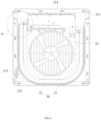
- a filter net slot configured beside the air inlet 201 is configured on the machine body 20 for the filter net 30 to be pulled and inserted, so that when the filter net 30 is to be cleaned or replaced, it is not needed to disassemble a shell of the machine body 20, but only needed to pull the filter net 30 out of the filter net slot to disassemble the filter net 30.
- the convenience of disassembly and assembly to clean or replace the filter net 30 of the dehumidifier is improved, and the user experience is improved.
- the machine body 20 extends out relative to the water tank 10 in the working state, so that an air outlet on the machine body 20 has a higher position, and dehumidified air can be discharged to a higher position and spread to a whole indoor space faster.
- the machine body 20 can be accommodated in the water tank 10 as much as possible, so that an overall center of gravity of the dehumidifier is lower, making a placement of the dehumidifier more stable, reducing probability of falling of the dehumidifier, and also reducing an overall occupied space for the dehumidifier to be placed in the idle state, and facilitating users to place the dehumidifier.
- the mounting port is configured as an open port, so that a side wall 21 of the water tank 10 can provide a downward guide for reception of the machine body 20, and the open port can facilitate receiving of water droplets formed by dehumidification.
- the present design is not limited to this, in other embodiments, the mounting port may not be provided as an open port.
- the machine body 20 includes the side wall 21.
- the air inlet 201 is provided on the side wall 21.
- the filter net slot includes an upper slot 202a for inserting an upper side of the filter net 30, and a lower slot 202b for inserting a lower side of the filter net 30.
- the filter net slot extends in a transverse direction or substantially in the transverse direction, that is, the filter net 30 is inserted into the filter net slot in a transverse pulling manner, and a user can remove the filter net 30 by applying a transverse pulling force to the filter net 30.
- the filter net slot may extend in an up-and-down direction.
- the filter net slot is configured in the machine body 20, and the side wall 21 is provided with a filter net mounting port 203 for the filter net 30 to be inserted.
- the shell of the machine body 20 it is possible for the shell of the machine body 20 to provide physical protection for the filter net 30.
- the user when cleaning or replacing the filter net 30, the user can pull the filter net 30 out of the filter net slot through the filter net mounting port 203, and insert the filter net 30 into the filter net slot through the filter net mounting port 203 after cleaning or replacing.
- the machine body 20 further includes a top cover 22 connected to an upper end of the side wall 21, and a water receiving tray 23 connected to a lower end of the side wall 21.
- the upper slot 202a is defined on the top cover 22, and the lower slot 202b is defined on the water receiving tray 23. That is, in this embodiment, the air inlet 201, the upper slot 202a, and the lower slot 202b are respectively defined on the side wall 21, the top cover 22, and the water receiving tray 23, and the side wall 21, the top cover 22, and the water receiving tray 23 can be correspondingly processed during preparation, thereby reducing processing complexity of a single component and improving processing efficiency of the product.
- this design is not limited to this.
- the upper slot 202a and the lower slot 202b can be defined at the upper end and the lower end of the side wall 21.
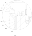
- two upper guide rails 221 are formed on the top cover 22, being parallel to each other and spaced from each other, to form the upper slot 202a between the two upper guide rails 221.
- heights of the upper guide rails 221 can be conveniently set to meet a depth requirement of the upper slot 202a.
- a thickness of the top cover 22 is smaller, thereby saving the material required for the top cover 22 and reducing the cost of the product.
- two lower guide rails 231 are formed on the water receiving tray 23, being parallel to each other and spaced from each other, to form the lower slot 202b between the two lower guide rails 231.
- a depth requirement of the lower slot 202b can be conveniently met by setting heights of the lower guide rails 231.
- a thickness of the water receiving tray 23 is smaller, thereby saving the materials required for the water receiving tray 23 and reducing the cost of the product.
- the side wall 21 includes a first side wall 211, a second side wall 212 and a third side wall 213 being connected in sequence, where the first side wall 211 is opposite to the third side wall 213, and the first side wall 211, the second side wall 212 and the third side wall 213 are all defined with an air inlet 201.
- a "three-sided air inlet" channel can be formed on the machine body 20, and an air treatment area can be increased compared with a "one-sided air inlet” channel, thereby improving the air treatment efficiency.
- the air inlet 201 comprises a plurality of air inlet holes configured in an array.
- this design is not limited to this, in other embodiments, the air inlet 201 may be configured in a grid shape.
- a dehumidification device of the dehumidifier includes a compressor, an evaporator 40 and a condenser 50.
- a dehumidification device of the dehumidifier includes a compressor, an evaporator 40 and a condenser 50.
- water vapor in the air is condensed into water droplets by the evaporator 40 to remove water vapor in the air, and then the air after the water vapor is removed is heated and dried by the condenser 50 to restore blown air to normal temperature.
- the dehumidification device can adopt a dehumidification method such as adsorption type.
- the evaporator 40 is provided with a first evaporation section, a second evaporation section and a third evaporation section corresponding to the air inlet 201 on the first side wall 211, the second side wall 212 and the third side wall 213, respectively.
- the first evaporation section is opposite to the third evaporation section, that is, the evaporator 40 is approximately U-shaped.
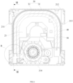
- the filter net 30 includes two filter subnets 31 that are spliced in a circumferential direction of the machine body 20.
- One of the filter subnets 31 covers the air inlet 201 on the first side wall 211 and a part of the air inlet 201 an the second side wall 212.
- the other of the filter 31 covers the other part of the air inlet 201 on the second side wall 212 and the air inlet 201 on the third side wall 213.
- Each of the first side wall 211 and the third side wall 213 is provided with a filter net mounting port 203 for the two filter subnets 31 to be mounted.
- the two filter subnets 31 each have their own mounting and dismounting ports, and each of the filter subnets 31 only needs to pass through one corner during the mounting process, that is, each of the filter subnets 31 only needs to be bent once.
- the mounting of the filter subnets 31 is more convenient.
- the filter subnets 31 need to have certain flexibility, so that they can bend themselves and be suitable for loading during sliding along the filter slot for insertion.
- each of the filter subnets 31 also needs to have some rigidity in order to be pushed into the filter slot as a whole.
- each of the filter subnets 31 may be configured as a plastic filter net.
- each of the filter subnets 31 can include a plastic frame and a flexible filter net configured on the plastic frame.
- the two filter subnets 31 are spliced in the middle of the second side wall 212, that is, the two filter subnets 31 are equal in length, so that the two filter subnets 31 can have same specifications and facilitate preparation.
- the side wall 21 also includes a fourth side wall 214 opposite to the second side wall 212.
- the fourth side wall 214 is generally disposed against a wall.
- the two filter net mounting ports 203 are respectively defined on the first side wall 211 and the third side wall 213, so that the filter subnets 31 can be assembled and disassembled without moving the dehumidifier, and the user can use the dehumidifier more conveniently.
- the present design is not limited to this.
- the two filter net mounting ports 203 may be defined on the fourth side wall 214 to hide the filter net mounting ports 203 in a position invisible to the user.
- each of the first side wall 211 and the third side wall 213 is configured with an inclined transition channel communicating the filter net mounting port 203 and the filter net slot.
- each of the filter subnets 31 is configured with a blocking member 311, and the other end of the filter subnet 31 is inserted into the filter slot from the filter net mounting port 203 until the blocking member 311 blocks the filter net mounting port 203. It can be understood that the filter net mounting port 203 is blocked by the blocking member 311, so that particulate matters such as dusts can be prevented from entering the dehumidifier through the filter net mounting port 203.
- the blocking member 311 is provided with a clasp 312 configured in a recessed manner.
- the filter subnet 31 can be easily pulled out, and at the same time, the clasp 312 is recessed, so that it avoids the situation that the clasp 312 prevents the machine body 20 from being accommodated in the water tank 10.
- the blocking member 311 may also be configured with a convex handle, as such, an avoidance notch is needed to be configured in the mounting port of the water tank 10, or the handle is needed to be provided at an upper position, and when the dehumidifier is in the idle state, the handle is exposed outside the water tank 10.
- an anti-disengagement structure is configured between each filter subnet 31 and the machine body 20, so that each filter subnet 31 can be positioned in the machine body 20 after being installed in the filter net slot, thereby preventing the filter subnet 31 from dropping out, and further improving assembly reliability of the filter subnet 31.
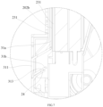
- the anti-disengagement structure includes a buckle hole 313 provided on the filter subnet 31, and a buckle 24 provided on an inner side of the filter mounting port 203.
- the buckle 24 can be engaged to the buckle hole 313 to restrict the filter subnet 31 from leaving the filter net mounting port 203.
- the buckle hole 313 can be configured on the filter net of the filter subnet 31 or on the blocking member 311 thereof.
- the filter subnet 31 includes a subnet body 31a and a subnet flange 31b configured in parallel on the same side of the blocking member 311.
- the buckle hole 313 is defined on the subnet flange 31b.
- the anti-disengagement structure is configured as a clamping structure, so that mounting and disassembly of the filter subnet 31 relative to the filter net mounting port 203 can be realized without additional tools (such as a screwdriver).
- the present design is not limited to this, in other embodiments, the anti-disengagement structure may be configured as, but not limited to, a screw-locking structure or the like.
- the machine body 20 is configured with a protective baffle 25 opposite to the filter net mounting port 203 and spaced from the filter net mounting port 203. In this way, after the filter net 30 is pulled out, a user can be restricted by the protective baffle 25 from extending hands or other objects into the machine body 20 to touch an electronic control wiring, a pipeline of the evaporator 40 or the like in the machine body 20.
Landscapes
- Engineering & Computer Science (AREA)
- Chemical & Material Sciences (AREA)
- Combustion & Propulsion (AREA)
- Mechanical Engineering (AREA)
- General Engineering & Computer Science (AREA)
- Drying Of Gases (AREA)
Claims (10)
- Entfeuchter, umfassend:einen Wassertank (10) mit einer Montageöffnung, wobei die Montageöffnung nach oben gerichtet ist;einen Maschinenkörper (20), aufweisend einen Leerlaufzustand, in dem der Maschinenkörper (20) zumindest teilweise in dem Wassertank (10) durch die Montageöffnung aufgenommen ist, und wobei der Maschinenkörper (20) einen Arbeitszustand aufweist, in dem der Maschinenkörper (20) relativ zu dem Wassertank (10) durch die Montageöffnung erstreckt ist, wobei der Maschinenkörper (20) mit einem Lufteinlass (201) und einem Filternetzschlitz neben dem Lufteinlass (201) versehen ist; unddadurch gekennzeichnet, dassein Filternetz (30) so in den Filternetzschlitz eingesetzt ist, dass das Filternetz (30) herausgezogen werden kann, und das Filternetz (30) den Lufteinlass (201) abdeckt,wobei der Maschinenkörper (20) eine Seitenwand (21) umfasst, der Lufteinlass (201) an der Seitenwand (21) vorgesehen ist; der Filternetzschlitz einen oberen Schlitz (202a) umfasst, um durch eine Oberseite des Filternetzes (30) eingesetzt zu werden, und einen unteren Schlitz (202b), um durch eine Unterseite des Filternetzes (30) eingesetzt zu werden, undwobei der Maschinenkörper (20) ferner eine obere Abdeckung (22), die mit einem oberen Ende der Seitenwand (21) verbunden ist, umfasst, und eine Wasseraufnahmeschale (23), die mit einem unteren Ende der Seitenwand (21) verbunden ist, der obere Schlitz (202a) an der oberen Abdeckung (22) vorgesehen ist, der untere Schlitz (202b) an der Wasseraufnahmeschale (23) vorgesehen ist.
- Entfeuchter gemäß Anspruch 1, wobei der Filternetzschlitz in dem Maschinenkörper (20) vorgesehen ist und die Seitenwand (21) mit einer Filternetz-Montageöffnung (203) versehen ist, wobei die Filternetz-Montageöffnung (203) zum Einsetzen des Filternetzes (30) dient.
- Entfeuchter gemäß Anspruch 1, wobei zwei parallele obere Führungsschienen (221) an der oberen Abdeckung (22) vorgesehen sind und in Abständen von dieser vorstehen, um den oberen Schlitz (202a) zwischen den beiden oberen Führungsschienen (221) auszubilden; und/oder,
zwei parallele untere Führungsschienen (231) an der Wasseraufnahmeschale (23) vorgesehen sind und in Abständen von dieser vorstehen, um den unteren Schlitz (202b) zwischen den beiden unteren Führungsschienen (231) auszubilden. - Entfeuchter gemäß einem der Ansprüche 1 bis 3, wobei die Seitenwand (21) eine erste Seitenwand (211), eine zweite Seitenwand (212) und eine dritte Seitenwand (213) umfasst, wobei die erste Seitenwand (211), die zweite Seitenwand (212) und die dritte Seitenwand (213) nacheinander verbunden sind, die erste Seitenwand (211) der dritten Seitenwand (213) gegenüberliegt und jede der ersten Seitenwand (211), der zweiten Seitenwand (212) und der dritten Seitenwand (213) mit einem Lufteinlass (201) versehen ist.
- Entfeuchter gemäß Anspruch 4, wobei das Filternetz (30) zwei Filterteilnetze (31) umfasst, wobei die zwei Filterteilnetze in einer Umfangsrichtung des Maschinenkörpers (20) miteinander gespleißt sind, eines der Filterteilnetze (31) den Lufteinlass (201) an der ersten Seitenwand (211) und einen Bereich des Lufteinlasses (201) an der zweiten Seitenwand (212) abdeckt, das andere Filterteilnetz (31) einen anderen Bereich des Lufteinlasses (201) an der zweiten Seitenwand (212) und den Lufteinlass (201) an der dritten Seitenwand (213) abdeckt;
jede der ersten Seitenwand (211) und der dritten Seitenwand (213) mit einer Filternetz-Montageöffnung (203) für die zwei Filterteilnetze (31) versehen ist, um jeweils darin montiert zu werden. - Entfeuchter gemäß Anspruch 5, wobei ein Ende des Filterteilnetzes (31) mit einem Sperrelement (311) versehen ist und ein anderes Ende des Filterteilnetzes (31) von der Filternetz-Montageöffnung (203) aus in den Filternetzschlitz eingeführt wird, bis das Sperrelement (311) die Filternetz-Montageöffnung (203) blockiert.
- Entfeuchter gemäß Anspruch 6, wobei das Sperrelement (311) mit einer Klammer (312) versehen ist, wobei die Klammer (312) vertieft ausgebildet ist.
- Entfeuchter gemäß einem der Ansprüche 5 bis 7, wobei zwischen dem Filterteilnetz (31) und dem Maschinenkörper (20) eine Entkopplungsschutzstruktur vorgesehen ist.
- Entfeuchter gemäß Anspruch 8, wobei die Entkopplungsschutzstruktur ein Knickloch (313), das an dem Filterteilnetz (31) vorgesehen ist, und eine Schnalle (24), die an einer Innenseite der Filternetz-Montageöffnung (203) vorgesehen ist, umfasst, wobei die Schnalle (24) geeignet ist, in dem Knickloch (313) geknickt zu werden, um das Filterteilnetz (31) daran zu hindern, sich von der Filternetz-Montageöffnung (203) zu entkoppeln.
- Entfeuchter gemäß einem der Ansprüche 2 bis 9, wobei der Maschinenkörper (20) mit einem Schutzblech (25) versehen ist, wobei das Schutzblech (25) von der Filternetz-Montageöffnung (203) beabstandet ist und der Filternetz-Montageöffnung (203) gegenüberliegt.
Applications Claiming Priority (3)
| Application Number | Priority Date | Filing Date | Title |
|---|---|---|---|
| CN202010126360.1A CN111156618B (zh) | 2020-02-27 | 2020-02-27 | 除湿机 |
| CN202020222372.XU CN211650554U (zh) | 2020-02-27 | 2020-02-27 | 除湿机 |
| PCT/CN2020/084377 WO2021169002A1 (zh) | 2020-02-27 | 2020-04-13 | 除湿机 |
Publications (4)
| Publication Number | Publication Date |
|---|---|
| EP3901529A1 EP3901529A1 (de) | 2021-10-27 |
| EP3901529A4 EP3901529A4 (de) | 2022-11-02 |
| EP3901529B1 true EP3901529B1 (de) | 2025-05-28 |
| EP3901529C0 EP3901529C0 (de) | 2025-05-28 |
Family
ID=77489816
Family Applications (1)
| Application Number | Title | Priority Date | Filing Date |
|---|---|---|---|
| EP20888725.7A Active EP3901529B1 (de) | 2020-02-27 | 2020-04-13 | Entfeuchter |
Country Status (2)
| Country | Link |
|---|---|
| EP (1) | EP3901529B1 (de) |
| WO (1) | WO2021169002A1 (de) |
Families Citing this family (1)
| Publication number | Priority date | Publication date | Assignee | Title |
|---|---|---|---|---|
| CN114602296A (zh) * | 2022-03-11 | 2022-06-10 | 国网河北省电力有限公司邯郸供电分公司 | 一种除湿装置 |
Family Cites Families (11)
| Publication number | Priority date | Publication date | Assignee | Title |
|---|---|---|---|---|
| JPS59183228A (ja) * | 1983-03-31 | 1984-10-18 | Matsushita Electric Ind Co Ltd | 空気調和機のエアフイルタ装置 |
| ES2319478B1 (es) * | 2006-05-12 | 2010-01-25 | Bsh Electrodomesticos España, S.A. | Aparato para la limpieza y la climatizacion de aire. |
| CN201242224Y (zh) * | 2008-06-13 | 2009-05-20 | 海信科龙电器股份有限公司 | 一种带有可抽拉式过滤网结构的空调器 |
| CN203595184U (zh) * | 2013-11-08 | 2014-05-14 | Tcl空调器(中山)有限公司 | 空调室内机和空调器 |
| CN206055925U (zh) * | 2016-09-26 | 2017-03-29 | 珠海格力电器股份有限公司 | 空气调节设备 |
| CN106288306A (zh) * | 2016-09-26 | 2017-01-04 | 珠海格力电器股份有限公司 | 空气调节设备 |
| CN107449059A (zh) * | 2017-07-19 | 2017-12-08 | 广东美的制冷设备有限公司 | 净化除湿机 |
| CN108413597A (zh) * | 2018-05-11 | 2018-08-17 | 广东美的制冷设备有限公司 | 壳体组件以及除湿机 |
| CN110748989A (zh) * | 2019-11-29 | 2020-02-04 | 广东美的制冷设备有限公司 | 除湿机 |
| CN110748987A (zh) * | 2019-11-29 | 2020-02-04 | 广东美的制冷设备有限公司 | 除湿机 |
| CN110748988A (zh) * | 2019-11-29 | 2020-02-04 | 广东美的制冷设备有限公司 | 除湿机 |
-
2020
- 2020-04-13 EP EP20888725.7A patent/EP3901529B1/de active Active
- 2020-04-13 WO PCT/CN2020/084377 patent/WO2021169002A1/zh not_active Ceased
Also Published As
| Publication number | Publication date |
|---|---|
| WO2021169002A1 (zh) | 2021-09-02 |
| EP3901529C0 (de) | 2025-05-28 |
| EP3901529A4 (de) | 2022-11-02 |
| EP3901529A1 (de) | 2021-10-27 |
Similar Documents
| Publication | Publication Date | Title |
|---|---|---|
| US11098906B2 (en) | Combined appliance and a kitchen device with the combined appliance | |
| US6643123B2 (en) | Switchgear cabinet with at least one cabinet door and a fan-assisted air circulation on an interior | |
| EP3130864A1 (de) | Innenraumeinheit einer klimaanlage | |
| US20050284113A1 (en) | Refrigerator having air-cleaner | |
| EP3081871A1 (de) | Entfeuchter | |
| CN212619197U (zh) | 机身和除湿机 | |
| CN111156618B (zh) | 除湿机 | |
| EP3901529B1 (de) | Entfeuchter | |
| US12053730B2 (en) | Dehumidifier | |
| CN211650554U (zh) | 除湿机 | |
| EP2181292A2 (de) | Klimaanlage | |
| US20250185878A1 (en) | Shoe care apparatus | |
| US20030217834A1 (en) | Flexible room air conditioner | |
| JP5505321B2 (ja) | 空気調和機 | |
| KR100811657B1 (ko) | 공기조화기 | |
| CN203824022U (zh) | 空调机室内机 | |
| CN215765612U (zh) | 空气净化装置 | |
| KR20090001867U (ko) | 공기조화기 | |
| JPH11101498A (ja) | 空気調和機のエアフィルタ取付構造 | |
| KR100761952B1 (ko) | 제습기 | |
| ITTO20000776A1 (it) | Ventilatore filtrante. | |
| KR100234036B1 (ko) | 공조기의 필터 장착구조 | |
| CN109269103A (zh) | 热风机及换热系统 | |
| JP2004352068A (ja) | 空気調和機 | |
| JP6707815B2 (ja) | ショーケース |
Legal Events
| Date | Code | Title | Description |
|---|---|---|---|
| STAA | Information on the status of an ep patent application or granted ep patent |
Free format text: STATUS: UNKNOWN |
|
| STAA | Information on the status of an ep patent application or granted ep patent |
Free format text: STATUS: THE INTERNATIONAL PUBLICATION HAS BEEN MADE |
|
| PUAI | Public reference made under article 153(3) epc to a published international application that has entered the european phase |
Free format text: ORIGINAL CODE: 0009012 |
|
| STAA | Information on the status of an ep patent application or granted ep patent |
Free format text: STATUS: REQUEST FOR EXAMINATION WAS MADE |
|
| 17P | Request for examination filed |
Effective date: 20210525 |
|
| AK | Designated contracting states |
Kind code of ref document: A1 Designated state(s): AL AT BE BG CH CY CZ DE DK EE ES FI FR GB GR HR HU IE IS IT LI LT LU LV MC MK MT NL NO PL PT RO RS SE SI SK SM TR |
|
| A4 | Supplementary search report drawn up and despatched |
Effective date: 20221004 |
|
| RIC1 | Information provided on ipc code assigned before grant |
Ipc: F24F 1/035 20190101ALI20220927BHEP Ipc: F24F 1/0358 20190101ALI20220927BHEP Ipc: F24F 13/28 20060101ALI20220927BHEP Ipc: F24F 13/22 20060101ALI20220927BHEP Ipc: F24F 13/20 20060101ALI20220927BHEP Ipc: F24F 3/14 20060101AFI20220927BHEP |
|
| DAV | Request for validation of the european patent (deleted) | ||
| DAX | Request for extension of the european patent (deleted) | ||
| GRAP | Despatch of communication of intention to grant a patent |
Free format text: ORIGINAL CODE: EPIDOSNIGR1 |
|
| STAA | Information on the status of an ep patent application or granted ep patent |
Free format text: STATUS: GRANT OF PATENT IS INTENDED |
|
| INTG | Intention to grant announced |
Effective date: 20250129 |
|
| GRAS | Grant fee paid |
Free format text: ORIGINAL CODE: EPIDOSNIGR3 |
|
| GRAA | (expected) grant |
Free format text: ORIGINAL CODE: 0009210 |
|
| STAA | Information on the status of an ep patent application or granted ep patent |
Free format text: STATUS: THE PATENT HAS BEEN GRANTED |
|
| AK | Designated contracting states |
Kind code of ref document: B1 Designated state(s): AL AT BE BG CH CY CZ DE DK EE ES FI FR GB GR HR HU IE IS IT LI LT LU LV MC MK MT NL NO PL PT RO RS SE SI SK SM TR |
|
| REG | Reference to a national code |
Ref country code: GB Ref legal event code: FG4D |
|
| REG | Reference to a national code |
Ref country code: CH Ref legal event code: EP |
|
| REG | Reference to a national code |
Ref country code: IE Ref legal event code: FG4D Ref country code: DE Ref legal event code: R096 Ref document number: 602020052109 Country of ref document: DE |
|
| U01 | Request for unitary effect filed |
Effective date: 20250620 |
|
| U07 | Unitary effect registered |
Designated state(s): AT BE BG DE DK EE FI FR IT LT LU LV MT NL PT RO SE SI Effective date: 20250707 |
|
| PG25 | Lapsed in a contracting state [announced via postgrant information from national office to epo] |
Ref country code: ES Free format text: LAPSE BECAUSE OF FAILURE TO SUBMIT A TRANSLATION OF THE DESCRIPTION OR TO PAY THE FEE WITHIN THE PRESCRIBED TIME-LIMIT Effective date: 20250528 |
|
| PG25 | Lapsed in a contracting state [announced via postgrant information from national office to epo] |
Ref country code: NO Free format text: LAPSE BECAUSE OF FAILURE TO SUBMIT A TRANSLATION OF THE DESCRIPTION OR TO PAY THE FEE WITHIN THE PRESCRIBED TIME-LIMIT Effective date: 20250828 Ref country code: GR Free format text: LAPSE BECAUSE OF FAILURE TO SUBMIT A TRANSLATION OF THE DESCRIPTION OR TO PAY THE FEE WITHIN THE PRESCRIBED TIME-LIMIT Effective date: 20250829 |
|
| PG25 | Lapsed in a contracting state [announced via postgrant information from national office to epo] |
Ref country code: PL Free format text: LAPSE BECAUSE OF FAILURE TO SUBMIT A TRANSLATION OF THE DESCRIPTION OR TO PAY THE FEE WITHIN THE PRESCRIBED TIME-LIMIT Effective date: 20250528 |
|
| PG25 | Lapsed in a contracting state [announced via postgrant information from national office to epo] |
Ref country code: HR Free format text: LAPSE BECAUSE OF FAILURE TO SUBMIT A TRANSLATION OF THE DESCRIPTION OR TO PAY THE FEE WITHIN THE PRESCRIBED TIME-LIMIT Effective date: 20250528 |
|
| PG25 | Lapsed in a contracting state [announced via postgrant information from national office to epo] |
Ref country code: RS Free format text: LAPSE BECAUSE OF FAILURE TO SUBMIT A TRANSLATION OF THE DESCRIPTION OR TO PAY THE FEE WITHIN THE PRESCRIBED TIME-LIMIT Effective date: 20250828 |
|
| PG25 | Lapsed in a contracting state [announced via postgrant information from national office to epo] |
Ref country code: IS Free format text: LAPSE BECAUSE OF FAILURE TO SUBMIT A TRANSLATION OF THE DESCRIPTION OR TO PAY THE FEE WITHIN THE PRESCRIBED TIME-LIMIT Effective date: 20250928 |
|
| PG25 | Lapsed in a contracting state [announced via postgrant information from national office to epo] |
Ref country code: SM Free format text: LAPSE BECAUSE OF FAILURE TO SUBMIT A TRANSLATION OF THE DESCRIPTION OR TO PAY THE FEE WITHIN THE PRESCRIBED TIME-LIMIT Effective date: 20250528 |
|
| PG25 | Lapsed in a contracting state [announced via postgrant information from national office to epo] |
Ref country code: CZ Free format text: LAPSE BECAUSE OF FAILURE TO SUBMIT A TRANSLATION OF THE DESCRIPTION OR TO PAY THE FEE WITHIN THE PRESCRIBED TIME-LIMIT Effective date: 20250528 |
|
| PG25 | Lapsed in a contracting state [announced via postgrant information from national office to epo] |
Ref country code: SK Free format text: LAPSE BECAUSE OF FAILURE TO SUBMIT A TRANSLATION OF THE DESCRIPTION OR TO PAY THE FEE WITHIN THE PRESCRIBED TIME-LIMIT Effective date: 20250528 |
|
| PLBE | No opposition filed within time limit |
Free format text: ORIGINAL CODE: 0009261 |
|
| STAA | Information on the status of an ep patent application or granted ep patent |
Free format text: STATUS: NO OPPOSITION FILED WITHIN TIME LIMIT |
|
| REG | Reference to a national code |
Ref country code: CH Ref legal event code: L10 Free format text: ST27 STATUS EVENT CODE: U-0-0-L10-L00 (AS PROVIDED BY THE NATIONAL OFFICE) Effective date: 20260409 |