EP3901582A1 - Dispositif inductif de mesure d'angle - Google Patents
Dispositif inductif de mesure d'angle Download PDFInfo
- Publication number
- EP3901582A1 EP3901582A1 EP21153915.0A EP21153915A EP3901582A1 EP 3901582 A1 EP3901582 A1 EP 3901582A1 EP 21153915 A EP21153915 A EP 21153915A EP 3901582 A1 EP3901582 A1 EP 3901582A1
- Authority
- EP
- European Patent Office
- Prior art keywords
- conductor track
- track section
- conductor
- section
- distance
- Prior art date
- Legal status (The legal status is an assumption and is not a legal conclusion. Google has not performed a legal analysis and makes no representation as to the accuracy of the status listed.)
- Granted
Links
Images

Classifications
-
- G—PHYSICS
- G01—MEASURING; TESTING
- G01D—MEASURING NOT SPECIALLY ADAPTED FOR A SPECIFIC VARIABLE; ARRANGEMENTS FOR MEASURING TWO OR MORE VARIABLES NOT COVERED IN A SINGLE OTHER SUBCLASS; TARIFF METERING APPARATUS; MEASURING OR TESTING NOT OTHERWISE PROVIDED FOR
- G01D5/00—Mechanical means for transferring the output of a sensing member; Means for converting the output of a sensing member to another variable where the form or nature of the sensing member does not constrain the means for converting; Transducers not specially adapted for a specific variable
- G01D5/12—Mechanical means for transferring the output of a sensing member; Means for converting the output of a sensing member to another variable where the form or nature of the sensing member does not constrain the means for converting; Transducers not specially adapted for a specific variable using electric or magnetic means
- G01D5/14—Mechanical means for transferring the output of a sensing member; Means for converting the output of a sensing member to another variable where the form or nature of the sensing member does not constrain the means for converting; Transducers not specially adapted for a specific variable using electric or magnetic means influencing the magnitude of a current or voltage
- G01D5/20—Mechanical means for transferring the output of a sensing member; Means for converting the output of a sensing member to another variable where the form or nature of the sensing member does not constrain the means for converting; Transducers not specially adapted for a specific variable using electric or magnetic means influencing the magnitude of a current or voltage by varying inductance, e.g. by a movable armature
- G01D5/204—Mechanical means for transferring the output of a sensing member; Means for converting the output of a sensing member to another variable where the form or nature of the sensing member does not constrain the means for converting; Transducers not specially adapted for a specific variable using electric or magnetic means influencing the magnitude of a current or voltage by varying inductance, e.g. by a movable armature by influencing the mutual induction between two or more coils
- G01D5/2053—Mechanical means for transferring the output of a sensing member; Means for converting the output of a sensing member to another variable where the form or nature of the sensing member does not constrain the means for converting; Transducers not specially adapted for a specific variable using electric or magnetic means influencing the magnitude of a current or voltage by varying inductance, e.g. by a movable armature by influencing the mutual induction between two or more coils by a movable non-ferromagnetic conductive element
- G01D5/206—Mechanical means for transferring the output of a sensing member; Means for converting the output of a sensing member to another variable where the form or nature of the sensing member does not constrain the means for converting; Transducers not specially adapted for a specific variable using electric or magnetic means influencing the magnitude of a current or voltage by varying inductance, e.g. by a movable armature by influencing the mutual induction between two or more coils by a movable non-ferromagnetic conductive element constituting a short-circuiting element
Definitions
- the invention relates to an inductive angle measuring device for determining relative angular positions according to claim 1.
- Inductive angle measuring devices are used, for example, as angle measuring devices for determining the angular position of two machine parts that can be rotated relative to one another.
- excitation tracks and receiver tracks for example in the form of conductor tracks, are often applied to a common, usually multilayer, printed circuit board that is firmly connected, for example, to a stator of an angle measuring device.
- this circuit board is a scale element on which graduation structures are applied and which is connected to the rotor of the angle encoder in a rotationally fixed manner. If an electrical excitation current that changes over time is applied to the excitation coils, signals that are dependent on the angular position are generated in the receiver coils during the relative rotation between the rotor and the stator. These signals are then processed further in evaluation electronics.
- Such inductive angle measuring devices are often used as measuring devices for electrical drives to determine the relative movement or the relative position of corresponding machine parts.
- the angular position values generated are used by subsequent electronics Control of the drives is supplied via a corresponding interface arrangement.
- an inductive angle sensor which has a short-circuit line on the rotor element which can be scanned by receiving coils which have comparatively long straight sections.
- the invention is based on the object of creating an inductive angle measuring device by means of which a precise determination of a relative angular position is made possible by filtering out harmonics from signals received from receiver conductor tracks.
- the inductive angle measuring device has a scanning element and a scale element.
- the scale element comprises a graduation track running around an axis, the graduation track having several conductor track groups which are electrically connected and are arranged in a row in the measuring direction so that adjacent conductor track groups have a center-to-center spacing in the measuring direction.
- the conductor track groups each have a first conductor track section, a second conductor track section, a third conductor track section and a fourth conductor track section. These four conductor track sections extend transversely to the measuring direction, that is to say with a directional component orthogonal to the direction of measurement.
- the direction of measurement often corresponds to the circumferential direction in relation to the axis or around the axis.
- the first conductor track section and the second conductor track section are electrically connected to one another.
- the third conductor track section and the fourth conductor track section are also electrically connected to one another.
- the first conductor track section is arranged offset with respect to the third conductor track section at a distance in the measuring direction.
- the fourth conductor track section is arranged offset with respect to the second conductor track section at the (same) distance.
- the distance is dimensioned in such a way that it corresponds to the center-to-center distance divided by a natural number M greater than or equal to 4.
- the scanning element has an excitation track and a receiver track with at least two receiver conductor tracks, the receiver conductor tracks having a sinusoidal circumferential, spatially periodic course with a period length which corresponds to the center-to-center distance.
- signals can be generated by the receiver conductor tracks which have practically no disruptive harmonic components, the sinusoidal receiver conductor tracks not having any straight sections.
- the scanning element and the scale element are usually arranged opposite one another and are spaced apart from one another by an air gap which extends in the axial or radial direction.
- the receiver conductor tracks are often arranged in such a way that they have a phase offset (e.g. a phase offset of 90 °) to one another.
- the inductive angle measuring device is advantageously configured in such a way that the scanning element has two excitation tracks which each comprise at least one conductor track, the excitation tracks running in the measuring direction or along the measuring direction.
- the receiver track is arranged between the excitation tracks.
- the angle measuring device also includes an electronic circuit through which in the excitation tracks an electrical excitation current can be generated. At a specific point in time, the excitation current advantageously runs in the same direction in the at least two excitation tracks.
- the natural number M is greater than or equal to 6.
- center-to-center distances and distances between conductor track sections are specified in terms of angles, i.e. either in degrees or fractions of a full angle or in radians.
- a conductor track group is to be understood in particular as an area on the scale element in which congruent courses of the conductor track sections, in particular of the entire conductor tracks, are present over a section in the measuring direction with an extent that corresponds to the center-to-center distance TP, if the section in question is around the angular center-to-center distance TP or an integral multiple thereof is rotated.
- the scale element thus has sections, namely the conductor track groups, which are arranged in a periodically recurring manner with the period which corresponds to the center-to-center distance TP.
- the conductor track groups are electrically connected to one another in series, so that an electrically closed dividing track is present; in particular, the conductor track groups can be partial areas of conductor tracks which are in particular designed to be endless.
- the conductor track groups can be designed in such a way that the course of the conductor track sections located therein is axially symmetrical with respect to a radially extending axis of symmetry.
- the scale element is advantageously designed in such a way that the four conductor track sections each extend in a direction with a radial directional component in relation to the axis.
- the distance, based on the measurement direction, between two not directly adjacent conductor track sections within a conductor track group corresponds to half the center-to-center distance.
- the first conductor track section is arranged offset in the measuring direction with respect to the fourth conductor track section at a distance that corresponds to half the center-to-center distance.
- the third conductor track section is arranged offset with respect to the second conductor track section at a distance which corresponds to half the center-to-center distance.
- the first conductor track section and the second conductor track section as well as a first connection conductor track section and a second connection conductor track section are advantageously sections of a first conductor track. Furthermore, the first conductor track section and the second conductor track section are electrically connected to one another in series by the first connection conductor track section and the second connection conductor track section.
- the third conductor track section and the fourth conductor track section as well as a third connection conductor track section and a fourth connection conductor track section are sections of a second conductor track, the third conductor track section and the fourth conductor track section being electrically connected to one another in series by the third connection conductor track section and the fourth connection conductor track section.
- the connecting conductor track sections advantageously extend in one direction with a directional component parallel to the measuring direction.
- the four conductor track sections are advantageously arranged on a flat plane.
- the connecting conductor track sections are arranged alternately radially on the inside and radially on the outside in the measuring direction with respect to the conductor track sections.
- the conductor track sections can also be arranged on a circumferential surface, for example a jacket surface of a cylindrical body.
- the four conductor track sections extend in one direction with an axial directional component (based on the (rotational) axis).
- the scale element has a curved surface on which the graduation track is arranged.
- the conductor track groups can then be designed in such a way that the course of the conductor track sections located therein is axially symmetrical with respect to an axis of symmetry running parallel to the (rotational) axis.
- the four conductor track sections have a width in the measuring direction of less than 300 ⁇ m, in particular of less than 200 ⁇ m or of less than 150 ⁇ m.
- the conductor track groups each have, in addition to the four conductor track sections, a fifth conductor track section, a sixth conductor track section, a seventh conductor track section and an eighth conductor track section.
- the fifth conductor track section and the sixth conductor track section are electrically connected to one another.
- the seventh conductor track section and the eighth conductor track section are also electrically connected to one another.
- the first conductor track section is offset from the fifth conductor track section at a distance in the measuring direction and the third conductor track section is offset from the seventh conductor track section at a distance in the measuring direction.
- the respective distance corresponds to the center-to-center distance divided by a natural number M greater than or equal to 6.
- the distance between the first conductor track section and the fifth conductor track section is advantageously the same as the distance between the third conductor track section and the seventh conductor track section.
- the at least two receiver conductor tracks are arranged on a flat plane, in particular the plane of the at least two receiver conductor tracks being arranged axially offset to the plane of the four conductor track sections.
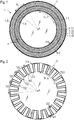
- the invention is described on the basis of an angle measuring device which is used to detect an angular position ⁇ between a scanning element 1 ( Figure 1 ) and a scale element 2 ( Figure 2 ) or a scale is determined, the axis A in the figures being oriented orthogonally to the respective plane of the drawing.
- the circumferential direction can thus be defined as a measuring direction U.
- the scanning element 1 is designed as a printed circuit board, which has several layers, and is used for scanning the scale element 2.
- the in the Figure 1 The scanning element 1 shown has four receiver conductor tracks 1.11, 1.12, 1.13, 1.14, which are arranged in a receiver track 1.1, as well as exciter tracks 1.3, 1.4.
- the receiver conductor tracks 1.11, 1.12, 1.13, 1.14 are arranged radially between the excitation tracks 1.3, 1.4.
- the receiver conductor tracks 1.11, 1.12, 1.13, 1.14 run on different levels with plated-through holes, so that undesired short circuits are avoided at crossing points.
- at least two layers are provided in the circuit board structure.
- the receiver conductor tracks 1.11, 1.12, 1.13, 1.14 have a spatially periodic course that is essentially sinusoidal or sinusoidal.
- the abscissa x (indicated by the arrow) runs on the receiver conductor tracks 1.11, 1.12, 1.13, 1.14 Figure 1 ) of the associated sine lines along a circular line around the axis A.
- each of the receiver conductor tracks 1.11, 1.12, 1.13, 1.14 runs through sixteen full sine periods (16 ⁇ 2 ⁇ or 16 ⁇ 360 °) or the circumferential abscissa x has a length of 16 * 2 ⁇ or 16 * 360 ° or 16 * PL.
- the receiver conductor tracks 1.11, 1.12, 1.13, 1.14 are offset relative to one another along the measurement direction U.
- adjacent receiver conductor tracks 1.11, 1.12, 1.13, 1.14 are offset from one another by 1/8 of the full sine period (by ⁇ / 4 or 45 ° with respect to the abscissa x).
- the receiver conductor tracks 1.11, 1.12, 1.13, 1.14 are electrically connected in such a way that they can ultimately deliver signals that are phase-shifted by 90 °.
- the receiver conductor tracks 1.11, 1.12, 1.13, 1.14 each have sixteen periods along the circular line, so that each of the receiver conductor tracks 1.11, 1.12, 1.13, 1.14 has a period length PL of 22.5 °.
- length sizes in the circumferential or measuring direction U are indicated by angular dimensions.
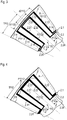
- the scale element 2 is shown in a top view.
- the scale element 2 consists of a substrate which, in the exemplary embodiment shown, is made of epoxy resin and on which a first conductor track 2.1 and a second conductor track 2.2 are arranged in a graduation track TS1.
- copper was applied to the substrate as the material for the first conductor track 2.1 and the second conductor track 2.2.
- the conductor track 2.1 and the second conductor track 2.2 each have a width of 150 ⁇ m.
- the graduation track TS1 is arranged centrally with respect to the axis A and circumferentially around the axis A in the measuring direction U.
- the first conductor track 2.1 and the second conductor track 2.2 have a meandering course and are endless.
- the division track TS1 can (or the associated first conductor track 2.1 and second conductor track 2.2 can) be subdivided into what are known as conductor track groups TG.
- the graduation track TS1 comprises a total of sixteen conductor track groups TG, the center-to-center spacing TP of which is 22.5 ° (360 ° / 16) or 0.39 (2 ⁇ / 16) radians.
- Conductor track groups TG are sections on the graduation track TS1 which extend over an angular distance corresponding to the center-to-center distance TP. In adjacent conductor track groups TG, the courses of the first conductor track 2.1 and the second conductor track 2.2 are congruent when one of the Conductor groups TG is rotated about the axis A with an amount corresponding to the center-to-center distance TP.
- a conductor track group TG extends in the circumferential direction between the radial lines R, the distance between which is also 22.5 ° (2 ⁇ TP / 2).
- such conductor track groups TG have a first conductor track section 2.11, a second conductor track section 2.12, a third conductor track section 2.21 and a fourth conductor track section 2.22, the four conductor track sections 2.11, 2.12; 2.21, 2.22 extend transversely to the measuring direction U, that is, in relation to the axis A in the radial direction and each have a width of 150 ⁇ m.
- the conductor track sections 2.11, 2.12; 2.21, 2.22 shown slightly conical with respect to their width with decreasing width towards the axis A.
- the width of 150 ⁇ m relates to the maximum width of the conductor track sections 2.11, 2.12; 2.21, 2.22.
- the four conductor track sections 2.11, 2.12; 2.21, 2.22 can be assigned to two pairs of conductor track sections P1112, P2122.
- the first conductor track 2.1 thus has two radial conductor track sections 2.11, 2.12, namely the first conductor track section 2.11 and the second conductor track section 2.12, which are assigned to the conductor track section pair P1112.
- the second conductor track 2.2 has two radial conductor track sections 2.21, 2.22 (here the third conductor track section 2.21 and the fourth conductor track section 2.22), which are assigned to the conductor track section pair P2122. Furthermore, the first conductor track 2.1 and the second conductor track 2.2 have connecting conductor track sections 2.13, 2.14, 2.23, 2.24 which, in the exemplary embodiment presented, run in the circumferential or measuring direction U and electrically connect the radial conductor track sections 2.21, 2.22 within a pair of conductor track sections P1112, P2122.
- the first conductor track 2.1 comprises a first connection conductor track section 2.13 and a second connection conductor track section 2.14, so that the first conductor track section 2.11 and the second conductor track section 2.12 are electrically connected to one another in series by the first and second connection conductor track sections 2.13, 2.14.
- the second conductor track also includes 2.2 a third connecting conductor track section 2.23 and a fourth connecting conductor track section 2.24.
- the third interconnect section 2.21 and the fourth interconnect section 2.22 are electrically connected to one another in series through the third connecting interconnect section 2.23 and the fourth interconnecting interconnect section 2.24.
- the graduation track TS1 thus consists of a periodic sequence of electrically conductive conductor track sections 2.11, 2.12; 2.21, 2.22 between which non-conductive dividing areas are arranged.
- the conductor track sections 2.11, 2.12; 2.21, 2.22, which belong to one and the same conductor track 2.1, 2.2, are electrically connected to one another in series.
- Those radial conductor track sections 2.11, 2.12; 2.21, 2.22, which belong to different pairs of conductor track sections P1112, P2122, are each arranged offset in the circumferential direction at a distance d12. Accordingly, the two immediately adjacent two radial conductor track sections 2.11, 2.12 of the first conductor track 2.1 are arranged offset at a distance d12 in the circumferential direction from the two radial conductor track sections 2.21, 2.22 of the second conductor track 2.2.
- the first conductor track section 2.11 with respect to the third conductor track section 2.21 and the fourth conductor track section 2.22 with respect to the second conductor track section 2.12 are each offset by a distance d12 in the measuring direction U.
- the first conductor track section 2.11 of the first conductor track 2.1 is offset by a distance d1122 in the measuring direction U from the fourth conductor track section 2.22, which is not arranged directly adjacent to the first conductor track section 2.11 and belongs to the second conductor track 2.2.
- the conductor track sections 2.11, 2.12; 2.21, 2.22 arranged axially symmetrically with respect to the central, radially extending axis of symmetry.
- the connecting conductor track sections 2.13, 2.14, 2.23, 2.24 are likewise arranged axially symmetrically between the radial lines R.
- the scanning element 1 and the scale element 2 face each other axially, so that the axis A runs through the center points of both elements and in the case of a relative rotation between the scale element 2 and the scanning element 1 in the receiver conductor tracks 1.11, 1.12, 1.13, 1.14 a from the respective angular position dependent signal can be generated by induction effects.
- the prerequisite for the formation of corresponding signals is that the excitation tracks 1.3, 1.4 generate a time-changing electromagnetic excitation field in the area of the scanned graduation track TS1.
- the excitation tracks 1.3, 1.4 are designed as a plurality of planar-parallel, current-carrying individual conductor tracks.
- the scanning element 1 has an electronic circuit which comprises, for example, an ASIC module.
- This electronic circuit of the scanning element 1 works not only as an evaluation element, but also as an excitation control element, under whose control the excitation current, which then flows through the excitation tracks 1.3, 1.4 or through the individual conductor tracks, is generated. Both excitation tracks 1.3, 1.4 are thus energized by one and the same excitation control element.
- an excitation current flows through all of the excitation tracks 1.3, 1.4 in the same direction, then around the respective excitation track 1.3, 1.4 an electromagnetic tube-like or cylindrical shape is formed Field off.
- the field lines of the resulting electromagnetic field run in the form of concentric circles around the excitation tracks 1.3, 1.4, the direction of the field lines depending in a known manner on the direction of the current in the excitation tracks 1.3, 1.4.
- the current direction I13, I14 ( Figure 1 ) of the excitation tracks 1.3, 1.4 or the corresponding interconnection of the excitation tracks 1.3, 1.4 is to be selected in the same direction, so that the field lines in the area of the receiver track 1.1 are oriented in opposite directions.
- the current flow in the excitation tracks 1.3, 1.4 induces a current in the first conductor track 2.1 and in the second conductor track 2.2 of the scale element 2, the induced currents each having a current direction I21, I22 ( Figure 2 ) exhibit.
- the current direction I21 in the first conductor track 2.1 and the current direction I22 in the second conductor track 2.2 of the scale element 2 run parallel to one another (not in opposite directions or anti-parallel).
- the considerations in connection with the current directions I13, I14; I21, I22 only apply to one and the same point in time, since the excitation current is an alternating current.
- the first conductor track 2.1 and the second conductor track 2.2 run in a meander shape and nested in one another.
- the dimensioning of the distances d12, d1122, d2112 between the relevant conductor track sections 2.11, 2.12; 2.21, 2.22 in connection with the sinusoidal course of the receiver conductor tracks 1.11, 1.12, 1.13, 1.14 has the consequence that in the exemplary embodiment presented, the signals generated by the receiver conductor tracks 1.11, 1.12, 1.13, 1.14 have almost no third harmonics (harmonics) and practically no even-numbered ones Exhibit harmonics. This minimizes interpolation errors for determining the angular position values.
- FIG. 4 Another embodiment (second embodiment) of the invention is described. This differs from the first exemplary embodiment essentially in that instead of the connecting conductor track sections 2.13, 2.14, 2.23, 2.24 ( Figure 3 ) now one-piece connecting conductor track sections 2.23 ', 2.24' are provided, each with a parallel course, through which the entire induced current can flow.
- the graduation track TS1 can also comprise a third conductor track 2.3 and a fourth conductor track 2.4.
- the conductor track groups TG here additionally each have a fifth conductor track section 2.31, a sixth conductor track section 2.32, a seventh conductor track section 2.41 and an eighth conductor track section 2.42.
- the first conductor track section 2.11 is arranged offset with respect to the fifth conductor track section 2.31 at a distance d13 in the measurement direction U.
- the third conductor track section 2.21 is offset from the seventh conductor track section 2.41 at a distance d24 in the measuring direction U.
- conductor track sections 2.31, 2.32; 2.41, 2.42 can be assigned to two pairs of conductor track sections P3132, P4142.
- the third conductor track 2.3 has two radial conductor track sections 2.31, 2.32, which are assigned to the pair of conductor track sections P3132
- the fourth conductor track 2.4 has two radial conductor track sections 2.41, 2.42, which are assigned to the pair of conductor track sections P4142.
- the third conductor track 2.3 and the fourth conductor track 2.4 also have connecting conductor track sections 2.33, 2.34, 2.43, 2.44 which, in the exemplary embodiment presented, run in the circumferential direction and the radial conductor track sections 2.31, 2.32; 2.41, 2.42 electrically connect to one another within a pair of conductor track sections P3132, P4142.
- the graduation track TS1 consists of a periodic sequence of electrically conductive conductor track sections 2.11, 2.12; 2.21, 2.22; 2.31, 2.32; 2.41, 2.42 between which non-conductive dividing areas are arranged.
- d 12th TP / 6th
- two conductor track sections 2.11, 2.12; 2.21, 2.22; 2.31, 2.32; 2.41, 2.42 of a conductor track group TG each have a distance which corresponds to half the center-to-center distance TP.
- the fifth conductor track section 2.31 of the third conductor track 2.3 is offset by a distance TP / 2 in the measuring direction U from the fourth conductor track section 2.22, which is not arranged directly adjacent to the third conductor track section 2.31 and belongs to the second conductor track 2.2.
- All conductor tracks 2.1 to 2.4 run in a meander shape and are nested in one another.
- the third harmonic filtered from the signals generated by the receiver conductor tracks 1.11, 1.12, 1.13, 1.14, but also the fifth harmonic and all even-numbered harmonics.
- FIG. 6 an alternative embodiment of the scanning element 1 (fourth embodiment) is shown. Similar to the first exemplary embodiment, two conductor tracks 2.1, 2.2 are provided there, the first conductor track 2.1 and the second conductor track 2.2 not being designed as conductors that are electrically separated from one another, that is to say are not arranged electrically purely in parallel, but are connected in series.
- connecting conductor tracks 2.5, 2.6 are arranged on two levels or with the aid of a second copper layer of the printed circuit board of the scanning element 1.
- These connect the two conductor tracks 2.1, 2.2 with the help of micro vias in such a way that they are connected to one another in series.
- This arrangement has the particular advantage that it is prevented that different currents can flow in the conductor tracks 2.1, 2.2. Such an effect (currents of different sizes) could lead to limited harmonic filtering or filtering of the harmonics.
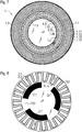
- a fifth embodiment is shown in Figures 7 and 8 shown.
- the scanning element 1 now also includes a further inner receiver track 1.2, which includes four receiver conductor tracks 1.21, 1.22, 1.23, 1.24.
- the receiver conductor tracks 1.21, 1.22, 1.23, 1.24 have a spatially periodic course that is essentially sinusoidal or sinusoidal, the abscissa of the sinus lines running along a circular line around the axis A.
- the receiver conductor tracks 1.21, 1.22, 1.23, 1.24 are arranged analogously to the first exemplary embodiment, that is to say offset by 45 ° relative to one another, so that they can deliver signals that are phase-shifted by 90 ° with appropriate electrical interconnection.
- the receiver conductor tracks 1.21, 1.22, 1.23, 1.24 of the inner receiver track 1.2 each have three periods along the circular line.
- the sensing element 1 comprises a further excitation track 1.5, which comprises a plurality of excitation lines or excitation conductor tracks.
- the current direction of the excitation track is 1.5 based on the current direction of the excitation tracks 1.3, 1.4 to be selected in opposite directions.
- the inner graduation track TS2 consists of graduation areas 2.7 in which electrically conductive material, here copper, is applied. No conductive material is arranged between the dividing areas 2.7.
- the receiver track 1.1 can be used to generate comparatively high-resolution angular position values for the relative angular position, while the further receiver track 1.2 can be used to generate comparatively coarse angular position values.
- the fine angular position values are connected to the comparatively coarse angular position values, so that the circuit generates a high-resolution absolute angular position value as a result.
Landscapes
- Physics & Mathematics (AREA)
- General Physics & Mathematics (AREA)
- Transmission And Conversion Of Sensor Element Output (AREA)
Applications Claiming Priority (1)
| Application Number | Priority Date | Filing Date | Title |
|---|---|---|---|
| DE102020205202.6A DE102020205202A1 (de) | 2020-04-23 | 2020-04-23 | Induktive Winkelmesseinrichtung |
Publications (2)
| Publication Number | Publication Date |
|---|---|
| EP3901582A1 true EP3901582A1 (fr) | 2021-10-27 |
| EP3901582B1 EP3901582B1 (fr) | 2023-05-17 |
Family
ID=74346907
Family Applications (1)
| Application Number | Title | Priority Date | Filing Date |
|---|---|---|---|
| EP21153915.0A Active EP3901582B1 (fr) | 2020-04-23 | 2021-01-28 | Dispositif inductif de mesure d'angle |
Country Status (3)
| Country | Link |
|---|---|
| EP (1) | EP3901582B1 (fr) |
| JP (1) | JP7620442B2 (fr) |
| DE (1) | DE102020205202A1 (fr) |
Cited By (1)
| Publication number | Priority date | Publication date | Assignee | Title |
|---|---|---|---|---|
| US12163811B2 (en) | 2022-08-26 | 2024-12-10 | Semiconductor Components Industries, Llc | Inductive angular position sensor |
Families Citing this family (2)
| Publication number | Priority date | Publication date | Assignee | Title |
|---|---|---|---|---|
| DE102022208799A1 (de) | 2022-08-25 | 2024-03-07 | Robert Bosch Gesellschaft mit beschränkter Haftung | Induktive Sensoranordnung zur Erfassung einer Drehbewegung |
| EP4484897B1 (fr) * | 2023-06-26 | 2025-08-06 | Dr. Johannes Heidenhain GmbH | Dispositif inductif de mesure d'angle |
Citations (6)
| Publication number | Priority date | Publication date | Assignee | Title |
|---|---|---|---|---|
| US5406155A (en) * | 1992-06-03 | 1995-04-11 | Trw Inc. | Method and apparatus for sensing relative position between two relatively rotatable members |
| EP0909955A2 (fr) | 1997-09-05 | 1999-04-21 | Hella KG Hueck & Co. | Détecteur angulaire inductif |
| DE69526770T2 (de) * | 1994-10-26 | 2003-02-06 | Trw Inc., Lyndhurst | Resolver für Reluktanzmotor für Lenkhilfe mit Ringen und sinusförmigen Leitern |
| EP1715298A2 (fr) * | 2005-04-19 | 2006-10-25 | Mitutoyo Corporation | Encodeur entièrement rotatif et micromètre |
| EP2329225B1 (fr) | 2008-09-11 | 2013-07-03 | Dr. Johannes Heidenhain GmbH | Capteur de position inductif, système de mesure équipé de ce capteur et procédé pour faire fonctionner un tel capteur de position |
| DE102017103122A1 (de) * | 2017-02-16 | 2018-08-16 | Abb Schweiz Ag | Verfahren zum Überprüfen der Plausibilität eines Resolver-Ausgangssignals |
Family Cites Families (10)
| Publication number | Priority date | Publication date | Assignee | Title |
|---|---|---|---|---|
| US4096463A (en) * | 1976-12-02 | 1978-06-20 | Xerox Corporation | Inductive transducer |
| JP4869769B2 (ja) | 2005-04-19 | 2012-02-08 | 株式会社ミツトヨ | アブソリュートロータリエンコーダ及びマイクロメータ |
| TWI393867B (zh) | 2007-04-20 | 2013-04-21 | Mitsubishi Electric Corp | 磁性式旋轉角檢測器 |
| JP4997213B2 (ja) | 2008-11-11 | 2012-08-08 | 愛三工業株式会社 | レゾルバ |
| JP5540308B2 (ja) | 2009-10-16 | 2014-07-02 | 株式会社ミツトヨ | ロータリーエンコーダ |
| WO2011136054A1 (fr) | 2010-04-26 | 2011-11-03 | Tdk株式会社 | Dispositif de détection de position |
| WO2013024830A1 (fr) | 2011-08-12 | 2013-02-21 | 日立金属株式会社 | Codeur |
| GB2503006B (en) | 2012-06-13 | 2017-08-09 | Cambridge Integrated Circuits Ltd | Position sensing transducer |
| JP6517014B2 (ja) | 2014-12-26 | 2019-05-22 | 株式会社ミツトヨ | 誘導検出型ロータリエンコーダ |
| US9772202B1 (en) | 2016-07-01 | 2017-09-26 | Mitutoyo Corporation | Absolute position encoder combining signals of two widely separated wavelengths |
-
2020
- 2020-04-23 DE DE102020205202.6A patent/DE102020205202A1/de not_active Withdrawn
-
2021
- 2021-01-28 EP EP21153915.0A patent/EP3901582B1/fr active Active
- 2021-02-08 JP JP2021017976A patent/JP7620442B2/ja active Active
Patent Citations (6)
| Publication number | Priority date | Publication date | Assignee | Title |
|---|---|---|---|---|
| US5406155A (en) * | 1992-06-03 | 1995-04-11 | Trw Inc. | Method and apparatus for sensing relative position between two relatively rotatable members |
| DE69526770T2 (de) * | 1994-10-26 | 2003-02-06 | Trw Inc., Lyndhurst | Resolver für Reluktanzmotor für Lenkhilfe mit Ringen und sinusförmigen Leitern |
| EP0909955A2 (fr) | 1997-09-05 | 1999-04-21 | Hella KG Hueck & Co. | Détecteur angulaire inductif |
| EP1715298A2 (fr) * | 2005-04-19 | 2006-10-25 | Mitutoyo Corporation | Encodeur entièrement rotatif et micromètre |
| EP2329225B1 (fr) | 2008-09-11 | 2013-07-03 | Dr. Johannes Heidenhain GmbH | Capteur de position inductif, système de mesure équipé de ce capteur et procédé pour faire fonctionner un tel capteur de position |
| DE102017103122A1 (de) * | 2017-02-16 | 2018-08-16 | Abb Schweiz Ag | Verfahren zum Überprüfen der Plausibilität eines Resolver-Ausgangssignals |
Cited By (1)
| Publication number | Priority date | Publication date | Assignee | Title |
|---|---|---|---|---|
| US12163811B2 (en) | 2022-08-26 | 2024-12-10 | Semiconductor Components Industries, Llc | Inductive angular position sensor |
Also Published As
| Publication number | Publication date |
|---|---|
| DE102020205202A1 (de) | 2021-10-28 |
| EP3901582B1 (fr) | 2023-05-17 |
| JP7620442B2 (ja) | 2025-01-23 |
| JP2021173749A (ja) | 2021-11-01 |
Similar Documents
| Publication | Publication Date | Title |
|---|---|---|
| EP2743649B1 (fr) | Dispositif de mesure de position inductif | |
| EP4174443B1 (fr) | Dispositif inductif de mesure d'angle | |
| EP3495781B1 (fr) | Dispositif inductif de mesure de position | |
| EP4012351B1 (fr) | Élément de dètection et dispositif de mesure de position inductif pourvu dudit élément de détection | |
| EP3961158B1 (fr) | Unité de balayage et dispositif inductif de mesure de position pourvu d'une telle unité de balayage | |
| EP4012350B1 (fr) | Élément de détection et dispositif de mesure de position inductif pourvu dudit élément de détection | |
| EP3901582B1 (fr) | Dispositif inductif de mesure d'angle | |
| EP1475604A2 (fr) | Capteur d'angle inductif | |
| EP3904836B1 (fr) | Dispositif inductif de mesure de position | |
| EP4012349B1 (fr) | Élément de détection et dispositif de mesure de position inductif pourvu dudit élément de détection | |
| DE102023201024A1 (de) | Abtastelement und induktive Positionsmesseinrichtung mit diesem Abtastelement | |
| EP4279874B1 (fr) | Dispositif inductif de mesure de position | |
| EP4421453B1 (fr) | Elément de balayage pour un dispositif inductif de mesure d'angle | |
| DE102022208799A1 (de) | Induktive Sensoranordnung zur Erfassung einer Drehbewegung | |
| EP4421454B1 (fr) | Élément d'échelle pour un dispositif inductif de mesure de position | |
| EP4230967B1 (fr) | Élément palpeur et dispositif inductif de mesure de position pourvu dudit élément palpeur | |
| EP4484897B1 (fr) | Dispositif inductif de mesure d'angle | |
| EP4530581B1 (fr) | Élément de balayage pour un dispositif de mesure de position inductif | |
| DE102021210173A1 (de) | Induktive positionsmesseinrichtung | |
| EP4741772A1 (fr) | Élément d'échelle pour un dispositif inductif de mesure d'angle |
Legal Events
| Date | Code | Title | Description |
|---|---|---|---|
| PUAI | Public reference made under article 153(3) epc to a published international application that has entered the european phase |
Free format text: ORIGINAL CODE: 0009012 |
|
| STAA | Information on the status of an ep patent application or granted ep patent |
Free format text: STATUS: THE APPLICATION HAS BEEN PUBLISHED |
|
| AK | Designated contracting states |
Kind code of ref document: A1 Designated state(s): AL AT BE BG CH CY CZ DE DK EE ES FI FR GB GR HR HU IE IS IT LI LT LU LV MC MK MT NL NO PL PT RO RS SE SI SK SM TR |
|
| B565 | Issuance of search results under rule 164(2) epc |
Effective date: 20210720 |
|
| STAA | Information on the status of an ep patent application or granted ep patent |
Free format text: STATUS: REQUEST FOR EXAMINATION WAS MADE |
|
| 17P | Request for examination filed |
Effective date: 20220428 |
|
| RBV | Designated contracting states (corrected) |
Designated state(s): AL AT BE BG CH CY CZ DE DK EE ES FI FR GB GR HR HU IE IS IT LI LT LU LV MC MK MT NL NO PL PT RO RS SE SI SK SM TR |
|
| GRAP | Despatch of communication of intention to grant a patent |
Free format text: ORIGINAL CODE: EPIDOSNIGR1 |
|
| STAA | Information on the status of an ep patent application or granted ep patent |
Free format text: STATUS: GRANT OF PATENT IS INTENDED |
|
| INTG | Intention to grant announced |
Effective date: 20230203 |
|
| GRAS | Grant fee paid |
Free format text: ORIGINAL CODE: EPIDOSNIGR3 |
|
| GRAA | (expected) grant |
Free format text: ORIGINAL CODE: 0009210 |
|
| STAA | Information on the status of an ep patent application or granted ep patent |
Free format text: STATUS: THE PATENT HAS BEEN GRANTED |
|
| AK | Designated contracting states |
Kind code of ref document: B1 Designated state(s): AL AT BE BG CH CY CZ DE DK EE ES FI FR GB GR HR HU IE IS IT LI LT LU LV MC MK MT NL NO PL PT RO RS SE SI SK SM TR |
|
| REG | Reference to a national code |
Ref country code: GB Ref legal event code: FG4D Free format text: NOT ENGLISH |
|
| REG | Reference to a national code |
Ref country code: DE Ref legal event code: R096 Ref document number: 502021000683 Country of ref document: DE |
|
| REG | Reference to a national code |
Ref country code: CH Ref legal event code: EP |
|
| REG | Reference to a national code |
Ref country code: IE Ref legal event code: FG4D Free format text: LANGUAGE OF EP DOCUMENT: GERMAN |
|
| REG | Reference to a national code |
Ref country code: AT Ref legal event code: REF Ref document number: 1568557 Country of ref document: AT Kind code of ref document: T Effective date: 20230615 |
|
| REG | Reference to a national code |
Ref country code: LT Ref legal event code: MG9D |
|
| REG | Reference to a national code |
Ref country code: NL Ref legal event code: MP Effective date: 20230517 |
|
| PG25 | Lapsed in a contracting state [announced via postgrant information from national office to epo] |
Ref country code: SE Free format text: LAPSE BECAUSE OF FAILURE TO SUBMIT A TRANSLATION OF THE DESCRIPTION OR TO PAY THE FEE WITHIN THE PRESCRIBED TIME-LIMIT Effective date: 20230517 Ref country code: PT Free format text: LAPSE BECAUSE OF FAILURE TO SUBMIT A TRANSLATION OF THE DESCRIPTION OR TO PAY THE FEE WITHIN THE PRESCRIBED TIME-LIMIT Effective date: 20230918 Ref country code: NO Free format text: LAPSE BECAUSE OF FAILURE TO SUBMIT A TRANSLATION OF THE DESCRIPTION OR TO PAY THE FEE WITHIN THE PRESCRIBED TIME-LIMIT Effective date: 20230817 Ref country code: NL Free format text: LAPSE BECAUSE OF FAILURE TO SUBMIT A TRANSLATION OF THE DESCRIPTION OR TO PAY THE FEE WITHIN THE PRESCRIBED TIME-LIMIT Effective date: 20230517 Ref country code: ES Free format text: LAPSE BECAUSE OF FAILURE TO SUBMIT A TRANSLATION OF THE DESCRIPTION OR TO PAY THE FEE WITHIN THE PRESCRIBED TIME-LIMIT Effective date: 20230517 |
|
| PG25 | Lapsed in a contracting state [announced via postgrant information from national office to epo] |
Ref country code: RS Free format text: LAPSE BECAUSE OF FAILURE TO SUBMIT A TRANSLATION OF THE DESCRIPTION OR TO PAY THE FEE WITHIN THE PRESCRIBED TIME-LIMIT Effective date: 20230517 Ref country code: PL Free format text: LAPSE BECAUSE OF FAILURE TO SUBMIT A TRANSLATION OF THE DESCRIPTION OR TO PAY THE FEE WITHIN THE PRESCRIBED TIME-LIMIT Effective date: 20230517 Ref country code: LV Free format text: LAPSE BECAUSE OF FAILURE TO SUBMIT A TRANSLATION OF THE DESCRIPTION OR TO PAY THE FEE WITHIN THE PRESCRIBED TIME-LIMIT Effective date: 20230517 Ref country code: LT Free format text: LAPSE BECAUSE OF FAILURE TO SUBMIT A TRANSLATION OF THE DESCRIPTION OR TO PAY THE FEE WITHIN THE PRESCRIBED TIME-LIMIT Effective date: 20230517 Ref country code: IS Free format text: LAPSE BECAUSE OF FAILURE TO SUBMIT A TRANSLATION OF THE DESCRIPTION OR TO PAY THE FEE WITHIN THE PRESCRIBED TIME-LIMIT Effective date: 20230917 Ref country code: HR Free format text: LAPSE BECAUSE OF FAILURE TO SUBMIT A TRANSLATION OF THE DESCRIPTION OR TO PAY THE FEE WITHIN THE PRESCRIBED TIME-LIMIT Effective date: 20230517 Ref country code: GR Free format text: LAPSE BECAUSE OF FAILURE TO SUBMIT A TRANSLATION OF THE DESCRIPTION OR TO PAY THE FEE WITHIN THE PRESCRIBED TIME-LIMIT Effective date: 20230818 |
|
| PG25 | Lapsed in a contracting state [announced via postgrant information from national office to epo] |
Ref country code: FI Free format text: LAPSE BECAUSE OF FAILURE TO SUBMIT A TRANSLATION OF THE DESCRIPTION OR TO PAY THE FEE WITHIN THE PRESCRIBED TIME-LIMIT Effective date: 20230517 |
|
| PG25 | Lapsed in a contracting state [announced via postgrant information from national office to epo] |
Ref country code: SK Free format text: LAPSE BECAUSE OF FAILURE TO SUBMIT A TRANSLATION OF THE DESCRIPTION OR TO PAY THE FEE WITHIN THE PRESCRIBED TIME-LIMIT Effective date: 20230517 |
|
| PG25 | Lapsed in a contracting state [announced via postgrant information from national office to epo] |
Ref country code: SM Free format text: LAPSE BECAUSE OF FAILURE TO SUBMIT A TRANSLATION OF THE DESCRIPTION OR TO PAY THE FEE WITHIN THE PRESCRIBED TIME-LIMIT Effective date: 20230517 Ref country code: SK Free format text: LAPSE BECAUSE OF FAILURE TO SUBMIT A TRANSLATION OF THE DESCRIPTION OR TO PAY THE FEE WITHIN THE PRESCRIBED TIME-LIMIT Effective date: 20230517 Ref country code: RO Free format text: LAPSE BECAUSE OF FAILURE TO SUBMIT A TRANSLATION OF THE DESCRIPTION OR TO PAY THE FEE WITHIN THE PRESCRIBED TIME-LIMIT Effective date: 20230517 Ref country code: EE Free format text: LAPSE BECAUSE OF FAILURE TO SUBMIT A TRANSLATION OF THE DESCRIPTION OR TO PAY THE FEE WITHIN THE PRESCRIBED TIME-LIMIT Effective date: 20230517 Ref country code: DK Free format text: LAPSE BECAUSE OF FAILURE TO SUBMIT A TRANSLATION OF THE DESCRIPTION OR TO PAY THE FEE WITHIN THE PRESCRIBED TIME-LIMIT Effective date: 20230517 Ref country code: CZ Free format text: LAPSE BECAUSE OF FAILURE TO SUBMIT A TRANSLATION OF THE DESCRIPTION OR TO PAY THE FEE WITHIN THE PRESCRIBED TIME-LIMIT Effective date: 20230517 |
|
| REG | Reference to a national code |
Ref country code: DE Ref legal event code: R097 Ref document number: 502021000683 Country of ref document: DE |
|
| PLBE | No opposition filed within time limit |
Free format text: ORIGINAL CODE: 0009261 |
|
| STAA | Information on the status of an ep patent application or granted ep patent |
Free format text: STATUS: NO OPPOSITION FILED WITHIN TIME LIMIT |
|
| 26N | No opposition filed |
Effective date: 20240220 |
|
| PG25 | Lapsed in a contracting state [announced via postgrant information from national office to epo] |
Ref country code: SI Free format text: LAPSE BECAUSE OF FAILURE TO SUBMIT A TRANSLATION OF THE DESCRIPTION OR TO PAY THE FEE WITHIN THE PRESCRIBED TIME-LIMIT Effective date: 20230517 |
|
| PG25 | Lapsed in a contracting state [announced via postgrant information from national office to epo] |
Ref country code: SI Free format text: LAPSE BECAUSE OF FAILURE TO SUBMIT A TRANSLATION OF THE DESCRIPTION OR TO PAY THE FEE WITHIN THE PRESCRIBED TIME-LIMIT Effective date: 20230517 Ref country code: IT Free format text: LAPSE BECAUSE OF FAILURE TO SUBMIT A TRANSLATION OF THE DESCRIPTION OR TO PAY THE FEE WITHIN THE PRESCRIBED TIME-LIMIT Effective date: 20230517 |
|
| PG25 | Lapsed in a contracting state [announced via postgrant information from national office to epo] |
Ref country code: MC Free format text: LAPSE BECAUSE OF FAILURE TO SUBMIT A TRANSLATION OF THE DESCRIPTION OR TO PAY THE FEE WITHIN THE PRESCRIBED TIME-LIMIT Effective date: 20230517 |
|
| PG25 | Lapsed in a contracting state [announced via postgrant information from national office to epo] |
Ref country code: MC Free format text: LAPSE BECAUSE OF FAILURE TO SUBMIT A TRANSLATION OF THE DESCRIPTION OR TO PAY THE FEE WITHIN THE PRESCRIBED TIME-LIMIT Effective date: 20230517 |
|
| REG | Reference to a national code |
Ref country code: CH Ref legal event code: PL |
|
| PG25 | Lapsed in a contracting state [announced via postgrant information from national office to epo] |
Ref country code: LU Free format text: LAPSE BECAUSE OF NON-PAYMENT OF DUE FEES Effective date: 20240128 |
|
| PG25 | Lapsed in a contracting state [announced via postgrant information from national office to epo] |
Ref country code: LU Free format text: LAPSE BECAUSE OF NON-PAYMENT OF DUE FEES Effective date: 20240128 |
|
| PG25 | Lapsed in a contracting state [announced via postgrant information from national office to epo] |
Ref country code: BE Free format text: LAPSE BECAUSE OF NON-PAYMENT OF DUE FEES Effective date: 20240131 |
|
| PG25 | Lapsed in a contracting state [announced via postgrant information from national office to epo] |
Ref country code: FR Free format text: LAPSE BECAUSE OF NON-PAYMENT OF DUE FEES Effective date: 20240131 |
|
| PG25 | Lapsed in a contracting state [announced via postgrant information from national office to epo] |
Ref country code: CH Free format text: LAPSE BECAUSE OF NON-PAYMENT OF DUE FEES Effective date: 20240131 |
|
| PG25 | Lapsed in a contracting state [announced via postgrant information from national office to epo] |
Ref country code: FR Free format text: LAPSE BECAUSE OF NON-PAYMENT OF DUE FEES Effective date: 20240131 Ref country code: CH Free format text: LAPSE BECAUSE OF NON-PAYMENT OF DUE FEES Effective date: 20240131 Ref country code: BE Free format text: LAPSE BECAUSE OF NON-PAYMENT OF DUE FEES Effective date: 20240131 |
|
| REG | Reference to a national code |
Ref country code: BE Ref legal event code: MM Effective date: 20240131 |
|
| PG25 | Lapsed in a contracting state [announced via postgrant information from national office to epo] |
Ref country code: BG Free format text: LAPSE BECAUSE OF FAILURE TO SUBMIT A TRANSLATION OF THE DESCRIPTION OR TO PAY THE FEE WITHIN THE PRESCRIBED TIME-LIMIT Effective date: 20230517 |
|
| PG25 | Lapsed in a contracting state [announced via postgrant information from national office to epo] |
Ref country code: BG Free format text: LAPSE BECAUSE OF FAILURE TO SUBMIT A TRANSLATION OF THE DESCRIPTION OR TO PAY THE FEE WITHIN THE PRESCRIBED TIME-LIMIT Effective date: 20230517 |
|
| PG25 | Lapsed in a contracting state [announced via postgrant information from national office to epo] |
Ref country code: IE Free format text: LAPSE BECAUSE OF NON-PAYMENT OF DUE FEES Effective date: 20240128 |
|
| PG25 | Lapsed in a contracting state [announced via postgrant information from national office to epo] |
Ref country code: IE Free format text: LAPSE BECAUSE OF NON-PAYMENT OF DUE FEES Effective date: 20240128 |
|
| PGFP | Annual fee paid to national office [announced via postgrant information from national office to epo] |
Ref country code: AT Payment date: 20250417 Year of fee payment: 5 |
|
| PG25 | Lapsed in a contracting state [announced via postgrant information from national office to epo] |
Ref country code: CY Free format text: LAPSE BECAUSE OF FAILURE TO SUBMIT A TRANSLATION OF THE DESCRIPTION OR TO PAY THE FEE WITHIN THE PRESCRIBED TIME-LIMIT; INVALID AB INITIO Effective date: 20210128 |
|
| PG25 | Lapsed in a contracting state [announced via postgrant information from national office to epo] |
Ref country code: HU Free format text: LAPSE BECAUSE OF FAILURE TO SUBMIT A TRANSLATION OF THE DESCRIPTION OR TO PAY THE FEE WITHIN THE PRESCRIBED TIME-LIMIT; INVALID AB INITIO Effective date: 20210128 |
|
| PG25 | Lapsed in a contracting state [announced via postgrant information from national office to epo] |
Ref country code: TR Free format text: LAPSE BECAUSE OF FAILURE TO SUBMIT A TRANSLATION OF THE DESCRIPTION OR TO PAY THE FEE WITHIN THE PRESCRIBED TIME-LIMIT Effective date: 20230517 |
|
| PGFP | Annual fee paid to national office [announced via postgrant information from national office to epo] |
Ref country code: GB Payment date: 20260123 Year of fee payment: 6 |
|
| PGFP | Annual fee paid to national office [announced via postgrant information from national office to epo] |
Ref country code: DE Payment date: 20260121 Year of fee payment: 6 |