EP3901616A1 - Procédés, appareils et systèmes de diagnostic de désalignement dans des dispositifs de détection de gaz - Google Patents
Procédés, appareils et systèmes de diagnostic de désalignement dans des dispositifs de détection de gaz Download PDFInfo
- Publication number
- EP3901616A1 EP3901616A1 EP21167949.3A EP21167949A EP3901616A1 EP 3901616 A1 EP3901616 A1 EP 3901616A1 EP 21167949 A EP21167949 A EP 21167949A EP 3901616 A1 EP3901616 A1 EP 3901616A1
- Authority
- EP
- European Patent Office
- Prior art keywords
- infrared light
- component
- receiver element
- examples
- generate
- Prior art date
- Legal status (The legal status is an assumption and is not a legal conclusion. Google has not performed a legal analysis and makes no representation as to the accuracy of the status listed.)
- Granted
Links
Images




Classifications
-
- G—PHYSICS
- G01—MEASURING; TESTING
- G01N—INVESTIGATING OR ANALYSING MATERIALS BY DETERMINING THEIR CHEMICAL OR PHYSICAL PROPERTIES
- G01N21/00—Investigating or analysing materials by the use of optical means, i.e. using sub-millimetre waves, infrared, visible or ultraviolet light
- G01N21/17—Systems in which incident light is modified in accordance with the properties of the material investigated
- G01N21/25—Colour; Spectral properties, i.e. comparison of effect of material on the light at two or more different wavelengths or wavelength bands
- G01N21/31—Investigating relative effect of material at wavelengths characteristic of specific elements or molecules, e.g. atomic absorption spectrometry
- G01N21/35—Investigating relative effect of material at wavelengths characteristic of specific elements or molecules, e.g. atomic absorption spectrometry using infrared light
- G01N21/3504—Investigating relative effect of material at wavelengths characteristic of specific elements or molecules, e.g. atomic absorption spectrometry using infrared light for analysing gases, e.g. multi-gas analysis
-
- G—PHYSICS
- G01—MEASURING; TESTING
- G01N—INVESTIGATING OR ANALYSING MATERIALS BY DETERMINING THEIR CHEMICAL OR PHYSICAL PROPERTIES
- G01N21/00—Investigating or analysing materials by the use of optical means, i.e. using sub-millimetre waves, infrared, visible or ultraviolet light
- G01N21/17—Systems in which incident light is modified in accordance with the properties of the material investigated
- G01N21/25—Colour; Spectral properties, i.e. comparison of effect of material on the light at two or more different wavelengths or wavelength bands
- G01N21/27—Colour; Spectral properties, i.e. comparison of effect of material on the light at two or more different wavelengths or wavelength bands using photo-electric detection ; circuits for computing concentration
- G01N21/274—Calibration, base line adjustment, drift correction
-
- G—PHYSICS
- G01—MEASURING; TESTING
- G01N—INVESTIGATING OR ANALYSING MATERIALS BY DETERMINING THEIR CHEMICAL OR PHYSICAL PROPERTIES
- G01N21/00—Investigating or analysing materials by the use of optical means, i.e. using sub-millimetre waves, infrared, visible or ultraviolet light
- G01N21/17—Systems in which incident light is modified in accordance with the properties of the material investigated
- G01N21/25—Colour; Spectral properties, i.e. comparison of effect of material on the light at two or more different wavelengths or wavelength bands
- G01N21/31—Investigating relative effect of material at wavelengths characteristic of specific elements or molecules, e.g. atomic absorption spectrometry
- G01N21/314—Investigating relative effect of material at wavelengths characteristic of specific elements or molecules, e.g. atomic absorption spectrometry with comparison of measurements at specific and non-specific wavelengths
- G01N2021/3166—Investigating relative effect of material at wavelengths characteristic of specific elements or molecules, e.g. atomic absorption spectrometry with comparison of measurements at specific and non-specific wavelengths using separate detectors and filters
-
- G—PHYSICS
- G01—MEASURING; TESTING
- G01N—INVESTIGATING OR ANALYSING MATERIALS BY DETERMINING THEIR CHEMICAL OR PHYSICAL PROPERTIES
- G01N21/00—Investigating or analysing materials by the use of optical means, i.e. using sub-millimetre waves, infrared, visible or ultraviolet light
- G01N21/17—Systems in which incident light is modified in accordance with the properties of the material investigated
- G01N21/25—Colour; Spectral properties, i.e. comparison of effect of material on the light at two or more different wavelengths or wavelength bands
- G01N21/31—Investigating relative effect of material at wavelengths characteristic of specific elements or molecules, e.g. atomic absorption spectrometry
- G01N21/35—Investigating relative effect of material at wavelengths characteristic of specific elements or molecules, e.g. atomic absorption spectrometry using infrared light
- G01N21/3504—Investigating relative effect of material at wavelengths characteristic of specific elements or molecules, e.g. atomic absorption spectrometry using infrared light for analysing gases, e.g. multi-gas analysis
- G01N2021/3513—Open path with an instrumental source
-
- G—PHYSICS
- G01—MEASURING; TESTING
- G01N—INVESTIGATING OR ANALYSING MATERIALS BY DETERMINING THEIR CHEMICAL OR PHYSICAL PROPERTIES
- G01N21/00—Investigating or analysing materials by the use of optical means, i.e. using sub-millimetre waves, infrared, visible or ultraviolet light
- G01N21/17—Systems in which incident light is modified in accordance with the properties of the material investigated
- G01N21/59—Transmissivity
- G01N21/61—Non-dispersive gas analysers
Definitions
- a gas detecting device refers to an apparatus that may detect, measure, and/or identify one or more gaseous substances in an environment.
- a gas detecting device may detect a concentration level of a gaseous substance (also referred to as "target gaseous substance") in an area.
- a gas detecting device may be part of a safety system. When the concentration level of hazardous or harmful gaseous substance detected by the gas detecting device exceeds a threshold, the safety system may generate a notification (for example, an alarm) to operator(s) of the safety system, so that the operator(s) may carry out one or more remedial actions (for example, shutting down the source of the gaseous substance, leaving the area, etc.).
- an example gas detecting device may be provided.
- the example gas detecting device may comprise a transmitter element, a receiver element, and a microcontroller.
- the transmitter element may comprise an infrared light source component configured to generate infrared light.
- the receiver element may comprise at least one detector component configured to generate a light intensity indication corresponding to the infrared light.
- the microcontroller may be electronically coupled to the transmitter element and the receiver element.
- the microcontroller may be configured to generate an alignment indication based at least in part on a first light intensity indication corresponding to first infrared light and a second light intensity indication corresponding to second infrared light.
- the alignment indication may indicate whether the transmitter element is misaligned.
- the microcontroller may be configured to: cause the infrared light source component to generate the first infrared light triggered at a first discharge energy level; cause the at least one detector component to generate the first light intensity indication corresponding to the first infrared light; cause the infrared light source component to generate the second infrared light triggered at a second discharge energy level; and cause the at least one detector component to generate the second light intensity indication corresponding to the second infrared light.
- the transmitter element may comprise a power source component electronically coupled to the infrared light source component.
- the microcontroller when causing the infrared light source component to generate the first infrared light, the microcontroller may be configured to cause the power source component to supply a first voltage level power to the infrared light source component.
- the microcontroller when causing the infrared light source component to generate the second infrared light, the microcontroller may be configured to cause the power source component to supply a second voltage level power to the infrared light source component.
- the first light intensity indication may indicate a first intensity level of the first infrared light received by the receiver element.
- the second light intensity indication may indicate a second intensity level of the second infrared light received by the receiver element.
- the microcontroller may be further configured to: calculate a ratio value based on the first light intensity indication and the second light intensity indication; and determine whether the ratio value satisfies a predetermined threshold.
- the microcontroller may be further configured to: in response to determining that the ratio value satisfies the predetermined threshold, generate the alignment indication to indicate that the transmitter element is not misaligned to the receiver element.
- the microcontroller may be further configured to: in response to determining that the ratio value does not satisfy the predetermined threshold, generate the alignment indication to indicate that the transmitter element is misaligned to the receiver element.
- an example method for diagnosing misalignment of a transmitter element of an open path gas detecting device may be provided.
- the example method may comprise: causing at least one detector component of a receiver element of the open path gas detecting device to generate a first light intensity indication corresponding to first infrared light; causing the at least one detector component to generate a second light intensity indication corresponding to second infrared light; and generating an alignment indication based at least in part on the first light intensity indication and the second light intensity indication.
- a gas detecting device may comprise a receiver element and a microcontroller electronically coupled to the receiver element.
- the receiver element may comprise a detection channel and a diagnosis channel.
- each of the detection channel and the diagnosis channel may be configured to generate a light intensity indication corresponding to infrared light received by the receiver element.
- the detection channel may be in a parallel arrangement with the diagnosis channel.
- an effective field of view of the diagnosis channel may be smaller than the effective field of view of the detection channel.
- the microcontroller may be configured to: generate an alignment indication based at least in part on a first light intensity indication generated by the detection channel and a second light intensity indication generated by the diagnosis channel.
- the alignment indication may indicate whether the receiver element is misaligned.
- the microcontroller may further be configured to: calculate a ratio value based on the first light intensity indication and the second light intensity indication; and determine whether the ratio value satisfies a predetermined threshold.
- the microcontroller may be further configured to: in response to determining that the ratio value satisfies the predetermined threshold, generate the alignment indication to indicate that the receiver element is not misaligned to the transmitter element.
- the microcontroller may be further configured to: in response to determining that the ratio value does not satisfy the predetermined threshold, generate the alignment indication to indicate that the receiver element is misaligned to the transmitter element.
- an example method for diagnosing misalignment of a receiver element of an open path gas detecting device may be provided.
- the example method may comprise causing the detection channel to generate a first light intensity indication corresponding to the infrared light; causing the diagnosis channel to generate a second light intensity indication corresponding to the infrared light; and generating an alignment indication based at least in part on the first light intensity indication and the second light intensity indication.
- the alignment indication may indicate whether the receiver element is misaligned.
- component or feature may,” “can,” “could,” “should,” “would,” “preferably,” “possibly,” “typically,” “optionally,” “for example,” “as an example,” “in some examples,” “often,” or “might” (or other such language) be included or have a characteristic, that specific component or feature is not required to be included or to have the characteristic. Such component or feature may be optionally included in some examples, or it may be excluded.
- electroctronically coupled refers to two or more elements or components being connected through wired means and/or wireless means, such that signals, electrical voltage/current, data and/or information may be transmitted to and/or received from these elements or components.
- existing gas detecting devices are plagued by challenges and limitations. For example, many gas detecting devices do not have the capability to identify and/or diagnose misalignment of various components of the gas detecting device. When misalignment occurs, the performance of these gas detecting devices may be impacted.
- a gas detecting device is as an "open path gas detecting device," which refers to a type of gas detectors that may be configured to detect, measure, and/or identify a concentration level of one or more gaseous substances ("target gaseous substance) in an area and/or along a path.
- the open path gas detecting device may be based on a spectroscopic sensor such as a nondispersive infrared (NDIR) sensor.
- NDIR nondispersive infrared
- an example open path gas detecting device may comprise at least two elements: a transmitter element and a receiver element. The transmitter element may be positioned at a distance from the receiver element, forming an optical path between the transmitter element and the receiver element.
- the transmitter element may be configured to emit infrared light (also referred to as infrared radiation herein).
- the infrared light may travel along the optical path between the transmitter element and the receiver element, and gaseous substance along the optical path may absorb at least some of infrared light.
- the infrared light may ultimately be received and detected by the receiver element.
- the receiver element may comprise at least one detector component, which may detect, measure, and/or identify the intensity level of the infrared light that has travelled through the gaseous substance along the optical path and received by the receiver element.
- the at least one detector component may comprise a sensor that may comprise a photodiode active area to detect, measure, and/or identify intensity level of the infrared light.
- other suitable sensor(s) may be implemented to detect, measure, and/or identify the intensity level of the infrared light or the infrared radiation.
- the open path gas detecting device may calculate the level of infrared light that has been absorbed by the gaseous substance along the optical path, and therefore may, in some examples, determine the concentration level of the gaseous substance. Additional details of the open path gas detecting device, the transmitter element, and the receiver element are described further herein.
- an accurate alignment of both the transmitter element and the receiver element may be important to operations of the open path gas detecting device.
- an open path gas detecting device may rely upon the correct alignment to deliver robust and error-free operation in adverse environmental conditions (for example, severe weather conditions such as snowing, raining, dense fog condition). Errors in the alignment of the transmitter element and/or the receiver element may impact the performance of an open path gas detecting device in a number of ways.
- a misalignment between the transmitter element and the receiver element may reduce the light throughput of the open path gas detecting device, therefore limiting the capability for the open path gas detecting device to detect, measure, and/or identify gaseous substance in adverse environmental conditions such as a dense fog condition.
- a misalignment may increase sensitivity of the open path gas detecting device to partial obscuration, which may result in the open path gas detecting device producing erroneous readings of concentration level of the target gaseous substance.
- a misalignment may cause increased sensitivity of the open path gas detecting device to vibration.
- a misalignment may reduce the capability of the open path gas detecting device to adjust to changes in alignment that may occur as a consequence of installation conditions.
- the transmitter element and the receiver element may be installed on two different locations, and the relative position between these two difference locations may change during the course of operation.
- examples of the present disclosure may overcome many challenges and limitations associated with gas detecting devices.
- examples of the present disclosure may provide an effective means of detecting errors in alignment of the transmitter element and/or the receiver element that may occur, for example, during operation of the open path gas detecting device.
- Examples of the present disclosure may signal those errors to an operator, and enable the operator to take appropriate action to realign the transmitter element and/or the receiver element prior to the open path gas detecting device exhibiting a degradation in performance.
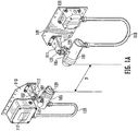
- the example open path gas detecting device may comprise a transmitter element 101 and a receiver element 103.
- the transmitter element 101 may be configured to produce, generate, emit, and/or trigger the production, generation, and/or emission of infrared light.
- the transmitter element 101 may comprise an infrared light source component that may produce, generate, and/or emit infrared light.
- Example infrared light source components may include, but are not limited to, gas discharge lamps, fluorescent lamps, heat lamps, and/or the like.
- gas discharge lamp refers to a type of artificial light source that may generate light by sending an energy discharge (such as electric discharge) through an ionized gas.
- the infrared light source component of the transmitter element 101 may comprise a xenon arc flashlamp.
- An example xenon arc flashlamp may produce, generate, and/or emit beams of light by discharging electricity through ionized xenon gas, and the light produced, generated, and/or emitted by the xenon arc flashlamp may comprise infrared light.
- xenon arc flashlamp as an example infrared light source component
- scope of the present disclosure is not limited to xenon arc flashlamps. Additionally, or alternatively, examples of the present disclosure may implement other type(s) of infrared light source component(s) for producing infrared light.
- the infrared light may be produced at an intense level by the infrared light source component of the transmitter element 101.
- the infrared light source component may be electronically coupled to a power source component, and the power source component may supply power to the infrared light source component to generate discharge energy for triggering infrared light.
- the example xenon arc flashlamp may produce infrared light that has a pulse frequency of 4 Hz, and each pulse of infrared light may have a duration of approximately one microsecond.
- the pulse frequency, extremely short duration of these pulses of light, and/or the shape of the discharge pulses may distinguish the infrared light generated by the xenon arc flashlamp from other natural and artificial sources of infrared light in the environment.
- the receiver element 103 may detect, measure, and/or identify infrared light produced by the xenon arc flashlamp of the transmitter element 101.
- examples of the present disclosure may include infrared light produced at a pulse frequency higher than or lower than 4 Hz. Additionally, or alternatively, examples of the present disclosure may include infrared light that have a duration of less than or more than one microsecond.
- the infrared light produced by the infrared light source component may be collimated.
- the transmitter element 101 may comprise one or more optical components (such as optical collimating lens) to redirect and/or adjust the direction of the infrared light generated by the infrared light source component.
- optical components such as optical collimating lens
- parallel beams of infrared light may be emitted from the transmitter element 101 through the infrared light source component and the one or more optical components.
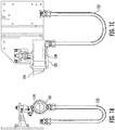
- FIG. 1B and FIG. 1C a front view and a side view of the transmitter element 101 are illustrated, respectively.
- the transmitter element 101 may comprise a housing 139, which may provide an enclosure for various components of the transmitter element 101 (for example, an infrared light source component and one or more optical components described above).
- the transmitter element 101 may comprise a conduit component 123.
- the conduit component 123 may be connected to the transmitter element 101, which may provide a protective enclosure for electrical wire(s) that may connect components within the housing 139 (for example, an infrared light source component) with components that are outside of housing 139 (for example, a power source component).
- infrared light generated by the infrared light source component may pass through the window lens component 119.
- the window lens component 119 may comprise glass and/or other transparent material that may allow the infrared light to pass through.
- the window lens component 119 may be heated to minimize condensation, frosting and/or buildup of snow.
- the transmitter element 101 may comprise an awning component (for example, the awning component 141 as shown in FIG. 1C ) that may protect the window lens component 119 from rain, snow, and/or other particles that may fall on the window lens component 119.
- the transmitter element 101 may be connected to an mounting bracket 111 through a pivot block 105.
- the transmitter element 101 may be connected to the pivot block 105 through a fastener 125 (such as a bolt and a nut).
- the pivot block 105 may be fastened to the mounting bracket 111 through a fastener 127 (such as a bolt and a nut).
- the transmitter element 101 may rotate to a desired angle, such that the transmitter element 101 may align with the receiver element 103.
- the transmitter element 101 may rotate around a horizontal axis.
- the pivot block 105 Prior to the fastener 127 being tightened, the pivot block 105 may rotate around a vertical axis, which may in turn cause the transmitter element 101 to rotate around the vertical axis.
- the transmitter element 101 may be connected and/or fastened to other components of the example open path gas detecting device through other means or in other ways.
- the mounting bracket 111 may be fastened to the mounting plate 109 through one or more fasteners (such as screws), and the mounting plate 109 may be fastened to a secured structure (for example, a wall) through one or more fasteners (such as screws).
- a junction box component 121 may be securely fastened to the mounting plate 109.
- the junction box component 121 may provide a protective enclosure for various components of the open path gas detecting device (such as a power source component, electric circuits including processing circuitry (such as a microcontroller), memory circuitry, and/or the like).
- the conduit component 123 may be connected to the transmitter element 101 and the junction box component 121, and one or more components within the junction box component 121 may be connected to components within the transmitter element 101 through electrical wire(s) that are disposed within the conduit component 123, as described above.
- the receiver element 103 may be configured to detect, measure, and/or identify the intensity level of the infrared light.
- the infrared light generated by the transmitter element 101 may travel through an optical path between the transmitter element 101 and the receiver element 103 (for example, the optical path D as shown in FIG. 1A ).
- the distance of the optical path D (for example, the distance between the window lens component 129 of the receiver element and the window lens component 119 of the transmitter element 101) may be between 5 meters to 350 meters. In some examples, the distance of the optical path D may have other values.
- FIG. 1D and FIG. IE a side view and a front view of the receiver element 103 are illustrated, respectively.
- gaseous substance along the optical path D may absorb at least some of the infrared light transmitted by the transmitter element 101.
- the infrared light may travel through the window lens component 129 of the receiver element 103, and the receiver element 103 may comprise at least one detector component to detect, measure, and/or identify the absorption level of the infrared light by the gaseous substance along the optical path D.
- the open path gas detecting device may detect, measure, and/or identify the concentration level of the gaseous substance.
- the receiver element 103 may comprise a sample detector component and a reference detector component.
- the receiver element 103 may comprise an optical component that may divide the infrared light into two or more portions (for example, but not limited to, a beam splitter component, a selective filter component (for example, a selective bandpass filter).
- the infrared light may travel through a sample filter component and arrive at the sample detector component.
- the gaseous substance to be detected (“target gaseous substance”) may absorb at least some of the infrared light
- the sample filter component may filter the infrared light at wavelength(s) and/or wavelength range(s) where the target gaseous substance may absorb the infrared light.
- the sample detector component may detect the intensity level of infrared light at such wavelength(s) and/or wavelength range(s) where target gaseous substance may absorb the infrared light.
- the infrared light may travel through a reference filter component and arrive at the reference detector component.
- the reference filter component may filter the infrared light at wavelength(s) and/or wavelength range(s) where the target gaseous substance may not or may be less likely to absorb the infrared light.
- the reference detector component may detect the intensity level of infrared light at such wavelength(s) and/or wavelength range(s) where target gaseous substance may not or may be less likely to absorb the infrared light.
- the example open path gas detecting device may determine the concentration level of target gaseous substance along the optical path D.
- the receiver element 103 may comprise a housing 131, which may provide an enclosure for various components of the receiver element 103 (for example, the sample detector component, the sample filter component, the reference detector component, and the reference filter component described above).
- the receiver element 103 may comprise a conduit component 133.
- the conduit component 133 may be connected to the receiver element 103, which may provide a protective enclosure for electrical wire(s) that may connect components within the housing 131 (for example, the sample detector component, the reference detector component) with components that are outside of housing 131.
- the sample detector component and the reference detector component may be connected to various electronic components to amplify, condition and/or process the signals received by the sample detector component and the reference detector component.
- the sample detector component and/or the reference detector component may be connected to a digital signal processor (DSP), which may be configured to perform signal processing calculations.
- DSP digital signal processor
- a microprocessor may be implemented to control the overall function of the open path gas detecting device.
- the microprocessor may be electronically coupled to the transmitter element 101 and/or the receiver element 103, and may perform the final calculations to determine reading of the concertation level of the target gaseous substance, and may output state of the open path gas detecting device.
- infrared light may travel through the window lens component 129 of the receiver element 103.
- the window lens component 129 may be heated to minimize condensation, frosting and/or buildup of snow.
- the level of heating applied to the window lens component 129 may be controlled by the microcontroller, and may be adjusted from zero to maximum depending on the temperature of the window lens component 129.
- the receiver element 103 may comprise an awning component (for example, the awning component 143 as shown in FIG. ID) that may protect the window lens component 129.
- the receiver element 103 may be connected to an mounting bracket 115 through a pivot block 107.
- the receiver element 103 may be connected to the pivot block 107 through a fastener 135 (such as a bolt and a nut).
- the pivot block 107 may be fastened to the mounting bracket 115 through a fastener 137 (such as a bolt and a nut).
- the receiver element 103 may rotate to a desired angle, such that the receiver element 103 may align with the transmitter element 101.
- the receiver element 103 may rotate around a horizontal axis.
- the pivot block 107 Prior to the fastener 137 being tightened, the pivot block 107 may rotate around a vertical axis, which may in turn cause the receiver element 103 to rotate around the vertical axis.
- receiver element 103 may be connected and/or fastened to other components of the example open path gas detecting device through other means or in other ways.
- the mounting bracket 115 may be fastened to the mounting plate 113 through one or more fasteners (such as screws), and the mounting plate 113 may be fastened to a secured structure (for example, a wall) through one or more fasteners (such as screws).
- a junction box component 117 may be securely fastened to the mounting plate 113.
- the junction box component 117 may provide a protective enclosure for various components of the open path gas detecting device (such as electronic components describe above).
- the conduit component 133 may be connected to the receiver element 103 and the junction box component 117, and one or more components within the junction box component 117 may be connected to components within the receiver element 103 through electrical wire(s) that are disposed within the conduit component 133, as described above.
- FIGS. 1A-1E illustrate various example components of an example open path gas detecting device
- an example open path gas detecting device may comprise less than or more than these example components as illustrated in FIGS. 1A-1E .
- an example open path gas detecting device may comprise other components, including but not limited to, aimer, viewfinder, and/or the like.
- FIG. 2 an example diagram illustrating various components of an example transmitter element 200 of an example open path gas detecting device is shown.
- the example transmitter element 200 may comprise an infrared light source component 202, an optical component 204, and a window lens component 206.
- the infrared light source component 202 may be disposed within the transmitter element 200.
- the infrared light source component 202 may be securely positioned on an inner surface of the transmitter element 200.
- the infrared light source component 202 may be configured to produce, generate, and/or emit infrared light.
- the infrared light source component 202 may comprise a xenon arc flashlamp.
- the xenon arc flashlamp may produce, generate, and/or emit beams of light by discharging energy through ionized xenon gas, and the light produced, generated, and/or emitted by the xenon arc flashlamp may comprise infrared light.
- the xenon arc flashlamp may be connected to a lamp drive component.
- the lamp drive component may comprise a power source component, which may provide a power source for the xenon arc flashlamp to discharge energy through ionized xenon gas as described above.
- the discharge energy level of the xenon arc flashlamp may be associated with the power provided by the power source component.
- the power source component may comprise a 24VDC power supply, which may be connected to the xenon arc flashlamp through electric wire(s).
- the power source component may comprise an adjustable power supply that may provide voltage to power the xenon arc flashlamp at one or more different levels.
- the voltage level of the adjustable power supply may be controlled by a microcontroller. The higher the voltage level provided to the xenon arc flashlamp, the higher the discharge energy that the xenon arc flashlamp may have.
- the xenon arc flashlamp when the xenon arc flashlamp is connected to the lamp drive component (for example, a power source component) and powered on, the xenon arc flashlamp may generate an arc 208.
- the arc 208 may produce, generate, and/or emit infrared light beams.
- the infrared light beams produced, generated, and/or emitted by the arc 208 may have a beam divergence value A.
- beam divergence refers to an angular measurement of an increase in the beam diameter (or radius) with respect to an increase of distance from the beam source (for example, the arc 208) where the beam emerges.
- the beam divergence value A may be affected by the size of the arc 208.
- a lower discharge energy of the xenon arc flashlamp may reduce the size of the arc 208, which in turn reduces the field angle (or divergence angle) of the beam after the optical component 204 (for example, silicon lens), resulting in a reduced angular spread of the beam.
- the primary effect of reducing discharge energy may be to reduce the size of the arc 208.
- the smaller arc size may result in a more tightly collimated beam from the transmitter after the silicon lens.
- divergence value A may not change significantly with discharge energy and the size of the arc 208.
- the size of the arc 208 may be a function of the discharge energy of the xenon arc flashlamp. For example, the higher the discharge energy, the larger the size of the arc 208.
- the beam divergence value A may be modulated between two or more values by periodically adjusting or changing the discharge energy of the xenon arc flashlamp.
- the optical component 204 may be disposed within the transmitter element 200.
- the edge of the optical component 204 may be securely attached on an inner surface of the transmitter element 200.
- the optical axis of the optical component 204 (for example, the central axis of the optical component 204) may be aligned with the infrared light source component 202.
- the optical component 204 may be positioned such that the optical axis may pass through the center of the arc 208.
- the optical component 204 may be structurally connected to the transmitter element 200 in other ways.
- the optical component 204 may be configured to collimate the infrared light beams generated by the arc 208.
- the optical component 204 may comprise one or more optical collimating lens, such as but not limited to one or more lens having spherical surface(s), one or more lens having parabolic surface(s) and/or the like.
- the optical component 204 may comprise silicon meniscus lens.
- the infrared light beams generated by the arc 208 may pass through the optical component 204, and the infrared light beams may be collimated by the optical component 204 into parallel or approximately parallel rays of infrared light.
- the optical component 204 may have an effective focal length of seventy-five millimeters. In some examples, the optical component 204 may have an effective focal length of other value(s).
- the infrared light beams may pass through the window lens component 206 of the transmitter element 200.
- an example transmitter element may comprise less than or more than those components illustrated in FIG. 2 .
- a processor circuitry such as a microcontroller
- At least a portion of the infrared light beams emitted from the transmitter element 200 may be absorbed by the gaseous substance along the optical path between the transmitter element 200 and a receiver element of the example open path gas detecting device, and the receiver element may comprise one or more detector components to detect, measure, and/or identify the intensity level of infrared light.
- the open path gas detecting device may produce an accurate reading.
- the direction of infrared light emitted by the transmitter element may be accessed or evaluated to determine if the transmitter element is aligned correctly to the receiver element.
- the receiver element may generate a measurement corresponding to the intensity level of the infrared light received by the receiver element, and the measurement may be compared against an predetermined value (for example, an expected intensity level of the infrared light if the transmitter element is aligned correctly to the receiver element).
- the transmitter element Based on the measurement equals to or approximates the predetermined value, it may be determined that the transmitter element is aligned correctly to the receiver element. Based on the difference between the measurement and the predetermined value exceeding the predetermined threshold, it may be determined that the transmitter element is not aligned correctly to the receiver element.
- the alignment of the receiver element may also directly influence the received infrared light intensity by the receiver element, and it can be technical challenging to differentiate between an alignment error in the transmitter element and an alignment error of the receiver element.
- the received infrared light intensity at the receiver element may be affected by the light transmission through window lens component of the receiver element and/or the transmitter element and by light absorption along the optical path.
- the receiver element detects, measures, and/or identifies a lower than expected intensity level of infrared light, it can be technical challenging to determine whether the lower than expected intensity level is caused by an alignment error of the transmitter element or caused by light absorption due to for example, dirt on the window lens component.
- an example flowchart illustrates an example method 300 in accordance with examples of the present disclosure.
- the example method 300 may provide technical solutions for diagnosing misalignment of the transmitter element.
- the example method 300 may overcome the technical challenges discussed above.
- each block of the flowchart, and combinations of blocks in the flowchart may be implemented by various means such as hardware, firmware, circuitry and/or other devices associated with execution of software including one or more computer program instructions.
- one or more of the procedures described in FIG. 3 may be embodied by computer program instructions, which may be stored by a non-transitory memory of an apparatus employing an example of the present disclosure and executed by a processor in the apparatus.
- These computer program instructions may direct one or more components of the transmitter element and/or the receiver element of the open path gas detecting device to function in a particular manner, such that the instructions stored in the computer-readable storage memory produce an article of manufacture, the execution of which implements the function specified in the flowchart block(s).
- the processor may be embodied in a number of different ways.
- the processor may be embodied as one or more complex programmable logic devices (CPLDs), microprocessors, multi-core processors, coprocessing entities, application-specific instruction-set processors (ASIPs), microcontroller and/or controllers.
- CPLDs complex programmable logic devices
- ASIPs application-specific instruction-set processors
- the processor may be embodied as one or more other processing devices or circuitry.
- the term circuitry may refer to an entirely hardware example or a combination of hardware and computer program products.
- the processor may be embodied as integrated circuits, application specific integrated circuits (ASICs), field programmable gate arrays (FPGAs), programmable logic arrays (PLAs), hardware accelerators, other circuitry, and/or the like.
- ASICs application specific integrated circuits
- FPGAs field programmable gate arrays
- PLAs programmable logic arrays
- the processor may be configured for a particular use or configured to execute instructions stored in volatile or non-volatile media or otherwise accessible to the processor.
- the processor may be capable of performing steps or operations according to examples of the present disclosure when configured accordingly.
- the non-transitory memory may include one or more non-volatile storage or storage media, such as hard disks, ROM, PROM, EPROM, EEPROM, flash memory, MMCs, SD memory cards, Memory Sticks, CBRAM, PRAM, FeRAM, RRAM, SONOS, racetrack memory, and/or the like.
- the non-transitory memory may store databases, database instances, applications, programs, program modules, scripts, source code, object code, byte code, compiled code, interpreted code, machine code, executable instructions, and/or the like.
- examples of the present disclosure may be configured as methods, devices, and the like. Accordingly, examples may comprise various means including entirely of hardware or any combination of software and hardware. Furthermore, examples may take the form of a computer program product on at least one non-transitory computer-readable storage medium having computer-readable program instructions (e.g., computer software) embodied in the storage medium. Similarly, examples may take the form of a computer program code stored on at least one non-transitory computer-readable storage medium. Any suitable computer-readable storage medium may be utilized including non-transitory hard disks, CD-ROMs, flash memory, optical storage devices, or magnetic storage devices.
- the example method 300 may start at block 301.
- a processing circuitry for example, a microcontroller electronically coupled to a transmitter element and/or a receiver element of an example open path gas detecting device
- the infrared light source component may comprise a xenon arc flashlamp.
- the xenon arc flashlamp may produce, generate, and/or emit beams of infrared light by discharging electricity through ionized xenon gas.
- the xenon arc flashlamp when the xenon arc flashlamp is connected to the lamp drive component (for example, a power source component) and powered on, the xenon arc flashlamp may generate an arc.
- the processing circuitry may cause the infrared light source component to generate first infrared light triggered at a first discharge energy level of the infrared light source component.
- the processing circuitry may cause the power source component to supply power at a first voltage level (also referred to as a first voltage level power) to the xenon arc flashlamp.
- the first voltage level may be a baseline voltage level such as 24 VDC.
- the first voltage level may have other values.
- the first voltage level may provide a first discharge energy level to the xenon arc flashlamp, and the xenon arc flashlamp may generate the first infrared light in response to and/or triggered by the first discharge energy level.
- a processing circuitry may cause the at least one detector component to generate a first light intensity indication.
- the first light intensity indication may correspond to the first infrared light generated by the transmitter element and triggered at the first discharge energy level.
- the first light intensity indication may indicate a first intensity level of the first infrared light received by the receiver element.
- the receiver element may comprise one or more detector components that may detect, measure, and/or identify the intensity level of the beam of the infrared light.
- the one or more detector components may generate one or more signals that may indicate the first intensity level of the first infrared light received by the receiver element.
- the receiver element may process the one or more signals through one or more processors (such as a digital signal processor and/or a microprocessor as described above) to generate the first light intensity indication corresponding to the first infrared light received by the receiver element.
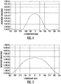
- example diagrams illustrate example irradiance levels of the first infrared light received by the receiver element.
- the term "irradiance" refers to a measure of radiant power received by a surface or a plane per unit area.
- FIG. 4 illustrates the irradiance levels of the first infrared light received by the receiver element at a horizontal plane of the receiver element.
- FIG. 5 illustrates the irradiance levels of the first infrared light received by the receiver element at a vertical plane of the receiver element.
- these example irradiance levels may be determined based on the first light intensity indication generated by the receiver element.
- a processing circuitry may cause the infrared light source component to generate second infrared light.
- the second infrared light may be triggered at a second discharge energy level.
- the second discharge energy level may be different from the first discharge energy level described above in connection with block 303.
- the processing circuitry may cause the power source component to supply power at a second voltage level (also referred to as a second voltage level power) to the xenon arc flashlamp.
- the second voltage level may be a reduced voltage level such as 12 VDC.
- the second voltage level may have other values.
- the second voltage level may provide a second discharge energy level to the xenon arc flashlamp, and the xenon arc flashlamp may generate the second infrared light in response to and/or triggered by the second discharge energy level.
- a processing circuitry may cause the at least one detector component to generate a second light intensity indication.
- the second light intensity indication may correspond to the second infrared light generated by the transmitter element at the second discharge energy level.
- the second light intensity indication may indicate a second intensity level of the second infrared light received by the receiver element
- FIG. 6 and FIG. 7 example diagrams illustrating example irradiance levels of the second infrared light received by the receiver element.
- FIG. 6 illustrates the irradiance levels of the second infrared light received by the receiver element at a horizontal plane of the receiver element.
- FIG. 7 illustrates the irradiance levels of the second infrared light received by the receiver element at a vertical plane of the receiver element.
- these example irradiance levels may be determined based on the second light intensity indication generated by the receiver element.
- the beam divergence value in the horizontal plane decreases as the discharge energy decreases from the first discharge energy level to the second discharge energy level. Comparing FIG. 7 and FIG. 5 , the beam divergence value in the vertical plane also decreases as the discharge energy decreases from the first discharge energy level to the second discharge energy level.
- the processing circuitry may generate an alignment indication based at least in part on the first light intensity indication and the second light intensity indication.
- the alignment indication may indicate whether the transmitter element is misaligned to the receiver element.
- the first light intensity indication may indicate a first intensity level of the first infrared light received by the receiver element
- the second light intensity indication may indicate a second intensity level of the second infrared light received by the receiver element.
- the processing circuitry may calculate a ratio value between first intensity level and the second intensity level.
- a processing circuitry may determine whether the ratio value satisfies a predetermined threshold.
- the ratio value may be affected if the alignment of the transmitter element degrades. For example, when the transmitter element is correctly aligned with the receiver element, an alignment angle between a central axis of the transmitter element and a central axis of the receiver element is zero, and the ratio value may be at a predetermined value or within a predetermined threshold based on the first discharge energy and the second discharge energy. As the alignment of the transmitter element degrades, the alignment angle may increase, result in a change of the ratio value.
- the predetermined value and/or the predetermined threshold may be determined or calculated when the transmitter element is correctly aligned to the receiver element. For example, during the initial installation of the transmitter element, the processing circuitry may determine the predetermined value and/or the predetermined threshold. Additionally, or alternatively, the predetermined value and/or the predetermined threshold may be determined based on, for example but not limited to, a system requirement that may correspond to a system toleration of the misalignment of the transmitter element.
- examples of the present disclosure may remove the dependency on absolute values to diagnose transmitter element misalignment, and may overcome technical challenges discussed above.
- the processing circuitry may determine that there is no misalignment of the transmitter element at block 313.
- the processing circuitry may determine that the ratio value satisfies the predetermined threshold.
- the processing circuitry may generate the alignment indication to indicate that the transmitter element is not misaligned to the receiver element.
- the processing circuitry may determine that there is misalignment of the transmitter element at block 315.
- the processing circuitry may determine that the ratio value does not satisfy the predetermined threshold.
- the processing circuitry may generate the alignment indication to indicate that the transmitter element is misaligned to the receiver element.
- the processing circuitry may generate a warning signal that may caution an operator of the open path gas detecting device on the misalignment of the transmitter element (for example, an electronic message rendered for display on a user interface of a device associated with the operator, an alert sound generated by a speaker element installed in the environment near the operator, and/or the like).
- the example method 300 ends at block 317.
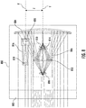
- FIG. 8 an example diagram illustrating various components of an example receiver element 800 of an example open path gas detecting device is shown.
- the example receiver element 800 may comprise various components for detecting, measuring, and/or identifying an intensity level of the infrared light received by the receiver element 800.
- the receiver element 800 may receive infrared light that is generated by an example transmitter element of an example open path gas detecting device, and travelled through the optical path and the window lens component 802 of the receiver element 800.
- the infrared light may be redirected by a mirror component 804 to a detection channel 806.
- the detection channel 806 may comprise a sample detector component 808 and a reference detector component 810.
- the infrared light may travel through a sample filter component 812 and arrive at the sample detector component 808.
- the target gaseous substance may absorb infrared light
- the sample filter component 812 may filter the infrared light at wavelength(s) and/or wavelength range(s) where the target gaseous substance may absorb the infrared light.
- the sample detector component 808 may detect the intensity level of infrared light at such wavelength(s) and/or wavelength range(s) where target gaseous substance may absorb the infrared light.
- the infrared light may travel through a reference filter component 814 and arrive at the reference detector component 810.
- the reference filter component 814 may filter the infrared light at wavelength(s) and/or wavelength range(s) where the target gaseous substance may not or may be less likely to absorb the infrared light.
- the reference detector component 810 may detect the intensity level of infrared light at such wavelength(s) and/or wavelength range(s) where target gaseous substance may not or may be less likely to absorb the infrared light.
- the example open path gas detecting device may determine the concentration level of target gaseous substance along the optical path.
- the example receiver element 800 may transmit data and/or signal associated with the concentration level of target gaseous substance to a connected control system (for example, to a processing circuitry such as a microcontroller).
- the example receiver element 800 may implement functionality, in some examples, for installation, commissioning, and maintenance of the open path gas detecting device.
- the sample filter component 812, the sample detector component 808, the reference filter component 814, and the reference detector component 810 may be disposed within the receiver element 800.
- each of the sample filter component 812, the sample detector component 808, the reference filter component 814, and the reference detector component 810 may be securely positioned with respect an inner surface of the receiver element 800 through one or more supporting beams and/or other supporting structure.
- the sample filter component 812, the sample detector component 808, the reference filter component 814, and the reference detector component 810 may be positioned in a coaxial arrangement with one another, such that, for example, an optical axis Y of the detection channel 806 may pass through the center of the sample filter component 812, the center of the sample detector component 808, the center of the reference filter component 814, and the center of the reference detector component 810.
- an example detection channel may additionally or alternatively include other components, and/or various components of the example detection channel may be positioned differently than those shown in FIG. 8 .
- the receiver element may generate a measurement corresponding to the intensity level of the infrared light received by the receiver element, and the measurement may be compared against an predetermined value (for example, an expected intensity level of infrared light if the receiver element is aligned correctly to the transmitter element). Based on the measurement equals to or approximates the predetermined value, it may be determined that the receiver element is aligned correctly to the transmitter element. Based on the ratio between the measurement and the predetermined value exceeding the predetermined threshold, it may be determined that the receiver element is not aligned correctly to the transmitter element.
- an predetermined value for example, an expected intensity level of infrared light if the receiver element is aligned correctly to the transmitter element.
- the alignment of the transmitter element may also directly influence the received infrared light intensity at the receiver element. It can be technical challenging to differentiate between an alignment error in the transmitter element and an alignment error of the receiver element.
- the received infrared light intensity at the receiver element may be affected by the light transmission through window lens component of the receiver element and/or the transmitter element and by light absorption along the optical path.
- the receiver element detects, measures, and/or identifies a lower than expected intensity level of infrared light, it can be technical challenging to determine whether the lower than expected intensity level is caused by an alignment error of the receiver element or caused by light absorption due to for example, dirt on the window lens component. Additionally, the design of the receiver element may be optimized such that the receiver element may be insensitive to small errors in alignment. In other words, a significant misalignment of the receiver element may need to occur before any reduction in the intensity level may be detected by the receiver element.
- the example receiver element 800 may comprise a diagnosis channel 816.
- the diagnosis channel 816 may comprise an optical component 818 and a detector component 820.
- the optical component 818 may comprise a silicon lens, which may direct the infrared light to the detector component 820.
- the detector component 820 may be configured to generate a light intensity indication that may indicate the intensity level of the received infrared light.
- a surface of the detector component 820 may comprise a photodiode active area that may detect, measure, and/or identify intensity level of the infrared light.
- the photodiode active area may comprise indium gallium arsenide (InGaAs).
- the optical component 818 and the detector component 820 may be disposed within the receiver element 800.
- each of the optical component 818 and the detector component 820 may be securely positioned with respect an inner surface of the receiver element 800 through one or more supporting beams and/or other supporting structure.
- the optical component 818 and the detector component 820 may be positioned in a coaxial arrangement with one another, such that an optical axis X of the diagnosis channel 816 may pass through the center of the optical component 818 and the center of the detector component 820.
- diagnosis channel 816 While the above description illustrates some example components of the diagnosis channel 816, it is noted that the scope of the present disclosure is not limited to these example components only.
- an example diagnosis channel of the present disclosure may additionally or alternatively include other components, and/or various components of the example diagnosis channel may be positioned differently than those shown in FIG. 8 .
- the diagnosis channel 816 may be disposed in a parallel arrangement with the detection channel 806.
- an optical axis X of the diagnosis channel 816 (which may, for example, correspond to the central axis of the optical component 818 and/or the central axis of detector component 820) may be parallel to an optical axis Y of the detection channel 806 (which may, for example, correspond to the central axis of the sample filter component 812, the central axis of the sample detector component 808, the central axis of the reference filter component 814, and/or the central axis of the reference detector component 810).
- the diagnosis channel 816 may be disposed at an offset distance from the detection channel 806.
- the optical axis X of the diagnosis channel 816 may be at a distance Z from the optical axis Y of the detection channel 806.
- an effective field of view of the diagnosis channel 816 may be less than an effective field of view of the detection channel 806.
- the size of the photodiode active area of the detector component 820 of the diagnosis channel 816 may be smaller than the size of the photodiode active area of the reference detector component 810 of the detection channel 806 and/or the size of the photodiode active area of the sample detector component 808 of the detection channel 806.
- the photodiode active area of the detector component 820 of the diagnosis channel 816 may have a diameter of 0.3 millimeter
- the photodiode active area of the reference detector component 810 of the detection channel 806 and/or the photodiode active area of the sample detector component 808 of the detection channel 806 may have a diameter of 1.1 millimeters.
- the photodiode active area of the detector component 820, the photodiode active area of the reference detector component 810, and/or the photodiode active area of sample detector component 808 may have other size value(s).
- the diagnosis channel 816 may be arranged parallel to but offset from the detection channel 806, and the diagnosis channel 816 may have an effective field of view smaller than the effective field of view of the detection channel 806. As such, the intensity level of infrared light detected by the diagnosis channel 816 may be different from the intensity level of infrared light detected by the detection channel 806.
- the ratio between the intensity level of infrared light detected on the diagnosis channel 816 and the intensity level of infrared light detected on the detection channel 806 may be affected by the degree of misalignment of the receiver element 800.
- the higher the degree of the misalignment of the receiver element 800 the higher the ratio between the intensity level of infrared light detected on the diagnosis channel 816 and the intensity level of infrared light detected on the detection channel 806.
- misalignment of the receiver element 800 may be detected.
- an example flowchart illustrates an example method 900 in accordance with examples of the present disclosure.
- the example method 900 may provide technical solutions for diagnosing misalignment of the receiver element.
- the example method 900 may overcome the technical challenges discussed above.
- each block of the flowchart, and combinations of blocks in the flowchart may be implemented by various means such as hardware, firmware, circuitry and/or other devices associated with execution of software including one or more computer program instructions. Accordingly, examples of the present disclosure may be configured as methods, devices, and the like, and may comprise various means including entirely of hardware or any combination of software and hardware. Furthermore, examples may take the form of a computer program product on at least one non-transitory computer-readable storage medium having computer-readable program instructions (e.g., computer software) embodied in the storage medium.
- the example method 900 may start at block 901.
- a processing circuitry (for example, a microcontroller electronically coupled to a receiver element of an example open path gas detecting device) may cause a detection channel to generate a first light intensity indication.
- an example receiver element may comprise a detection channel and a diagnosis channel.
- each of the detection channel and the diagnosis channel may be configured to generate a light intensity indication corresponding to infrared light received by the receiver element.
- the detection channel may comprise a sample detector component and/or a reference detector component, which may be configured to generate a light intensity indication indicating an intensity level of the infrared light received through the detection channel.
- a processing circuitry (for example, a microcontroller electronically coupled to a receiver element of an example open path gas detecting device) may cause the diagnosis channel to generate a second light intensity indication.
- the diagnosis channel may comprise a detector component, which may be configured to generate a light intensity indication indicating an intensity level of the infrared light received through the diagnosis channel.
- a processing circuitry may determine whether the ratio value between the first light intensity indication and the second light intensity indication satisfies a predetermined value and/or a predetermined threshold.
- the predetermined value and/or the predetermined threshold may be determined or calculated when the receiver element is correctly aligned to the transmitter element. For example, during the initial installation of the receiver element, the processing circuitry may determine the predetermined value and/or the predetermined threshold. Additionally, or alternatively, the predetermined value and/or the predetermined threshold may be determined based on, for example but not limited to, a system requirement that may corresponds to a system toleration of the misalignment of the receiver element.
- the processing circuitry may determine that there is no misalignment of the receiver element at block 909.
- the processing circuitry may determine that the ratio value satisfies the predetermined threshold.
- the processing circuitry may generate the alignment indication to indicate that the receiver element is not misaligned to the transmitter element.
- the processing circuitry may determine that there is misalignment of the transmitter element at block 911.
- the processing circuitry may determine that the ratio value does not satisfy the predetermined threshold.
- the processing circuitry may generate the alignment indication to indicate that the receiver element is misaligned to the transmitter element.
- the processing circuitry may generate a warning signal that may caution an operator of the open path gas detecting device on the misalignment of the receiver element (for example, an electronic message rendered for display on a user interface of a device associated with the operator, an alert sound generated by a speaker element installed in the environment near the operator, and/or the like).
- the example method 900 may end at block 913.
- various examples of the present disclosure may generate one or more alignment indications that may indicate whether the transmitter element or the receiver element is correctly aligned.
- alignment indications may be generated by a microcontroller in accordance with examples of the present disclosure, which may facilitate an improvement in diagnostic capability, enable each misalignment condition to be differentiated, and direct the operator to take appropriate action.
- the microcontroller may generate an alignment indication that may indicate the transmitter element is misaligned based on, for example, those described above in connection with FIG. 2 to FIG. 7 .
- the microcontroller may calculate a ratio value between the first light intensity indication (derived from the first discharge energy level) and the second light intensity indication (derived from the second discharge energy level). Based on determining that the ratio value exceeds a predetermined threshold, the microcontroller may generate an alignment indication indicating that the transmitter element is misaligned.
- the microcontroller may generate an alignment indication that may indicate the receiver element is misaligned based on, for example, those described above in connection with FIG. 8 to FIG. 9 .
- the microcontroller may calculate a ratio value between the first light intensity indication (derived from the detection channel) and the second light intensity indication (derived from the diagnosis channel). Based on determining that the ratio value exceeds a predetermined threshold, the microcontroller may generate an alignment indication indicating that the receiver element is misaligned.
- the microcontroller may generate an indication that may indicate whether there is obstruction of infrared light along the optical path.
- the effective field of view of the diagnosis channel may be smaller than the effective field of view of the detection channel, and the diagnosis channel may be in a parallel arrangement but offset from the detection channel.
- the detection channel may detect a reduction in intensity level of infrared light
- the diagnosis channel may detect a disproportional change in the intensity level of infrared light
- the microcontroller may determine that there is at least partial obscuration of infrared light along the optical path (for example, an object moving along the optical path and blocking the infrared light, buildup of dust or dirt on window lens components). Accordingly, the microcontroller may generate an indication indicating that there is obstruction of infrared light along the optical path.
Landscapes
- Physics & Mathematics (AREA)
- Spectroscopy & Molecular Physics (AREA)
- Health & Medical Sciences (AREA)
- Life Sciences & Earth Sciences (AREA)
- Chemical & Material Sciences (AREA)
- Analytical Chemistry (AREA)
- Biochemistry (AREA)
- General Health & Medical Sciences (AREA)
- General Physics & Mathematics (AREA)
- Immunology (AREA)
- Pathology (AREA)
- Engineering & Computer Science (AREA)
- Mathematical Physics (AREA)
- Theoretical Computer Science (AREA)
- Investigating Or Analysing Materials By Optical Means (AREA)
Priority Applications (1)
| Application Number | Priority Date | Filing Date | Title |
|---|---|---|---|
| EP23188063.4A EP4257941A3 (fr) | 2020-04-24 | 2021-04-12 | Procédés, appareils et systèmes de diagnostic de désalignement dans des dispositifs de détection de gaz |
Applications Claiming Priority (1)
| Application Number | Priority Date | Filing Date | Title |
|---|---|---|---|
| US16/858,291 US11674894B2 (en) | 2020-04-24 | 2020-04-24 | Methods, apparatuses, and systems for diagnosing misalignment in gas detecting devices |
Related Child Applications (1)
| Application Number | Title | Priority Date | Filing Date |
|---|---|---|---|
| EP23188063.4A Division EP4257941A3 (fr) | 2020-04-24 | 2021-04-12 | Procédés, appareils et systèmes de diagnostic de désalignement dans des dispositifs de détection de gaz |
Publications (2)
| Publication Number | Publication Date |
|---|---|
| EP3901616A1 true EP3901616A1 (fr) | 2021-10-27 |
| EP3901616B1 EP3901616B1 (fr) | 2023-08-16 |
Family
ID=75497799
Family Applications (2)
| Application Number | Title | Priority Date | Filing Date |
|---|---|---|---|
| EP23188063.4A Pending EP4257941A3 (fr) | 2020-04-24 | 2021-04-12 | Procédés, appareils et systèmes de diagnostic de désalignement dans des dispositifs de détection de gaz |
| EP21167949.3A Active EP3901616B1 (fr) | 2020-04-24 | 2021-04-12 | Procédés, appareils et systèmes de diagnostic de désalignement dans des dispositifs de détection de gaz |
Family Applications Before (1)
| Application Number | Title | Priority Date | Filing Date |
|---|---|---|---|
| EP23188063.4A Pending EP4257941A3 (fr) | 2020-04-24 | 2021-04-12 | Procédés, appareils et systèmes de diagnostic de désalignement dans des dispositifs de détection de gaz |
Country Status (2)
| Country | Link |
|---|---|
| US (3) | US11674894B2 (fr) |
| EP (2) | EP4257941A3 (fr) |
Families Citing this family (1)
| Publication number | Priority date | Publication date | Assignee | Title |
|---|---|---|---|---|
| DE102024103590A1 (de) * | 2024-02-08 | 2025-08-14 | Msa Europe Gmbh | Vorrichtung und verfahren zur unterstützung der ausrichtung eines open path gasdetektors |
Citations (3)
| Publication number | Priority date | Publication date | Assignee | Title |
|---|---|---|---|---|
| US20120307241A1 (en) * | 2011-05-31 | 2012-12-06 | General Electric Company | Auto-aligning spectroscopy system |
| US9207170B2 (en) * | 2012-04-14 | 2015-12-08 | Dräger Safety AG & Co. KGaA | Gas detector system |
| US10620045B2 (en) * | 2014-08-22 | 2020-04-14 | Spectrasensors, Inc. | Spectrometer with active beam steering |
Family Cites Families (4)
| Publication number | Priority date | Publication date | Assignee | Title |
|---|---|---|---|---|
| US9106336B1 (en) | 2012-09-14 | 2015-08-11 | Google Inc. | Photo-sensor array to adjust alignment of optical receiver |
| CN106018339B (zh) * | 2016-07-08 | 2018-09-07 | 山东微感光电子有限公司 | 自适应反射式红外激光工业危险泄漏气体监测装置 |
| JP6930548B2 (ja) * | 2017-01-26 | 2021-09-01 | 日本電気株式会社 | 検知システム及び検知方法 |
| EP3467588A1 (fr) * | 2017-10-03 | 2019-04-10 | ASML Netherlands B.V. | Procédé et appareil de détermination des propriétés d'alignement d'un faisceau de rayonnement |
-
2020
- 2020-04-24 US US16/858,291 patent/US11674894B2/en active Active
-
2021
- 2021-04-12 EP EP23188063.4A patent/EP4257941A3/fr active Pending
- 2021-04-12 EP EP21167949.3A patent/EP3901616B1/fr active Active
-
2023
- 2023-05-02 US US18/311,146 patent/US12117393B2/en active Active
-
2024
- 2024-09-11 US US18/882,459 patent/US20250085218A1/en active Pending
Patent Citations (3)
| Publication number | Priority date | Publication date | Assignee | Title |
|---|---|---|---|---|
| US20120307241A1 (en) * | 2011-05-31 | 2012-12-06 | General Electric Company | Auto-aligning spectroscopy system |
| US9207170B2 (en) * | 2012-04-14 | 2015-12-08 | Dräger Safety AG & Co. KGaA | Gas detector system |
| US10620045B2 (en) * | 2014-08-22 | 2020-04-14 | Spectrasensors, Inc. | Spectrometer with active beam steering |
Also Published As
| Publication number | Publication date |
|---|---|
| US20210333202A1 (en) | 2021-10-28 |
| EP4257941A3 (fr) | 2023-12-20 |
| EP3901616B1 (fr) | 2023-08-16 |
| EP4257941A2 (fr) | 2023-10-11 |
| US11674894B2 (en) | 2023-06-13 |
| US20230266238A1 (en) | 2023-08-24 |
| US20250085218A1 (en) | 2025-03-13 |
| US12117393B2 (en) | 2024-10-15 |
Similar Documents
| Publication | Publication Date | Title |
|---|---|---|
| US7986408B2 (en) | Apparatus and method for in-flight detection of airborne water droplets and ice crystals | |
| US5008559A (en) | Method for operating an optical smoke detector and optical smoke detector for the method | |
| CA2953696C (fr) | Parametres relatifs aux nuages detectes optiquement au moyen de mesures d'echantillonnage analogique de la reflexion lumineuse | |
| US3335285A (en) | Photoelectric system for detecting objects in a zone including vibrating light source | |
| US20250085218A1 (en) | Methods, apparatuses, and systems for diagnosing misalignment in gas detecting devices | |
| EP3470877B1 (fr) | Détection de cible dur pour des systèmes optiques | |
| US9671325B2 (en) | Particle measuring device | |
| CN108761486A (zh) | 基于Scheimpflug原理的新型激光雷达系统 | |
| US20180313736A1 (en) | Controlled sampling volume of clouds for measuring cloud parameters | |
| JP6755105B2 (ja) | 炎検知器 | |
| CN100451621C (zh) | 高精度前向多角度大气散射测量方法 | |
| JP2015052465A (ja) | 天気判別システム | |
| CN107314958B (zh) | 一种带自定标装置的激光粉尘浓度测量装置及方法 | |
| JPH0844973A (ja) | 走査型火災検出装置 | |
| KR20180085336A (ko) | 통합기상검지기 | |
| JPH06331543A (ja) | 浮遊粒子濃度計測装置 | |
| CN113552086B (zh) | 用于改进气体检测设备的方法、装置和系统 | |
| CN110850392A (zh) | 激光雷达退偏增益比的校正方法 | |
| CN114002310B (zh) | 带有抗震动性能的顺磁氧传感器 | |
| JP3205346B2 (ja) | 直接電磁エネルギと反射電磁エネルギを弁別するシステム | |
| JPS60129646A (ja) | 缶内部塗装膜検出器 | |
| CN216116149U (zh) | 一种高速公路能见度及降水量检测器 | |
| RU133606U1 (ru) | Базисный фотометр | |
| KR101299527B1 (ko) | 창 오염 측정 장치 및 방법 | |
| KR101371195B1 (ko) | 레이저를 이용한 감지 영역별 감도 차등화 시스템 |
Legal Events
| Date | Code | Title | Description |
|---|---|---|---|
| PUAI | Public reference made under article 153(3) epc to a published international application that has entered the european phase |
Free format text: ORIGINAL CODE: 0009012 |
|
| STAA | Information on the status of an ep patent application or granted ep patent |
Free format text: STATUS: REQUEST FOR EXAMINATION WAS MADE |
|
| 17P | Request for examination filed |
Effective date: 20210412 |
|
| AK | Designated contracting states |
Kind code of ref document: A1 Designated state(s): AL AT BE BG CH CY CZ DE DK EE ES FI FR GB GR HR HU IE IS IT LI LT LU LV MC MK MT NL NO PL PT RO RS SE SI SK SM TR |
|
| B565 | Issuance of search results under rule 164(2) epc |
Effective date: 20210903 |
|
| GRAP | Despatch of communication of intention to grant a patent |
Free format text: ORIGINAL CODE: EPIDOSNIGR1 |
|
| STAA | Information on the status of an ep patent application or granted ep patent |
Free format text: STATUS: GRANT OF PATENT IS INTENDED |
|
| INTG | Intention to grant announced |
Effective date: 20230316 |
|
| GRAS | Grant fee paid |
Free format text: ORIGINAL CODE: EPIDOSNIGR3 |
|
| GRAA | (expected) grant |
Free format text: ORIGINAL CODE: 0009210 |
|
| STAA | Information on the status of an ep patent application or granted ep patent |
Free format text: STATUS: THE PATENT HAS BEEN GRANTED |
|
| AK | Designated contracting states |
Kind code of ref document: B1 Designated state(s): AL AT BE BG CH CY CZ DE DK EE ES FI FR GB GR HR HU IE IS IT LI LT LU LV MC MK MT NL NO PL PT RO RS SE SI SK SM TR |
|
| REG | Reference to a national code |
Ref country code: CH Ref legal event code: EP Ref country code: DE Ref legal event code: R096 Ref document number: 602021004244 Country of ref document: DE |
|
| REG | Reference to a national code |
Ref country code: IE Ref legal event code: FG4D |
|
| REG | Reference to a national code |
Ref country code: LT Ref legal event code: MG9D |
|
| REG | Reference to a national code |
Ref country code: NL Ref legal event code: MP Effective date: 20230816 |
|
| REG | Reference to a national code |
Ref country code: AT Ref legal event code: MK05 Ref document number: 1600510 Country of ref document: AT Kind code of ref document: T Effective date: 20230816 |
|
| PG25 | Lapsed in a contracting state [announced via postgrant information from national office to epo] |
Ref country code: GR Free format text: LAPSE BECAUSE OF FAILURE TO SUBMIT A TRANSLATION OF THE DESCRIPTION OR TO PAY THE FEE WITHIN THE PRESCRIBED TIME-LIMIT Effective date: 20231117 |
|
| PG25 | Lapsed in a contracting state [announced via postgrant information from national office to epo] |
Ref country code: IS Free format text: LAPSE BECAUSE OF FAILURE TO SUBMIT A TRANSLATION OF THE DESCRIPTION OR TO PAY THE FEE WITHIN THE PRESCRIBED TIME-LIMIT Effective date: 20231216 |
|
| PG25 | Lapsed in a contracting state [announced via postgrant information from national office to epo] |
Ref country code: SE Free format text: LAPSE BECAUSE OF FAILURE TO SUBMIT A TRANSLATION OF THE DESCRIPTION OR TO PAY THE FEE WITHIN THE PRESCRIBED TIME-LIMIT Effective date: 20230816 Ref country code: RS Free format text: LAPSE BECAUSE OF FAILURE TO SUBMIT A TRANSLATION OF THE DESCRIPTION OR TO PAY THE FEE WITHIN THE PRESCRIBED TIME-LIMIT Effective date: 20230816 Ref country code: PT Free format text: LAPSE BECAUSE OF FAILURE TO SUBMIT A TRANSLATION OF THE DESCRIPTION OR TO PAY THE FEE WITHIN THE PRESCRIBED TIME-LIMIT Effective date: 20231218 Ref country code: NO Free format text: LAPSE BECAUSE OF FAILURE TO SUBMIT A TRANSLATION OF THE DESCRIPTION OR TO PAY THE FEE WITHIN THE PRESCRIBED TIME-LIMIT Effective date: 20231116 Ref country code: NL Free format text: LAPSE BECAUSE OF FAILURE TO SUBMIT A TRANSLATION OF THE DESCRIPTION OR TO PAY THE FEE WITHIN THE PRESCRIBED TIME-LIMIT Effective date: 20230816 Ref country code: LV Free format text: LAPSE BECAUSE OF FAILURE TO SUBMIT A TRANSLATION OF THE DESCRIPTION OR TO PAY THE FEE WITHIN THE PRESCRIBED TIME-LIMIT Effective date: 20230816 Ref country code: LT Free format text: LAPSE BECAUSE OF FAILURE TO SUBMIT A TRANSLATION OF THE DESCRIPTION OR TO PAY THE FEE WITHIN THE PRESCRIBED TIME-LIMIT Effective date: 20230816 Ref country code: IS Free format text: LAPSE BECAUSE OF FAILURE TO SUBMIT A TRANSLATION OF THE DESCRIPTION OR TO PAY THE FEE WITHIN THE PRESCRIBED TIME-LIMIT Effective date: 20231216 Ref country code: HR Free format text: LAPSE BECAUSE OF FAILURE TO SUBMIT A TRANSLATION OF THE DESCRIPTION OR TO PAY THE FEE WITHIN THE PRESCRIBED TIME-LIMIT Effective date: 20230816 Ref country code: GR Free format text: LAPSE BECAUSE OF FAILURE TO SUBMIT A TRANSLATION OF THE DESCRIPTION OR TO PAY THE FEE WITHIN THE PRESCRIBED TIME-LIMIT Effective date: 20231117 Ref country code: FI Free format text: LAPSE BECAUSE OF FAILURE TO SUBMIT A TRANSLATION OF THE DESCRIPTION OR TO PAY THE FEE WITHIN THE PRESCRIBED TIME-LIMIT Effective date: 20230816 Ref country code: AT Free format text: LAPSE BECAUSE OF FAILURE TO SUBMIT A TRANSLATION OF THE DESCRIPTION OR TO PAY THE FEE WITHIN THE PRESCRIBED TIME-LIMIT Effective date: 20230816 |
|
| PG25 | Lapsed in a contracting state [announced via postgrant information from national office to epo] |
Ref country code: PL Free format text: LAPSE BECAUSE OF FAILURE TO SUBMIT A TRANSLATION OF THE DESCRIPTION OR TO PAY THE FEE WITHIN THE PRESCRIBED TIME-LIMIT Effective date: 20230816 |
|
| PG25 | Lapsed in a contracting state [announced via postgrant information from national office to epo] |
Ref country code: ES Free format text: LAPSE BECAUSE OF FAILURE TO SUBMIT A TRANSLATION OF THE DESCRIPTION OR TO PAY THE FEE WITHIN THE PRESCRIBED TIME-LIMIT Effective date: 20230816 |
|
| PG25 | Lapsed in a contracting state [announced via postgrant information from national office to epo] |
Ref country code: SM Free format text: LAPSE BECAUSE OF FAILURE TO SUBMIT A TRANSLATION OF THE DESCRIPTION OR TO PAY THE FEE WITHIN THE PRESCRIBED TIME-LIMIT Effective date: 20230816 Ref country code: RO Free format text: LAPSE BECAUSE OF FAILURE TO SUBMIT A TRANSLATION OF THE DESCRIPTION OR TO PAY THE FEE WITHIN THE PRESCRIBED TIME-LIMIT Effective date: 20230816 Ref country code: ES Free format text: LAPSE BECAUSE OF FAILURE TO SUBMIT A TRANSLATION OF THE DESCRIPTION OR TO PAY THE FEE WITHIN THE PRESCRIBED TIME-LIMIT Effective date: 20230816 Ref country code: EE Free format text: LAPSE BECAUSE OF FAILURE TO SUBMIT A TRANSLATION OF THE DESCRIPTION OR TO PAY THE FEE WITHIN THE PRESCRIBED TIME-LIMIT Effective date: 20230816 Ref country code: DK Free format text: LAPSE BECAUSE OF FAILURE TO SUBMIT A TRANSLATION OF THE DESCRIPTION OR TO PAY THE FEE WITHIN THE PRESCRIBED TIME-LIMIT Effective date: 20230816 Ref country code: CZ Free format text: LAPSE BECAUSE OF FAILURE TO SUBMIT A TRANSLATION OF THE DESCRIPTION OR TO PAY THE FEE WITHIN THE PRESCRIBED TIME-LIMIT Effective date: 20230816 Ref country code: SK Free format text: LAPSE BECAUSE OF FAILURE TO SUBMIT A TRANSLATION OF THE DESCRIPTION OR TO PAY THE FEE WITHIN THE PRESCRIBED TIME-LIMIT Effective date: 20230816 |
|
| REG | Reference to a national code |
Ref country code: DE Ref legal event code: R097 Ref document number: 602021004244 Country of ref document: DE |
|
| PLBE | No opposition filed within time limit |
Free format text: ORIGINAL CODE: 0009261 |
|
| STAA | Information on the status of an ep patent application or granted ep patent |
Free format text: STATUS: NO OPPOSITION FILED WITHIN TIME LIMIT |
|
| 26N | No opposition filed |
Effective date: 20240517 |
|
| PG25 | Lapsed in a contracting state [announced via postgrant information from national office to epo] |
Ref country code: IT Free format text: LAPSE BECAUSE OF FAILURE TO SUBMIT A TRANSLATION OF THE DESCRIPTION OR TO PAY THE FEE WITHIN THE PRESCRIBED TIME-LIMIT Effective date: 20230816 Ref country code: SI Free format text: LAPSE BECAUSE OF FAILURE TO SUBMIT A TRANSLATION OF THE DESCRIPTION OR TO PAY THE FEE WITHIN THE PRESCRIBED TIME-LIMIT Effective date: 20230816 |
|
| PG25 | Lapsed in a contracting state [announced via postgrant information from national office to epo] |
Ref country code: BG Free format text: LAPSE BECAUSE OF FAILURE TO SUBMIT A TRANSLATION OF THE DESCRIPTION OR TO PAY THE FEE WITHIN THE PRESCRIBED TIME-LIMIT Effective date: 20230816 |
|
| PG25 | Lapsed in a contracting state [announced via postgrant information from national office to epo] |
Ref country code: MC Free format text: LAPSE BECAUSE OF FAILURE TO SUBMIT A TRANSLATION OF THE DESCRIPTION OR TO PAY THE FEE WITHIN THE PRESCRIBED TIME-LIMIT Effective date: 20230816 |
|
| PG25 | Lapsed in a contracting state [announced via postgrant information from national office to epo] |
Ref country code: MC Free format text: LAPSE BECAUSE OF FAILURE TO SUBMIT A TRANSLATION OF THE DESCRIPTION OR TO PAY THE FEE WITHIN THE PRESCRIBED TIME-LIMIT Effective date: 20230816 Ref country code: BG Free format text: LAPSE BECAUSE OF FAILURE TO SUBMIT A TRANSLATION OF THE DESCRIPTION OR TO PAY THE FEE WITHIN THE PRESCRIBED TIME-LIMIT Effective date: 20230816 |
|
| REG | Reference to a national code |
Ref country code: CH Ref legal event code: PL |
|
| PG25 | Lapsed in a contracting state [announced via postgrant information from national office to epo] |
Ref country code: LU Free format text: LAPSE BECAUSE OF NON-PAYMENT OF DUE FEES Effective date: 20240412 |
|
| REG | Reference to a national code |
Ref country code: BE Ref legal event code: MM Effective date: 20240430 |
|
| PG25 | Lapsed in a contracting state [announced via postgrant information from national office to epo] |
Ref country code: LU Free format text: LAPSE BECAUSE OF NON-PAYMENT OF DUE FEES Effective date: 20240412 |
|
| PG25 | Lapsed in a contracting state [announced via postgrant information from national office to epo] |
Ref country code: BE Free format text: LAPSE BECAUSE OF NON-PAYMENT OF DUE FEES Effective date: 20240430 |
|
| PG25 | Lapsed in a contracting state [announced via postgrant information from national office to epo] |
Ref country code: BE Free format text: LAPSE BECAUSE OF NON-PAYMENT OF DUE FEES Effective date: 20240430 Ref country code: CH Free format text: LAPSE BECAUSE OF NON-PAYMENT OF DUE FEES Effective date: 20240430 |
|
| PG25 | Lapsed in a contracting state [announced via postgrant information from national office to epo] |
Ref country code: IE Free format text: LAPSE BECAUSE OF NON-PAYMENT OF DUE FEES Effective date: 20240412 |
|
| PGFP | Annual fee paid to national office [announced via postgrant information from national office to epo] |
Ref country code: DE Payment date: 20250428 Year of fee payment: 5 |
|
| PGFP | Annual fee paid to national office [announced via postgrant information from national office to epo] |
Ref country code: GB Payment date: 20250422 Year of fee payment: 5 |
|
| PGFP | Annual fee paid to national office [announced via postgrant information from national office to epo] |
Ref country code: FR Payment date: 20250424 Year of fee payment: 5 |
|
| PG25 | Lapsed in a contracting state [announced via postgrant information from national office to epo] |
Ref country code: CY Free format text: LAPSE BECAUSE OF FAILURE TO SUBMIT A TRANSLATION OF THE DESCRIPTION OR TO PAY THE FEE WITHIN THE PRESCRIBED TIME-LIMIT; INVALID AB INITIO Effective date: 20210412 |
|
| PG25 | Lapsed in a contracting state [announced via postgrant information from national office to epo] |
Ref country code: HU Free format text: LAPSE BECAUSE OF FAILURE TO SUBMIT A TRANSLATION OF THE DESCRIPTION OR TO PAY THE FEE WITHIN THE PRESCRIBED TIME-LIMIT; INVALID AB INITIO Effective date: 20210412 |