EP3901636A1 - Surveillance pronostique de l'état d'un dispositif de chauffage - Google Patents
Surveillance pronostique de l'état d'un dispositif de chauffage Download PDFInfo
- Publication number
- EP3901636A1 EP3901636A1 EP21169946.7A EP21169946A EP3901636A1 EP 3901636 A1 EP3901636 A1 EP 3901636A1 EP 21169946 A EP21169946 A EP 21169946A EP 3901636 A1 EP3901636 A1 EP 3901636A1
- Authority
- EP
- European Patent Office
- Prior art keywords
- heater
- signal
- capacitance
- time
- power lead
- Prior art date
- Legal status (The legal status is an assumption and is not a legal conclusion. Google has not performed a legal analysis and makes no representation as to the accuracy of the status listed.)
- Granted
Links
Images



Classifications
-
- G—PHYSICS
- G01—MEASURING; TESTING
- G01P—MEASURING LINEAR OR ANGULAR SPEED, ACCELERATION, DECELERATION, OR SHOCK; INDICATING PRESENCE, ABSENCE, OR DIRECTION, OF MOVEMENT
- G01P5/00—Measuring speed of fluids, e.g. of air stream; Measuring speed of bodies relative to fluids, e.g. of ship, of aircraft
- G01P5/14—Measuring speed of fluids, e.g. of air stream; Measuring speed of bodies relative to fluids, e.g. of ship, of aircraft by measuring differences of pressure in the fluid
- G01P5/16—Measuring speed of fluids, e.g. of air stream; Measuring speed of bodies relative to fluids, e.g. of ship, of aircraft by measuring differences of pressure in the fluid using Pitot tubes, e.g. Machmeter
- G01P5/165—Arrangements or constructions of Pitot tubes
-
- G—PHYSICS
- G01—MEASURING; TESTING
- G01R—MEASURING ELECTRIC VARIABLES; MEASURING MAGNETIC VARIABLES
- G01R27/00—Arrangements for measuring resistance, reactance, impedance, or electric characteristics derived therefrom
- G01R27/02—Measuring real or complex resistance, reactance, impedance, or other two-pole characteristics derived therefrom, e.g. time constant
- G01R27/26—Measuring inductance or capacitance; Measuring quality factor, e.g. by using the resonance method; Measuring loss factor; Measuring dielectric constants ; Measuring impedance or related variables
- G01R27/2605—Measuring capacitance
-
- B—PERFORMING OPERATIONS; TRANSPORTING
- B64—AIRCRAFT; AVIATION; COSMONAUTICS
- B64D—EQUIPMENT FOR FITTING IN OR TO AIRCRAFT; FLIGHT SUITS; PARACHUTES; ARRANGEMENT OR MOUNTING OF POWER PLANTS OR PROPULSION TRANSMISSIONS IN AIRCRAFT
- B64D45/00—Aircraft indicators or protectors not otherwise provided for
-
- B—PERFORMING OPERATIONS; TRANSPORTING
- B64—AIRCRAFT; AVIATION; COSMONAUTICS
- B64F—GROUND OR AIRCRAFT-CARRIER-DECK INSTALLATIONS SPECIALLY ADAPTED FOR USE IN CONNECTION WITH AIRCRAFT; DESIGNING, MANUFACTURING, ASSEMBLING, CLEANING, MAINTAINING OR REPAIRING AIRCRAFT, NOT OTHERWISE PROVIDED FOR; HANDLING, TRANSPORTING, TESTING OR INSPECTING AIRCRAFT COMPONENTS, NOT OTHERWISE PROVIDED FOR
- B64F5/00—Designing, manufacturing, assembling, cleaning, maintaining or repairing aircraft, not otherwise provided for; Handling, transporting, testing or inspecting aircraft components, not otherwise provided for
- B64F5/60—Testing or inspecting aircraft components or systems
-
- G—PHYSICS
- G01—MEASURING; TESTING
- G01P—MEASURING LINEAR OR ANGULAR SPEED, ACCELERATION, DECELERATION, OR SHOCK; INDICATING PRESENCE, ABSENCE, OR DIRECTION, OF MOVEMENT
- G01P13/00—Indicating or recording presence, absence, or direction, of movement
- G01P13/02—Indicating direction only, e.g. by weather vane
- G01P13/025—Indicating direction only, e.g. by weather vane indicating air data, i.e. flight variables of an aircraft, e.g. angle of attack, side slip, shear, yaw
-
- G—PHYSICS
- G01—MEASURING; TESTING
- G01P—MEASURING LINEAR OR ANGULAR SPEED, ACCELERATION, DECELERATION, OR SHOCK; INDICATING PRESENCE, ABSENCE, OR DIRECTION, OF MOVEMENT
- G01P21/00—Testing or calibrating of apparatus or devices covered by the preceding groups
- G01P21/02—Testing or calibrating of apparatus or devices covered by the preceding groups of speedometers
- G01P21/025—Testing or calibrating of apparatus or devices covered by the preceding groups of speedometers for measuring speed of fluids; for measuring speed of bodies relative to fluids
-
- G—PHYSICS
- G01—MEASURING; TESTING
- G01R—MEASURING ELECTRIC VARIABLES; MEASURING MAGNETIC VARIABLES
- G01R31/00—Arrangements for testing electric properties; Arrangements for locating electric faults; Arrangements for electrical testing characterised by what is being tested not provided for elsewhere
- G01R31/005—Testing of electric installations on transport means
- G01R31/008—Testing of electric installations on transport means on air- or spacecraft, railway rolling stock or sea-going vessels
-
- H—ELECTRICITY
- H05—ELECTRIC TECHNIQUES NOT OTHERWISE PROVIDED FOR
- H05B—ELECTRIC HEATING; ELECTRIC LIGHT SOURCES NOT OTHERWISE PROVIDED FOR; CIRCUIT ARRANGEMENTS FOR ELECTRIC LIGHT SOURCES, IN GENERAL
- H05B1/00—Details of electric heating devices
- H05B1/02—Automatic switching arrangements specially adapted to apparatus ; Control of heating devices
- H05B1/0227—Applications
- H05B1/023—Industrial applications
- H05B1/0236—Industrial applications for vehicles
-
- B—PERFORMING OPERATIONS; TRANSPORTING
- B64—AIRCRAFT; AVIATION; COSMONAUTICS
- B64D—EQUIPMENT FOR FITTING IN OR TO AIRCRAFT; FLIGHT SUITS; PARACHUTES; ARRANGEMENT OR MOUNTING OF POWER PLANTS OR PROPULSION TRANSMISSIONS IN AIRCRAFT
- B64D15/00—De-icing or preventing icing on exterior surfaces of aircraft
- B64D15/12—De-icing or preventing icing on exterior surfaces of aircraft by electric heating
-
- B—PERFORMING OPERATIONS; TRANSPORTING
- B64—AIRCRAFT; AVIATION; COSMONAUTICS
- B64D—EQUIPMENT FOR FITTING IN OR TO AIRCRAFT; FLIGHT SUITS; PARACHUTES; ARRANGEMENT OR MOUNTING OF POWER PLANTS OR PROPULSION TRANSMISSIONS IN AIRCRAFT
- B64D45/00—Aircraft indicators or protectors not otherwise provided for
- B64D2045/0085—Devices for aircraft health monitoring, e.g. monitoring flutter or vibration
-
- B—PERFORMING OPERATIONS; TRANSPORTING
- B64—AIRCRAFT; AVIATION; COSMONAUTICS
- B64D—EQUIPMENT FOR FITTING IN OR TO AIRCRAFT; FLIGHT SUITS; PARACHUTES; ARRANGEMENT OR MOUNTING OF POWER PLANTS OR PROPULSION TRANSMISSIONS IN AIRCRAFT
- B64D43/00—Arrangements or adaptations of instruments
- B64D43/02—Arrangements or adaptations of instruments for indicating aircraft speed or stalling conditions
Definitions
- the present disclosure relates generally to probes, and in particular, to a prognostic system for air data probe heaters.
- Probes are utilized to determine characteristics of an environment.
- air data probes may be implemented on the external portions of the aircraft to aid in determination of conditions such as airspeed, altitude, and angle of attack, among others.
- Air data probes are prone to ice accretion during flight, which can affect their performance. Accordingly, electrical heaters are integrated into modern air data probes for helping control ice build-up.
- air data probe heaters Being exposed to harsh environmental conditions and temperature extremes, the electric heaters in air data probes are prone to degradation over time, possibly leading to their ultimate failure.
- an air data probe heater fails, the performance of the air data probe can be affected.
- a failed air data probe can ground a flight, thereby impacting flight scheduling. It is desirable to be able to predict when an air data probe heater will require replacement, thereby mitigating the aforementioned impact on an aircraft's operation.
- a system for monitoring the health of a heater connected to a power supply by a first power lead conducting an inlet current and a second power lead conducting an outlet current includes an injection transformer having a number of primary turns that are inductively coupled to the first power lead, a signal generator that is configured to generate and supply a time-varying injection signal to the primary turns thereby impressing the time-varying injection signal on the inlet current, and a signal reader configured to receive a diagnostic signal from the heater, filter the diagnostic signal to pass a frequency associated with the time-varying injection signal, and produce a heater capacitance signal that is indicative of a capacitance value of the heater.
- the heater capacitance signal is indicative of the health of the heater.
- a method of monitoring a health of a heater connected to a power supply by a first power lead conducting an inlet current and a second power lead conducting an outlet current includes generating a time-varying injection signal with a signal generator, supplying the time-varying injection signal to an injection transformer that includes a number of primary turns that are inductively coupled to the first power lead, receiving a diagnostic signal from the heater by a signal reader and passing a frequency associated with the time-varying injection signal, and producing a heater capacitance signal that is indicative of a capacitance value of the heater.
- the heater capacitance signal is indicative of the health of the heater.
- FIG. 1 is a schematic diagram illustrating aircraft 10 that includes a plurality of air data probes 12a ... 12n.
- Air data probes 12a ... 12n can be any type of probe with non-limiting examples including pitot probes, pitot-static probes, total air temperature (TAT) probes, or angle-of-attack (AOA) sensors. Any number n of air data probes can be included on a particular aircraft, with each air data probe 12a - 12n typically including an integrated heater to control icing. As used in the present disclosure, one of any air data probes 12a - 12n can be referred to as air data probe 12.
- the exemplary embodiment shown in FIG. 1 is a commercial fixed-wing aircraft. Air data probe 12 can be used on other vehicles, with non-limiting examples including military aircraft, rotary wing aircraft, unmanned aerial vehicles, spacecraft, and ground vehicles.
- FIG. 2A is a schematic diagram of an air data probe heater circuit. Shown in FIG. 2A are heater power supply 13, power cable 14, first power lead 16, second power lead 18, and heater 20. Also labeled in FIG. 2A are inlet current I in and outlet current I out . Heater power supply 13 provides electrical power via power cable 14. In the illustrated embodiment, heater power supply 13 provides 115 volts alternating current (VAC) at 400 Hz. Heater power supply 13 can also be referred to as aircraft power supply. First power lead 16 and second power lead 18 together provides an electrical connection to heater 20, thereby allowing electrical current to flow through heater 20. Heater 20 can be referred to as an air data probe heater. In a typical embodiment, heater 20 can consume 200 - 300 Watts in converting electrical power into thermal power.
- VAC volts alternating current
- Heater 20 is typically integrated into air data probe 12, and is energized (i.e., powered) to reduce or prevent ice formation on the respective air data probe by raising the surface temperature of the air data probe to a value that can melt and/or control the formation of ice on air data probe 12.
- Inlet current I in flows into heater 20 through first power lead 16, and outlet current I out flows from heater 20 through second power lead 18, as shown in FIG. 2A .
- the directions of current flow I in , I out are illustrative, using a convention that is used in the electrical art. Under ideal circumstances, I in and I out are approximately equivalent, meaning that there is no other path for current to flow from heater 20. However, heater 20 is prone to failure, as will be described in detail later in FIG. 4 .
- a failure of heater 20 can typically require a replacement of the associated air data probe. It is to be appreciated that the illustrated embodiment is greatly simplified, and associated control circuitry, circuit breakers, and the like are not shown. Moreover, the values provided for power supply voltage and frequency, and heater power consumption, are exemplary and can be different in various embodiments.
- FIG. 2B is a cross-sectional view of an air data probe heater taken along line 2B - 2B of FIG. 2A .
- heater 20 resistive heating element 22
- insulation 24 surrounds resistive heating element 22.
- Insulation 24 is an electrically insulating material that provides heat conduction outward from resistive heating element 22.
- Sheath 26 is an oxidation-resistant metallic material that surrounds insulation 24, thereby containing insulation 24 while providing thermal conductivity from heater 20 to the air data probe in which heater 20 is installed. Insulation 24 can be referred to as electrical insulation.
- Sheath 26 can be referred to as a metallic sheath. It is to be appreciated that the various materials are selected to provide various desirable properties (e.g., strength, thermal conductivity, oxidation resistance), while also optimizing service life.
- FIG. 3 is a partial cross-sectional side view illustrating heater 20 taken along line 3 - 3 of FIG. 2B . Shown in FIG. 3 are heater 20, resistive heating element 22, insulation 24, and sheath 26, all having descriptions substantially similar to those provided above in regard to FIGS. 2A - 2B .
- Heater capacitance C H is also labeled in FIG. 3 .
- Heater 20 can be modeled as an electrical capacitor having heater capacitance C H (i.e., electrical capacitance) that is determined by the physical dimensions and properties of heater 20. Calculations of electrical capacitance are known to those who are skilled in the electrical art, with heater 20 as shown in FIGS. 2A - 2B representing a concentric cylinder capacitor. Accordingly, the value of dielectric constant k for insulation 24 and the separation between resistive heating element 22 and sheath 26 can affect heater capacitance C H for heater 20 over a service lifetime.
- FIG. 4 is a partial cross-sectional side view illustrating the heater 20 with compromised resistive heating element 22 taken along line 3-3 of FIG. 2B.
- FIG. 4 is similar to FIG. 3 , while also showing compromised region 34 which reduces the separation between resistive heating element 22 and sheath 26, with resulting compromised heater capacitance C H '.
- Compromised region 34 can result from a number of causes, with non-limiting examples including mechanical damage, fatigue failure from cyclic operation, thermal expansion, oxidation, and damage to sheath 26. As the extent of compromised region 34 grows over time, a path is created for leakage current (I L ) to flow from resistive heating element 22 to sheath 26. Ultimately, an electrical short circuit can develop between resistive heating element 22 and sheath 26.
- I L leakage current
- heater capacitance C H Being able to detect a change in heater capacitance C H can give an indication of an impending failure of heater 20 before leakage current (I L ) begins flowing across insulation 24.
- heater capacitance C H can increase as a result of compromised region 34. In other embodiments, heater capacitance C H can decrease as a result of compromised region 34.
- Non-limiting examples of contaminants include oxygen, moisture, dust, carbon, fuel, oil, deicing fluid, and combustion products.
- Non-limiting examples of events that can compromise sheath 26 include external damage, latent defects, and fatigue failure (e.g., from vibration).
- heater capacitance C H can increase as a result of contaminants in heater 20. In other embodiments, heater capacitance C H can decrease as a result of contaminants in heater 20.
- FIG. 5 is a schematic diagram of a capacitance measurement system for heater 20. Shown in FIG. 5 are heater power supply 13, power cable 14, first power lead 16, second power lead 18, heater 20, resistive heating element 22, insulation 24, sheath 26, capacitance measurement system 40, injection transformer 50, signal generator 70, injected signal 72, diagnostic signal 78, and signal reader 80. Also labeled in FIG. 5 are inlet current I in and outlet current I out on heater 20, and primary turns N P and mutual inductance L M on injection transformer 50. Capacitance measurement system 40 measures heater capacitance C H over time, thereby providing an indication of a compromised region 34, as described above in regard to FIG. 4 . Capacitance measurement system 40 includes injection transformer 50 which introduces injected signal 72 from signal generator 70 onto first power lead 16.
- signal generator 70 produces an AC signal of 10 KHz with a voltage of 20 volts (i.e., 20 VAC, root-mean square (RMS)) that is applied to the primary of injection transformer 50.
- a voltage of 20 volts i.e., 20 VAC, root-mean square (RMS)
- L M mutual inductance
- L M superimposes (i.e., imposes, impresses) injected signal 72 onto first power lead 16.
- Injected signal 72 can be referred to as a time-varying signal.
- inlet current I in supplied to heater 20 includes a composite waveform of injected signal 72 (i.e., the time-varying signal) and the voltage supplied by heater power supply 13.
- Injected signal 72 reactively interacts with heater capacitance C H , thereby producing diagnostic signal 78.
- capacitance measurement system 40 can be used to evaluate heater capacitance C H over the service life of heater 20. Unless otherwise indicated, all signals are with respect to chassis ground, as depicted in FIG. 5 .
- the direction of current flow (i.e., inlet current I in and outlet current I out ) shown in FIG. 5 is arbitrary, being labeled by convention. Accordingly, the identification of first power lead 16 and second power lead 18 are arbitrary.
- injection transformer 50 can be connected to second power lead 18.
- the location of chassis ground connections shown in FIG. 5 are arbitrary and can be different in different embodiments. In some embodiments, some components of capacitance measurement system 40 can use a floating ground.
- injected signal 72 can have a frequency that ranges from 5 - 25 KHz. In other embodiments, injected signal 72 can have a frequency that is less than 5 KHz or greater than 25 KHz. In various embodiments, injected signal 72 can have a frequency that is selected to be different from frequencies that are used in other systems, including one or more other capacitance measurement systems 40 for one or more other heaters 20. In these or other embodiments, injected signal 72 can have a frequency that is different from harmonics of the frequency supplied by heater power supply 13. Injection transformer 50 and signal reader 80 will each be described in greater detail, as follows.
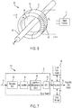
- FIG. 6 is a schematic diagram of injection transformer 50 shown in FIG. 5 . Shown in FIG. 6 are first power lead 16, injection transformer 50, toroid core 52, toroid center region 54, toroid split 56, primary windings 60 having a number N P of primary turns, and signal generator 70.
- Toroid core 52 defines toroid center region 54, thereby providing for the passage of first power lead 16.
- toroid core 52 has toroid split 56, thereby allowing toroid core 52 to be opened and/or separated into two halves, which can be beneficial in fabricating injection transformer 50 on first power lead 16 of an existing installation of heater 20.
- toroid split 56 can be omitted from toroid core 52.
- First power lead 16 can be described as passing through toroid center region 54, as shown in FIG.
- toroid core 52 is an iron core transformer.
- toroid core 52 is a ferrite core, made from a material that has a relatively high value of magnetic permeability, as may be commonly used in the electrical art as a transformer core.
- Toroid core 52 can be referred to as a circular transformer core.
- toroid core can be made from other materials that are capable of providing mutual inductive coupling, as will be described.
- the number of turns of the primary (N P ) and secondary (N S ) winding on toroid core 52, and the electrical wire thickness and insulation, are designed according to the current transformer known design principles.
- number of primary turns N P illustrated is reduced for simplicity.
- the number of primary turns N P can range from about 2,000 - 3,000.
- the number of primary turns Np can range from about 500 - 6,000.
- the number of primary turns N P can be fewer than 500 or greater than 6,000.
- alternating current flowing in a conductor passing through a ferrite core induces an alternating magnetic flux ⁇ (not labeled), thereby creating an alternating magnetic field B, which induces an alternating current in first power lead 16.
- the alternating magnetic field B can be annotated with a vector symbol, as shown in FIG. 6 .
- injected signal 72 is superimposed on the voltage waveform being supplied to heater 20.
- a fixture assembly (not shown) can be used to support injection transformer 50 and the various components thereof.
- a fixture assembly can also be referred to as a clamp assembly, and can provide a housing and hinge assembly (not shown) that can be used to open and close toroid core 52 relative to toroid split 54, thereby facilitating the installation and/or removal of injection transformer on first power lead 16.
- Other embodiments of injection transformer 50 will be shown and described later, in FIGS. 8 - 9 .
- FIG. 7 is a schematic diagram of a capacitive heater health monitoring system. Shown in FIG. 7 are diagnostic signal 78, signal reader 80, bandpass filter 82, amplifier 84, capacitance measurement circuit 86, analog-to-digital converter (ADC) 88, heater capacitance signal 90, processor 92, aircraft data system 94, data storage 96, prognostic data output 98, and heater health monitoring system 100. Diagnostic signal 78 is received from first power lead 16, as shown in FIG. 5 .
- signal reader 80 includes bandpass filter 82, amplifier 84, capacitance measurement circuit 86, ADC 88.
- Bandpass filter 82 is configured to pass a center frequency f c that corresponds to the frequency of injected frequency 72 from signal generator 70, thereby removing undesired signal components from diagnostic signal 78.
- undesired signal components include the fundamental frequency of heater power supply 13 and the harmonics thereof, electromagnetic interference (EMI), switching transients, DC voltage levels, and harmonics of injected frequency 72.
- center frequency f c and injected frequency 72 are both 10 KHz.
- bandpass filter 82 has a bandwidth of ⁇ 10% of f c (i.e., ⁇ 1 KHz at the -3 dB roll-off points). The bandwidth of bandpass filter 82 can be different in other embodiments.
- Amplifier 84 amplifies the signal level of diagnostic signal 78 after passing through bandpass filter 82, which is then provided to capacitance measurement circuit 86 which measures the capacitive reactance of heater 20, thereby producing a signal that is representative of heater capacitance C H as determined from the interaction of injected frequency 72 on heater 20, thereby producing diagnostic signal 78.
- the measurement of in-circuit electrical capacitance based on capacitive reactance is known to those who are skilled in the electrical art.
- bandpass filter 82, amplifier 84, and capacitance measurement circuit 86 are all analog circuits.
- ADC 88 produces heater capacitance signal 90 as being a digital representation of heater capacitance C H .
- bandpass filter 82, amplifier 84, and/or capacitance measurement circuit 86 can be a digital circuit. In these or other embodiments, bandpass filter 82 and/or amplifier 84 can be omitted from signal reader 80.
- heater capacitance signal 90 is provided to processor 92.
- processor 92 is a digital processor that receives, stores, scales, and processes heater capacitance signal 90.
- Processor 92 can also be referred to as a prognostic processor.
- Processor 92 can receive and process heater capacitance signal 90 continuously or periodically.
- processor 92 can include one or more processors (not shown in FIG. 7 ) that are configured to implement functionality and/or process instructions for execution within processor 92.
- the one or more processor(s) can be capable of processing instructions stored in one or more storage device(s), which can include data storage 96.
- processor(s) can include any one or more of a microprocessor, a controller, a digital signal processor (DSP), an application specific integrated circuit (ASIC), a field-programmable gate array (FPGA), or other equivalent discrete or integrated logic circuitry.
- Processor 92 produces prognostic data output 98, which can include the measured value of heater capacitance C H .
- processor 92 can receive multiple inputs corresponding to digitized heater capacitance signals 90 from multiple associated heaters 20.
- processor 92 can receive other inputs associated with heater 20 and/or with aircraft 10.
- processor 92 can exchange data with aircraft data system 94.
- processor 92 can also receive and process data from sources other than heater capacitance signal 90.
- processor 92 can receive data associated with a measured value of heater capacitance C H in heater 20. Moreover, in some embodiments, processor 92 can receive data from other aircraft data sources. In some embodiments, processor 92 can utilize data and signal analysis processing techniques on digitized heater capacitance signal(s) 90. In these or other embodiments, processor 92 can be a neural network. In some embodiments, processor 92 can provide information regarding one or more heaters 20 including the present value of heater capacitance C H , the history of heater capacitance C H over time (e.g., operating time or calendar time), the service life of heater 20 (i.e., operating time), the expected end-of-life (EOL), and the calculated remaining useful life (RUL).
- processor 92 can provide information regarding one or more heaters 20 including the present value of heater capacitance C H , the history of heater capacitance C H over time (e.g., operating time or calendar time), the service life of heater 20 (i.e., operating time), the expected end-of-life (
- prognostic data output 98 can be included in prognostic data output 98, and/or be provided to other systems (e.g., aircraft data system 94) for use by crew members.
- processor 92 can provide prognostic data output 98 data that can be transmitted and/or downloaded to engineering teams at an airline's operator, maintenance facility, and/or the various component suppliers whereby the data can be reviewed, analyzed, and/or archived.
- heater 20 is subject to different failure mechanisms, as described above in regard to FIG. 3 .
- Changes in heater capacitance C H can be used to predict feature failure before it occurs.
- changes in heater capacitance C H can be detected before changes in heater leakage current (I L ) can be detected.
- heater health monitoring system 100 can be beneficial in predicting a failure of heater 20 before another indication of heater failure occurs.
- An example of another indication of heater failure can be an increase in heater leakage current (I L ), which can be detected by a heater leakage current measurement system (not shown).
- a change in heater capacitance C H in either direction can provide an indication of heater degradation.
- processor 92 i.e., prognostic processor
- processor 92 can be configured to identify the nature of the degradation based on the change and/or the rate of change of heater capacitance C H .
- processor 92 can correlate changes in heater capacitance C H with other operating parameters as may be provided by aircraft data system 94 to identify the nature of the degradation in heater 20.
- heater health monitoring system 100 can track the health of each heater 20 in the system, allowing maintenance personnel to predict when failure is likely to occur so that maintenance can be scheduled prior to the point of expected failure for any particular heater 20. This can avoid flight delays that could ground an aircraft for emergent maintenance requirements, and it can also help prevent the in-flight failure of a particular heater 20 that could be disruptive to the performance of an associated air data probe 12.
- the exemplary embodiment of capacitance measurement system 40 and associated heater health monitoring system 100 is on heater 20 as used on an air data probe 12 (e.g., as on aircraft 10 shown in FIG. 1 ).
- the scope of the present disclosure includes the usage of health monitoring system 40 on any electrical heater, without regard to voltage, frequency, and/or power, regardless of location.
- electrical power that can be supplied from heater power supply 13 include AC frequencies of 50 Hz and 60 Hz, and also direct current (DC) voltage.
- Non-limiting examples of voltages that can be supplied from heater power supply 13 include 28 VDC, 115 VAC, 120 VAC, 200 VAC, 220 VAC, and 240 VAC. All voltages and frequencies (i.e., DC, or AC of any frequency) are within the scope of the present disclosure.
- heater health monitoring system 100 can be used on one or more heaters 20 that are located or installed in any vehicle, building, or other location, regardless of the electrical power characteristics of heater power supply 13.
- Non-limiting examples of other types of heaters include wing ice protection heaters, water heaters, and floor heaters.
- the scope of the present disclosure also includes insulation health monitoring on other electrical systems including, for example, cables, motors, and transformers.
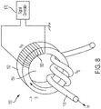
- FIG. 8 is a schematic diagram of a second embodiment of the injection transformer shown in FIG. 5 . Shown in FIG. 8 are first power lead 116, injection transformer 150, toroid core 152, toroid center region 154, primary windings 160 having N P primary turns, and signal generator 170, all having descriptions substantially similar to those provided above in regard to FIG. 6 .
- first power lead 116 passes through (i.e., traverses) toroid center region 154 three times. Accordingly, the number of secondary turns Ns can be said to be three, and the amplitude of the injected signal (not labeled in FIG. 8 ) is about three times as great as that provided in injection transformer 50 shown and described above in regard to FIG.
- toroid core 152 was used as a magnetic core, but non-toroid shapes are within the scope of the present disclosure. Non-limiting exemplary non-toroid shapes include oval, elliptical, hexagonal, pentagonal, square, and rectangular. Moreover, magnetic cores having geometric shapes that involve more than a single opening (i.e., single magnetic flux circuit) can also be used, with non-limiting examples including E-cores and EI-cores.
- FIG. 9 is a schematic diagram of a third embodiment of the injection transformer shown in FIG. 5 . Shown in FIG. 9 are first power lead 216, injection transformer 250, E-core 252, center regions 254A, 254B, I-core 255, primary windings 260A, 260B having N P1 , N P2 primary turns respectively, and signal generator 270. E-core 252 and I-core 255, when joined together as shown in FIG. 9 form an EI-core transformer that defines center regions 254A, 254B through which first power lead 216 passes one or more times.
- an advantage of using an EI-core for differential current detector 450 is the relative ease of separating and/or joining E-core 452 and I-core 455, which can be beneficial in installing injection transformer 250 on an existing first power lead 216.
- the EI-core injection transformer 250 shown in FIG. 9 can be used in some embodiments to provide a compact design instead of using a toroid core as shown in FIGS. 6 and 8 .
- injection transformer 50, 150, 250 shown and described above are exemplary, and can vary in different embodiments.
- a ferromagnetic material was shown for the magnetic core.
- An advantage of using a ferromagnetic core is that a relatively large mutual inductive coupling can be provided between the primary windings and the one or more secondary windings in a relatively small volume.
- a ferromagnetic core adds mass to a system, and can also be subject to magnetic saturation.
- injection transformer 50 can use a non-ferromagnetic core, with an air core transformer being an exemplary embodiment.
- An exemplary air core transformer is a Rogowski coil.
- a system for monitoring a health of a heater connected to a power supply by a first power lead conducting an inlet current and a second power lead conducting an outlet current comprising: an injection transformer, comprising a plurality of primary turns that are inductively coupled to the first power lead; a signal generator, configured to: generate a time-varying injection signal; and supply the time-varying injection signal to the plurality of primary turns, thereby impressing the time-varying injection signal on the inlet current; and a signal reader, configured to: receive a diagnostic signal from the heater; filter the diagnostic signal to pass a frequency associated with the time-varying injection signal; and produce a heater capacitance signal that is indicative of a capacitance value of the heater; wherein: the heater capacitance signal is indicative of the health of the heater.
- the system of the preceding paragraph can optionally include, additionally and/or alternatively, any one or more of the following features, configurations and/or additional components:
- the injection transformer comprises a ferromagnetic core configured to produce a mutual inductive coupling between the plurality of primary turns and the first power lead.
- the injection transformer comprises a toroid core defining a center region; the plurality of primary windings are wound around the toroid core; and the first power lead is configured to pass through the center region one or more times.
- the signal reader comprises: a band pass filter, configured to pass the frequency associated with the time-varying injection signal while attenuating frequencies less than and greater than the frequency associated with the time-varying injection signal; and a capacitance measurement circuit configured to produce the heater capacitance signal in response to a capacitive reactance of the heater; and wherein: the heater comprises: a resistive heating element; electrical insulation surrounding the resistive heating element; and a metallic sheath surrounding the electrical insulation; and the capacitive reactance depends at least in part on a condition of the electrical insulation.
- the signal reader further comprises an amplifier, configured to: amplify the frequency associated with the time-varying injection signal; and provide the amplified frequency associated with the time-varying injection signal to the capacitance measurement circuit.
- the signal reader further comprises an analog-to-digital converter (ADC), configured to convert the heater capacitance signal to a digitized heater capacitance signal.
- ADC analog-to-digital converter
- a further embodiment of the foregoing system further comprising a processor, configured to: receive the digitized heater capacitance signal; and produce a prognostic data output representative of the heater health.
- the primary winding comprises a number of primary turns that range from 500 - 6,000.
- the primary winding comprises a number of primary turns that range from 2,000 - 3,000.
- time-varying injection signal comprises a frequency that ranges from 5-25 KHz.
- injection transformer comprises a square core or an El-core.
- injection transformer comprises an air core
- a method of monitoring a health of a heater connected to a power supply by a first power lead conducting an inlet current and a second power lead conducting an outlet current comprising: generating, with a signal generator, a time-varying injection signal; supplying, to an injection transformer comprising a plurality of primary turns that are inductively coupled to the first power lead, the time-varying injection signal; receiving, by a signal reader, a diagnostic signal from the heater; passing, by the signal reader, a frequency associated with the time-varying injection signal; and producing, by the signal reader, a heater capacitance signal that is indicative of a capacitance value of the heater; wherein: the heater capacitance signal is indicative of the health of the heater.
- the method of the preceding paragraph can optionally include, additionally and/or alternatively, any one or more of the following features, configurations and/or additional components:
- the injection transformer comprises a ferromagnetic core configured to produce a mutual inductive coupling between the plurality of primary turns and the first power lead.
- the injection transformer comprises a toroid core defining a center region; the plurality of primary windings are wound around the toroid core; and the first power lead is configured to pass through the center region one or more times.
- the heater comprises a resistive heating element, electrical insulation surrounding the resistive heating element, and a metallic sheath surrounding the electrical insulation
- the method further comprises: passing, by a band pass filter, the frequency associated with the time-varying injection signal while attenuating frequencies less than and greater than the frequency associated with the time-varying injection signal; and producing, by a capacitance measurement circuit, the heater capacitance signal in response to a capacitive reactance of the heater that depends at least in part on a condition for the electrical insulation.
- a further embodiment of the foregoing method further comprising converting, by an analog-to-digital converter (ADC), the heater capacitance signal into a digitized heater capacitance signal.
- ADC analog-to-digital converter
- the primary winding comprises a number of primary turns that range from 500 - 6,000.
- time-varying injection signal comprises a frequency that ranges from 5-25 KHz.
- a further embodiment of the foregoing method further comprising: receiving, by a processor, the digitized heater capacitance signal; and producing, by the processor, a prognostic data output representative of the heater health.
Landscapes
- Physics & Mathematics (AREA)
- General Physics & Mathematics (AREA)
- Engineering & Computer Science (AREA)
- Aviation & Aerospace Engineering (AREA)
- Manufacturing & Machinery (AREA)
- Transportation (AREA)
- Investigating Or Analyzing Materials By The Use Of Electric Means (AREA)
Applications Claiming Priority (1)
| Application Number | Priority Date | Filing Date | Title |
|---|---|---|---|
| IN202041017303 | 2020-04-22 |
Publications (2)
| Publication Number | Publication Date |
|---|---|
| EP3901636A1 true EP3901636A1 (fr) | 2021-10-27 |
| EP3901636B1 EP3901636B1 (fr) | 2024-03-13 |
Family
ID=75659786
Family Applications (1)
| Application Number | Title | Priority Date | Filing Date |
|---|---|---|---|
| EP21169946.7A Active EP3901636B1 (fr) | 2020-04-22 | 2021-04-22 | Surveillance pronostique de l'état d'un dispositif de chauffage |
Country Status (2)
| Country | Link |
|---|---|
| US (1) | US11630140B2 (fr) |
| EP (1) | EP3901636B1 (fr) |
Families Citing this family (3)
| Publication number | Priority date | Publication date | Assignee | Title |
|---|---|---|---|---|
| US11867746B2 (en) * | 2021-09-14 | 2024-01-09 | Hamilton Sundstrand Corporation | Failure detection system for integrated circuit components |
| US12405330B2 (en) * | 2023-10-06 | 2025-09-02 | GE Precision Healthcare LLC | Ceramic toroidal cable trap |
| US20250361024A1 (en) * | 2024-05-23 | 2025-11-27 | Rosemount Aerospace Inc. | PROGNOSTIC HEALTH MONITOR FOR AIRCRAFT-BASED ANALOG ANGLE OF ATTACK (AoA) SENSORS |
Citations (4)
| Publication number | Priority date | Publication date | Assignee | Title |
|---|---|---|---|---|
| US20130037535A1 (en) * | 2010-06-10 | 2013-02-14 | Panasonic Corporation | Induction cooker |
| US20140103938A1 (en) * | 2012-10-12 | 2014-04-17 | Msx, Incorporated | Self-regulating heater cable fault detector |
| EP3379265A1 (fr) * | 2017-03-24 | 2018-09-26 | Rosemount Aerospace Inc. | Détermination de la durée de vie utile restante d'un réchauffeur de sonde |
| EP3745141A1 (fr) * | 2019-05-29 | 2020-12-02 | Rosemount Aerospace Inc. | Mesure du courant de fuite différentiel pour la surveillance de l'état d'un dispositif de chauffage |
Family Cites Families (170)
| Publication number | Priority date | Publication date | Assignee | Title |
|---|---|---|---|---|
| GB809608A (en) | 1955-04-22 | 1959-02-25 | Curtiss Wright Corp | Improved aircraft static pressure simulating system |
| GB884415A (en) | 1958-11-10 | 1961-12-13 | Kyowa Hakko Kogyo Kk | Method for producing l-pyrrolidonecarboxylic acid and its salts |
| GB1293589A (en) | 1968-11-14 | 1972-10-18 | Asahi Chemical Ind | Rubbery copolymer compositions |
| US3798652A (en) | 1972-09-11 | 1974-03-19 | Gen Electric | Pitot tube dielectric antenna system |
| US4121088A (en) | 1976-10-18 | 1978-10-17 | Rosemount Inc. | Electrically heated air data sensing device |
| US4207566A (en) | 1978-05-05 | 1980-06-10 | American Aerospace Controls, Inc. | DC Current level detector for monitoring a pitot tube heater and associated method |
| US4267721A (en) | 1979-11-09 | 1981-05-19 | Timeter Instrument Corp. | Respiratory analyzer |
| US4506259A (en) | 1981-11-24 | 1985-03-19 | Raychem Corporation | Digital fault monitor for conductive heaters |
| US4698583A (en) | 1985-03-26 | 1987-10-06 | Raychem Corporation | Method of monitoring a heater for faults |
| CA1311028C (fr) | 1988-05-20 | 1992-12-01 | Westinghouse Electric Corporation | Instrumentation et systemes de surveillance faisant appel a la temperature differentielle |
| JP2681673B2 (ja) | 1988-11-30 | 1997-11-26 | 原電子測器株式会社 | 平面探傷用交流漏洩磁束探傷装置 |
| GB8906885D0 (en) | 1989-03-28 | 1989-05-10 | Raychem Ltd | Monitoring electric cables |
| CA2049616C (fr) | 1991-01-22 | 2000-04-04 | Jacob Soiferman | Methode de verification sans contact et systeme de verification de cartes de circuits integres |
| JP2636527B2 (ja) | 1991-03-04 | 1997-07-30 | 三菱電機株式会社 | 電気機器収納装置の絶縁劣化防止及び絶縁劣化予測診断装置 |
| US5464965A (en) | 1993-04-20 | 1995-11-07 | Honeywell Inc. | Apparatus for controlling temperature of an element having a temperature variable resistance |
| JPH0720577U (ja) | 1993-09-20 | 1995-04-11 | 株式会社ムサシ電機計器製作所 | 漏洩電流測定装置 |
| GB9422714D0 (en) | 1994-11-10 | 1995-01-04 | Powerbreaker Plc | Current transducers |
| US6151560A (en) | 1995-03-27 | 2000-11-21 | Jones; Thaddeus M. | Open circuit failure monitoring apparatus for controlled electrical resistance heaters |
| US5767781A (en) | 1995-06-15 | 1998-06-16 | Applied Materials, Inc. | Method for detection of failed heater in a daisy chain connection |
| DE19546788A1 (de) | 1995-12-14 | 1997-06-19 | Siemens Ag | Verfahren zur Verbesserung der Fehlererkennung bei einer Wirbelstrom-Integritätsprüfung und zur Erhaltung der Wärmeübertragungskapazität von Wärmetauscherrohren |
| JP2001505659A (ja) | 1996-10-16 | 2001-04-24 | ローズマウント・エアロスペース・インコーポレーテッド | 加熱式空気データプローブ |
| CA2242500C (fr) | 1997-09-15 | 2007-11-13 | Monarch Marking Systems, Inc. | Circuit de predetection de pannes de tetes d'impression |
| US6070475A (en) | 1997-10-15 | 2000-06-06 | Rosemont Aerospace Inc. | Air data probe with heater means within wall |
| US6107611A (en) | 1998-01-19 | 2000-08-22 | Msx, Inc. | Method and apparatus for detecting ground faults in a shielded heater wire by sensing electrical arcing |
| US6218647B1 (en) | 1998-01-19 | 2001-04-17 | Msx, Inc. | Method and apparatus for using direct current to detect ground faults in a shielded heater wire |
| US5986860A (en) | 1998-02-19 | 1999-11-16 | Square D Company | Zone arc fault detection |
| US6266219B1 (en) * | 1998-06-02 | 2001-07-24 | Pass & Seymour, Inc. | Combination ground fault and arc fault circuit interrupter |
| DE19833454C2 (de) | 1998-07-24 | 2000-06-08 | Siemens Ag | Verfahren zur Verringerung von Driftverhalten bei resistiven Hochtemperatur-Gassensoren und Vorrichtung zur Durchführung des Verfahrens |
| US6300767B1 (en) | 1998-11-30 | 2001-10-09 | General Electric Company | System and apparatus for predicting failure in insulated systems |
| US7034660B2 (en) | 1999-02-26 | 2006-04-25 | Sri International | Sensor devices for structural health monitoring |
| US6336083B1 (en) | 1999-05-21 | 2002-01-01 | Watlow Electric Manufacturing Company | Method and apparatus for predicting heater failure |
| US6270460B1 (en) | 1999-06-24 | 2001-08-07 | Acuson Corporation | Apparatus and method to limit the life span of a diagnostic medical ultrasound probe |
| US6414508B1 (en) | 1999-06-28 | 2002-07-02 | Adaptec, Inc. | Methods for predicting reliability of semiconductor devices using voltage stressing |
| DE10033336A1 (de) | 1999-08-11 | 2001-04-12 | Heinz Lindenmeier | Diversityantenne für eine Diversityantennenanlage in einem Fahrzeug |
| US6388237B1 (en) | 1999-08-19 | 2002-05-14 | Totoku Electric Co., Ltd. | Heater cable in combination with a lead cable |
| US6430996B1 (en) | 1999-11-09 | 2002-08-13 | Mark Anderson | Probe and integrated ice detection and air data system |
| JP3553439B2 (ja) | 1999-11-16 | 2004-08-11 | 三菱重工業株式会社 | 亀裂モニタリング方法および亀裂モニタリング装置 |
| US6414282B1 (en) | 2000-11-01 | 2002-07-02 | Rosemount Aerospace Inc. | Active heater control circuit and method used for aerospace probes |
| US6490927B2 (en) | 2000-12-22 | 2002-12-10 | Honeywell International Inc. | Method for detecting multiple types of corrosion |
| JP2003215081A (ja) | 2002-01-24 | 2003-07-30 | Central Glass Co Ltd | 板ガラスに形成された導電線の断線検査方法およびその装置 |
| US6570373B1 (en) | 2002-03-07 | 2003-05-27 | Visteon Global Technologies, Inc. | Current sensor programmable through connector |
| US6930610B2 (en) | 2002-05-03 | 2005-08-16 | General Electric Company | Monitoring system and method for wiring systems |
| KR100750546B1 (ko) | 2002-06-26 | 2007-08-20 | 미쯔이 죠센 가부시키가이샤 | 유도 가열 방법 및 장치 |
| US6956489B2 (en) | 2002-07-17 | 2005-10-18 | Mrl Industries | Heating element condition monitor |
| US6906537B2 (en) | 2002-08-19 | 2005-06-14 | Hamilton Sundstrand | System for controlling the temperature of an aircraft airfoil component |
| GB2396015A (en) | 2002-12-06 | 2004-06-09 | Automotive Electronics Ltd Ab | Moderating the output of a capacitive sensor |
| FR2850495B1 (fr) | 2003-01-24 | 2005-06-03 | Schneider Electric Ind Sas | Dispositif de protection differentielle et appareil de coupure electrique comportant un tel dispositif |
| US6881932B2 (en) | 2003-04-29 | 2005-04-19 | Harco Laboratories, Inc. | High reliability heater modules |
| US7243317B2 (en) | 2003-05-30 | 2007-07-10 | Illinios Institute Of Technology | Parameter checking method for on-chip ESD protection circuit physical design layout verification |
| DE60329634D1 (de) | 2003-08-20 | 2009-11-19 | Boeing Co | Verfahren und systeme zur erkennung von vereisungsbedingungen |
| FR2859787B1 (fr) | 2003-09-16 | 2006-01-20 | Thales Sa | Dispositif et procede de determination de la temperature totale pour aeronef |
| JP4368704B2 (ja) | 2004-03-12 | 2009-11-18 | 三井金属鉱業株式会社 | 電子部品実装用プリント配線板の電気検査方法および電気検査装置ならびにコンピュータ読み取り可能な記録媒体 |
| US6974250B2 (en) | 2004-04-15 | 2005-12-13 | Rosemount Aerospace Inc. | Temperature sensor with controlled thermal offset for determining static temperature |
| US20050231153A1 (en) | 2004-04-20 | 2005-10-20 | Scott Dewey | High voltage isolation detection of a fuel cell system using magnetic field cancellation |
| FR2872913B1 (fr) | 2004-07-06 | 2006-10-27 | Chauvin Arnoux | Procede de determination des composantes active et reactive de l'impedance de boucle d'un reseau d'alimentation en courant alternatif, ainsi qu'un dispositif pour la mise en oeuvre de ce procede |
| US7157920B2 (en) | 2004-08-10 | 2007-01-02 | United Technologies Corporation | Non-destructive monitoring of material integrity |
| JP4670291B2 (ja) | 2004-09-21 | 2011-04-13 | 富士ゼロックス株式会社 | インクジェット記録ヘッド故障予測システム |
| US7241974B2 (en) | 2004-11-08 | 2007-07-10 | Allied Precision Industries, Inc. | System and method of deactivating a fluid receptacle deicer |
| DE102004056436B4 (de) | 2004-11-19 | 2019-04-04 | Jenoptik Advanced Systems Gmbh | Verfahren und Vorrichtung zur Erkennung von Fehlerstrom-Lichtbögen in elektrischen Stromkreisen |
| JP2008530497A (ja) | 2005-02-15 | 2008-08-07 | コントロール・デヴァイシス・インコーポレーテッド | 氷を検出し製造するための方法および装置 |
| JP4871522B2 (ja) | 2005-04-04 | 2012-02-08 | パナソニック株式会社 | 高周波誘電加熱用電力制御方法及びその装置 |
| NO323931B1 (no) | 2005-04-05 | 2007-07-23 | Harald Horn | Maling av tilstanden i stalstrukturer ved patrykk av en pulsformet elektrisk strom og analyse av spenningsfallet |
| RU2290646C1 (ru) | 2005-08-26 | 2006-12-27 | Федеральное государственное унитарное предприятие "Центральный аэрогидродинамический институт им. проф. Н.Е. Жуковского" (ФГУП "ЦАГИ") | Система измерения воздушных параметров полета |
| DE102005044831A1 (de) | 2005-09-20 | 2007-03-22 | Siemens Ag | Verfahren und Vorrichtung zur Überwachung einer elektrischen Heizung |
| JP4748356B2 (ja) | 2005-10-13 | 2011-08-17 | サンケン電気株式会社 | 誘導加熱装置 |
| US7490510B2 (en) | 2005-10-24 | 2009-02-17 | Ametek, Inc. | Multi-function air data sensor |
| EP1783228A1 (fr) | 2005-11-08 | 2007-05-09 | ETH Zürich | Expression recombinante de complexes multiprotéiques en utilisant des polygènes |
| US7256372B2 (en) * | 2005-12-07 | 2007-08-14 | Aos Holding Company | Fluid-heating apparatus, circuit for heating a fluid, and method of operating the same |
| US7209651B1 (en) | 2005-12-07 | 2007-04-24 | Aos Holding Company | Fluid-heating apparatus, circuit for heating a fluid, and method of operating the same |
| US7193428B1 (en) | 2006-01-19 | 2007-03-20 | Veris Industries, Llc | Low threshold current switch |
| FR2897197B1 (fr) | 2006-02-03 | 2008-04-18 | Univ Aix Marseill Iii Paul Cezanne | Source lumineuse etendue et electriquement modulable, dispositif de mesure pour caracteriser un semi-conducteur comportant une telle source |
| US20070208520A1 (en) | 2006-03-01 | 2007-09-06 | Siemens Energy & Automation, Inc. | Systems, devices, and methods for arc fault management |
| US8182143B2 (en) | 2006-08-09 | 2012-05-22 | Spectrasensors, Inc. | Mobile temperature sensor |
| US7418878B2 (en) | 2006-09-19 | 2008-09-02 | Los Robles Advertising, Inc. | Universal sensor controller for a thermal anemometer |
| TW200821609A (en) | 2006-11-10 | 2008-05-16 | Prodigit Electronics Co Ltd | Digital electric leakage detection monitoring device |
| EP1936367A1 (fr) | 2006-12-22 | 2008-06-25 | Mettler-Toledo AG | Procédé et dispositif destinés à la surveillance et/ou la détermination de l'état d'une sonde de mesure |
| US20080183404A1 (en) | 2007-01-13 | 2008-07-31 | Arsalan Alan Emami | Monitoring heater condition to predict or detect failure of a heating element |
| US9147644B2 (en) | 2008-02-26 | 2015-09-29 | International Rectifier Corporation | Semiconductor device and passive component integration in a semiconductor package |
| US8531202B2 (en) | 2007-10-11 | 2013-09-10 | Veraconnex, Llc | Probe card test apparatus and method |
| FR2924498B1 (fr) | 2007-11-30 | 2009-12-11 | Thales Sa | Girouette de mesure de l'orientation du vent a rechauffeur integre |
| US8466390B2 (en) | 2008-01-08 | 2013-06-18 | Rosemount Aerospace Inc. | Heater control architecture for an ice protection system |
| US20110118990A1 (en) | 2008-05-27 | 2011-05-19 | Jagjit Sidhu | Damage sensors and processing arrangements therefor |
| US20090321415A1 (en) | 2008-06-25 | 2009-12-31 | Honeywell International Inc. | Flexible heater comprising a temperature sensor at least partially embedded within |
| EP2322945B1 (fr) | 2008-08-11 | 2014-11-26 | LG Chem, Ltd. | Appareil et procédé permettant la détection de courant de fuite de batteries, et appareil de commande de batteries et bloc de batteries comportant l'appareil |
| US9100994B2 (en) | 2008-10-14 | 2015-08-04 | Airbus Operations Gmbh | Heating system having at least one electrothermal heating layer, a structural component having such a heating layer, a heating method and a method for producing a semi-finished component or a component having a heating device |
| US8247747B2 (en) | 2008-10-30 | 2012-08-21 | Xaloy, Inc. | Plasticating barrel with integrated exterior heater layer |
| US9442019B2 (en) | 2008-12-26 | 2016-09-13 | Fluke Corporation | Infrared imaging probe |
| US8222912B2 (en) | 2009-03-12 | 2012-07-17 | Sv Probe Pte. Ltd. | Probe head structure for probe test cards |
| GB0914651D0 (en) | 2009-08-21 | 2009-09-30 | Pilkington Automotive D Gmbh | Heatable glazing inspection |
| US8305783B2 (en) | 2009-09-10 | 2012-11-06 | B/E Aerospace, Inc. | Systems and methods for polyphase alternating current transformer inrush current limiting |
| US20110089958A1 (en) | 2009-10-19 | 2011-04-21 | Applied Nanostructured Solutions, Llc | Damage-sensing composite structures |
| US8392141B2 (en) | 2009-11-02 | 2013-03-05 | Rosemount Aerospace Inc. | Total air temperature probe and method for reducing de-icing/anti-icing heater error |
| KR101110789B1 (ko) | 2010-04-09 | 2012-02-24 | 쿠쿠전자주식회사 | 유도 가열 조리기의 히터 불량 검출 장치 |
| JP5296739B2 (ja) | 2010-04-28 | 2013-09-25 | 浜松ホトニクス株式会社 | 半導体故障解析装置及び故障解析方法 |
| KR101173752B1 (ko) | 2010-05-11 | 2012-08-13 | 한국항공우주산업 주식회사 | 항공기의 열선장비 감시장치 |
| US9335299B2 (en) | 2010-06-23 | 2016-05-10 | Acousticeye Ltd | Method and system for testing a bundle of tubular objects guided by a computing device |
| KR101238664B1 (ko) | 2010-12-06 | 2013-03-04 | 한국세라믹기술원 | 석영관 히터의 신뢰성 평가 방법 |
| JP2012173183A (ja) | 2011-02-23 | 2012-09-10 | Hitachi Cable Ltd | ケーブル被覆材料の寿命検査方法 |
| JP5548640B2 (ja) | 2011-03-22 | 2014-07-16 | アズビル株式会社 | 湿度測定装置および劣化検査方法 |
| US10090777B2 (en) | 2011-05-08 | 2018-10-02 | Koolbridge Solar, Inc. | Inverter with independent current and voltage controlled outputs |
| CA2838558C (fr) | 2011-05-24 | 2022-08-30 | Fastcap Systems Corporation | Systeme d'alimentation comportant un stockage d'energie rechargeable pour des applications a haute temperature |
| US9068929B2 (en) | 2011-06-14 | 2015-06-30 | Aurora Flight Sciences Corporation | Capacitance-based system health monitoring system, apparatus and method for layered structure |
| US10163668B2 (en) | 2011-08-30 | 2018-12-25 | Watlow Electric Manufacturing Company | Thermal dynamic response sensing systems for heaters |
| KR101254293B1 (ko) | 2011-09-08 | 2013-04-12 | 이재준 | 스마트 기능을 보유한 지능형 히팅 케이블 및 그 제조방법 |
| US9080917B2 (en) | 2011-10-07 | 2015-07-14 | Shell Oil Company | System and methods for using dielectric properties of an insulated conductor in a subsurface formation to assess properties of the insulated conductor |
| US9046899B2 (en) | 2011-11-01 | 2015-06-02 | Goodrich Corporation | Aircraft heating system |
| CN103213543B (zh) | 2012-01-18 | 2015-11-25 | 比亚迪股份有限公司 | 一种电动车行车控制系统 |
| US20130194101A1 (en) | 2012-01-31 | 2013-08-01 | General Electric Company | System and method for health monitoring of power cables |
| BE1020543A3 (fr) | 2012-02-24 | 2013-12-03 | Sonaca Sa | Procede de fabrication d'une peau de bord d'attaque par cuisson d'un empilement integrant des elements chauffants et des couches de fibres preimpregnees. |
| WO2013135280A1 (fr) | 2012-03-14 | 2013-09-19 | Beurer Gmbh | Appareil de chauffage flexible |
| EP3855869A3 (fr) * | 2012-05-18 | 2021-10-27 | Neturen Co., Ltd. | Système de chauffage par induction, procédé de chauffage par induction, appareil de surveillance de sortie, procédé de surveillance de sortie et appareil de chauffage par induction |
| KR20130130529A (ko) | 2012-05-22 | 2013-12-02 | 조선대학교산학협력단 | 소구경 배관 결함 탐상 장치 및 방법 |
| US10270261B2 (en) | 2015-09-16 | 2019-04-23 | Energous Corporation | Systems and methods of object detection in wireless power charging systems |
| CN103577168A (zh) | 2012-07-27 | 2014-02-12 | 鸿富锦精密工业(深圳)有限公司 | 测试用例创建系统及方法 |
| CN102901445B (zh) | 2012-09-28 | 2015-06-10 | 华中科技大学 | 基于光热成像的微电子封装工艺质量检测装置及方法 |
| US8890703B2 (en) | 2013-02-06 | 2014-11-18 | General Electric Company | Passive water heater anode rod depletion sensor algorithm |
| FR3002801B1 (fr) | 2013-03-01 | 2015-03-20 | Thales Sa | Sonde de mesure de pression totale d'un ecoulement et procede de mise en oeuvre de la sonde |
| CA2904734C (fr) | 2013-03-15 | 2018-01-02 | Emerson Electric Co. | Diagnostic et systeme de telesurveillance de chauffage, de ventilation et de climatisation |
| CN105122046B (zh) | 2013-03-29 | 2018-01-23 | 斯奈克玛 | 用于检测物体上的缺陷方法 |
| FR3004547B1 (fr) | 2013-04-16 | 2015-05-01 | Airbus Operations Sas | Procede et dispositif de detection automatique d'une mesure erronee d'une temperature totale sur un aeronef. |
| GB201308397D0 (en) | 2013-05-10 | 2013-06-19 | Rolls Royce Plc | Equipment monitoring system |
| EP2829871A1 (fr) | 2013-07-26 | 2015-01-28 | Helmholtz Zentrum München Forschungszentrum für Gesundheit und Umwelt GmbH | Dispositif capteur et procédé de mesure thermoacoustique de champs électromagnétiques |
| KR101518374B1 (ko) | 2013-10-10 | 2015-05-07 | 이도형 | 박막의 계측시스템 및 그 방법 |
| CN105830548B (zh) | 2013-10-31 | 2017-12-01 | 阿莫绿色技术有限公司 | 散热部件及具有其的便携式终端 |
| CN105723196B (zh) | 2013-11-07 | 2021-01-26 | 滤波器感知技术有限公司 | 高级射频感测探针 |
| US9733201B2 (en) | 2013-11-15 | 2017-08-15 | Pentair Thermal Management Llc | Thermal age tracking system and method |
| US9417203B2 (en) | 2013-12-05 | 2016-08-16 | Bourns, Inc. | Conductive liquid property measurement using multiple charge transfer times |
| US9463879B2 (en) | 2014-03-03 | 2016-10-11 | The Boeing Company | Systems and methods for predicting and controlling ice formation |
| WO2015167623A2 (fr) | 2014-04-29 | 2015-11-05 | William Dean Wallace | Procédés de traitement et dispositifs chirurgicaux portatifs pour le traitement de cellules hyperplasiques et néoplasiques dans le col de l'utérus et autres troubles dermatologiques ou superficiels |
| EP3195406A1 (fr) | 2014-09-19 | 2017-07-26 | Pentair Thermal Management LLC | Système pour fonte de neige et de glace et capteurs associés |
| US9654054B1 (en) * | 2014-09-30 | 2017-05-16 | Technology For Energy Corporation | Device and method for saturation prevention by transfer function modulation associated with conditioning of electrical current or voltage |
| JP6478200B2 (ja) | 2014-10-17 | 2019-03-06 | 株式会社ケーヒン | 電源電圧検出装置 |
| US9927480B2 (en) | 2014-11-06 | 2018-03-27 | Rosemount Aerospace, Inc. | System and method for probe heater health indication |
| US10302312B2 (en) | 2014-12-22 | 2019-05-28 | Battelle Memorial Institute | Estimation of unknown states for an electric water heater with thermal stratification and use of same in demand response and condition-based maintenance |
| CA2919341C (fr) | 2015-04-02 | 2022-11-15 | Rosemount Aerospace, Inc. | Sonde de donnees aeriennes chauffee resistante a la corrosion |
| US20160313259A1 (en) | 2015-04-20 | 2016-10-27 | Vayyar Imaging Ltd. | Temperature compensated dielectric characterization of substances |
| US9842714B2 (en) | 2015-05-19 | 2017-12-12 | Haier Us Appliance Solutions, Inc. | Detecting current leakage in a heating element |
| US10118119B2 (en) | 2015-06-08 | 2018-11-06 | Cts Corporation | Radio frequency process sensing, control, and diagnostics network and system |
| US9971792B2 (en) | 2015-06-10 | 2018-05-15 | Flir Systems Ab | Image retrieval and processing systems and methods |
| US9970824B2 (en) | 2015-06-29 | 2018-05-15 | Pratt & Whitney Canada Corp. | Sensor probe with anti-icing |
| US9759759B2 (en) | 2015-07-15 | 2017-09-12 | Vale S.A. | Apparatus and method for sensing a leakage current between first and second locations in a single wire earth return circuit |
| CN105092050B (zh) | 2015-08-13 | 2018-06-19 | 国家电网公司 | 一种gis内部导体过热故障的检测方法及装置 |
| JP6686134B2 (ja) | 2015-10-01 | 2020-04-22 | ワトロー エレクトリック マニュファクチュアリング カンパニー | 加熱器の寿命及び性能を強化するための一体型装置及び方法 |
| US11047745B2 (en) | 2015-12-11 | 2021-06-29 | The Boeing Company | Lightweight fire detection systems and methods |
| US9885761B2 (en) | 2016-03-14 | 2018-02-06 | Rosemount Aerospace, Inc. | DC power heater short-to-chassis ground detection circuit |
| US20170259927A1 (en) | 2016-03-14 | 2017-09-14 | Rosemount Aerospace, Inc. | Ac power heater short-to-chassis ground detection circuit |
| US9939459B2 (en) | 2016-04-19 | 2018-04-10 | The Boeing Company | System and method for performing a test on a pitot probe heating element |
| GB2550395B (en) | 2016-05-19 | 2020-08-12 | Hs Marston Aerospace Ltd | Method and system for thermographic analysis |
| US20170343418A1 (en) | 2016-05-27 | 2017-11-30 | Erin Hurbi | Thermal camera calibration palette |
| US10375325B2 (en) | 2016-06-23 | 2019-08-06 | Fluke Corporation | Thermal anomaly detection |
| US10551220B2 (en) | 2016-06-27 | 2020-02-04 | Rolls-Royce Corporation | Capacitive measurement device |
| CA2964260C (fr) | 2016-06-28 | 2025-08-26 | Rosemount Aerospace Inc. | Sonde de detection de donnees de l'air au moyen d'un detecteur d'etat de givrage |
| US9919812B2 (en) | 2016-08-08 | 2018-03-20 | The Boeing Company | Early detection of faulty deicing heaters on wide-body aircraft |
| JP6227090B1 (ja) | 2016-10-27 | 2017-11-08 | 三菱電機株式会社 | 給電制御装置及び給電制御装置に対する制御特性の補正データ生成方法 |
| FR3061166B1 (fr) | 2016-12-22 | 2019-05-31 | Commissariat A L'energie Atomique Et Aux Energies Alternatives | Structure microelectronique comportant des moyens de controle de l'amortissement visqueux |
| US10180449B2 (en) * | 2017-03-24 | 2019-01-15 | Rosemount Aerospace Inc. | Probe heater remaining useful life determination |
| US10564203B2 (en) | 2017-03-24 | 2020-02-18 | Rosemount Aerospace Inc. | Probe heater remaining useful life determination |
| US10197517B2 (en) | 2017-03-24 | 2019-02-05 | Rosemount Aerospace, Inc. | Probe heater remaining useful life determination |
| US10151785B2 (en) | 2017-03-24 | 2018-12-11 | Rosemount Aerospace Inc. | Probe heater remaining useful life determination |
| US11060992B2 (en) | 2017-03-24 | 2021-07-13 | Rosemount Aerospace Inc. | Probe heater remaining useful life determination |
| US10914777B2 (en) | 2017-03-24 | 2021-02-09 | Rosemount Aerospace Inc. | Probe heater remaining useful life determination |
| US10583928B2 (en) | 2017-04-10 | 2020-03-10 | B/E Aerospace, Inc. | Inline heater controller |
| GB2561393B (en) | 2017-04-13 | 2019-12-04 | Gkn Aerospace Services Ltd | Electrothermal heater |
| US10716171B2 (en) | 2018-03-23 | 2020-07-14 | Rosemount Aerospace Inc. | Power efficient heater control of air data sensor |
| US11117670B2 (en) | 2018-06-19 | 2021-09-14 | The Boeing Company | Methods and apparatus to detect deicing heater conditions |
| US10816436B2 (en) | 2018-07-06 | 2020-10-27 | The Boeing Company | System for temperature insensitive damage detection |
| CN109246868A (zh) | 2018-07-23 | 2019-01-18 | 合肥暖心电器有限公司 | 一种具有漏电保护功能的电热毯 |
| CN109521252A (zh) | 2018-11-27 | 2019-03-26 | 北京智芯微电子科技有限公司 | 直流漏电流的检测装置 |
| US11061080B2 (en) | 2018-12-14 | 2021-07-13 | Rosemount Aerospace Inc. | Real time operational leakage current measurement for probe heater PHM and prediction of remaining useful life |
| US11472562B2 (en) | 2019-06-14 | 2022-10-18 | Rosemount Aerospace Inc. | Health monitoring of an electrical heater of an air data probe |
-
2020
- 2020-06-30 US US16/946,652 patent/US11630140B2/en active Active
-
2021
- 2021-04-22 EP EP21169946.7A patent/EP3901636B1/fr active Active
Patent Citations (4)
| Publication number | Priority date | Publication date | Assignee | Title |
|---|---|---|---|---|
| US20130037535A1 (en) * | 2010-06-10 | 2013-02-14 | Panasonic Corporation | Induction cooker |
| US20140103938A1 (en) * | 2012-10-12 | 2014-04-17 | Msx, Incorporated | Self-regulating heater cable fault detector |
| EP3379265A1 (fr) * | 2017-03-24 | 2018-09-26 | Rosemount Aerospace Inc. | Détermination de la durée de vie utile restante d'un réchauffeur de sonde |
| EP3745141A1 (fr) * | 2019-05-29 | 2020-12-02 | Rosemount Aerospace Inc. | Mesure du courant de fuite différentiel pour la surveillance de l'état d'un dispositif de chauffage |
Also Published As
| Publication number | Publication date |
|---|---|
| EP3901636B1 (fr) | 2024-03-13 |
| US11630140B2 (en) | 2023-04-18 |
| US20210364561A1 (en) | 2021-11-25 |
Similar Documents
| Publication | Publication Date | Title |
|---|---|---|
| US11639954B2 (en) | Differential leakage current measurement for heater health monitoring | |
| EP3751292B1 (fr) | Surveillance de l'état de santé d'un chauffage électrique d'une sonde de données d'air | |
| EP3901636B1 (fr) | Surveillance pronostique de l'état d'un dispositif de chauffage | |
| US11293995B2 (en) | Differential leakage current measurement for heater health monitoring | |
| CN107703379B (zh) | 用于监控飞机上的关键部件的系统以及方法 | |
| CN111323680B (zh) | 用于检测电弧故障的方法和电路 | |
| US8773112B2 (en) | Current sensor | |
| US20150226772A1 (en) | Detection of geomagnetically-induced currents with power line-mounted devices | |
| US7145345B2 (en) | Current transformers for partial discharge detection on aircraft cables and wires | |
| JP2020093779A (ja) | 航空機用システム | |
| EP2360805B1 (fr) | Système de transmission d'alimentation électrique d'un véhicule | |
| JP2023536865A (ja) | 除氷システムと制御 | |
| SE515388C2 (sv) | Anordning för avkänning av elektriska urladdningar i ett provobjekt | |
| WO1997022884A9 (fr) | Detecteur de courant | |
| EP0868666A1 (fr) | Detecteur de courant | |
| CN112154585B (zh) | 用于识别并联布置的绕组中的匝间短路的方法和装置 | |
| US20170089986A1 (en) | Measuring Arrangement for Detecting a Magnetic Unidirectional Flux in the Core of a Transformer | |
| US20120062214A1 (en) | Contactless electrical connector for an induction sensor, and sensor including such a connector | |
| US20080088466A1 (en) | System and method to zero-sequence verify ground return path integrity by comparing measured zero-sequence current in an autotransformer with a second zero-sequence current source | |
| RU2844196C1 (ru) | Противообледенительные системы и управление ими | |
| US12306268B2 (en) | Health monitoring in electric motor control systems | |
| CN114200252B (zh) | 一种电缆故障的检测装置 | |
| BR102019026487B1 (pt) | Sistema para monitorar a integridade de um aquecedor elétrico de uma sonda de dados aéreos | |
| Risse et al. | Wendelstein 7-X trim coils—Component safety aspects and commissioning strategy | |
| Robles Muñoz et al. | High-Frequency Current Transformer Design to Detect Serial Arcs in More Electric Aircraft |
Legal Events
| Date | Code | Title | Description |
|---|---|---|---|
| PUAI | Public reference made under article 153(3) epc to a published international application that has entered the european phase |
Free format text: ORIGINAL CODE: 0009012 |
|
| STAA | Information on the status of an ep patent application or granted ep patent |
Free format text: STATUS: THE APPLICATION HAS BEEN PUBLISHED |
|
| AK | Designated contracting states |
Kind code of ref document: A1 Designated state(s): AL AT BE BG CH CY CZ DE DK EE ES FI FR GB GR HR HU IE IS IT LI LT LU LV MC MK MT NL NO PL PT RO RS SE SI SK SM TR |
|
| B565 | Issuance of search results under rule 164(2) epc |
Effective date: 20210901 |
|
| STAA | Information on the status of an ep patent application or granted ep patent |
Free format text: STATUS: REQUEST FOR EXAMINATION WAS MADE |
|
| 17P | Request for examination filed |
Effective date: 20220427 |
|
| RBV | Designated contracting states (corrected) |
Designated state(s): AL AT BE BG CH CY CZ DE DK EE ES FI FR GB GR HR HU IE IS IT LI LT LU LV MC MK MT NL NO PL PT RO RS SE SI SK SM TR |
|
| RAP1 | Party data changed (applicant data changed or rights of an application transferred) |
Owner name: ROSEMOUNT AEROSPACE INC. |
|
| GRAP | Despatch of communication of intention to grant a patent |
Free format text: ORIGINAL CODE: EPIDOSNIGR1 |
|
| STAA | Information on the status of an ep patent application or granted ep patent |
Free format text: STATUS: GRANT OF PATENT IS INTENDED |
|
| RIC1 | Information provided on ipc code assigned before grant |
Ipc: G01R 31/00 20060101ALN20231011BHEP Ipc: B64D 15/12 20060101ALN20231011BHEP Ipc: B64D 43/02 20060101ALN20231011BHEP Ipc: G01R 27/26 20060101ALI20231011BHEP Ipc: B64D 45/00 20060101ALI20231011BHEP Ipc: H05B 1/02 20060101ALI20231011BHEP Ipc: G01P 21/02 20060101ALI20231011BHEP Ipc: G01P 13/02 20060101ALI20231011BHEP Ipc: G01P 5/165 20060101AFI20231011BHEP |
|
| INTG | Intention to grant announced |
Effective date: 20231025 |
|
| GRAS | Grant fee paid |
Free format text: ORIGINAL CODE: EPIDOSNIGR3 |
|
| GRAA | (expected) grant |
Free format text: ORIGINAL CODE: 0009210 |
|
| STAA | Information on the status of an ep patent application or granted ep patent |
Free format text: STATUS: THE PATENT HAS BEEN GRANTED |
|
| AK | Designated contracting states |
Kind code of ref document: B1 Designated state(s): AL AT BE BG CH CY CZ DE DK EE ES FI FR GB GR HR HU IE IS IT LI LT LU LV MC MK MT NL NO PL PT RO RS SE SI SK SM TR |
|
| REG | Reference to a national code |
Ref country code: GB Ref legal event code: FG4D |
|
| REG | Reference to a national code |
Ref country code: CH Ref legal event code: EP |
|
| REG | Reference to a national code |
Ref country code: DE Ref legal event code: R096 Ref document number: 602021010263 Country of ref document: DE |
|
| REG | Reference to a national code |
Ref country code: IE Ref legal event code: FG4D |
|
| PG25 | Lapsed in a contracting state [announced via postgrant information from national office to epo] |
Ref country code: LT Free format text: LAPSE BECAUSE OF FAILURE TO SUBMIT A TRANSLATION OF THE DESCRIPTION OR TO PAY THE FEE WITHIN THE PRESCRIBED TIME-LIMIT Effective date: 20240313 |
|
| REG | Reference to a national code |
Ref country code: LT Ref legal event code: MG9D |
|
| PG25 | Lapsed in a contracting state [announced via postgrant information from national office to epo] |
Ref country code: GR Free format text: LAPSE BECAUSE OF FAILURE TO SUBMIT A TRANSLATION OF THE DESCRIPTION OR TO PAY THE FEE WITHIN THE PRESCRIBED TIME-LIMIT Effective date: 20240614 |
|
| REG | Reference to a national code |
Ref country code: NL Ref legal event code: MP Effective date: 20240313 |
|
| PG25 | Lapsed in a contracting state [announced via postgrant information from national office to epo] |
Ref country code: HR Free format text: LAPSE BECAUSE OF FAILURE TO SUBMIT A TRANSLATION OF THE DESCRIPTION OR TO PAY THE FEE WITHIN THE PRESCRIBED TIME-LIMIT Effective date: 20240313 Ref country code: RS Free format text: LAPSE BECAUSE OF FAILURE TO SUBMIT A TRANSLATION OF THE DESCRIPTION OR TO PAY THE FEE WITHIN THE PRESCRIBED TIME-LIMIT Effective date: 20240613 |
|
| PG25 | Lapsed in a contracting state [announced via postgrant information from national office to epo] |
Ref country code: ES Free format text: LAPSE BECAUSE OF FAILURE TO SUBMIT A TRANSLATION OF THE DESCRIPTION OR TO PAY THE FEE WITHIN THE PRESCRIBED TIME-LIMIT Effective date: 20240313 |
|
| PG25 | Lapsed in a contracting state [announced via postgrant information from national office to epo] |
Ref country code: RS Free format text: LAPSE BECAUSE OF FAILURE TO SUBMIT A TRANSLATION OF THE DESCRIPTION OR TO PAY THE FEE WITHIN THE PRESCRIBED TIME-LIMIT Effective date: 20240613 Ref country code: NO Free format text: LAPSE BECAUSE OF FAILURE TO SUBMIT A TRANSLATION OF THE DESCRIPTION OR TO PAY THE FEE WITHIN THE PRESCRIBED TIME-LIMIT Effective date: 20240613 Ref country code: LT Free format text: LAPSE BECAUSE OF FAILURE TO SUBMIT A TRANSLATION OF THE DESCRIPTION OR TO PAY THE FEE WITHIN THE PRESCRIBED TIME-LIMIT Effective date: 20240313 Ref country code: HR Free format text: LAPSE BECAUSE OF FAILURE TO SUBMIT A TRANSLATION OF THE DESCRIPTION OR TO PAY THE FEE WITHIN THE PRESCRIBED TIME-LIMIT Effective date: 20240313 Ref country code: GR Free format text: LAPSE BECAUSE OF FAILURE TO SUBMIT A TRANSLATION OF THE DESCRIPTION OR TO PAY THE FEE WITHIN THE PRESCRIBED TIME-LIMIT Effective date: 20240614 Ref country code: FI Free format text: LAPSE BECAUSE OF FAILURE TO SUBMIT A TRANSLATION OF THE DESCRIPTION OR TO PAY THE FEE WITHIN THE PRESCRIBED TIME-LIMIT Effective date: 20240313 Ref country code: ES Free format text: LAPSE BECAUSE OF FAILURE TO SUBMIT A TRANSLATION OF THE DESCRIPTION OR TO PAY THE FEE WITHIN THE PRESCRIBED TIME-LIMIT Effective date: 20240313 Ref country code: BG Free format text: LAPSE BECAUSE OF FAILURE TO SUBMIT A TRANSLATION OF THE DESCRIPTION OR TO PAY THE FEE WITHIN THE PRESCRIBED TIME-LIMIT Effective date: 20240313 |
|
| REG | Reference to a national code |
Ref country code: AT Ref legal event code: MK05 Ref document number: 1666223 Country of ref document: AT Kind code of ref document: T Effective date: 20240313 |
|
| PG25 | Lapsed in a contracting state [announced via postgrant information from national office to epo] |
Ref country code: SE Free format text: LAPSE BECAUSE OF FAILURE TO SUBMIT A TRANSLATION OF THE DESCRIPTION OR TO PAY THE FEE WITHIN THE PRESCRIBED TIME-LIMIT Effective date: 20240313 Ref country code: LV Free format text: LAPSE BECAUSE OF FAILURE TO SUBMIT A TRANSLATION OF THE DESCRIPTION OR TO PAY THE FEE WITHIN THE PRESCRIBED TIME-LIMIT Effective date: 20240313 |
|
| PG25 | Lapsed in a contracting state [announced via postgrant information from national office to epo] |
Ref country code: NL Free format text: LAPSE BECAUSE OF FAILURE TO SUBMIT A TRANSLATION OF THE DESCRIPTION OR TO PAY THE FEE WITHIN THE PRESCRIBED TIME-LIMIT Effective date: 20240313 |
|
| PG25 | Lapsed in a contracting state [announced via postgrant information from national office to epo] |
Ref country code: NL Free format text: LAPSE BECAUSE OF FAILURE TO SUBMIT A TRANSLATION OF THE DESCRIPTION OR TO PAY THE FEE WITHIN THE PRESCRIBED TIME-LIMIT Effective date: 20240313 |
|
| PG25 | Lapsed in a contracting state [announced via postgrant information from national office to epo] |
Ref country code: IS Free format text: LAPSE BECAUSE OF FAILURE TO SUBMIT A TRANSLATION OF THE DESCRIPTION OR TO PAY THE FEE WITHIN THE PRESCRIBED TIME-LIMIT Effective date: 20240713 |
|
| PG25 | Lapsed in a contracting state [announced via postgrant information from national office to epo] |
Ref country code: PT Free format text: LAPSE BECAUSE OF FAILURE TO SUBMIT A TRANSLATION OF THE DESCRIPTION OR TO PAY THE FEE WITHIN THE PRESCRIBED TIME-LIMIT Effective date: 20240715 Ref country code: SM Free format text: LAPSE BECAUSE OF FAILURE TO SUBMIT A TRANSLATION OF THE DESCRIPTION OR TO PAY THE FEE WITHIN THE PRESCRIBED TIME-LIMIT Effective date: 20240313 |
|
| PG25 | Lapsed in a contracting state [announced via postgrant information from national office to epo] |
Ref country code: EE Free format text: LAPSE BECAUSE OF FAILURE TO SUBMIT A TRANSLATION OF THE DESCRIPTION OR TO PAY THE FEE WITHIN THE PRESCRIBED TIME-LIMIT Effective date: 20240313 Ref country code: CZ Free format text: LAPSE BECAUSE OF FAILURE TO SUBMIT A TRANSLATION OF THE DESCRIPTION OR TO PAY THE FEE WITHIN THE PRESCRIBED TIME-LIMIT Effective date: 20240313 |
|
| PG25 | Lapsed in a contracting state [announced via postgrant information from national office to epo] |
Ref country code: AT Free format text: LAPSE BECAUSE OF FAILURE TO SUBMIT A TRANSLATION OF THE DESCRIPTION OR TO PAY THE FEE WITHIN THE PRESCRIBED TIME-LIMIT Effective date: 20240313 |
|
| PG25 | Lapsed in a contracting state [announced via postgrant information from national office to epo] |
Ref country code: PL Free format text: LAPSE BECAUSE OF FAILURE TO SUBMIT A TRANSLATION OF THE DESCRIPTION OR TO PAY THE FEE WITHIN THE PRESCRIBED TIME-LIMIT Effective date: 20240313 |
|
| PG25 | Lapsed in a contracting state [announced via postgrant information from national office to epo] |
Ref country code: SK Free format text: LAPSE BECAUSE OF FAILURE TO SUBMIT A TRANSLATION OF THE DESCRIPTION OR TO PAY THE FEE WITHIN THE PRESCRIBED TIME-LIMIT Effective date: 20240313 |
|
| PG25 | Lapsed in a contracting state [announced via postgrant information from national office to epo] |
Ref country code: SM Free format text: LAPSE BECAUSE OF FAILURE TO SUBMIT A TRANSLATION OF THE DESCRIPTION OR TO PAY THE FEE WITHIN THE PRESCRIBED TIME-LIMIT Effective date: 20240313 Ref country code: SK Free format text: LAPSE BECAUSE OF FAILURE TO SUBMIT A TRANSLATION OF THE DESCRIPTION OR TO PAY THE FEE WITHIN THE PRESCRIBED TIME-LIMIT Effective date: 20240313 Ref country code: RO Free format text: LAPSE BECAUSE OF FAILURE TO SUBMIT A TRANSLATION OF THE DESCRIPTION OR TO PAY THE FEE WITHIN THE PRESCRIBED TIME-LIMIT Effective date: 20240313 Ref country code: PT Free format text: LAPSE BECAUSE OF FAILURE TO SUBMIT A TRANSLATION OF THE DESCRIPTION OR TO PAY THE FEE WITHIN THE PRESCRIBED TIME-LIMIT Effective date: 20240715 Ref country code: PL Free format text: LAPSE BECAUSE OF FAILURE TO SUBMIT A TRANSLATION OF THE DESCRIPTION OR TO PAY THE FEE WITHIN THE PRESCRIBED TIME-LIMIT Effective date: 20240313 Ref country code: IS Free format text: LAPSE BECAUSE OF FAILURE TO SUBMIT A TRANSLATION OF THE DESCRIPTION OR TO PAY THE FEE WITHIN THE PRESCRIBED TIME-LIMIT Effective date: 20240713 Ref country code: EE Free format text: LAPSE BECAUSE OF FAILURE TO SUBMIT A TRANSLATION OF THE DESCRIPTION OR TO PAY THE FEE WITHIN THE PRESCRIBED TIME-LIMIT Effective date: 20240313 Ref country code: CZ Free format text: LAPSE BECAUSE OF FAILURE TO SUBMIT A TRANSLATION OF THE DESCRIPTION OR TO PAY THE FEE WITHIN THE PRESCRIBED TIME-LIMIT Effective date: 20240313 Ref country code: AT Free format text: LAPSE BECAUSE OF FAILURE TO SUBMIT A TRANSLATION OF THE DESCRIPTION OR TO PAY THE FEE WITHIN THE PRESCRIBED TIME-LIMIT Effective date: 20240313 |
|
| REG | Reference to a national code |
Ref country code: CH Ref legal event code: PL |
|
| PG25 | Lapsed in a contracting state [announced via postgrant information from national office to epo] |
Ref country code: IT Free format text: LAPSE BECAUSE OF FAILURE TO SUBMIT A TRANSLATION OF THE DESCRIPTION OR TO PAY THE FEE WITHIN THE PRESCRIBED TIME-LIMIT Effective date: 20240313 |
|
| PG25 | Lapsed in a contracting state [announced via postgrant information from national office to epo] |
Ref country code: LU Free format text: LAPSE BECAUSE OF NON-PAYMENT OF DUE FEES Effective date: 20240422 |
|
| REG | Reference to a national code |
Ref country code: DE Ref legal event code: R097 Ref document number: 602021010263 Country of ref document: DE |
|
| REG | Reference to a national code |
Ref country code: BE Ref legal event code: MM Effective date: 20240430 |
|
| PG25 | Lapsed in a contracting state [announced via postgrant information from national office to epo] |
Ref country code: LU Free format text: LAPSE BECAUSE OF NON-PAYMENT OF DUE FEES Effective date: 20240422 Ref country code: IT Free format text: LAPSE BECAUSE OF FAILURE TO SUBMIT A TRANSLATION OF THE DESCRIPTION OR TO PAY THE FEE WITHIN THE PRESCRIBED TIME-LIMIT Effective date: 20240313 |
|
| PG25 | Lapsed in a contracting state [announced via postgrant information from national office to epo] |
Ref country code: MC Free format text: LAPSE BECAUSE OF FAILURE TO SUBMIT A TRANSLATION OF THE DESCRIPTION OR TO PAY THE FEE WITHIN THE PRESCRIBED TIME-LIMIT Effective date: 20240313 |
|
| PG25 | Lapsed in a contracting state [announced via postgrant information from national office to epo] |
Ref country code: DK Free format text: LAPSE BECAUSE OF FAILURE TO SUBMIT A TRANSLATION OF THE DESCRIPTION OR TO PAY THE FEE WITHIN THE PRESCRIBED TIME-LIMIT Effective date: 20240313 |
|
| PG25 | Lapsed in a contracting state [announced via postgrant information from national office to epo] |
Ref country code: BE Free format text: LAPSE BECAUSE OF NON-PAYMENT OF DUE FEES Effective date: 20240430 |
|
| PLBE | No opposition filed within time limit |
Free format text: ORIGINAL CODE: 0009261 |
|
| STAA | Information on the status of an ep patent application or granted ep patent |
Free format text: STATUS: NO OPPOSITION FILED WITHIN TIME LIMIT |
|
| PG25 | Lapsed in a contracting state [announced via postgrant information from national office to epo] |
Ref country code: MC Free format text: LAPSE BECAUSE OF FAILURE TO SUBMIT A TRANSLATION OF THE DESCRIPTION OR TO PAY THE FEE WITHIN THE PRESCRIBED TIME-LIMIT Effective date: 20240313 Ref country code: DK Free format text: LAPSE BECAUSE OF FAILURE TO SUBMIT A TRANSLATION OF THE DESCRIPTION OR TO PAY THE FEE WITHIN THE PRESCRIBED TIME-LIMIT Effective date: 20240313 Ref country code: BE Free format text: LAPSE BECAUSE OF NON-PAYMENT OF DUE FEES Effective date: 20240430 Ref country code: CH Free format text: LAPSE BECAUSE OF NON-PAYMENT OF DUE FEES Effective date: 20240430 |
|
| 26N | No opposition filed |
Effective date: 20241216 |
|
| PG25 | Lapsed in a contracting state [announced via postgrant information from national office to epo] |
Ref country code: IE Free format text: LAPSE BECAUSE OF NON-PAYMENT OF DUE FEES Effective date: 20240422 |
|
| PG25 | Lapsed in a contracting state [announced via postgrant information from national office to epo] |
Ref country code: SI Free format text: LAPSE BECAUSE OF FAILURE TO SUBMIT A TRANSLATION OF THE DESCRIPTION OR TO PAY THE FEE WITHIN THE PRESCRIBED TIME-LIMIT Effective date: 20240313 |
|
| PGFP | Annual fee paid to national office [announced via postgrant information from national office to epo] |
Ref country code: DE Payment date: 20250319 Year of fee payment: 5 |
|
| PG25 | Lapsed in a contracting state [announced via postgrant information from national office to epo] |
Ref country code: CY Free format text: LAPSE BECAUSE OF FAILURE TO SUBMIT A TRANSLATION OF THE DESCRIPTION OR TO PAY THE FEE WITHIN THE PRESCRIBED TIME-LIMIT; INVALID AB INITIO Effective date: 20210422 |
|
| PG25 | Lapsed in a contracting state [announced via postgrant information from national office to epo] |
Ref country code: HU Free format text: LAPSE BECAUSE OF FAILURE TO SUBMIT A TRANSLATION OF THE DESCRIPTION OR TO PAY THE FEE WITHIN THE PRESCRIBED TIME-LIMIT; INVALID AB INITIO Effective date: 20210422 |
|
| PGFP | Annual fee paid to national office [announced via postgrant information from national office to epo] |
Ref country code: GB Payment date: 20260319 Year of fee payment: 6 |
|
| PGFP | Annual fee paid to national office [announced via postgrant information from national office to epo] |
Ref country code: FR Payment date: 20260320 Year of fee payment: 6 |