EP3901929A2 - Modularer indikator - Google Patents
Modularer indikator Download PDFInfo
- Publication number
- EP3901929A2 EP3901929A2 EP21174543.5A EP21174543A EP3901929A2 EP 3901929 A2 EP3901929 A2 EP 3901929A2 EP 21174543 A EP21174543 A EP 21174543A EP 3901929 A2 EP3901929 A2 EP 3901929A2
- Authority
- EP
- European Patent Office
- Prior art keywords
- indicator
- module
- electrodes
- mounting portion
- conductors
- Prior art date
- Legal status (The legal status is an assumption and is not a legal conclusion. Google has not performed a legal analysis and makes no representation as to the accuracy of the status listed.)
- Withdrawn
Links
Images






Classifications
-
- G—PHYSICS
- G08—SIGNALLING
- G08B—SIGNALLING SYSTEMS, e.g. PERSONAL CALLING SYSTEMS; ORDER TELEGRAPHS; ALARM SYSTEMS
- G08B5/00—Visible signalling systems, e.g. visible personal calling systems or remote indication of seats occupied
- G08B5/22—Visible signalling systems, e.g. visible personal calling systems or remote indication of seats occupied using electric transmission; using electromagnetic transmission
- G08B5/36—Visible signalling systems, e.g. visible personal calling systems or remote indication of seats occupied using electric transmission; using electromagnetic transmission using visible light sources
-
- G—PHYSICS
- G08—SIGNALLING
- G08B—SIGNALLING SYSTEMS, e.g. PERSONAL CALLING SYSTEMS; ORDER TELEGRAPHS; ALARM SYSTEMS
- G08B7/00—Signalling systems according to two or more of groups G08B3/00 - G08B6/00
- G08B7/06—Signalling systems according to two or more of groups G08B3/00 - G08B6/00 using electric transmission, e.g. involving audible and visible signalling through the use of sound and light sources
Definitions
- the present disclosure relates to indicator assemblies having multiple modular indicator elements.
- Examples of such assemblies include assemblies sometimes known as “tower lights,” “stack lights” or “tower stack lights.” Such assemblies find wide range of applications, from safety, automation and workflow management in industrial settings to status indication in office settings.
- multiple indicator modules such as LED light modules, which are typically cylindrical in shape, are connected together in series along a longitudinal axis.
- the module at one end of a series is connectable to a base having multiple electrodes, each connected to a wire or connector pin for conducting electrical signal (i.e., power) from a signal source, such as a controller, to the respective electrode.
- Each module may have multiple conductors running from one end of the module to the other, typically near or inside the cylindrical housing wall of the module. When the modules are connected together, the conductors form multiple conductive paths through the assembly such that each of the conductors in each module is connected to a corresponding electrode in the base to receive an electrical signal.
- Each module also has one or more indicator circuits, such as LED elements, often with associated electronic components for various purposes, such as intermittent signaling and surge protection.
- the indicator is typically connected to one of the conductors.
- the angular position (rotational about the longitudinal axis) between each pair of adjacent modules is typically fixed, for example by bayonet-type mounts.
- the order of the modules in the series typically determines which electrode in the base corresponds to the indicator circuit in each module.
- Such an arrangement imposes certain constraints and complications on the design and deployment of such indicator assemblies and associated components such as controllers and cables.
- an indicator module in one aspect of this disclosure, includes a body portion having a mounting portion, such as a bayonet mount, to removably attach the module to another module, such as a module of the same kind.
- the module also includes a first plurality of electrodes attached to the body portion and disposed to be in contact with respective ones of a plurality of electrodes in the attached module or base.
- the indicator module further includes an indicator circuit, such as a visual or audio indicator circuit, and a switch module, such as a DIP switch, operatively connected to the first plurality of electrodes and to the indicator circuit.
- the switch module is configurable (e.g., by setting the DIP switch) to selectively operatively connect the indicator circuit to one of the first plurality of electrodes.
- an indicator module described above can further include a second plurality of electrodes, each operatively connected to a respective one of the first plurality of electrodes by a conductor such as a conductive wire.
- Each plurality of electrodes is located at one end of the module so that the module can be connected to another indicator module at each end, or another indicator at one end and a base at the other.
- the visual indicator in an indicator module with conductive wires described above includes a plurality of light elements, such as LEDs, with the conductive wires disposed in a more interior region of the module as compared to the light elements, which can be distributed near the periphery of the module. Such an arrangement reduces shadows of the wires cast by the light elements which can be visible from the exterior of the module.
- the first plurality electrodes can each include a flexible portion so that when the module is removably attached to another module or a base, each electrode in the first plurality of electrodes is biased against the electrode in the other module or base.
- the present disclosure is made with reference to example devices and methods illustrated in the attached Figures 1-11 .
- the example devices and methods allows an indicator module in a modular tower light to be conveniently configured to be powered by any chosen one of the plurality of signal lines regardless of the position of the module in the sequence of modules.
- the plurality of signal lines that run through a visual indicator module can be positioned in the interior region of the module relative to visual signal sources (e.g., LEDs) so that shadows of the conductors cast by the visual signal sources are reduced as compared to modules having the signal lines near or inside transparent/translucent module housing wall.
- visual signal sources e.g., LEDs
- example indicator assembles (100, 200) each include a base (110) and several visual indicators (120, 130, 140) mounted on top of each other and on top of the base (110). Each visual indicator (120, 130, 140) can provide a visual indication of a chosen kind, such as color.
- the top module (140) in assembly (100) can accept additional modules but in this example has a cap (150) mounted at the top.
- an audio indicator module (170) is mounted on top of the top visual indicator module (140).
- the base (110) includes an indicator mounting portion (112) for attachment to an indicator module (120, 130, 140), a base mounting portion (114) (e.g., a threaded cylindrical portion) for mounting the base on a support such as a bracket, and a connector (116) for electrical connection between the assembly and one or more signal sources, such as a controller, via one or more electrical cables.
- an indicator mounting portion (112) for attachment to an indicator module (120, 130, 140)
- a base mounting portion (114) e.g., a threaded cylindrical portion
- a connector 116 for electrical connection between the assembly and one or more signal sources, such as a controller, via one or more electrical cables.
- Figure 2 shows an assembly (200) similar to that (160) shown in Figure 1(b) , except that it includes two additional visual modules, lower module (210), upper module (220).
- Figure 2 further shows guide marks to assist in mounting two modules to each other by a bayonet-style mount.
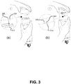
- a first mark (222) at the bottom of the upper module (220) is first aligned with a first mark (212) at the top of the lower module (210), as shown in Figure 3(a) .
- the two modules are pushed together longitudinally and then twisted axially relative to each other until locked, when a second mark (224) at the bottom of the upper module (220) is aligned with the first mark (212) of the lower module (210).
- each module has a body portion (400, 500), which includes a bottom mounting portion (410, 510) for mounting the module to an electrical module, such as another module, or a base (110 in Figure 4 ; not shown in Figure 5 ), below.
- Each body portion in this case also includes a top mounting portion (410, 520) for attachment to another module, or cap.
- Each module in these examples also includes a set of bottom electrodes (530 in Figure 5 ; not shown in Figure 4 ) near or at the bottom mounting portion (410, 510).
- Each module further includes a set of top electrodes (440 in Figure 4 ; not shown in Figure 5 ) corresponding to the respective bottom electrodes (530).
- the base (110) also has a set of electrodes (not shown) similar to the top electrodes (440) for lower module (210).
- the bottom electrodes (530) of upper module (220) are in contact with the electrodes in the electrical module, such as the top electrodes (440) of lower module (210) or the electrodes (118) of the base (110). See Figure 9 for an example in which an indicator module body portion (500) is mounted on a base (110).
- the top electrodes (440) are substantially flat and face the direction of the longitudinal axis of the lower module (210).
- the electrodes (118 in Figure 9 ) in the base (110) have a similar structure.
- the bottom electrodes (530) are flexible so that when the upper module (220) is mounted on the lower module (210) or a base (110), the bottom electrodes (530) are biased against the corresponding top electrodes (440) (or electrodes (118) in the base) to ensure proper electrical contact.
- the bottom electrodes (530) in one example, include a sloped section (532) obliquely facing the direction in which the module rotates relative to the module being attached thereto.
- This configuration ensures proper flex of the bottom electrodes (530) and prevents any protrusion on the top surface (624 in Figure 8 ) of the top circuit board (620 in Figure 8 ) of the module being attached to from impeding the relative rotation and proper locking between the two modules.
- An indicator module such as the audio module 170, can be designed to always be the top module in a stack, and as such, needs only to have a bottom mounting portion and bottom electrodes (details not shown).
- an indicator module in these examples further includes a switch module (550), which in the example shown in Figure 5 , is supported at the bottom of the upper module (220) but can be anywhere accessible by a user.
- the switch module (550) is used to selectively connect an indicator circuit (to be described later) in the upper module (220) to one of the bottom electrodes (530).
- each indicator module (210, 220) can also include a housing wall (460, 560), which in the case of an optical indicator module, may be a transparent or translucent wall for transmitting light emitted by an illumination source contained therein.
- the various electrical and electronic components (640) in an indicator module (210, 220) in this example are supported on a bottom circuit board (610) and a top circuit board (620).
- the bottom electrodes (530) and switch module (550) are supported on the bottom side (614) of the bottom circuit board (610), and the top electrodes (440) are supported on the top side (624) of the top circuit board (620).
- Each module further includes an indicator circuit, which in this example includes light sources (630), such as light emitting diodes (LEDs) and associated electronic components (640), which can include, for example, a driver circuit, blinker circuit and protection circuit.
- the light sources (630) are mounted on the bottom surface (622) of the top circuit board (620) and (not shown) on the top surface (612) of the bottom circuit board (610).
- the light sources (630) are also distributed near the periphery, or housing wall (560) of the upper module (220).
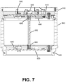
- Figure 7 shows a cross-sectional view of an indicator module, with the bottom circuit board (610) and top circuit board (620) interconnected via the conductors (650) and connectors (660), and with the light sources (630), other electronic components (640), bottom electrodes (530) and switch module (550) mounted the appropriate circuit boards (610, 620).
- each indicator module (210, 220) in this example further includes conductors (650) connecting the top electrodes (440 in Figures 4 and 8 ; not shown in Figure 5 or 6 ) to the bottom electrodes (not shown in Figure 4 ; 530 in Figures 5 and 6 ) within each module via connectors (660) and conductive lines (not shown) on the top and bottom circuit boards.
- the connectors (660) permit the top and bottom circuit boards (610, 620) to be readily assembled together or disassembled.
- the conductors (650) in this case are disposed in an interior region relative to the light sources (630). With this arrangement, shadows of the conductors (650) cast by the light sources (630) are reduced as compared to the arrangements in which the conductors are disposed near the periphery and light sources are disposed in a more interior region of the module.
- Figure 9 shows a cross-sectional view of an indicator module, with the bottom circuit board (610) and top circuit board (620) interconnected via the conductors (650) and connectors (660), and with the bottom electrodes (530), other electronic components (640), and the electrodes (118) of the base (110).
- each conductive path includes one conductor (650) and corresponding top and bottom electrodes (440, 530) in each module.
- one function of the switch is to selectively interconnect the indicator circuit, such as visual indicator circuit (630, 640), with one or more of the conductive paths.
- the indicator circuit in each indicator module can be connected between the common terminal (e.g., ground) and, via the switch module, selectively to one of the signal sources.
- the connection can be made, for example, to the bottom electrodes (530) via conductive lines (not shown) in the circuit board (610).
- the switch module (550) can be any suitable connecting device, including switches such as DIP switches, rotary switches, sliding switches, and the like. Though less convenient, the switching module (550) can also be a jumper arrangement.
- a part of a DIP switch (1050) is used for the purpose of selectively connecting an indicator circuit to one of the conductive paths.
- the DIP switch (1050) has several individual switches (1052, 1054), a subgroup (1052) of which serves to make the selective connections. For example, if the switch element in position "3" in a DIP switch in a module is switched to "ON,” the module is "seen” as M3, or Module 3, by the controller, regardless of the physical location of the indicator module in the sequence of modules in the assembly.
- two or more indicator modules, each occupying a different physical location, in an indicator assembly can be configured to be the same logical module by appropriate setting of the switch module (550). For example, if the switch element in position "3" in a DIP switch in each of two or more indicator modules in an indicator assembly is switched to "ON,” each of the modules is “seen” as M3, or Module 3, by the controller. Both or all of the modules set to M3 will be activated.
- both indicator modules can be set to the same logical module (e.g., both physical Module 6 (170) and physical Module 4 (210) can be set to be logical Module 3, or M3).
- the controller supplies power to the logical module (e.g., Module 3, or M3), both the audio and visual indicator modules will be activated and generate audio and visual signals, respectively.
- multiple visual indicator modules in an indicator assembly can be set to the same logical module to produce a desired array of visual signals, such as an array of lights of the same color or any other color pattern.
- switch module 550, 1050
- a portion of the DIP switch (1050) can be used to affect the type of indication provided by Module 3 (assuming the switch element in position "3" is "ON”).
- switch elements in positions "7" and “8” can be used to control whether the indicator module is active continuously or intermittently, and the frequency of intermittent indications (flashes or beeps).
- the circuit schematically shown in Figure 11 can be used to build a visual indicator module designed for tower lights having up to six independent channels.
- a portion (1052) of the switch module (1050) is used to selectively connect the light sources (630) and other electronics (640) via one of the six conductive paths (1110).
- the circuit (640) includes, among other things, a driver (642) for powering the light sources (630) and timing circuit (644).
- Another portion (1054) of the switch module (1050) is used to control the blinking indication of the light sources (630).
- Other suitable circuits can be used, depending the specific desired operation.
- the user configurable indicator modules described above can also be used with other types of indicator modules, such as traditional tower light modules, to achieve desired configurations.
- a device and method have been described, which, among other things, provide a high degree of flexibility in configuring modular indicator assemblies (tower lights and the like).
- the module can be configured to function as a module in any logical (electronic) position in a multi-indicator assembly, regardless of its location in the physical sequence of the indicator modules in the assembly.
- the arrangement of the conductive paths relative to optical indicator elements e.g., LEDs
- Resilient, or flexible, electrodes can be used for proper inter-modular electrical connections.
Landscapes
- Physics & Mathematics (AREA)
- General Physics & Mathematics (AREA)
- Electromagnetism (AREA)
- Switch Cases, Indication, And Locking (AREA)
- Illuminated Signs And Luminous Advertising (AREA)
Applications Claiming Priority (2)
| Application Number | Priority Date | Filing Date | Title |
|---|---|---|---|
| US14/803,619 US9997031B2 (en) | 2015-07-20 | 2015-07-20 | Modular indicator |
| EP16180316.8A EP3121798B1 (de) | 2015-07-20 | 2016-07-20 | Modularer indikator |
Related Parent Applications (1)
| Application Number | Title | Priority Date | Filing Date |
|---|---|---|---|
| EP16180316.8A Division EP3121798B1 (de) | 2015-07-20 | 2016-07-20 | Modularer indikator |
Publications (2)
| Publication Number | Publication Date |
|---|---|
| EP3901929A2 true EP3901929A2 (de) | 2021-10-27 |
| EP3901929A3 EP3901929A3 (de) | 2022-03-02 |
Family
ID=57144712
Family Applications (2)
| Application Number | Title | Priority Date | Filing Date |
|---|---|---|---|
| EP21174543.5A Withdrawn EP3901929A3 (de) | 2015-07-20 | 2016-07-20 | Modularer indikator |
| EP16180316.8A Active EP3121798B1 (de) | 2015-07-20 | 2016-07-20 | Modularer indikator |
Family Applications After (1)
| Application Number | Title | Priority Date | Filing Date |
|---|---|---|---|
| EP16180316.8A Active EP3121798B1 (de) | 2015-07-20 | 2016-07-20 | Modularer indikator |
Country Status (2)
| Country | Link |
|---|---|
| US (1) | US9997031B2 (de) |
| EP (2) | EP3901929A3 (de) |
Families Citing this family (13)
| Publication number | Priority date | Publication date | Assignee | Title |
|---|---|---|---|---|
| ES2631809T3 (es) * | 2015-01-12 | 2017-09-05 | Auer Signal Gmbh | Dispositivo de señalización |
| PT3076073T (pt) * | 2015-04-02 | 2017-06-09 | Schreder | Melhoramentos em ou relativos a conjuntos de luminárias modulares |
| WO2019241382A1 (en) * | 2018-06-12 | 2019-12-19 | Banner Engineering Corporation | Modular indicator |
| US10475299B2 (en) | 2015-07-20 | 2019-11-12 | Banner Engineering Corporation | Modular indicator |
| USD839119S1 (en) * | 2015-12-24 | 2019-01-29 | Patlite Corporation | Signal warning and displaying lamp |
| USD898600S1 (en) | 2017-07-20 | 2020-10-13 | Mallory Sonalert Products, Inc. | Stack light |
| US11415281B2 (en) * | 2018-08-28 | 2022-08-16 | Mary Elle Fashions, Inc. | Flickering mineral light |
| BE1027040B1 (nl) * | 2019-02-08 | 2020-09-07 | Picanol Nv | Signaleringssysteem voor een weefmachine |
| CN117121070A (zh) * | 2020-12-18 | 2023-11-24 | 邦纳工程公司 | 直列式模块化指示器组件 |
| USD974939S1 (en) * | 2021-07-14 | 2023-01-10 | Shengzhe Chen | LED warning light |
| CN218762830U (zh) * | 2022-06-20 | 2023-03-28 | 深圳市智岩科技有限公司 | 一种照明灯 |
| USD1083918S1 (en) * | 2022-09-27 | 2025-07-15 | Banner Engineering Corp. | Removable cover for data processing equipment |
| USD1120791S1 (en) * | 2024-03-20 | 2026-03-31 | Schneider Electric Industries Sas | Luminous signalling device |
Family Cites Families (100)
| Publication number | Priority date | Publication date | Assignee | Title |
|---|---|---|---|---|
| FR2128998A5 (de) | 1971-03-10 | 1972-10-27 | Telemecanique Electrique | |
| US3868671A (en) | 1973-06-07 | 1975-02-25 | Hugh F Maguire | Basketball foul indicia display apparatus |
| US5416706A (en) | 1984-04-27 | 1995-05-16 | Hagenbuch; Leroy G. | Apparatus for identifying containers from which refuse is collected and compiling a historical record of the containers |
| US4839835A (en) | 1984-04-27 | 1989-06-13 | Hagenbuch Roy George Le | Apparatus and method responsive to the on-board measuring of the load carried by a truck body |
| US5327347A (en) | 1984-04-27 | 1994-07-05 | Hagenbuch Roy George Le | Apparatus and method responsive to the on-board measuring of haulage parameters of a vehicle |
| US5644489A (en) | 1984-04-27 | 1997-07-01 | Hagenbuch; Leroy G. | Apparatus and method for identifying containers from which material is collected and loaded onto a haulage vehicle |
| US5453729A (en) | 1993-07-28 | 1995-09-26 | Chu; Chiu-Tsai | Solar warning light |
| JPH07201210A (ja) | 1993-12-29 | 1995-08-04 | Patoraito:Kk | 信号表示灯の光源構造 |
| US5952915A (en) | 1994-04-15 | 1999-09-14 | Werma-Signalgeraete Gmbh & Co. | Signal pillar |
| USD363250S (en) | 1994-04-29 | 1995-10-17 | Patlite Corporation | Signal lamp |
| USD363036S (en) | 1994-06-16 | 1995-10-10 | Patlite Corporation | Signal lamp |
| USD363675S (en) | 1995-01-25 | 1995-10-31 | Patlite Corporation | Combined warning light and siren housing for emergency vehicles |
| JPH09167508A (ja) * | 1995-12-15 | 1997-06-24 | Patoraito:Kk | 信号報知表示灯 |
| TW402856B (en) | 1996-12-26 | 2000-08-21 | Palite Corp | LED illuminator |
| US5963126A (en) | 1997-02-27 | 1999-10-05 | Star Headlight And Lantern Co, Inc | Visual signaling device |
| USD408938S (en) | 1997-05-16 | 1999-04-27 | Patlite Corporation | Wall mounted housing for rotary security light |
| US6586255B1 (en) | 1997-07-21 | 2003-07-01 | Quest Diagnostics Incorporated | Automated centrifuge loading device |
| US6589789B1 (en) | 1997-07-21 | 2003-07-08 | Quest Diagnostics Incorporated | Automated centrifuge loading device |
| DE19829971B4 (de) | 1998-07-04 | 2010-07-15 | Werma Holding Gmbh + Co. Kg | Signalgeber |
| DE19854666C2 (de) | 1998-11-26 | 2003-01-02 | Schneider Electric Gmbh | Signaleinrichtung |
| JP2000268604A (ja) | 1999-03-19 | 2000-09-29 | Patoraito:Kk | Led表示灯 |
| US6135612A (en) | 1999-03-29 | 2000-10-24 | Clore; William B. | Display unit |
| FR2794217B1 (fr) | 1999-05-28 | 2001-07-20 | Schneider Electric Ind Sa | Element de colonne lumineuse |
| JP3644482B2 (ja) | 1999-05-31 | 2005-04-27 | 株式会社パトライト | 表示灯 |
| USD428821S (en) | 1999-06-25 | 2000-08-01 | Patlite Corporation | Globe for a signal illuminating lamp |
| USD432038S (en) | 2000-02-15 | 2000-10-17 | Patlite Corporation | Combined warning light and siren housing for emergency vehicles |
| USD432444S (en) | 2000-02-15 | 2000-10-24 | Patlite Corporation | Warning light housing for emergency vehicles |
| EP1146280B1 (de) | 2000-04-12 | 2009-12-09 | WERMA Holding GmbH + Co. KG | Signalgerät |
| EP1146278A3 (de) | 2000-04-12 | 2004-01-21 | WERMA Signaltechnik GmbH & Co. | Leuchtmittel, insbesondere für eine Signalleuchte |
| US6705060B1 (en) | 2000-10-24 | 2004-03-16 | Applied Technology Group, Inc. | Method and apparatus for wrapping a coil |
| DE10111594A1 (de) * | 2001-03-10 | 2002-09-19 | Karl Jautz Elektro Tech Spezia | Anzeigeleuchtensäule |
| US20030030567A1 (en) | 2001-08-13 | 2003-02-13 | Hetzel William Hieby | Flexible functionality of stack light |
| CN100488443C (zh) | 2002-02-19 | 2009-05-20 | 沃尔沃技术公司 | 用于监视和管理司机注意力负荷的系统和方法 |
| JP2003249383A (ja) | 2002-02-25 | 2003-09-05 | Patoraito:Kk | Led表示灯の故障診断回路 |
| US7224825B2 (en) | 2002-04-18 | 2007-05-29 | Lockheed Martin Corporation | Detecting and identifying hazardous substances contained in mail articles |
| US6964372B1 (en) | 2002-08-13 | 2005-11-15 | Peterson William M | Conference-table-based wired information system |
| US7014030B2 (en) | 2003-01-22 | 2006-03-21 | Hendzel Louis J | Modular substructure for material handling |
| JP4134748B2 (ja) | 2003-02-21 | 2008-08-20 | 株式会社パトライト | 信号表示灯用ユニットおよび信号表示灯 |
| US6869320B2 (en) * | 2003-04-23 | 2005-03-22 | Hewlett-Packard Development Company, L.P. | Portable modular electronic system with symmetrical connections |
| USD519869S1 (en) | 2003-05-30 | 2006-05-02 | Patlite Corporation | Alarm device |
| CN1802273B (zh) | 2003-06-06 | 2010-05-12 | 沃尔沃技术公司 | 根据被解释的驾驶员活动控制车辆子系统的方法和装置 |
| US7436504B2 (en) | 2003-09-10 | 2008-10-14 | Shear Graphics, Llc | Non-destructive testing and imaging |
| EP1575011B1 (de) | 2004-03-11 | 2012-05-09 | WERMA Holding GmbH + Co. KG | Signalgerät |
| PT1735561E (pt) | 2004-04-08 | 2008-10-09 | Schneider Electric Ind Sas | Coluna de sinalização |
| US8192292B2 (en) | 2004-06-23 | 2012-06-05 | Quibicamp Worldwide LLC | Automated bowling system, controller and method of use |
| JP4089692B2 (ja) | 2004-09-02 | 2008-05-28 | 株式会社パトライト | レンズ部品、信号表示灯用表示ユニットおよび信号表示灯 |
| EP1650489B1 (de) | 2004-10-22 | 2007-08-22 | WERMA Signaltechnik GmbH & Co.KG | Signalgerät, insbesondere Signalsäule |
| USD565788S1 (en) | 2004-11-01 | 2008-04-01 | Patlite Corporation | Warning lamp |
| USD518400S1 (en) | 2004-12-10 | 2006-04-04 | Patlite Corporation | Combined warning light and siren housing for emergency vehicles |
| JP4319973B2 (ja) | 2004-12-13 | 2009-08-26 | Idec株式会社 | リレー |
| USD557159S1 (en) | 2004-12-14 | 2007-12-11 | Patlite Corporation | Globe for a warning lamp |
| USD555025S1 (en) | 2004-12-27 | 2007-11-13 | Patlite Corporation | Globe for a warning lamp |
| JP4522291B2 (ja) | 2005-03-08 | 2010-08-11 | Idec株式会社 | 安全スイッチ |
| JP4673661B2 (ja) | 2005-04-26 | 2011-04-20 | Idec株式会社 | 安全スイッチ |
| JP4727290B2 (ja) | 2005-05-11 | 2011-07-20 | Idec株式会社 | 安全スイッチ |
| JP4616098B2 (ja) | 2005-07-13 | 2011-01-19 | Idec株式会社 | 安全スイッチ付き扉ロック装置 |
| CN100548658C (zh) | 2005-07-19 | 2009-10-14 | 欧姆龙株式会社 | 双手开关设备 |
| CN101142063B (zh) | 2005-07-19 | 2010-05-19 | 欧姆龙株式会社 | 作业人员安全管理系统 |
| US8260948B2 (en) | 2005-08-10 | 2012-09-04 | Rockwell Automation Technologies, Inc. | Enhanced controller utilizing RFID technology |
| JP4665231B2 (ja) | 2005-09-05 | 2011-04-06 | Idec株式会社 | 安全保持具 |
| US7722215B2 (en) | 2006-01-06 | 2010-05-25 | Barco, Inc. | 360 degree viewable light emitting apparatus |
| US20110103050A1 (en) | 2006-01-06 | 2011-05-05 | Jeremy Hochman | 360 Degree Viewable Light Emitting Apparatus |
| CN101103425B (zh) | 2006-02-02 | 2011-09-28 | Idec株式会社 | 按钮开关装置 |
| US8615374B1 (en) | 2006-06-09 | 2013-12-24 | Rockwell Automation Technologies, Inc. | Modular, configurable, intelligent sensor system |
| US8120489B2 (en) | 2006-06-09 | 2012-02-21 | Oracle International Corporation | Workflow improvements |
| BRPI0712837B8 (pt) | 2006-06-11 | 2021-06-22 | Volvo Tech Corporation | método para determinação e análise de uma localização de interesse visual |
| JP4965196B2 (ja) | 2006-08-29 | 2012-07-04 | Idec株式会社 | 押ボタンスイッチ装置 |
| US8000835B2 (en) | 2006-12-01 | 2011-08-16 | Lockheed Martin Corporation | Center of gravity sensing and adjusting load bar, program product, and related methods |
| US8542104B2 (en) | 2007-03-01 | 2013-09-24 | Oracle International Corporation | RFID edge server having a programmable logic controller API |
| AU2008201153C1 (en) | 2007-03-28 | 2011-01-06 | Aristocrat Technologies Australia Pty Limited | A Modular Visual Output Component |
| US7880637B2 (en) | 2007-06-11 | 2011-02-01 | Seegrid Corporation | Low-profile signal device and method for providing color-coded signals |
| USD586033S1 (en) | 2007-08-03 | 2009-02-03 | Patlite Corporation | Reflector for rotary warning lamp |
| TWD127074S1 (zh) | 2007-08-03 | 2009-01-11 | 派特萊特股份有限公司 | 照明裝置用外盒 |
| DE102007052377B4 (de) | 2007-10-31 | 2015-04-02 | Werma Holding Gmbh + Co. Kg | Warnleuchte zur optischen Anzeige von wenigstens einem Betriebszustand |
| JP5483389B2 (ja) | 2008-01-31 | 2014-05-07 | Idec株式会社 | 電気回路 |
| USD598315S1 (en) | 2008-03-22 | 2009-08-18 | Patlite Corporation | Signal warning and displaying lamp |
| USD604652S1 (en) | 2008-04-17 | 2009-11-24 | Werma Signaltechnik Gmbh + Co. Kg | Signal device |
| US8487747B2 (en) | 2008-05-23 | 2013-07-16 | At&T Intellectual Property I, L.P. | Method and system for controlling the traffic flow through an RFID directional portal |
| USD598316S1 (en) | 2008-06-12 | 2009-08-18 | Patlite Corporation | Globe for revolving warning light |
| USD598799S1 (en) | 2008-06-12 | 2009-08-25 | Patlite Corporation | Revolving warning light |
| US7950088B2 (en) | 2008-07-01 | 2011-05-31 | Whirlpool Corporation | Method of indicating operational information for a dispensing system having both single use and bulk dispensing |
| US8286288B2 (en) | 2008-07-01 | 2012-10-16 | Whirlpool Corporation | Method of indicating operational information for a bulk dispensing system |
| ATE531014T1 (de) | 2008-11-04 | 2011-11-15 | Werma Holding Gmbh & Co Kg | Warnleuchtvorrichtung mit wenigstens zwei warnleuchten |
| EP2209099B1 (de) | 2008-11-04 | 2011-10-26 | WERMA Holding GmbH + Co. KG | Warnleuchtvorrichtung mit wenigstens zwei Warnleuchten |
| USD655216S1 (en) | 2009-03-26 | 2012-03-06 | Werma Holding Gmbh + Co. Kg | Signal device |
| JP5403255B2 (ja) | 2009-11-17 | 2014-01-29 | セイコーエプソン株式会社 | 照明装置およびプロジェクター |
| TWD143091S1 (zh) | 2010-03-31 | 2011-10-01 | 派特萊特股份有限公司 | 照明裝置 |
| USD651109S1 (en) | 2010-06-30 | 2011-12-27 | Patlite Corporation | Signal warning and displaying lamp |
| USD651111S1 (en) | 2010-08-23 | 2011-12-27 | Patlite Corporation | Signal warning and displaying lamp |
| USD647812S1 (en) | 2010-08-23 | 2011-11-01 | Patlite Corporation | Signal warning and displaying lamp |
| USD648241S1 (en) | 2010-08-23 | 2011-11-08 | Patlite Corporation | Signal warning and displaying lamp |
| TWD144285S (zh) | 2010-08-23 | 2011-12-11 | 派特萊特股份有限公司 | 信號報知顯示燈 |
| USD651112S1 (en) | 2011-01-17 | 2011-12-27 | Patlite Corporation | Signal warning and displaying lamp |
| USD653141S1 (en) | 2011-01-17 | 2012-01-31 | Patlite Corporation | Signal warning and displaying lamp |
| DE102011080595B4 (de) | 2011-08-08 | 2014-05-15 | Compro Electronic Gmbh | Lichtsignalmodul |
| TWD153389S (zh) | 2011-11-02 | 2013-05-01 | 派特萊特股份有限公司 | 照明裝置 |
| US20140071681A1 (en) * | 2012-03-14 | 2014-03-13 | Project Aj, Inc. | Cone light |
| US9175827B2 (en) | 2012-05-09 | 2015-11-03 | Lee Clore | Indicator light tower technology |
| US20150198317A1 (en) | 2014-01-13 | 2015-07-16 | Rockwell Automation Technologies, Inc. | Stack Light with Modular Power Converter |
| US9307309B2 (en) * | 2014-01-13 | 2016-04-05 | Rockwell Automation Technologies, Inc. | Stack light with in-line sound module |
-
2015
- 2015-07-20 US US14/803,619 patent/US9997031B2/en active Active
-
2016
- 2016-07-20 EP EP21174543.5A patent/EP3901929A3/de not_active Withdrawn
- 2016-07-20 EP EP16180316.8A patent/EP3121798B1/de active Active
Also Published As
| Publication number | Publication date |
|---|---|
| US20170024977A1 (en) | 2017-01-26 |
| US9997031B2 (en) | 2018-06-12 |
| EP3121798B1 (de) | 2021-05-19 |
| EP3901929A3 (de) | 2022-03-02 |
| EP3121798A1 (de) | 2017-01-25 |
Similar Documents
| Publication | Publication Date | Title |
|---|---|---|
| US9997031B2 (en) | Modular indicator | |
| US11580828B2 (en) | Modular indicator | |
| CN101636616B (zh) | 模块化电气系统 | |
| US8184445B2 (en) | Modular electric system | |
| US9734965B2 (en) | Arrangement of pushbutton switches with a programmable display | |
| EP2663164B1 (de) | Kommunikationsmodul und Beleuchtungsvorrichtung damit | |
| US6149288A (en) | Vehicle light assembly with detachable and replaceable circuit board having plug-in terminal connectors | |
| US5062807A (en) | Lighted electrical connector permitting multi directional viewing | |
| EP3394502B1 (de) | Modulare leuchte | |
| US20130163249A1 (en) | Led wiring board and light irradiation apparatus | |
| EP2525144B1 (de) | Beleuchtungsvorrichtung und Beleuchtungsinstrument | |
| WO2014195801A2 (en) | Modular light emitting diode lighting system | |
| US20150117005A1 (en) | Light fixture | |
| EP3297164A1 (de) | Berührungsschalter und innenbeleuchtungsvorrichtung für fahrzeug damit | |
| EP1381810A1 (de) | Biegsame leiterplatte mit beleuchtung durch leds | |
| CN104798118B (zh) | 信号柱 | |
| US20090168437A1 (en) | Tricolor signal housing | |
| CN102160263B (zh) | 用于电连接电动机的接线盒 | |
| CN104379989A (zh) | 连接模块、供电模块和用于发光带的连接组件 | |
| CN112601910B (zh) | 模块化指示器 | |
| CN204062827U (zh) | 照明器具 | |
| JP6003236B2 (ja) | Ledランプ取付構造 | |
| EP2851916B1 (de) | Anordnung aus tastenschaltern mit programmierbarer anzeige | |
| KR20070117252A (ko) | 엘이디 조명 모듈의 연결장치 |
Legal Events
| Date | Code | Title | Description |
|---|---|---|---|
| PUAI | Public reference made under article 153(3) epc to a published international application that has entered the european phase |
Free format text: ORIGINAL CODE: 0009012 |
|
| STAA | Information on the status of an ep patent application or granted ep patent |
Free format text: STATUS: THE APPLICATION HAS BEEN PUBLISHED |
|
| AC | Divisional application: reference to earlier application |
Ref document number: 3121798 Country of ref document: EP Kind code of ref document: P |
|
| AK | Designated contracting states |
Kind code of ref document: A2 Designated state(s): AL AT BE BG CH CY CZ DE DK EE ES FI FR GB GR HR HU IE IS IT LI LT LU LV MC MK MT NL NO PL PT RO RS SE SI SK SM TR |
|
| PUAL | Search report despatched |
Free format text: ORIGINAL CODE: 0009013 |
|
| AK | Designated contracting states |
Kind code of ref document: A3 Designated state(s): AL AT BE BG CH CY CZ DE DK EE ES FI FR GB GR HR HU IE IS IT LI LT LU LV MC MK MT NL NO PL PT RO RS SE SI SK SM TR |
|
| RIC1 | Information provided on ipc code assigned before grant |
Ipc: G08B 7/06 20060101ALI20220124BHEP Ipc: G08B 5/36 20060101AFI20220124BHEP |
|
| STAA | Information on the status of an ep patent application or granted ep patent |
Free format text: STATUS: THE APPLICATION IS DEEMED TO BE WITHDRAWN |
|
| 18D | Application deemed to be withdrawn |
Effective date: 20220903 |