EP3901970B1 - Tôle d'acier électrique à grains orientés et son procédé de fabrication - Google Patents
Tôle d'acier électrique à grains orientés et son procédé de fabrication Download PDFInfo
- Publication number
- EP3901970B1 EP3901970B1 EP19898832.1A EP19898832A EP3901970B1 EP 3901970 B1 EP3901970 B1 EP 3901970B1 EP 19898832 A EP19898832 A EP 19898832A EP 3901970 B1 EP3901970 B1 EP 3901970B1
- Authority
- EP
- European Patent Office
- Prior art keywords
- groove
- steel sheet
- electrical steel
- oriented electrical
- grain
- Prior art date
- Legal status (The legal status is an assumption and is not a legal conclusion. Google has not performed a legal analysis and makes no representation as to the accuracy of the status listed.)
- Active
Links
Images


Classifications
-
- H—ELECTRICITY
- H01—ELECTRIC ELEMENTS
- H01F—MAGNETS; INDUCTANCES; TRANSFORMERS; SELECTION OF MATERIALS FOR THEIR MAGNETIC PROPERTIES
- H01F1/00—Magnets or magnetic bodies characterised by the magnetic materials therefor; Selection of materials for their magnetic properties
- H01F1/01—Magnets or magnetic bodies characterised by the magnetic materials therefor; Selection of materials for their magnetic properties of inorganic materials
- H01F1/03—Magnets or magnetic bodies characterised by the magnetic materials therefor; Selection of materials for their magnetic properties of inorganic materials characterised by their coercivity
- H01F1/12—Magnets or magnetic bodies characterised by the magnetic materials therefor; Selection of materials for their magnetic properties of inorganic materials characterised by their coercivity of soft-magnetic materials
- H01F1/14—Magnets or magnetic bodies characterised by the magnetic materials therefor; Selection of materials for their magnetic properties of inorganic materials characterised by their coercivity of soft-magnetic materials metals or alloys
- H01F1/16—Magnets or magnetic bodies characterised by the magnetic materials therefor; Selection of materials for their magnetic properties of inorganic materials characterised by their coercivity of soft-magnetic materials metals or alloys in the form of sheets
-
- C—CHEMISTRY; METALLURGY
- C23—COATING METALLIC MATERIAL; COATING MATERIAL WITH METALLIC MATERIAL; CHEMICAL SURFACE TREATMENT; DIFFUSION TREATMENT OF METALLIC MATERIAL; COATING BY VACUUM EVAPORATION, BY SPUTTERING, BY ION IMPLANTATION OR BY CHEMICAL VAPOUR DEPOSITION, IN GENERAL; INHIBITING CORROSION OF METALLIC MATERIAL OR INCRUSTATION IN GENERAL
- C23C—COATING METALLIC MATERIAL; COATING MATERIAL WITH METALLIC MATERIAL; SURFACE TREATMENT OF METALLIC MATERIAL BY DIFFUSION INTO THE SURFACE, BY CHEMICAL CONVERSION OR SUBSTITUTION; COATING BY VACUUM EVAPORATION, BY SPUTTERING, BY ION IMPLANTATION OR BY CHEMICAL VAPOUR DEPOSITION, IN GENERAL
- C23C30/00—Coating with metallic material characterised only by the composition of the metallic material, i.e. not characterised by the coating process
-
- B—PERFORMING OPERATIONS; TRANSPORTING
- B23—MACHINE TOOLS; METAL-WORKING NOT OTHERWISE PROVIDED FOR
- B23K—SOLDERING OR UNSOLDERING; WELDING; CLADDING OR PLATING BY SOLDERING OR WELDING; CUTTING BY APPLYING HEAT LOCALLY, e.g. FLAME CUTTING; WORKING BY LASER BEAM
- B23K26/00—Working by laser beam, e.g. welding, cutting or boring
- B23K26/36—Removing material
- B23K26/362—Laser etching
- B23K26/364—Laser etching for making a groove or trench, e.g. for scribing a break initiation groove
-
- C—CHEMISTRY; METALLURGY
- C21—METALLURGY OF IRON
- C21D—MODIFYING THE PHYSICAL STRUCTURE OF FERROUS METALS; GENERAL DEVICES FOR HEAT TREATMENT OF FERROUS OR NON-FERROUS METALS OR ALLOYS; MAKING METAL MALLEABLE, e.g. BY DECARBURISATION OR TEMPERING
- C21D1/00—General methods or devices for heat treatment, e.g. annealing, hardening, quenching or tempering
- C21D1/26—Methods of annealing
-
- C—CHEMISTRY; METALLURGY
- C21—METALLURGY OF IRON
- C21D—MODIFYING THE PHYSICAL STRUCTURE OF FERROUS METALS; GENERAL DEVICES FOR HEAT TREATMENT OF FERROUS OR NON-FERROUS METALS OR ALLOYS; MAKING METAL MALLEABLE, e.g. BY DECARBURISATION OR TEMPERING
- C21D10/00—Modifying the physical properties by methods other than heat treatment or deformation
- C21D10/005—Modifying the physical properties by methods other than heat treatment or deformation by laser shock processing
-
- C—CHEMISTRY; METALLURGY
- C21—METALLURGY OF IRON
- C21D—MODIFYING THE PHYSICAL STRUCTURE OF FERROUS METALS; GENERAL DEVICES FOR HEAT TREATMENT OF FERROUS OR NON-FERROUS METALS OR ALLOYS; MAKING METAL MALLEABLE, e.g. BY DECARBURISATION OR TEMPERING
- C21D8/00—Modifying the physical properties of ferrous metals or ferrous alloys by deformation combined with, or followed by, heat treatment
- C21D8/02—Modifying the physical properties of ferrous metals or ferrous alloys by deformation combined with, or followed by, heat treatment during manufacturing of plates or strips
- C21D8/0247—Modifying the physical properties of ferrous metals or ferrous alloys by deformation combined with, or followed by, heat treatment during manufacturing of plates or strips characterised by the heat treatment
- C21D8/0273—Final recrystallisation annealing
-
- C—CHEMISTRY; METALLURGY
- C21—METALLURGY OF IRON
- C21D—MODIFYING THE PHYSICAL STRUCTURE OF FERROUS METALS; GENERAL DEVICES FOR HEAT TREATMENT OF FERROUS OR NON-FERROUS METALS OR ALLOYS; MAKING METAL MALLEABLE, e.g. BY DECARBURISATION OR TEMPERING
- C21D8/00—Modifying the physical properties of ferrous metals or ferrous alloys by deformation combined with, or followed by, heat treatment
- C21D8/12—Modifying the physical properties of ferrous metals or ferrous alloys by deformation combined with, or followed by, heat treatment during manufacturing of articles with special electromagnetic properties
- C21D8/1216—Modifying the physical properties of ferrous metals or ferrous alloys by deformation combined with, or followed by, heat treatment during manufacturing of articles with special electromagnetic properties characterised by the working steps
- C21D8/1233—Cold rolling
-
- C—CHEMISTRY; METALLURGY
- C21—METALLURGY OF IRON
- C21D—MODIFYING THE PHYSICAL STRUCTURE OF FERROUS METALS; GENERAL DEVICES FOR HEAT TREATMENT OF FERROUS OR NON-FERROUS METALS OR ALLOYS; MAKING METAL MALLEABLE, e.g. BY DECARBURISATION OR TEMPERING
- C21D8/00—Modifying the physical properties of ferrous metals or ferrous alloys by deformation combined with, or followed by, heat treatment
- C21D8/12—Modifying the physical properties of ferrous metals or ferrous alloys by deformation combined with, or followed by, heat treatment during manufacturing of articles with special electromagnetic properties
- C21D8/1244—Modifying the physical properties of ferrous metals or ferrous alloys by deformation combined with, or followed by, heat treatment during manufacturing of articles with special electromagnetic properties characterised by the heat treatment
- C21D8/1266—Modifying the physical properties of ferrous metals or ferrous alloys by deformation combined with, or followed by, heat treatment during manufacturing of articles with special electromagnetic properties characterised by the heat treatment between cold rolling steps
-
- C—CHEMISTRY; METALLURGY
- C21—METALLURGY OF IRON
- C21D—MODIFYING THE PHYSICAL STRUCTURE OF FERROUS METALS; GENERAL DEVICES FOR HEAT TREATMENT OF FERROUS OR NON-FERROUS METALS OR ALLOYS; MAKING METAL MALLEABLE, e.g. BY DECARBURISATION OR TEMPERING
- C21D8/00—Modifying the physical properties of ferrous metals or ferrous alloys by deformation combined with, or followed by, heat treatment
- C21D8/12—Modifying the physical properties of ferrous metals or ferrous alloys by deformation combined with, or followed by, heat treatment during manufacturing of articles with special electromagnetic properties
- C21D8/1244—Modifying the physical properties of ferrous metals or ferrous alloys by deformation combined with, or followed by, heat treatment during manufacturing of articles with special electromagnetic properties characterised by the heat treatment
- C21D8/1272—Final recrystallisation annealing
-
- C—CHEMISTRY; METALLURGY
- C21—METALLURGY OF IRON
- C21D—MODIFYING THE PHYSICAL STRUCTURE OF FERROUS METALS; GENERAL DEVICES FOR HEAT TREATMENT OF FERROUS OR NON-FERROUS METALS OR ALLOYS; MAKING METAL MALLEABLE, e.g. BY DECARBURISATION OR TEMPERING
- C21D8/00—Modifying the physical properties of ferrous metals or ferrous alloys by deformation combined with, or followed by, heat treatment
- C21D8/12—Modifying the physical properties of ferrous metals or ferrous alloys by deformation combined with, or followed by, heat treatment during manufacturing of articles with special electromagnetic properties
- C21D8/1277—Modifying the physical properties of ferrous metals or ferrous alloys by deformation combined with, or followed by, heat treatment during manufacturing of articles with special electromagnetic properties involving a particular surface treatment
- C21D8/1283—Application of a separating or insulating coating
-
- C—CHEMISTRY; METALLURGY
- C21—METALLURGY OF IRON
- C21D—MODIFYING THE PHYSICAL STRUCTURE OF FERROUS METALS; GENERAL DEVICES FOR HEAT TREATMENT OF FERROUS OR NON-FERROUS METALS OR ALLOYS; MAKING METAL MALLEABLE, e.g. BY DECARBURISATION OR TEMPERING
- C21D9/00—Heat treatment, e.g. annealing, hardening, quenching or tempering, adapted for particular articles; Furnaces therefor
- C21D9/46—Heat treatment, e.g. annealing, hardening, quenching or tempering, adapted for particular articles; Furnaces therefor for sheet metals
-
- H—ELECTRICITY
- H01—ELECTRIC ELEMENTS
- H01F—MAGNETS; INDUCTANCES; TRANSFORMERS; SELECTION OF MATERIALS FOR THEIR MAGNETIC PROPERTIES
- H01F1/00—Magnets or magnetic bodies characterised by the magnetic materials therefor; Selection of materials for their magnetic properties
- H01F1/01—Magnets or magnetic bodies characterised by the magnetic materials therefor; Selection of materials for their magnetic properties of inorganic materials
- H01F1/03—Magnets or magnetic bodies characterised by the magnetic materials therefor; Selection of materials for their magnetic properties of inorganic materials characterised by their coercivity
- H01F1/12—Magnets or magnetic bodies characterised by the magnetic materials therefor; Selection of materials for their magnetic properties of inorganic materials characterised by their coercivity of soft-magnetic materials
- H01F1/14—Magnets or magnetic bodies characterised by the magnetic materials therefor; Selection of materials for their magnetic properties of inorganic materials characterised by their coercivity of soft-magnetic materials metals or alloys
- H01F1/16—Magnets or magnetic bodies characterised by the magnetic materials therefor; Selection of materials for their magnetic properties of inorganic materials characterised by their coercivity of soft-magnetic materials metals or alloys in the form of sheets
- H01F1/18—Magnets or magnetic bodies characterised by the magnetic materials therefor; Selection of materials for their magnetic properties of inorganic materials characterised by their coercivity of soft-magnetic materials metals or alloys in the form of sheets with insulating coating
-
- H—ELECTRICITY
- H01—ELECTRIC ELEMENTS
- H01F—MAGNETS; INDUCTANCES; TRANSFORMERS; SELECTION OF MATERIALS FOR THEIR MAGNETIC PROPERTIES
- H01F41/00—Apparatus or processes specially adapted for manufacturing or assembling magnets, inductances or transformers; Apparatus or processes specially adapted for manufacturing materials characterised by their magnetic properties
- H01F41/02—Apparatus or processes specially adapted for manufacturing or assembling magnets, inductances or transformers; Apparatus or processes specially adapted for manufacturing materials characterised by their magnetic properties for manufacturing cores, coils, or magnets
- H01F41/0206—Manufacturing of magnetic cores by mechanical means
- H01F41/0233—Manufacturing of magnetic circuits made from sheets
-
- C—CHEMISTRY; METALLURGY
- C21—METALLURGY OF IRON
- C21D—MODIFYING THE PHYSICAL STRUCTURE OF FERROUS METALS; GENERAL DEVICES FOR HEAT TREATMENT OF FERROUS OR NON-FERROUS METALS OR ALLOYS; MAKING METAL MALLEABLE, e.g. BY DECARBURISATION OR TEMPERING
- C21D1/00—General methods or devices for heat treatment, e.g. annealing, hardening, quenching or tempering
- C21D1/74—Methods of treatment in inert gas, controlled atmosphere, vacuum or pulverulent material
- C21D1/76—Adjusting the composition of the atmosphere
-
- C—CHEMISTRY; METALLURGY
- C21—METALLURGY OF IRON
- C21D—MODIFYING THE PHYSICAL STRUCTURE OF FERROUS METALS; GENERAL DEVICES FOR HEAT TREATMENT OF FERROUS OR NON-FERROUS METALS OR ALLOYS; MAKING METAL MALLEABLE, e.g. BY DECARBURISATION OR TEMPERING
- C21D2201/00—Treatment for obtaining particular effects
- C21D2201/05—Grain orientation
-
- C—CHEMISTRY; METALLURGY
- C23—COATING METALLIC MATERIAL; COATING MATERIAL WITH METALLIC MATERIAL; CHEMICAL SURFACE TREATMENT; DIFFUSION TREATMENT OF METALLIC MATERIAL; COATING BY VACUUM EVAPORATION, BY SPUTTERING, BY ION IMPLANTATION OR BY CHEMICAL VAPOUR DEPOSITION, IN GENERAL; INHIBITING CORROSION OF METALLIC MATERIAL OR INCRUSTATION IN GENERAL
- C23C—COATING METALLIC MATERIAL; COATING MATERIAL WITH METALLIC MATERIAL; SURFACE TREATMENT OF METALLIC MATERIAL BY DIFFUSION INTO THE SURFACE, BY CHEMICAL CONVERSION OR SUBSTITUTION; COATING BY VACUUM EVAPORATION, BY SPUTTERING, BY ION IMPLANTATION OR BY CHEMICAL VAPOUR DEPOSITION, IN GENERAL
- C23C8/00—Solid state diffusion of only non-metal elements into metallic material surfaces; Chemical surface treatment of metallic material by reaction of the surface with a reactive gas, leaving reaction products of surface material in the coating, e.g. conversion coatings, passivation of metals
- C23C8/06—Solid state diffusion of only non-metal elements into metallic material surfaces; Chemical surface treatment of metallic material by reaction of the surface with a reactive gas, leaving reaction products of surface material in the coating, e.g. conversion coatings, passivation of metals using gases
- C23C8/08—Solid state diffusion of only non-metal elements into metallic material surfaces; Chemical surface treatment of metallic material by reaction of the surface with a reactive gas, leaving reaction products of surface material in the coating, e.g. conversion coatings, passivation of metals using gases only one element being applied
- C23C8/10—Oxidising
- C23C8/12—Oxidising using elemental oxygen or ozone
- C23C8/14—Oxidising of ferrous surfaces
-
- C—CHEMISTRY; METALLURGY
- C23—COATING METALLIC MATERIAL; COATING MATERIAL WITH METALLIC MATERIAL; CHEMICAL SURFACE TREATMENT; DIFFUSION TREATMENT OF METALLIC MATERIAL; COATING BY VACUUM EVAPORATION, BY SPUTTERING, BY ION IMPLANTATION OR BY CHEMICAL VAPOUR DEPOSITION, IN GENERAL; INHIBITING CORROSION OF METALLIC MATERIAL OR INCRUSTATION IN GENERAL
- C23C—COATING METALLIC MATERIAL; COATING MATERIAL WITH METALLIC MATERIAL; SURFACE TREATMENT OF METALLIC MATERIAL BY DIFFUSION INTO THE SURFACE, BY CHEMICAL CONVERSION OR SUBSTITUTION; COATING BY VACUUM EVAPORATION, BY SPUTTERING, BY ION IMPLANTATION OR BY CHEMICAL VAPOUR DEPOSITION, IN GENERAL
- C23C8/00—Solid state diffusion of only non-metal elements into metallic material surfaces; Chemical surface treatment of metallic material by reaction of the surface with a reactive gas, leaving reaction products of surface material in the coating, e.g. conversion coatings, passivation of metals
- C23C8/06—Solid state diffusion of only non-metal elements into metallic material surfaces; Chemical surface treatment of metallic material by reaction of the surface with a reactive gas, leaving reaction products of surface material in the coating, e.g. conversion coatings, passivation of metals using gases
- C23C8/08—Solid state diffusion of only non-metal elements into metallic material surfaces; Chemical surface treatment of metallic material by reaction of the surface with a reactive gas, leaving reaction products of surface material in the coating, e.g. conversion coatings, passivation of metals using gases only one element being applied
- C23C8/10—Oxidising
- C23C8/16—Oxidising using oxygen-containing compounds, e.g. water, carbon dioxide
- C23C8/18—Oxidising of ferrous surfaces
-
- H—ELECTRICITY
- H01—ELECTRIC ELEMENTS
- H01F—MAGNETS; INDUCTANCES; TRANSFORMERS; SELECTION OF MATERIALS FOR THEIR MAGNETIC PROPERTIES
- H01F27/00—Details of transformers or inductances, in general
- H01F27/24—Magnetic cores
- H01F27/245—Magnetic cores made from sheets, e.g. grain-oriented
- H01F27/2455—Magnetic cores made from sheets, e.g. grain-oriented using bent laminations
-
- H—ELECTRICITY
- H01—ELECTRIC ELEMENTS
- H01F—MAGNETS; INDUCTANCES; TRANSFORMERS; SELECTION OF MATERIALS FOR THEIR MAGNETIC PROPERTIES
- H01F41/00—Apparatus or processes specially adapted for manufacturing or assembling magnets, inductances or transformers; Apparatus or processes specially adapted for manufacturing materials characterised by their magnetic properties
- H01F41/02—Apparatus or processes specially adapted for manufacturing or assembling magnets, inductances or transformers; Apparatus or processes specially adapted for manufacturing materials characterised by their magnetic properties for manufacturing cores, coils, or magnets
- H01F41/0206—Manufacturing of magnetic cores by mechanical means
- H01F41/0233—Manufacturing of magnetic circuits made from sheets
- H01F41/024—Manufacturing of magnetic circuits made from deformed sheets
Definitions
- the present disclosure relates to a grain-oriented electrical steel sheet and a manufacturing method thereof. More specifically, it relates to a grain-oriented electrical steel sheet in which magnetism is improved by controlling a weight ratio of SiO 2 /Fe x SiO y to properly form an island after primary recrystallization annealing, and a manufacturing method thereof.
- a grain-oriented electrical steel sheet is used as an iron core material of an electrical device such as a transformer, in order to improve energy conversion efficiency thereof by reducing power loss of the electrical device, it is necessary to provide a steel sheet having excellent iron loss of the iron core material and a high occupying ratio when being stacked and spiral-wound.
- the grain-oriented electrical steel sheet refers to a functional material having a texture (referred to as a "GOSS texture") of which a secondary-recrystallized grain is oriented with an azimuth ⁇ 110 ⁇ 001> in a rolling direction through a hot rolling process, a cold rolling process, and an annealing process.
- GOSS texture a texture of which a secondary-recrystallized grain is oriented with an azimuth ⁇ 110 ⁇ 001> in a rolling direction through a hot rolling process, a cold rolling process, and an annealing process.
- a magnetic domain refining method As a method for lowering the iron loss of the grain-oriented electrical steel sheet, a magnetic domain refining method is known. In other words, it is to reduce the size of a large magnetic domain of the grain-oriented electrical steel sheet by scratching or applying an energy impact to the magnetic domain. In this case, when the magnetic domain is magnetized and the direction thereof is changed, energy consumption may be reduced compared to when the size of the magnetic domain is large.
- the magnetic domain refining method there are permanent magnetic domain refining, in which magnetic characteristics are improved even after a heat treatment, and the effect is maintained, and a temporary domain refining, which is not.
- the permanent magnetic domain refining method which shows the effect of improving the iron loss even after a stress relief heat treatment above the heat treatment temperature at which the recovery occurs, may be divided into an etching method, a roll method, and a laser method. Since it is difficult to control a groove shape because the grooves are formed on the surface of the steel sheet by a selective electrochemical reaction in a solution, it is difficult to uniformly secure the iron loss characteristics of the final product in the width direction. In addition, an acid solution used as a solvent has a disadvantage that it is not environmentally friendly.
- the method of refining the permanent magnetic domain using a roll is a technology of magnetic domain miniaturization partially generating recrystallized particles under the groove by forming and then annealing a groove having a constant width and depth on the surface of the plate by processing a protrusion shape on the roll to be pressed by the roll or the plate.
- the roll method is disadvantageous in stability in machine processing, reliability to obtain stable iron loss depending on the thickness, and process complexity, and deterioration of the iron loss and the magnetic flux density characteristics immediately after the groove formation (before the stress relaxation annealing).
- the permanent magnetic domain miniaturizing method by the laser uses a method of irradiating a high power laser to the surface part of the electrical steel plate and forming a groove accompanying fusion of a supporting part by the laser irradiation.
- this permanent magnetic domain refinement method it is also difficult to refine the magnetic domain to the minimum size.
- the laser is not irradiated with higher intensity than a certain level because research is being performed in a direction of not applying the coating once more after applying the laser in the coated state. This is because it is difficult to properly exert the tension effect due to the damage of the coating if the laser is applied over a certain level.
- the groove is dug to widen the free charge area that may receive static magnetism, so the deepest groove depth is required.
- side effects such as a deterioration of the magnetic flux density also occur due to the deeper groove depth. Therefore, in order to reduce the deterioration of the magnetic flux density, it is managed with an appropriate groove depth.
- EP 3 239 324 A1 discloses an oriented electrical steel sheet comprising a groove existing on the surface of the electrical steel sheet and a forsterite layer formed on a part or all of the surface of the electrical steel sheet; wherein a weight ratio of SiO 2 /Fe 2 SiO 4 of an oxide layer on the surface of the steel sheet formed in a primary recrystallization annealing process is 0.1 to 1.5.
- An embodiment of the present invention provides a grain-oriented electrical steel sheet and a manufacturing method thereof.
- an embodiment of the present invention is to provide a grain-oriented electrical steel sheet in which magnetism is improved by controlling a weight ratio of SiO 2 /Fe x SiO y to properly form an island after primary recrystallization annealing, and a manufacturing method thereof.
- a grain-oriented electrical steel sheet according to an embodiment of the present invention is defined in independent claim 1.
- a manufacturing method of a grain-oriented electrical steel sheet according to an embodiment of the present invention is defined in independent claim 5.
- the magnetism after the primary recrystallization annealing, by controlling the weight ratio of the SiO 2 /Fe x SiO y to appropriately form the island, the magnetism may be improved.
- first, second, third, etc. may be used herein to describe various elements, components, regions, layers, and/or sections, these elements, components, regions, layers, and/or sections should not be limited by these terms. These terms are only used to distinguish one element, component, region, layer, or section from another element, component, region, layer, or section. Thus, a first element, component, region, layer, or section described below could be termed a second element, component, region, layer, or section without departing from the teachings of the present invention.
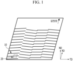
- FIG. 1 shows a schematic view of a grain-oriented electrical steel sheet 10 that is refined with a magnetic domain according to an embodiment of the present invention.
- the grain-oriented electrical steel sheet 10 includes a groove 20 of a line shape formed in a direction crossing a rolled direction (an RD direction) on one surface or both surfaces of the electrical steel sheet.
- a cold-rolled plate is manufactured.
- the cold-rolled plate used in the field of the grain-oriented electrical steel sheet may be used without limitation as a cold-rolled plate to be subjected to the magnetic domain refining.
- the effect of the present invention is expressed regardless of the alloy composition of the grain-oriented electrical steel sheet. Accordingly, the detailed description for the alloy composition of the grain-oriented electrical steel sheet is omitted.
- the cold-rolled plate may include, as wt%, C: 0.10 % or less, Si: 2.0 to 6.5 %, Mn: 0.005 to 1.0 %, Nb+V+Ti: 0.02 % or less, Cr+Sn: 0.8 % or less, Al 3.0 % or less, P+S: 0.09 % or less, and a total amount of a rare earth and other impurities is 0.5 % or less, and the remainder Fe.
- a cold-rolled plate manufacturing method used in the field of the grain-oriented electrical steel sheet may be used without limitation and the detailed description is omitted.
- two to ten grooves may be formed intermittently in the rolled vertical direction.
- FIG. 1 shows an example that four grooves are formed intermittently in the rolled vertical direction.
- the length direction (the RD direction of FIG. 1 , the X direction of FIG. 2 ) of the groove 20 and the rolled direction (the RD direction) may form an angle of 75 to 88°.
- the groove 20 When the groove 20 is formed at the above-described angle, it may contribute to improving the iron loss of the grain-oriented electrical steel sheet.
- the width W of the groove may be 10 to 200 ⁇ m. If the width of groove 20 is smaller or larger than this, it may not be possible to obtain an appropriate magnetic domain refining effect.
- a depth H of the groove may be 30 ⁇ m or less. If the depth H of the groove is too deep, the structural characteristic of the steel sheet 10 may be greatly changed due to the strong laser irradiation, or a large amount of a heel-up and spatter may be formed, thereby deteriorating the magnetism. Therefore, the depth of groove 20 may be controlled within the above-described range. In detail, the depth of the groove may be 3 to 30 ⁇ m.
- a laser or plasma may be irradiated to the cold-rolled plate to form the groove.
- the laser output is 1.5 kW or more
- the laser scanning speed is 8 m/s or more
- the laser scanning distance may be 100 mm or more
- the re-solidification layer may be properly formed under the groove. This leads to the content of the components in the surface layer after the primary recrystallization annealing, and ultimately helps to improve the iron loss. More specifically, the laser output may be 1.5 to 10 kW, the laser scanning speed may be 8 to 15 m/s, and the laser scanning distance may be 100 to 200 mm.
- a laser oscillation method may be used without limitation. That is, continuous oscillation or a pulsed mode may be used. In this way, the laser is irradiated so that the surface beam absorption rate may be more than fusion heat of the steel sheet, and the groove 20 represented in FIG. 1 and FIG. 2 is formed.
- the X direction in FIG. 2 represents the length direction of the groove 20.
- the re-solidification layer is formed under the groove by the heat emitted from the laser or the plasma.
- the re-solidification layer is distinguished by the difference in the overall structure and the grain size of the electrical steel sheet during manufacture.
- the thickness of the re-solidification layer is formed to be 3 ⁇ m or less. If the thickness of the re-solidification layer is too thick, it may affect the weight ratio of SiO 2 /Fe x SiO y of the surface layer part of the cold-rolled plate to be described later, so that the magnetism may be deteriorated. In detail, the thickness of the re-solidification layer may be 0.1 to 3 ⁇ m.
- a step of removing the spatter or heel-up formed on the cold-rolled plate surface may be further included.
- the cold-rolled plate is annealed through primary recrystallization.
- the primary recrystallization annealing process may include decarburization, or decarburization and nitridation, and the annealing may be performed in a humid atmosphere for decarburization, or decarburization and nitridation.
- the soaking temperature at the stage of the primary recrystallization annealing may be 710 to 870 °C. Also, the dew point temperature may be 40 to 70 °C.
- the iron loss may be improved.
- the weight ratio of SiO 2 /Fe x SiO y of the surface layer part of the cold-rolled plate may be 0.3 to 3. If it is out of the above range, a large number of islands are generated in the lower part of the groove after the secondary recrystallization annealing, which may adversely affect the magnetism.
- the surface layer part means the thickness to 1 to 2 ⁇ m from the steel plate surface.
- the weight ratio of SiO 2 /Fe x SiO y may be measured by an FT-IR method.
- an annealing separator is applied, and the secondary recrystallization annealing is performed. Since the annealing separator is widely known, a detailed description is omitted. As an example, an annealing separator having MgO as a main component may be used.
- the purpose of the secondary recrystallization annealing is forming ⁇ 110 ⁇ 001> texture by the secondary recrystallization, providing insulation by forming a metal oxide (vitreous) film by the reaction of the oxide layer formed during primary recrystallization annealing and MgO, and removal of impurities that harm the magnetic characteristics.
- a mixed gas of nitrogen and hydrogen is maintained to protect a nitride as a particle growth suppressor, so that the secondary recrystallization may be developed well, and after the secondary recrystallization is completed, in the soaking step, a 100 % hydrogen atmosphere is maintained for a long time to remove the impurities.
- the secondary recrystallization annealing may be performed in the soaking temperature of 900 to 1210 °C.
- the MgO component in the annealing separator may react with the oxide layer formed on the surface of the steel plate to form a metal oxide layer (a forsterite layer) on the surface of the steel plate and the groove.
- a metal oxide layer a forsterite layer
- the metal oxide layer 30 is represented schematically.
- the metal oxide layer 30 since the groove is formed before the secondary recrystallization annealing, the metal oxide layer 30 may be formed on the surface of the groove as well as the steel plate.
- MgO in the annealing separator penetrates or passes through the inside of the steel plate, thereby forming the island 40 under the metal oxide layer 30.
- This island 40 includes the metal oxide. More specifically, the forsterite is included.
- the island 40 is represented schematically. As shown in FIG. 3 , the island 40 may be formed while separating from the metal oxide layer 30.
- FIG. 3 shows an example in which three islands 40 are formed in the lower part of the groove. That is, the density is three per groove.
- the island 40 has a density of 3 to 15 per groove. More specifically, it may be 10 to 15 pieces.
- the density of the islands positioned under the groove is less than 0.5/ ⁇ m 2 .
- a standard means the density of the islands per groove for the area within 5 ⁇ m under the groove in the cross-section (a TD plane) including the rolled direction (the RD direction) and the thickness direction (the ND direction) of the steel sheet.
- the number of islands with sphericity (a short axis/a long axis) of 0.6 to 1.0 is 60 % or more.
- the standard is the cross-section (the TD surface) including the steel sheet rolled direction (the RD direction) and the thickness direction (the ND direction).
- the island 40 positioned below the surface where the groove 20 is not formed is excluded from the above-mentioned distribution calculation.
- the islands with sphericity (a short axis/a long axis) of 0.6 or less among the islands 40 positioned under the groove 20 is less than 30 %.
- the islands with sphericity (a short axis/a long axis) 0.6 to 1.0 among the islands 40 positioned under the groove 20 is 60 to 90 %. More specifically, the islands with sphericity (a short axis/a long axis) 0.6 to 1.0 among the islands 40 positioned under the groove 20 is 70 to 80 %.
- forming an insulating coating layer on the metal oxide layer may be further included.
- a method of forming the insulating coating layer may be used without particular limitation, and, for example, the insulating coating layer may be formed by applying an insulating coating solution containing a phosphate. It is preferable to use a coating solution including colloidal silica and a metal phosphate as the insulating coating solution.
- the metal phosphate may be Al phosphate, Mg phosphate, or a combination thereof, and the content of Al, Mg, or a combination thereof relative to the weight of the insulating coating solution may be 15 wt% or more.
- the grain-oriented electrical steel sheet according to an embodiment of the present invention includes the groove 20 positioned at the surface of the electrical steel sheet 10, the metal oxide layer 30 positioned on the groove 20, and the island 40 positioned under the groove.
- a cold-rolled plate with a thickness of 0.23 mm was prepared. This cold-rolled plate was irradiated with a continuous wave laser of A 2.0k W Gaussian mode at a scanning speed of 10 m/s and a scanning distance of 150 mm to form a groove at an angle of 85° with the RD direction. After that, the primary recrystallization annealing was carried out, and the secondary recrystallization was performed after applying a MgO annealing separator. After that, an insulating coating layer was formed.
- the weight ratio of SiO 2 /Fe x SiO y on the surface part was measured and is shown in Table 1, and the island density at the lower part of the groove was measured and is shown in Table 1.
- the iron loss (W17/50) was measured and is shown in Table 1 below.
- the number of the islands having sphericity of 0.6 to 1.0 among the islands positioned in the lower part of the groove is 50 % or more, respectively, and the density of the islands positioned in the lower part of the groove is 15 or less.
- the number of the islands with sphericity of 0.6 to 1.0 among the islands positioned under the groove is less than 50 %, and the density of the islands positioned under the groove exceeds 15.
Landscapes
- Chemical & Material Sciences (AREA)
- Engineering & Computer Science (AREA)
- Physics & Mathematics (AREA)
- Mechanical Engineering (AREA)
- Metallurgy (AREA)
- Materials Engineering (AREA)
- Organic Chemistry (AREA)
- Thermal Sciences (AREA)
- Crystallography & Structural Chemistry (AREA)
- Manufacturing & Machinery (AREA)
- Electromagnetism (AREA)
- Power Engineering (AREA)
- Optics & Photonics (AREA)
- Dispersion Chemistry (AREA)
- Chemical Kinetics & Catalysis (AREA)
- Plasma & Fusion (AREA)
- Soft Magnetic Materials (AREA)
- Manufacturing Of Steel Electrode Plates (AREA)
Claims (7)
- Tôle d'acier électrique à grains orientés (10) comprenant :une rainure (20) positionnée dans une surface d'une surface de tôle d'acier électrique dans une direction croisant une direction de laminage ;une couche d'oxyde métallique (30) positionnée sur la rainure ; etun îlot à base d'oxyde métallique (40) à répartition discontinue positionné sous la rainure,caractérisée en ce que la densité des îlots positionnés sous la rainure est de 3 à 15 par rainure, dans laquelle la densité des îlots positionnés sous la rainure est de 0,5 pièce/µm2 ou moins.
- Tôle d'acier électrique à grains orientés selon la revendication 1, dans laquelle :
parmi les îlots positionnés sous la rainure, le nombre d'îlots ayant une sphéricité de 0,6 à 1,0 est de 60 % ou plus. - Tôle d'acier électrique à grains orientés selon la revendication 1, dans laquelle :
les rainures sont formées par intermittence entre 2 et 10. - Tôle d'acier électrique à grains orientés selon la revendication 1, dans laquelle :
la direction de longueur de la rainure et la direction de laminage de la tôle d'acier forment un angle de 75 à 88°. - Procédé de fabrication d'une tôle d'acier électrique à grains orientés selon l'une quelconque des revendications 1 à 4, (10) comprenant :la production d'une plaque laminée à froid ;la formation d'une rainure (20) dans la plaque laminée à froid, dans une direction croisant une direction de laminage ;la réalisation d'un recuit de recristallisation primaire sur la plaque laminée à froid présentant une rainure formée ; etl'application d'un séparateur de recuit à la plaque laminée à froid ayant subi une recristallisation primaire et la réalisation d'un recuit de recristallisation secondaire,dans lequel un rapport de poids de SiO2/FexSiOy de la partie de couche de surface de la plaque laminée à froid est de 0,3 à 3 après le recuit de recristallisation primaire de la plaque laminée à froid,où x est un nombre entier de 1 à 2, et y est un nombre entier de 2 à 4,dans lequel :
lors de la formation de la rainure, une couche de resolidification est formée sous la rainure, dans lequel :
lors de la formation de la rainure, une couche de resolidification est formée avec une épaisseur de 3 µm ou moins sous la rainure. - Procédé de fabrication de la tôle d'acier électrique à grains orientés selon la revendication 5, dans lequel :lors de la formation de la rainure, un laser est irradié sur la plaque laminée à froid pour former la rainure,une sortie laser est de 1,5 kW ou plus, une vitesse de balayage laser est de 8 m/s ou plus, et une distance de balayage laser est de 100 mm ou plus.
- Procédé de fabrication de la tôle d'acier électrique à grains orientés selon la revendication 5, dans lequel :
le recuit de recristallisation primaire de la plaque laminée à froid est réalisé à une température de 710 à 870 °C et à une température de point de rosée de 40 à 70 °C dans une atmosphère humide pour une décarburation ou une décarburation et une nitruration.
Applications Claiming Priority (2)
| Application Number | Priority Date | Filing Date | Title |
|---|---|---|---|
| KR1020180165644A KR102149826B1 (ko) | 2018-12-19 | 2018-12-19 | 방향성 전기강판 및 그의 제조 방법 |
| PCT/KR2019/018025 WO2020130639A1 (fr) | 2018-12-19 | 2019-12-18 | Tôle d'acier électrique à grains orientés et son procédé de fabrication |
Publications (4)
| Publication Number | Publication Date |
|---|---|
| EP3901970A1 EP3901970A1 (fr) | 2021-10-27 |
| EP3901970A4 EP3901970A4 (fr) | 2022-03-09 |
| EP3901970B1 true EP3901970B1 (fr) | 2025-03-05 |
| EP3901970C0 EP3901970C0 (fr) | 2025-03-05 |
Family
ID=71102203
Family Applications (1)
| Application Number | Title | Priority Date | Filing Date |
|---|---|---|---|
| EP19898832.1A Active EP3901970B1 (fr) | 2018-12-19 | 2019-12-18 | Tôle d'acier électrique à grains orientés et son procédé de fabrication |
Country Status (5)
| Country | Link |
|---|---|
| EP (1) | EP3901970B1 (fr) |
| JP (1) | JP7365416B2 (fr) |
| KR (1) | KR102149826B1 (fr) |
| CN (1) | CN113243034B (fr) |
| WO (1) | WO2020130639A1 (fr) |
Families Citing this family (1)
| Publication number | Priority date | Publication date | Assignee | Title |
|---|---|---|---|---|
| KR102133910B1 (ko) | 2018-12-19 | 2020-07-14 | 주식회사 포스코 | 방향성 전기강판 및 그의 제조 방법 |
Family Cites Families (16)
| Publication number | Priority date | Publication date | Assignee | Title |
|---|---|---|---|---|
| JPS5234222B2 (fr) * | 1972-02-04 | 1977-09-02 | ||
| GB2208871B (en) * | 1987-08-22 | 1991-03-27 | British Steel Plc | Processing grain-oriented "electrical" steel |
| JP4276547B2 (ja) * | 2003-01-15 | 2009-06-10 | 新日本製鐵株式会社 | 高磁場鉄損と被膜特性に優れる超高磁束密度一方向性電磁鋼板 |
| JP2009134009A (ja) * | 2007-11-29 | 2009-06-18 | Ricoh Co Ltd | 現像剤規制部材、現像装置、画像形成装置及びプロセスカートリッジ |
| CN102834529A (zh) * | 2010-04-01 | 2012-12-19 | 新日本制铁株式会社 | 方向性电磁钢板及其制造方法 |
| JP5158285B2 (ja) | 2010-09-09 | 2013-03-06 | 新日鐵住金株式会社 | 方向性電磁鋼板 |
| CN102941413B (zh) * | 2012-11-23 | 2015-07-01 | 武汉钢铁(集团)公司 | 一种取向硅钢多次激光刻槽降低铁损的方法 |
| KR101480498B1 (ko) * | 2012-12-28 | 2015-01-08 | 주식회사 포스코 | 방향성 전기강판 및 그 제조방법 |
| KR102240346B1 (ko) | 2013-02-08 | 2021-04-14 | 닛폰세이테츠 가부시키가이샤 | 절연 코팅을 형성하기 위한 용액 및 방향성 전기 강 시트 |
| WO2015012562A1 (fr) | 2013-07-24 | 2015-01-29 | 주식회사 포스코 | Tôle d'acier au four électrique orientée et procédé pour la fabrication de celle-ci |
| KR101594598B1 (ko) * | 2013-12-23 | 2016-02-16 | 주식회사 포스코 | 방향성 전기강판 제조방법 |
| KR101719231B1 (ko) * | 2014-12-24 | 2017-04-04 | 주식회사 포스코 | 방향성 전기강판 및 그 제조방법 |
| KR101693516B1 (ko) | 2014-12-24 | 2017-01-06 | 주식회사 포스코 | 방향성 전기강판 및 그 제조방법 |
| JP6168173B2 (ja) | 2015-01-30 | 2017-07-26 | Jfeスチール株式会社 | 方向性電磁鋼板とその製造方法 |
| JP6657837B2 (ja) | 2015-11-19 | 2020-03-04 | 日本製鉄株式会社 | 方向性電磁鋼板およびその製造方法 |
| KR101884429B1 (ko) * | 2016-12-22 | 2018-08-01 | 주식회사 포스코 | 방향성 전기강판 및 그 자구미세화 방법 |
-
2018
- 2018-12-19 KR KR1020180165644A patent/KR102149826B1/ko active Active
-
2019
- 2019-12-18 JP JP2021536313A patent/JP7365416B2/ja not_active Ceased
- 2019-12-18 WO PCT/KR2019/018025 patent/WO2020130639A1/fr not_active Ceased
- 2019-12-18 CN CN201980084800.7A patent/CN113243034B/zh active Active
- 2019-12-18 EP EP19898832.1A patent/EP3901970B1/fr active Active
Also Published As
| Publication number | Publication date |
|---|---|
| KR20200076503A (ko) | 2020-06-29 |
| JP7365416B2 (ja) | 2023-10-19 |
| WO2020130639A1 (fr) | 2020-06-25 |
| CN113243034A (zh) | 2021-08-10 |
| CN113243034B (zh) | 2024-06-04 |
| JP2022514795A (ja) | 2022-02-15 |
| EP3901970A1 (fr) | 2021-10-27 |
| EP3901970C0 (fr) | 2025-03-05 |
| KR102149826B1 (ko) | 2020-08-31 |
| EP3901970A4 (fr) | 2022-03-09 |
| US20220051836A1 (en) | 2022-02-17 |
Similar Documents
| Publication | Publication Date | Title |
|---|---|---|
| US11772199B2 (en) | Grain-oriented electrical steel sheet and magnetic domain refinement method therefor | |
| KR101719231B1 (ko) | 방향성 전기강판 및 그 제조방법 | |
| KR102133909B1 (ko) | 방향성 전기강판 및 그의 제조 방법 | |
| JP7561194B2 (ja) | 方向性電磁鋼板およびその磁区微細化方法 | |
| CN120344680A (zh) | 取向电钢板及其制造方法 | |
| EP3901970B1 (fr) | Tôle d'acier électrique à grains orientés et son procédé de fabrication | |
| EP3901969B1 (fr) | Tôle d'acier électrique orientée et son procédé de production | |
| US12620513B2 (en) | Oriented electrical steel sheet and method for manufacturing same | |
| KR20240098941A (ko) | 방향성 전기강판 및 그 제조방법 |
Legal Events
| Date | Code | Title | Description |
|---|---|---|---|
| STAA | Information on the status of an ep patent application or granted ep patent |
Free format text: STATUS: THE INTERNATIONAL PUBLICATION HAS BEEN MADE |
|
| PUAI | Public reference made under article 153(3) epc to a published international application that has entered the european phase |
Free format text: ORIGINAL CODE: 0009012 |
|
| STAA | Information on the status of an ep patent application or granted ep patent |
Free format text: STATUS: REQUEST FOR EXAMINATION WAS MADE |
|
| 17P | Request for examination filed |
Effective date: 20210701 |
|
| AK | Designated contracting states |
Kind code of ref document: A1 Designated state(s): AL AT BE BG CH CY CZ DE DK EE ES FI FR GB GR HR HU IE IS IT LI LT LU LV MC MK MT NL NO PL PT RO RS SE SI SK SM TR |
|
| REG | Reference to a national code |
Ref country code: DE Ref legal event code: R079 Free format text: PREVIOUS MAIN CLASS: H01F0001160000 Ipc: H01F0001180000 Ref country code: DE Ref legal event code: R079 Ref document number: 602019067045 Country of ref document: DE Free format text: PREVIOUS MAIN CLASS: H01F0001160000 Ipc: H01F0001180000 |
|
| A4 | Supplementary search report drawn up and despatched |
Effective date: 20220203 |
|
| RIC1 | Information provided on ipc code assigned before grant |
Ipc: C21D 10/00 20060101ALI20220128BHEP Ipc: C21D 8/12 20060101ALI20220128BHEP Ipc: H01F 41/02 20060101ALI20220128BHEP Ipc: H01F 1/18 20060101AFI20220128BHEP |
|
| DAV | Request for validation of the european patent (deleted) | ||
| DAX | Request for extension of the european patent (deleted) | ||
| RAP3 | Party data changed (applicant data changed or rights of an application transferred) |
Owner name: POSCO HOLDINGS INC. |
|
| RAP1 | Party data changed (applicant data changed or rights of an application transferred) |
Owner name: POSCO CO., LTD |
|
| GRAP | Despatch of communication of intention to grant a patent |
Free format text: ORIGINAL CODE: EPIDOSNIGR1 |
|
| STAA | Information on the status of an ep patent application or granted ep patent |
Free format text: STATUS: GRANT OF PATENT IS INTENDED |
|
| INTG | Intention to grant announced |
Effective date: 20241023 |
|
| GRAS | Grant fee paid |
Free format text: ORIGINAL CODE: EPIDOSNIGR3 |
|
| GRAA | (expected) grant |
Free format text: ORIGINAL CODE: 0009210 |
|
| STAA | Information on the status of an ep patent application or granted ep patent |
Free format text: STATUS: THE PATENT HAS BEEN GRANTED |
|
| AK | Designated contracting states |
Kind code of ref document: B1 Designated state(s): AL AT BE BG CH CY CZ DE DK EE ES FI FR GB GR HR HU IE IS IT LI LT LU LV MC MK MT NL NO PL PT RO RS SE SI SK SM TR |
|
| REG | Reference to a national code |
Ref country code: GB Ref legal event code: FG4D |
|
| REG | Reference to a national code |
Ref country code: CH Ref legal event code: EP |
|
| REG | Reference to a national code |
Ref country code: DE Ref legal event code: R096 Ref document number: 602019067045 Country of ref document: DE |
|
| REG | Reference to a national code |
Ref country code: IE Ref legal event code: FG4D |
|
| U01 | Request for unitary effect filed |
Effective date: 20250319 |
|
| U07 | Unitary effect registered |
Designated state(s): AT BE BG DE DK EE FI FR IT LT LU LV MT NL PT RO SE SI Effective date: 20250325 |
|
| PG25 | Lapsed in a contracting state [announced via postgrant information from national office to epo] |
Ref country code: RS Free format text: LAPSE BECAUSE OF FAILURE TO SUBMIT A TRANSLATION OF THE DESCRIPTION OR TO PAY THE FEE WITHIN THE PRESCRIBED TIME-LIMIT Effective date: 20250605 |
|
| PG25 | Lapsed in a contracting state [announced via postgrant information from national office to epo] |
Ref country code: ES Free format text: LAPSE BECAUSE OF FAILURE TO SUBMIT A TRANSLATION OF THE DESCRIPTION OR TO PAY THE FEE WITHIN THE PRESCRIBED TIME-LIMIT Effective date: 20250305 |
|
| PG25 | Lapsed in a contracting state [announced via postgrant information from national office to epo] |
Ref country code: NO Free format text: LAPSE BECAUSE OF FAILURE TO SUBMIT A TRANSLATION OF THE DESCRIPTION OR TO PAY THE FEE WITHIN THE PRESCRIBED TIME-LIMIT Effective date: 20250605 |
|
| PG25 | Lapsed in a contracting state [announced via postgrant information from national office to epo] |
Ref country code: HR Free format text: LAPSE BECAUSE OF FAILURE TO SUBMIT A TRANSLATION OF THE DESCRIPTION OR TO PAY THE FEE WITHIN THE PRESCRIBED TIME-LIMIT Effective date: 20250305 |
|
| PG25 | Lapsed in a contracting state [announced via postgrant information from national office to epo] |
Ref country code: GR Free format text: LAPSE BECAUSE OF FAILURE TO SUBMIT A TRANSLATION OF THE DESCRIPTION OR TO PAY THE FEE WITHIN THE PRESCRIBED TIME-LIMIT Effective date: 20250606 |
|
| PG25 | Lapsed in a contracting state [announced via postgrant information from national office to epo] |
Ref country code: SM Free format text: LAPSE BECAUSE OF FAILURE TO SUBMIT A TRANSLATION OF THE DESCRIPTION OR TO PAY THE FEE WITHIN THE PRESCRIBED TIME-LIMIT Effective date: 20250305 |
|
| PG25 | Lapsed in a contracting state [announced via postgrant information from national office to epo] |
Ref country code: PL Free format text: LAPSE BECAUSE OF FAILURE TO SUBMIT A TRANSLATION OF THE DESCRIPTION OR TO PAY THE FEE WITHIN THE PRESCRIBED TIME-LIMIT Effective date: 20250305 |
|
| PG25 | Lapsed in a contracting state [announced via postgrant information from national office to epo] |
Ref country code: CZ Free format text: LAPSE BECAUSE OF FAILURE TO SUBMIT A TRANSLATION OF THE DESCRIPTION OR TO PAY THE FEE WITHIN THE PRESCRIBED TIME-LIMIT Effective date: 20250305 |
|
| PG25 | Lapsed in a contracting state [announced via postgrant information from national office to epo] |
Ref country code: SK Free format text: LAPSE BECAUSE OF FAILURE TO SUBMIT A TRANSLATION OF THE DESCRIPTION OR TO PAY THE FEE WITHIN THE PRESCRIBED TIME-LIMIT Effective date: 20250305 |
|
| PG25 | Lapsed in a contracting state [announced via postgrant information from national office to epo] |
Ref country code: IS Free format text: LAPSE BECAUSE OF FAILURE TO SUBMIT A TRANSLATION OF THE DESCRIPTION OR TO PAY THE FEE WITHIN THE PRESCRIBED TIME-LIMIT Effective date: 20250705 |
|
| PLBE | No opposition filed within time limit |
Free format text: ORIGINAL CODE: 0009261 |
|
| STAA | Information on the status of an ep patent application or granted ep patent |
Free format text: STATUS: NO OPPOSITION FILED WITHIN TIME LIMIT |
|
| REG | Reference to a national code |
Ref country code: CH Ref legal event code: L10 Free format text: ST27 STATUS EVENT CODE: U-0-0-L10-L00 (AS PROVIDED BY THE NATIONAL OFFICE) Effective date: 20260114 |
|
| U20 | Renewal fee for the european patent with unitary effect paid |
Year of fee payment: 7 Effective date: 20251223 |
|
| 26N | No opposition filed |
Effective date: 20251208 |