EP3902135B1 - Winkelpositionsfehlerschätzung im stillstand für hochfrequenzspannungsinjektion - Google Patents
Winkelpositionsfehlerschätzung im stillstand für hochfrequenzspannungsinjektion Download PDFInfo
- Publication number
- EP3902135B1 EP3902135B1 EP20170391.5A EP20170391A EP3902135B1 EP 3902135 B1 EP3902135 B1 EP 3902135B1 EP 20170391 A EP20170391 A EP 20170391A EP 3902135 B1 EP3902135 B1 EP 3902135B1
- Authority
- EP
- European Patent Office
- Prior art keywords
- angular position
- torque
- signal
- synchronous motor
- est
- Prior art date
- Legal status (The legal status is an assumption and is not a legal conclusion. Google has not performed a legal analysis and makes no representation as to the accuracy of the status listed.)
- Active
Links
Images


Classifications
-
- H—ELECTRICITY
- H02—GENERATION; CONVERSION OR DISTRIBUTION OF ELECTRIC POWER
- H02P—CONTROL OR REGULATION OF ELECTRIC MOTORS, ELECTRIC GENERATORS OR DYNAMO-ELECTRIC CONVERTERS; CONTROLLING TRANSFORMERS, REACTORS OR CHOKE COILS
- H02P21/00—Arrangements or methods for the control of electric machines by vector control, e.g. by control of field orientation
- H02P21/14—Estimation or adaptation of machine parameters, e.g. flux, current or voltage
- H02P21/18—Estimation of position or speed
-
- H—ELECTRICITY
- H02—GENERATION; CONVERSION OR DISTRIBUTION OF ELECTRIC POWER
- H02P—CONTROL OR REGULATION OF ELECTRIC MOTORS, ELECTRIC GENERATORS OR DYNAMO-ELECTRIC CONVERTERS; CONTROLLING TRANSFORMERS, REACTORS OR CHOKE COILS
- H02P6/00—Arrangements for controlling synchronous motors or other dynamo-electric motors using electronic commutation dependent on the rotor position; Electronic commutators therefor
- H02P6/14—Electronic commutators
- H02P6/16—Circuit arrangements for detecting position
- H02P6/18—Circuit arrangements for detecting position without separate position detecting elements
- H02P6/183—Circuit arrangements for detecting position without separate position detecting elements using an injected high frequency signal
-
- H—ELECTRICITY
- H02—GENERATION; CONVERSION OR DISTRIBUTION OF ELECTRIC POWER
- H02P—CONTROL OR REGULATION OF ELECTRIC MOTORS, ELECTRIC GENERATORS OR DYNAMO-ELECTRIC CONVERTERS; CONTROLLING TRANSFORMERS, REACTORS OR CHOKE COILS
- H02P21/00—Arrangements or methods for the control of electric machines by vector control, e.g. by control of field orientation
- H02P21/14—Estimation or adaptation of machine parameters, e.g. flux, current or voltage
-
- H—ELECTRICITY
- H02—GENERATION; CONVERSION OR DISTRIBUTION OF ELECTRIC POWER
- H02P—CONTROL OR REGULATION OF ELECTRIC MOTORS, ELECTRIC GENERATORS OR DYNAMO-ELECTRIC CONVERTERS; CONTROLLING TRANSFORMERS, REACTORS OR CHOKE COILS
- H02P21/00—Arrangements or methods for the control of electric machines by vector control, e.g. by control of field orientation
- H02P21/0003—Control strategies in general, e.g. linear type, e.g. P, PI, PID, using robust control
- H02P21/0025—Control strategies in general, e.g. linear type, e.g. P, PI, PID, using robust control implementing a off line learning phase to determine and store useful data for on-line control
-
- H—ELECTRICITY
- H02—GENERATION; CONVERSION OR DISTRIBUTION OF ELECTRIC POWER
- H02P—CONTROL OR REGULATION OF ELECTRIC MOTORS, ELECTRIC GENERATORS OR DYNAMO-ELECTRIC CONVERTERS; CONTROLLING TRANSFORMERS, REACTORS OR CHOKE COILS
- H02P21/00—Arrangements or methods for the control of electric machines by vector control, e.g. by control of field orientation
- H02P21/14—Estimation or adaptation of machine parameters, e.g. flux, current or voltage
- H02P21/20—Estimation of torque
-
- H—ELECTRICITY
- H02—GENERATION; CONVERSION OR DISTRIBUTION OF ELECTRIC POWER
- H02P—CONTROL OR REGULATION OF ELECTRIC MOTORS, ELECTRIC GENERATORS OR DYNAMO-ELECTRIC CONVERTERS; CONTROLLING TRANSFORMERS, REACTORS OR CHOKE COILS
- H02P21/00—Arrangements or methods for the control of electric machines by vector control, e.g. by control of field orientation
- H02P21/22—Current control, e.g. using a current control loop
-
- H—ELECTRICITY
- H02—GENERATION; CONVERSION OR DISTRIBUTION OF ELECTRIC POWER
- H02P—CONTROL OR REGULATION OF ELECTRIC MOTORS, ELECTRIC GENERATORS OR DYNAMO-ELECTRIC CONVERTERS; CONTROLLING TRANSFORMERS, REACTORS OR CHOKE COILS
- H02P21/00—Arrangements or methods for the control of electric machines by vector control, e.g. by control of field orientation
- H02P21/24—Vector control not involving the use of rotor position or rotor speed sensors
-
- H—ELECTRICITY
- H02—GENERATION; CONVERSION OR DISTRIBUTION OF ELECTRIC POWER
- H02P—CONTROL OR REGULATION OF ELECTRIC MOTORS, ELECTRIC GENERATORS OR DYNAMO-ELECTRIC CONVERTERS; CONTROLLING TRANSFORMERS, REACTORS OR CHOKE COILS
- H02P25/00—Arrangements or methods for the control of AC motors characterised by the kind of AC motor or by structural details
- H02P25/02—Arrangements or methods for the control of AC motors characterised by the kind of AC motor or by structural details characterised by the kind of motor
- H02P25/022—Synchronous motors
-
- H—ELECTRICITY
- H02—GENERATION; CONVERSION OR DISTRIBUTION OF ELECTRIC POWER
- H02P—CONTROL OR REGULATION OF ELECTRIC MOTORS, ELECTRIC GENERATORS OR DYNAMO-ELECTRIC CONVERTERS; CONTROLLING TRANSFORMERS, REACTORS OR CHOKE COILS
- H02P2203/00—Indexing scheme relating to controlling arrangements characterised by the means for detecting the position of the rotor
- H02P2203/11—Determination or estimation of the rotor position or other motor parameters based on the analysis of high-frequency signals
-
- H—ELECTRICITY
- H02—GENERATION; CONVERSION OR DISTRIBUTION OF ELECTRIC POWER
- H02P—CONTROL OR REGULATION OF ELECTRIC MOTORS, ELECTRIC GENERATORS OR DYNAMO-ELECTRIC CONVERTERS; CONTROLLING TRANSFORMERS, REACTORS OR CHOKE COILS
- H02P2207/00—Indexing scheme relating to controlling arrangements characterised by the type of motor
- H02P2207/05—Synchronous machines, e.g. with permanent magnets or DC excitation
Definitions
- Various example embodiments relate to control of industrial processes, in particular to an apparatus and to a method to estimate angular position error of a synchronous motor and to operate said synchronous motor.
- the rotation of the motor shaft i.e., of the rotor
- AC alternating current
- One common way for controlling synchronous electric motors is the so-called vector control where the torque of the motor is controlled by controlling a stator current vector.
- the angular position of the rotor needs to be estimated (e.g., using voltage injection). This estimation is mainly dependent on the saliency of the motor.
- One of the main challenges for any saliency-based sensorless method is overcoming the error introduced by differential cross coupling between the d- and q-axes in the rotating reference frame.
- US 10 224 851 B2 discloses a system and a method for sensorless control of electric machines using magnetic alignment signatures.
- WO 00/25418 A1 discloses a system and a method for speed-sensorless control of an induction machine.
- SILVERIO BOLOGNANI ET AL "Sensorless quasi-standstill and very low-speed position detection in non-salient PMSMs based on current injection and back-EMF observer”
- SENSORLESS CONTROL FOR ELECTRICAL DRIVES (SLED) 2012 IEEE SYMPOSIUM ON, IEEE, 21 September 2012 (2012-09-21), pages 1-7, P032322100, DOI: 10.1109/SLED.2012.6422813, ISBN: 978-1-4673-2966-8 discloses methods for position detection of a permanent magnet synchronous motor based on the detection of torque production by signal injection.
- two different application cases are disclosed: an initial high-accuracy position detection at quasi-standstill and a position and speed tracking for closed-
- Some embodiments provide an apparatus, a method, and computer readable media for performing angular position error estimation for a synchronous motor.
- stator current/voltage vector is a vector comprising two orthogonal stator current/voltage components derived from stator currents/voltages of a three-phase AC electric machine. One of said components defines the magnetic flux of the motor, the other the torque of the motor.
- stator current/voltage components may be written either in a stationary reference frame as ⁇ - and ⁇ -axis stator currents/voltages or in a moving reference frame (moving in sync with the rotor) as d- and q-axis stator currents/voltages, respectively.
- the actual control in the vector control is typically performed for the d - and q -axis stator currents or voltages while the ⁇ - and ⁇ -axis stator currents or voltages are used for actually driving the synchronous motor.
- the d - and q -axis currents/voltages may be converted to the ⁇ - and ⁇ -axis currents/voltages using inverse Park transform while an opposite transformation is possible using Park transform.
- u d u q u d h cos ⁇ h t 0
- u d h an amplitude of the d -axis stator voltage signal
- ⁇ h the (high) angular frequency of the d -axis voltage signal
- ⁇ ⁇ q h 0
- the embodiments provide a solution enabling accurate evaluation of the position error without a position sensor and without (substantially) rotating the synchronous motor.
- the synchronous motor 111 may be running an industrial or non-industrial process, for example, a system for transporting material, such as a pump, a fan, a compressor, a blower, a conveyor belt, a crane and/or an elevator and/or a system for processing materials, such as a paper machine, a mill, a stirrer and/or a centrifuge.
- a system for transporting material such as a pump, a fan, a compressor, a blower, a conveyor belt, a crane and/or an elevator and/or a system for processing materials, such as a paper machine, a mill, a stirrer and/or a centrifuge.
- the illustrated system is based on (sensorless) vector control with high-frequency voltage injection. Any of elements 101 to 110, 112 to 124 may be logical elements implemented as hardware or software or a combination thereof.
- the ⁇ ⁇ estimator state machine may maintain, in a database, only information on one or more pre-defined pulsating torque signals, each of which corresponds to a particular torque operating point (i.e., a particular torque level).
- the goal of the angular position error estimation procedure to be discussed below is to gather information on the error in the estimated angular position of the rotor of the synchronous motor 111 (as estimated by the illustrated system using high-frequency voltage injection) at one or more torque operating points by operating the synchronous motor 111 according to each of the one or more pre-defined pulsating torque signals in sequence.
- the one or more torque operating points comprises a plurality of torque operating points and cover the whole operational range of the synchronous motor 111.
- Each of the one or more pre-defined pulsating torque signals defined in the database of the ⁇ ⁇ estimator state machine 101 may comprise one or more positive pulses (e.g., positive square pulses) and one or more negative pulses (e.g., negative square pulses). Each of said one or more positive pulses have preferably the same peak amplitude. A peak amplitude of each pre-defined pulsating torque signal corresponds to a torque operating point of the synchronous motor. Further, each pre-defined pulsating torque signal has a zero mean so that the total movement of the rotor of the synchronous motor 111 when the synchronous motor 111 is driven according to the pre-defined pulsating torque signal is minimized.
- the initial angular position of the rotor before the application of the pre-defined pulsating torque signal should be approximately the same as the final angular position of the rotor following the application of the pre-defined pulsating torque signal.
- said one or more positive pulses and said one or more negative pulses should also be arranged in such a manner that the total movement of the rotor caused by the application of the pre-defined pulsating torque signal is minimized.
- the pre-defined pulsating torque signal may, for example, consist of a first positive (square) pulse having a first duration t step , a negative (square) pulse having a second duration 2 t step (i.e., being twice the first duration) and a second positive (square) pulse having the first duration t step .
- These three pulses may be in the described order (or in some other order) and/or they may or may not directly follow each other (i.e., there is zero or non-zero time separation between consecutive pulses). All three pulses may have the same peak amplitude.
- Figure 2 One such example of a pre-defined pulsating torque signal is shown in Figure 2 (to be discussed in detail below).
- the pre-defined pulsating torque signal may, in other embodiments, consist of a first negative (square) pulse, a negative (square) pulse, a second positive (square) pulse and a second negative (square) pulse in this order, where each pulse has the same duration. Any of the consecutive pulses may or may not directly follow each other also in this embodiment.
- the synchronous motor 111 is operated according to the pre-defined pulsating torque signal corresponding to said torque operating point using a sensorless vector control method employing high-frequency voltage injection (i.e., using elements 101 to 110, 112 to 124).
- the pre-defined pulsating torque signal T ref ( n ) produced by the ⁇ ⁇ estimator state machine 101 is processed in a maximum torque per ampere (MTPA) element 102 implementing a MTPA control method to form.
- the MTPA control method produces the desired torque while minimizing current magnitude.
- the MTPA element 102 generates d - and q -axis stator current signals i d ⁇ and i q ⁇ based on the pre-defined pulsating torque pulse signal T ref ( n ) using said MTPA control method.
- other means for converting the pre-defined pulsating torque signal to the d - and q -axis stator current signals may be employed.
- a first difference signal is calculated, in element 103, as a difference between a generated d -axis stator current signal i d ⁇ and a measured d -axis stator current signal i d ′ of the synchronous motor 111.
- a second difference signal is calculated as a difference between a generated q -axis stator current signal i d ⁇ and a measured q -axis stator current signal i q ′ of the synchronous motor 111 also in element 103.
- the first and second difference signals quantify the error between desired stator currents and the actual measured stator currents. How the measured d - and q -axis stator current signals i d ′ and i q ′ are actually measured, in elements 112, 113, is discussed later.
- a d -axis stator voltage signal u d is calculated, by a first proportional-integral (PI) controller 106, based on the first difference signal.
- a q -axis stator voltage signal u q is calculated, also by the PI controller 106, based on the second difference signal.
- the d - and q -axis stator voltage signals u d and u q may be combined (i.e., summed together), in a combining (i.e., summing) element 108, respectively, with first optional d- and q -axis voltage stator signal components, second optional d - and q -axis stator voltage signal components or both.
- the first optional d - and q -axis voltage stator signal components may be calculated by an integral (I) controller 104 fed by the generated d - and q -axis stator current signals i d ⁇ and i q ⁇ and the second optional d - and q -axis voltage stator signal components may be calculated by a proportional (P) controller 105 fed by the generated d - and q -axis stator current signals i d ⁇ and i q ⁇ .
- I integral
- P proportional
- both the first and second optional d - and q -axis voltage stator signal components may be combined in a combining (i.e., summing) element 107 before the resulting signal is combined in the combining element 108 with the d - and q -axis stator voltage signals u d and u q . All of the operations discussed in this paragraph are carried out separately for d -axis signals and for q -axis signals (e.g., d -axis signals are combined only with other d -axis signals and q -axis signals are combined only with other q -axis signals).
- the d - and a q -axis stator voltage signals u d and u q are transformed, in vector rotation (VR) element 109, to ⁇ - and ⁇ -axis stator voltage signals u ⁇ and u ⁇ using inverse Park transform.
- the inverse Park transform requires knowledge of the current angular position (i.e., rotation angle) of the rotor.
- the current angular position may be estimated continuously during the running of the angular position error estimation procedure, as will be described in detail below.
- Said high-frequency ⁇ - and ⁇ -axis stator voltage signals u ⁇ h and u ⁇ h are generated as follows. Initially, a signal generation element 121 in the position estimation unit 124 generates a high-frequency square-wave d -axis stator voltage signal having a frequency larger than a frequency of the pre-defined pulsating torque signal.
- the frequency of the high-frequency square-wave d -axis stator voltage signal should be much larger (e.g., one or more orders of magnitude larger or two or more orders of magnitude larger) than the frequency of the pre-defined pulsating torque signal so that the high-frequency component may be easily isolated, by high-pass filtering, from the main stator voltage/current signals to which it has been inserted.
- the frequency of the high-frequency square-wave d -axis stator voltage signal may be at least larger than the frequency of the pre-defined pulsating torque signal multiplied by ten or one hundred.
- the synchronous motor 111 produces ⁇ - and ⁇ -axis output stator current signals i ⁇ and i ⁇ which may be measured to produce an output. These current signals are used for two different purposes. Firstly, the ⁇ - and ⁇ -axis output stator current signals i ⁇ and i ⁇ are converted, in a vector rotation element 113 using Park transform, to d - and q -axis output stator current signals i d and i q which are subtracted, after taking an average in element 112, from the generated d - and q -axis output stator current signals i d ⁇ and i q ⁇ , respectively.
- the average which may be calculated for each of the d- and q -axis output stator current signals i d and i q in element 112 may be specifically two-sample average.
- the purpose of calculating the average is to eliminate the high-frequency components (i.e., signal components resulting from the voltage injection) from the d - and q -axis stator current signals i d and i q .
- Park transform in element 113 may be calculated based on a previously estimated (or pre-defined) value of the angular position of the rotor maintained in the database of the ⁇ estimator state machine 101.
- the ⁇ - and ⁇ -axis output stator current signals i ⁇ and i ⁇ are used for estimating the angular position of the rotor and the angular speed of the rotor in the position estimation unit 124.
- the ⁇ - and ⁇ -axis output stator current signals i ⁇ and i ⁇ are first converted, in a vector rotation element 114, using Park transform to a q -axis output stator current signal i q .
- Park transform may be calculated based on a previously estimated or pre-defined value of the angular position of the rotor, as will be described in detail below.
- the high-frequency q -axis output stator current signal corresponds, here, to a response of the synchronous motor 111 to the high-frequency square-wave d -axis stator voltage signal fed (or injected) to the synchronous motor 111, i.e., it is the signal component resulting from the voltage injection.
- a product of the high-frequency q -axis output stator voltage component and a signal formed by applying a signum function, in element 120, to the high-frequency square-wave d -axis stator voltage signal is calculated in multiplication element 117.
- the cut-off frequency of the LPF 119 may be defined based on ⁇ t and the response time of the phase-locked loop (PLL) of the position estimation unit 124, where ⁇ t denotes a (pre-defined) time separation of first measurements performed by the system at a first time instance while the pre-defined pulsating torque signal is being applied and subsequent second measurements performed by the system at a second time instance when the pre-defined pulsating torque signal is now longer applied.
- ⁇ t should be as small as possible.
- a plurality of values of the (final) estimated angular speed may be stored to a lookup table maintained in a database of the ⁇ ⁇ estimator state machine 101. Specifically, said plurality of values of the (final) estimated angular speed may comprise one or more of:
- coinciding values of the desired torque may also be measured and stored to the lookup table.
- coinciding values of the desired torque i.e., a value of the pre-defined pulsating torque signal
- the lookup table may also be measured and stored to the lookup table.
- the above calculation of the error in the estimated angular position only employs measurements carried out at first and second time instances.
- the reliability of this procedure may be improved by taking advantage of measurements carried out at the zeroth time instance (i.e., before the pre-defined pulsating torque signal is applied).
- the initial estimated angular position ⁇ 0 est (at the zeroth time instance) and the angular position ⁇ r 1 est at the first time instance may be compared to each other to evaluate whether the system is operating in a desired manner. Ideally, if the pre-defined pulsating torque signal is applied correctly, the initial and final estimated angular positions should be equal.
- the corrected estimated angular position may be calculated assuming a pre-defined value (e.g., zero) for the term ⁇ ⁇ ( ⁇ (0)).
- the first torque operating point in sequence ⁇ (1) corresponds to the lowest torque operation point so that ⁇ ⁇ ( ⁇ (0)) ⁇ 0 is a fair assumption.
- the corrected estimated angular position is subsequentially used in the sensorless vector control method (specifically, in the inverse Park transforms therein).
- This option may be especially beneficial for synchronous motors having linear ⁇ ⁇ , e.g., synchronous reluctance motors (SynRM).
- SerRM interior permanent magnet
- PMaSynRM permanent magnet assisted synchronous reluctance motors
- torque step size i.e., the separation between nearest torque operating points or levels. Reducing the torque step size has many benefits such as higher resolution of torque-to- ⁇ ⁇ lookup tables and smaller error between estimated and actual reference frames.
- the processes discussed above for a single torque operating point may be repeated for a plurality of torque operating points (i.e., for a plurality of corresponding pre-defined pulsating torque signals).
- the plurality of torque operating points should cover the whole operational range of the synchronous motor and be evaluated sequentially in increasing order.
- the result of these repetitions is a lookup table comprising a plurality of values for the error in the estimated angular position, where each of the plurality of values for the error correspond to a particular torque operating point.
- This lookup table is, then used during the normal operation of the system for the compensation of the error in the estimated angular position.
- the torque levels i.e., torque operating points
- the synchronous motor may not be operated at a given time with torque corresponding exactly to any of the one or more pre-defined torque operating points.
- the value of the error in the estimated angular position which is closest to the current torque operating point may be used during the normal operation (i.e., the operation following the angular position error estimation) for estimating the error in estimated angular position.
- interpolation and/or extrapolation may be used to derive a more accurate estimate based on the values in the lookup table (i.e., to estimate values of the error for torque operating points between the one or more torque operating point for which data is stored to the lookup table).
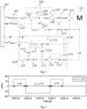
- Figure 2 shows an example of a pre-defined pulsating torque signal ⁇ ref according to embodiments.
- the illustrated pre-defined pulsating torque signal consists of a first positive (square) pulse having a first duration t step , a negative (square) pulse having a second duration 2 t step and a second positive (square) pulse having the first duration t step .
- the illustrated pre-defined pulsating torque signal corresponds specifically to a torque operating point (i.e., torque operating level) of 70 Nm.
- the value of t step 0.01 s is used in this example.
- the value of t step may be selected based on the bandwidth of the current controllers and minimum inertia of the rotor. Ideally, it is chosen to be small enough to keep the rotor movements small though large enough for the current controllers to attain steady state.
- Figure 3 shows an example of how the measurements are performed in order to estimate the error in the estimated angular position for a single torque operating point.
- the first (top) subfigure of Figure 3 illustrates the measurement of desired torque ⁇ ref
- the second subfigure of Figure 3 illustrates the measurement of the estimated angular position ⁇ est
- the third subfigure of Figure 3 illustrates the measurement of the actual angular position ⁇ r
- the fourth (bottom) subfigure of Figure 3 illustrates the measurement of the estimated angular speed ⁇ r before and after low-pass filtering (LPF).
- LPF low-pass filtering
- This convention applies for many types of synchronous motors, e.g., SynRM and PMaSynRM.
- IPM motors rely more on permanent magnet (PM) torque than reluctance torque and the typical convention there is to align the d -axis along the PM flux path. This is usually the negative saliency path.
- the system of Figure 1 cannot be used as such (without modifications) with IPM motors.
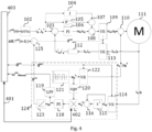
- Figure 4 illustrates an alternative, more generic system according to embodiments for overcoming the aforementioned incompatibility with the IPM motors.
- the system of Figure 4 corresponds to the system of Figure 1 apart from one minor (but important) change illustrated with elements 401, 402, 403.
- the system of Figure 1 is adapted in Figure 4 by enabling the system (or specifically the ⁇ ⁇ estimator state machine 403) to switch the sign of the result of the multiplication in the multiplication element 402 by including a correction term y in the multiplication.
- the correction term y may have a value of +1 or -1 depending on the type of the synchronous motor.
- the information on which sign to use at a given time may be maintained in the database of the ⁇ ⁇ estimator state machine 403.
- the ⁇ ⁇ estimator state machine 403 may control the switching of the sign in the multiplication element 402.
- the synchronic machines of the first type comprise at least Syn-RMs and PMaSynRMs while the synchronic machines of the second type comprise at least IPM motors.
- the system of Figure 4 may correspond to the system of Figure 1 and thus the operation of the system of Figure 4 is not discussed here in full for brevity.
- the rotor of the synchronous motor should preferably move as little as possible during the angular position error estimation procedure.
- the initial angular position of the rotor before applying a pre-defined pulsating torque signal should be as close as possible to the final angular position of the rotor after the applying the pre-defined pulsating torque signal.
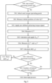
- Figure 5 illustrates a process according to embodiments for performing measurements for one or more torque operating points (preferably, a plurality of torque operating points) so as to also overcome the problem outlined in the previous paragraph.
- the process may be carried out by the system of Figure 1 or 4 .
- the process may be carried out by the ⁇ ⁇ estimator state machine 101 of Figure 1 or the ⁇ ⁇ estimator state machine 403 of Figure 4 .
- the process may be carried out by a drive.
- the entity carrying out the process is called simply an apparatus.
- the apparatus initially checks, in block 500, whether any torque operating points of the one or more torque operating points for which angular position error estimation has not been carried out still remain. If at least one torque operating point remains to be analyzed, the apparatus selects, in block 501, the next torque operation point ⁇ ref (in order) for which angular position error estimation is to be performed. Initially when no measurements have yet been performed, the action in block 501 may correspond simply to selection of first of the one or more torque operation points. This first of the one or more torque operation points may be the lowest torque operating point.
- the one or more torque operating points comprises a plurality of torque operating points
- the plurality of pre-defined pulsating torque signals corresponding to the plurality of torque operating points may be applied sequentially in order of increasing torque operating point (i.e., increasing torque level). In other embodiments, other order may be employed, as discussed above.
- the apparatus measures, in block 502, a zeroth value of an estimated angular position of the rotor of the synchronous motor ⁇ 0 est (at a zeroth time instance).
- This measurement is specifically performed before any torque signal is applied to the synchronous motor.
- the measurement may be performed based on the high-frequency voltage injected to the stator of the synchronous motor, as described above. Also as described above, a corresponding zeroth value of desired torque and/or an estimated angular speed of the rotor may also be measured in some embodiments.
- the apparatus After measuring the zeroth value(s), the apparatus applies, in block 503, the pre-defined pulsating torque corresponding to the selected torque operating point to the synchronous motor. This may be carried out as described in relation to Figure 1 .
- the apparatus compares, in block 508, an absolute difference between the zeroth value of the estimated angular position and an error-corrected first value of the estimated angular position against a first pre-defined threshold (i.e., a tolerance threshold).
- ⁇ r 1 est ⁇ 2 est ⁇ ⁇ r 2 est > ⁇ threshold
- ⁇ threshold is the first pre-defined threshold.
- the apparatus may, first, check whether the number of failures of the absolute difference between the zeroth value of the estimated angular position and the first value of the estimated angular position to exceed the first pre-defined threshold exceeds a second pre-defined threshold in block 509. If this is not the case, the apparatus repeats the angular position error estimation without changing the torque operating point (i.e., repeats at least blocks 502 to 508). If the number of failures exceeds the second pre-defined threshold, the apparatus may interrupt or stop, in block 510, the angular position error estimation process. The apparatus may also interrupt the angular position error estimation process also if no torque operating points are no longer left for angular position error estimation (i.e., if all the one or more torque operating points have been covered) in block 500.
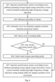
- the apparatus performs, sequentially for each of one or more torque operating points of a synchronous motor, angular position error estimation of the synchronous motor in the following manner (blocks 601 to 606).
- the one or more torque operating points and the associated one or more pre-defined pulsating torque signals and the order in which they are applied in the angular position error estimation may be defined as described in relation to Figure 5 .
- the apparatus estimates, in block 603, an error in the first value of the estimated angular position of the rotor based on the plurality of values and stores at least the error in the estimated angular position to a lookup table in a database.
- the estimating in block 603 may correspond to block 507 of Figure 5 .
- the apparatus selects, in block 606, the next torque operating point for angular position error estimation (if any exist in block 605).
- the angular position error estimation loop (blocks 601 to 606) is repeated for each of the one or more torque operating points.
- the apparatus 701 may further comprise different interfaces 710 such as an interface to a stator of a synchronous motor and optionally one or more signaling interfaces (TX/RX) comprising hardware and/or software for realizing communication connectivity according to one or more communication protocols.
- the one or more signaling interfaces 710 may comprise standard well-known components such as an amplifier, filter, frequency-converter, (de)modulator, and encoder/decoder circuitries, controlled by the corresponding controlling units, and one or more antennas.
- circuitry' also covers an implementation of merely a hardware circuit or processor (or multiple processors) or a portion of a hardware circuit or processor and its (or their) accompanying software and/or firmware.
- the term 'circuitry' also covers, for example and if applicable to the particular claim element, a baseband integrated circuit for an access node or a terminal device or other computing or network device.
- At least some of the processes described in connection with Figures 1 to 6 may be carried out by an apparatus comprising corresponding means for carrying out at least some of the described processes.
- Some example means for carrying out the processes may include at least one of the following: detector, processor (including dual-core and multiple-core processors), digital signal processor, controller, receiver, transmitter, encoder, decoder, memory, RAM, ROM, software, firmware, display, user interface, display circuitry, user interface circuitry, user interface software, display software, circuit, antenna, antenna circuitry, and circuitry.
- the at least one processor, the memory, and the computer program code form processing means or comprises one or more computer program code portions for carrying out one or more operations according to any one of the embodiments of Figures 1 to 6 or operations thereof.
- the computer program medium may be, for example but not limited to, a record medium, computer memory, read-only memory, electrical carrier signal, telecommunications signal, and software distribution package, for example.
- the computer program medium may be a non-transitory medium. Coding of software for carrying out the embodiments as shown and described is well within the scope of a person of ordinary skill in the art.
Landscapes
- Engineering & Computer Science (AREA)
- Power Engineering (AREA)
- Databases & Information Systems (AREA)
- Control Of Ac Motors In General (AREA)
Claims (15)
- Vorrichtung, aufweisend:Mittel zum Durchführen einer Winkelpositionsfehlerschätzung, sequenziell für jeden von einem oder mehreren Drehmomentbetriebspunkten eines Synchronmotors, durchBetreiben (601) des Synchronmotors (111) gemäß einem vordefinierten pulsierenden Drehmomentsignal unter Verwendung eines sensorlosen Vektorsteuerungsverfahrens mit Hochfrequenzspannungseinspeisung, wobei eine Spitzenamplitude des vordefinierten pulsierenden Drehmomentsignals einem Drehmomentbetriebspunkt des Synchronmotors entspricht und das vordefinierte pulsierende Drehmomentsignal einen Mittelwert Null aufweist,Messen (602), basierend auf einer Hochfrequenzkomponente eines von dem Synchronmotor (111) empfangenen Statorstromausgangssignals, zumindesteinen ersten Wert einer geschätzten Winkelposition eines Rotors des Synchronmotors,
 einen zweiten Wert der geschätzten Winkelposition,
 einen zweiten Wert einer geschätzten Winkelgeschwindigkeit,
 Schätzen (603) eines Fehlers, Δθ, im ersten Wert der geschätzten Winkelposition als
 Mittel zum Betreiben (607) des Synchronmotors (111) an dem einen oder mehreren Drehmomentbetriebspunkten im Anschluss an die Winkelpositionsfehlerschätzung unter Verwendung des sensorlosen Vektorsteuerungsverfahrens mit Hochfrequenzspannungseinspeisung, wobei jeder Fehler in der Winkelposition des Synchronmotors (111) beim Betrieb (607) an dem einen oder mehreren Drehmomentbetriebspunkten gemäß der Nachschlagetabelle korrigiert wird.
 - Vorrichtung nach Anspruch 1, wobei der eine oder mehrere Drehmomentbetriebspunkte eine Mehrzahl von Drehmomentbetriebspunkten aufweisen.
- Vorrichtung nach einem der vorhergehenden Ansprüche, wobei jeder Fehler in der Winkelposition des Synchronmotors (111) im Betrieb (607) an dem einen oder mehreren Drehmomentbetriebspunkten nach der Winkelpositionsfehlerschätzung gemäß der Nachschlagetabelle korrigiert wird durch:Berechnen einer korrigierten geschätzten Winkelposition für den Drehmomentbetriebspunkt τ(n) gemäß
 wobei θest ein Wert einer aktuellen geschätzten Winkelposition ist, wie sie durch das Vektorsteuerungsverfahren ausgewertet wird, τ ein dem Drehmomentbetriebspunkt zugeordneter Drehmomentwert ist,Δθ(τ(n)) ein Wert des Fehlers in der geschätzten Winkelposition ist, der in der Nachschlagetabelle aufrechterhalten wird, n den n-ten Drehmomentbetriebspunkt des einen oder mehrerer Drehmomentbetriebspunkte bezeichnet und x definiert ist als
 Verwenden der korrigierten geschätzten Winkelposition im sensorlosen Vektorsteuerungsverfahren.
 - Vorrichtung nach Anspruch 2, wobei jeder Fehler in der Winkelposition des Synchronmotors (111) im Betrieb (601) entsprechend dem vordefinierten pulsierenden Drehmomentsignal korrigiert wird, durch:Berechnen (505) einer korrigierten geschätzten Winkelposition für den Drehmomentbetriebspunkt τ(n) gemäß
 wobei θest ein Wert einer aktuellen geschätzten Winkelposition ist, wie sie durch das Vektorsteuerungsverfahren ausgewertet wird, τ ein dem Drehmomentbetriebspunkt zugeordneter Drehmomentwert ist,Δθ(τclosest ) ein Wert des Fehlers in der geschätzten Winkelposition ist, der für einen früheren Drehmomentbetriebspunkt berechnet wurde, der dem Drehmomentbetriebspunkt am nächsten liegt und der in der Nachschlagetabelle aufrechterhalten wird, n den n-ten Drehmomentbetriebspunkt des einen oder mehrerer Drehmomentbetriebspunkte bezeichnet und x definiert ist als
 Verwenden (505) der korrigierten geschätzten Winkelposition im sensorlosen Vektorsteuerungsverfahren.
 - Vorrichtung nach einem der Ansprüche 1 bis 3, wobei der eine oder mehrere Drehmomentbetriebspunkte zumindest drei Drehmomentbetriebspunkte aufweisen und jeder Fehler in der Winkelposition des Synchronmotors (111) im Betrieb gemäß dem vordefinierten pulsierenden Drehmomentsignal korrigiert wird durch:Berechnen einer korrigierten geschätzten Winkelposition für den Drehmomentbetriebspunkt τ(n) gemäß
 wobei θest ein Wert einer aktuellen geschätzten Winkelposition ist, wie sie durch das Vektorsteuerungsverfahren ausgewertet wird, τ ein einem Drehmomentbetriebspunkt zugeordneter Drehmomentwert ist, Δθ(τ(n)) ein Wert des Fehlers in der geschätzten Winkelposition für den Drehmomentbetriebspunkt τ(n) ist, n den n-ten Drehmomentbetriebspunkt der zumindest drei Drehmomentbetriebspunkte bezeichnet und x definiert ist als
 wobei der Begriff Δθ(τ(n)) durch lineare Extrapolation oder Interpolation von Werten des Fehlers in der geschätzten Winkelposition berechnet wird, die für frühere Drehmomentbetriebspunkte berechnet und in der Nachschlagetabelle aufrechterhalten werden; undVerwenden der korrigierten geschätzten Winkelposition im sensorlosen Vektorsteuerungsverfahren.
 - Vorrichtung nach einem der vorhergehenden Ansprüche, wobei die Mittel zum Durchführen der Winkelpositionsfehlerschätzung dazu ausgestaltet sind, den Betrieb (601) des Synchronmotors (111) gemäß dem vordefinierten pulsierenden Drehmomentsignal für jeden von einem oder mehreren Drehmomentbetriebspunkten des Synchronmotors (111) durchzuführen, durch:Erzeugen von Statorstromsignalen der d- und q-Achse basierend auf dem vordefinierten pulsierenden Drehmomentimpulssignal;Berechnen (103) eines ersten Differenzsignals als Differenz zwischen einem erzeugten d-Achsen-Statorstromsignal und einem gemessenen d-Achsen-Statorstromsignal des Synchronmotors und eines zweiten Differenzsignals als Differenz zwischen einem erzeugten q-Achsen-Statorstromsignal und einem gemessenen q-Achsen-Statorstromausgangssignal des Synchronmotors (111);Berechnen eines d-Achsen-Statorspannungssignals basierend auf dem ersten Differenzsignal und eines q-Achsen-Statorspannungssignals basierend auf dem zweiten Differenzsignal unter Verwendung eines ersten Proportional-Integral-Reglers (106), PI-Reglers;Umwandeln (109) der d- und q-Achsen-Statorspannungssignale in α- und β-Achsen-Statorspannungssignale unter Verwendung der inversen Park-Transformation; undAnlegen der α- und β-Achsen -Statorspannungssignale an einen Stator des Synchronmotors (111).
- Vorrichtung nach Anspruch 6, wobei die Mittel zum Durchführen der Winkelpositionsfehlerschätzung dazu ausgestaltet sind, das gemessene q-Achsen-Statorstromausgangssignal zu erfassen, durch:Empfangen von α- und β-Achsen-Statorstromausgangssignalen vom Synchronmotor (111);Erzeugen (113) von d-Achsen- und q-Achsen-Statorstromausgangssignalen basierend auf den α- und β-Achsen-Statorstromausgangssignalen unter Verwendung einer Park-Transformation basierend auf einem zuvor geschätzten Wert der geschätzten Winkelposition des Rotors; undBerechnen (112) eines Zeitmittelwerts über jedes der d- und q-Achsen-Statorstromausgangssignale.
- Vorrichtung nach Anspruch 6 oder 7, wobei die Mittel zum Durchführen der Winkelpositionsfehlerschätzung dazu ausgestaltet sind, die Hochfrequenzspannungseinspeisung durchzuführen durch:Erzeugen (121) eines hochfrequenten Rechteckachsen- oder q-Achsen-Statorspannungssignals mit einer Frequenz, die größer ist als eine Frequenz des vordefinierten pulsierenden Drehmomentsignals;Umwandeln (122) des hochfrequenten Rechteckachsen- oder q-Achsen-Statorspannungssignals in hochfrequente α- und β-Achsen-Statorspannungssignale unter Verwendung der inversen Park-Transformation basierend auf einem zuvor geschätzten Wert der geschätzten Winkelposition des Rotors; undEinspeisen (110) der hochfrequenten α- und β-Achsen-Statorspannungssignale in die α- und β-Achsen-Statorspannungssignale, die dem Synchronmotor (111) zugeführt werden sollen.
- Vorrichtung nach einem der vorhergehenden Ansprüche, wobei die Mittel zum Durchführen der Winkelpositionsfehlerschätzung dazu ausgestaltet sind, den Betrieb (601) des Synchronmotors (111) gemäß dem vordefinierten pulsierenden Drehmomentsignal durch weiteres Durchführen für jeden von einem oder mehreren Drehmomentbetriebspunkten des Synchronmotors (111) durchzuführen:Empfangen von α- und β-Achsen-Statorstromausgangssignalen vom Synchronmotor (111);Erzeugen (114) eines q-Achsen-Statorstromausgangssignals basierend auf den α- und β-Achsen-Statorstromausgangssignalen unter Verwendung einer Park-Transformation basierend auf einem zuvor geschätzten Wert der geschätzten Winkelposition des Rotors;Hochpassfiltern (115, 116) des q-Achsen-Statorstromausgangssignals, um eine hochfrequente q-Achsen-Statorstromausgangskomponente zu isolieren, die aus der Hochfrequenzspannungseinspeisung resultiert;Berechnen eines Produkts (117) aus der hochfrequenten q-Achsen-Statorstromausgangskomponente und einem Signal, das durch Anwenden einer Vorzeichenfunktion (120) auf das hochfrequente Rechteck-Achsen-Statorspannungssignal gebildet wird;Berechnen, unter Verwendung einer zweiten PI-Steuerung (118), eines ersten Signals, das der geschätzten Winkelgeschwindigkeit basierend auf dem Produkt entspricht;Integrieren (123) des ersten Signals, das der geschätzten Winkelgeschwindigkeit entspricht, über die Zeit, um ein Signal zu bilden, das der geschätzten Winkelposition entspricht; undTiefpassfiltern (119) des ersten Signals, das der geschätzten Winkelgeschwindigkeit entspricht, um ein zweites Signal zu bilden, das der geschätzten Winkelgeschwindigkeit entspricht.
- Vorrichtung nach einem der Ansprüche 1 bis 8, wobei die Mittel zum Durchführen der Winkelpositionsfehlerschätzung dazu ausgestaltet sind, den Betrieb (601) des Synchronmotors (111) gemäß dem vordefinierten pulsierenden Drehmomentsignal unter Verwendung des sensorlosen Vektorsteuerungsverfahrens durchzuführen, das die Hochfrequenzspannungseinspeisung durch weiteres Durchführen für jeden von einem oder mehreren Drehmomentbetriebspunkten des Synchronmotors (111) verwendet:Empfangen von α- und β-Achsen-Statorstromausgangssignalen vom Synchronmotor (111);Erzeugen (114) eines q-Achsen-Statorstromausgangssignals basierend auf den α- und β-Achsen-Statorstromausgangssignalen unter Verwendung einer Park-Transformation basierend auf einem zuvor geschätzten Wert der geschätzten Winkelposition des Rotors;Hochpassfiltern (115, 116) des q-Achsen-Statorstromausgangssignals, um eine hochfrequente q-Achsen-Statorstromausgangskomponente zu isolieren, wobei die hochfrequente q-Achsen-Statorstromausgangskomponente einer Reaktion auf das dem Synchronmotor (111) zugeführte hochfrequente Rechteck-Achsen-Statorstromsignal entspricht;Berechnen eines Produkts (402) aus der hochfrequenten q-Achsen-Statorstromausgangskomponente, einem Signal, das durch Anwenden einer Vorzeichenfunktion (120) auf das hochfrequente Rechteck- Achsen-Statorspannungssignal gebildet wird, und einem Korrekturterm, der in der Datenbank aufrechterhalten wird, wobei der Korrekturterm je nach Typ des Synchronmotors (111) den Wert +1 oder -1 hat;Berechnen, unter Verwendung einer zweiten PI-Steuerung (118), eines ersten Signals, das der geschätzten Winkelgeschwindigkeit basierend auf dem Produkt entspricht;Integrieren (123) des ersten Signals, das der geschätzten Winkelgeschwindigkeit entspricht, über die Zeit, um ein Signal zu bilden, das der geschätzten Winkelposition entspricht; undTiefpassfiltern (119) des ersten Signals, das der geschätzten Winkelgeschwindigkeit entspricht, um ein zweites Signal zu bilden, das der geschätzten Winkelgeschwindigkeit entspricht.
- Vorrichtung nach einem der vorhergehenden Ansprüche, wobei die Mittel zum Durchführen der Winkelpositionsfehlerschätzung dazu ausgestaltet sind, für jeden der ein oder mehreren Drehmomentbetriebspunkte ferner durchzuführen:Messen (502) eines nullten Wertes der geschätzten Winkelposition vor dem Betreiben (503, 601) des Synchronmotors (111) gemäß dem vordefinierten pulsierenden Drehmomentsignal;Vergleichen (507) einer absoluten Differenz zwischen dem nullten Wert der geschätzten Winkelposition und einem fehlerkorrigierten ersten Wert der geschätzten Winkelposition mit einem ersten vordefinierten Schwellenwert, wobei der fehlerkorrigierte erste Wert der geschätzten Winkelposition als
 als Reaktion darauf, dass die absolute Differenz den ersten vorab definierten Schwellenwert nicht überschreitet, Durchführen des Speicherns (511) und, wenn für zumindest einen Drehmomentbetriebspunkt des einen oder mehrerer Drehmomentbetriebspunkte Daten noch nicht in der Nachschlagetabelle gespeichert sind, Fortfahren, eine Winkelpositionsfehlerschätzung für einen nächsten Drehmomentbetriebspunkt des einen oder mehrerer Drehmomentbetriebspunkte, für den die Daten noch nicht in der Nachschlagetabelle gespeichert sind, durchzuführen; undals Reaktion darauf, dass die absolute Differenz den ersten vordefinierten Schwellenwert überschreitet, Wiederholen der Winkelpositionsfehlerschätzung, ohne den Drehmomentbetriebspunkt zu verändern.
 - Vorrichtung nach Anspruch 11, wobei die Mittel zum Durchführen der Winkelpositionsfehlerschätzung ferner dazu ausgestaltet sind, für jeden der ein oder mehreren Drehmomentbetriebspunkte Folgendes durchzuführen:
als Reaktion darauf, dass die Anzahl der Fehler der absoluten Differenz zwischen dem nullten Wert der geschätzten Winkelposition und dem ersten Wert der geschätzten Winkelposition, die den ersten vordefinierten Schwellenwert überschreitet, einen zweiten vordefinierten Schwellenwert (509) überschreitet, Anhalten (510) der Winkelpositionsfehlerschätzung. - Vorrichtung nach einem der vorhergehenden Ansprüche, wobei das vordefinierte pulsierende Drehmomentsignal einen oder mehrere positive Rechteckimpulse und einen oder mehrere negative Rechteckimpulse aufweist, die in einer solchen Reihenfolge angeordnet sind, dass die Gesamtbewegung des Rotors während einer Anwendung des vordefinierten pulsierenden Drehmomentsignals minimiert wird.
- Antrieb zum Antreiben eines Synchronmotors (111), wobei der Antrieb die Vorrichtung nach einem der vorhergehenden Ansprüche aufweist.
- Verfahren, aufweisend:
Durchführen, sequenziell für jeden von einem oder mehreren Drehmomentbetriebspunkten eines Synchronmotors (111), einer Winkelpositionsfehlerschätzung durch:Betreiben (601) des Synchronmotors (111) gemäß einem vordefinierten pulsierenden Drehmomentsignal unter Verwendung eines sensorlosen Vektorsteuerungsverfahrens mit Hochfrequenzspannungseinspeisung, wobei eine Spitzenamplitude des vordefinierten pulsierenden Drehmomentsignals einem Drehmomentbetriebspunkt des Synchronmotors (111) entspricht und das vordefinierte pulsierende Drehmomentsignal einen Mittelwert Null aufweist;Messen (602), basierend auf einer Hochfrequenzkomponente eines von dem Synchronmotor (111) empfangenen Statorstromausgangssignals, zumindesteinen ersten Wert einer geschätzten Winkelposition eines Rotors des Synchronmotors (111), einen zweiten Wert der geschätzten Winkelposition,
 einen zweiten Wert einer geschätzten Winkelgeschwindigkeit,
 Schätzen (603) eines Fehlers, Δθ, im ersten Wert der geschätzten Winkelposition als
 Speichern (604) zumindest des Fehlers in der geschätzten Winkelposition in einer Nachschlagetabelle in einer Datenbank,wobei das Verfahren ferner im Anschluss an die Winkelpositionsfehlerschätzung Folgendes aufweist:
Betreiben (607) des Synchronmotors (111) an dem einen oder mehreren Drehmomentbetriebspunkten unter Verwendung des sensorlosen Vektorsteuerungsverfahrens mit Hochfrequenzspannungseinspeisung, wobei jeder Fehler in der Winkelposition des Synchronmotors (111) beim Betrieb an dem einen oder mehreren Drehmomentbetriebspunkten gemäß der Nachschlagetabelle korrigiert wird.
Priority Applications (3)
| Application Number | Priority Date | Filing Date | Title |
|---|---|---|---|
| EP20170391.5A EP3902135B1 (de) | 2020-04-20 | 2020-04-20 | Winkelpositionsfehlerschätzung im stillstand für hochfrequenzspannungsinjektion |
| US17/231,708 US11342871B2 (en) | 2020-04-20 | 2021-04-15 | Angular position error estimation at standstill for high-frequency voltage injection |
| CN202110419396.3A CN113541550B (zh) | 2020-04-20 | 2021-04-19 | 针对高频电压注入的静止下的角度位置误差估计 |
Applications Claiming Priority (1)
| Application Number | Priority Date | Filing Date | Title |
|---|---|---|---|
| EP20170391.5A EP3902135B1 (de) | 2020-04-20 | 2020-04-20 | Winkelpositionsfehlerschätzung im stillstand für hochfrequenzspannungsinjektion |
Publications (3)
| Publication Number | Publication Date |
|---|---|
| EP3902135A1 EP3902135A1 (de) | 2021-10-27 |
| EP3902135B1 true EP3902135B1 (de) | 2023-12-13 |
| EP3902135C0 EP3902135C0 (de) | 2023-12-13 |
Family
ID=70333892
Family Applications (1)
| Application Number | Title | Priority Date | Filing Date |
|---|---|---|---|
| EP20170391.5A Active EP3902135B1 (de) | 2020-04-20 | 2020-04-20 | Winkelpositionsfehlerschätzung im stillstand für hochfrequenzspannungsinjektion |
Country Status (3)
| Country | Link |
|---|---|
| US (1) | US11342871B2 (de) |
| EP (1) | EP3902135B1 (de) |
| CN (1) | CN113541550B (de) |
Families Citing this family (4)
| Publication number | Priority date | Publication date | Assignee | Title |
|---|---|---|---|---|
| US12227168B2 (en) * | 2021-03-31 | 2025-02-18 | Sensata Technologies, Inc. | Accurate error estimation in E-motor sensors |
| CN114785208B (zh) * | 2022-05-18 | 2022-10-25 | 哈尔滨工业大学 | 永磁同步电机无位置传感器控制转子位置误差观测方法 |
| CN115542807B (zh) * | 2022-09-29 | 2025-09-05 | 深圳市英威腾电气股份有限公司 | 一种基于fpga确定电角度的方法、装置及介质 |
| EP4498098A1 (de) * | 2023-07-27 | 2025-01-29 | Valeo eAutomotive Germany GmbH | Wechselstromerfassungsverfahren |
Family Cites Families (10)
| Publication number | Priority date | Publication date | Assignee | Title |
|---|---|---|---|---|
| US6137258A (en) * | 1998-10-26 | 2000-10-24 | General Electric Company | System for speed-sensorless control of an induction machine |
| JP4178834B2 (ja) * | 2002-05-24 | 2008-11-12 | 株式会社明電舎 | Pmモータの制御装置 |
| DE602004020349D1 (de) * | 2004-10-28 | 2009-05-14 | Abb Oy | Verfahren zum Schätzen der Rotorgeschwindigkeit und Position einer Permanentmagnetsynchronmaschine |
| DE112006002501T5 (de) * | 2005-09-26 | 2008-08-07 | Kabushiki Kaisha Yaskawa Denki, Kitakyushu | Ermittlungsvorrichtung und -verfahren für Anfangspolposition für einen synchronen Wechselstrommotor |
| US8253360B2 (en) * | 2009-07-15 | 2012-08-28 | GM Global Technology Operations LLC | Vector controlled motor drive system implementing pulse width modulated (PWM) waveforms |
| EP2552014A3 (de) * | 2011-07-28 | 2016-08-17 | Vestas Wind Systems A/S | Verfahren zur Positionierung einer sensorlosen Steuerung einer Elektromaschine |
| CN105409110A (zh) * | 2013-08-19 | 2016-03-16 | 株式会社安川电机 | 电机驱动系统以及电机控制装置 |
| US9948224B1 (en) * | 2016-10-17 | 2018-04-17 | General Electric Company | System and method for sensorless control of electric machines using magnetic alignment signatures |
| WO2018154733A1 (ja) * | 2017-02-24 | 2018-08-30 | 三菱電機株式会社 | 電動機のトルク脈動補正装置および補正方法、エレベーターの制御装置 |
| JP7699908B2 (ja) * | 2018-11-20 | 2025-06-30 | 株式会社日立産機システム | 電力変換装置 |
-
2020
- 2020-04-20 EP EP20170391.5A patent/EP3902135B1/de active Active
-
2021
- 2021-04-15 US US17/231,708 patent/US11342871B2/en active Active
- 2021-04-19 CN CN202110419396.3A patent/CN113541550B/zh active Active
Also Published As
| Publication number | Publication date |
|---|---|
| CN113541550B (zh) | 2025-02-25 |
| EP3902135C0 (de) | 2023-12-13 |
| CN113541550A (zh) | 2021-10-22 |
| EP3902135A1 (de) | 2021-10-27 |
| US11342871B2 (en) | 2022-05-24 |
| US20210328532A1 (en) | 2021-10-21 |
Similar Documents
| Publication | Publication Date | Title |
|---|---|---|
| US11342871B2 (en) | Angular position error estimation at standstill for high-frequency voltage injection | |
| EP1133050B1 (de) | Verfahren zur Schätzung der Rotorlage eines Synchronmotors, Verfahren zur Steuerung eines sensorlosen Synchronmotors und eine Steuerung für einen Synchronmotor | |
| CN107431453B (zh) | 无传感器换向方法 | |
| JP4059039B2 (ja) | 同期電動機の制御装置 | |
| EP1432112A1 (de) | Polpositionserfassungsverfahren für einen elektromotor, polpositionserfassungsvorrichtung und elektromotor-steuervorrichtung damit | |
| EP3054583B1 (de) | Verfahren und System zur Schätzung differenzieller Induktivitäten in einer elektrischen Maschine | |
| EP2552015B1 (de) | Verfahren zur Positionierung einer sensorlosen Steuerung einer Elektromaschine | |
| JP2005130582A (ja) | 磁極位置検出装置及び方法 | |
| KR102426117B1 (ko) | 전동기 제어 시스템 및 그에 대한 방법 | |
| CN102647132B (zh) | 估计同步磁阻电机启动时的转子角度和速度的方法及设备 | |
| US9553532B2 (en) | Control device for alternating current rotary machine | |
| JP2002281782A (ja) | モータ制御装置 | |
| KR102409792B1 (ko) | 영구 자석 동기 전동기의 제어 장치, 마이크로 컴퓨터, 전동기 시스템 및 영구 자석 동기 전동기의 운전 방법 | |
| Paulus et al. | Saliency based sensorless field-oriented control for permanent magnet synchronous machines in the whole speed range | |
| JP2006158046A (ja) | 交流電動機のセンサレス制御方法および装置 | |
| Kim et al. | High performance position sensorless control using rotating voltage signal injection in IPMSM | |
| JP5743344B2 (ja) | 同期電動機の制御装置 | |
| Liu et al. | A new sensorless control strategy by high-frequency pulsating signal injection into stationary reference frame | |
| Montanari et al. | Speed sensorless control of induction motor based on indirect field-orientation | |
| Bamba et al. | Estimation of rotor position for switched reluctance motor at standstill | |
| JP2002272195A (ja) | 同期電動機の制御装置 | |
| Lehmann et al. | Sensorless control techniques as redundancy for the control of permanent magnet synchronous machines in electric vehicles | |
| JP4596200B2 (ja) | 永久磁石形同期電動機の制御装置 | |
| JP7082369B2 (ja) | 電動機の駆動装置 | |
| JP4449419B2 (ja) | 同期電動機の制御装置 |
Legal Events
| Date | Code | Title | Description |
|---|---|---|---|
| PUAI | Public reference made under article 153(3) epc to a published international application that has entered the european phase |
Free format text: ORIGINAL CODE: 0009012 |
|
| STAA | Information on the status of an ep patent application or granted ep patent |
Free format text: STATUS: THE APPLICATION HAS BEEN PUBLISHED |
|
| AK | Designated contracting states |
Kind code of ref document: A1 Designated state(s): AL AT BE BG CH CY CZ DE DK EE ES FI FR GB GR HR HU IE IS IT LI LT LU LV MC MK MT NL NO PL PT RO RS SE SI SK SM TR |
|
| B565 | Issuance of search results under rule 164(2) epc |
Effective date: 20200911 |
|
| STAA | Information on the status of an ep patent application or granted ep patent |
Free format text: STATUS: REQUEST FOR EXAMINATION WAS MADE |
|
| 17P | Request for examination filed |
Effective date: 20220304 |
|
| RBV | Designated contracting states (corrected) |
Designated state(s): AL AT BE BG CH CY CZ DE DK EE ES FI FR GB GR HR HU IE IS IT LI LT LU LV MC MK MT NL NO PL PT RO RS SE SI SK SM TR |
|
| REG | Reference to a national code |
Ref country code: DE Free format text: PREVIOUS MAIN CLASS: H02P0006180000 Ipc: H02P0021180000 Ref country code: DE Ref legal event code: R079 Ref document number: 602020022557 Country of ref document: DE Free format text: PREVIOUS MAIN CLASS: H02P0006180000 Ipc: H02P0021180000 |
|
| GRAP | Despatch of communication of intention to grant a patent |
Free format text: ORIGINAL CODE: EPIDOSNIGR1 |
|
| STAA | Information on the status of an ep patent application or granted ep patent |
Free format text: STATUS: GRANT OF PATENT IS INTENDED |
|
| RIC1 | Information provided on ipc code assigned before grant |
Ipc: H02P 6/18 20160101ALI20230613BHEP Ipc: H02P 21/00 20160101ALI20230613BHEP Ipc: H02P 21/18 20160101AFI20230613BHEP |
|
| INTG | Intention to grant announced |
Effective date: 20230714 |
|
| GRAS | Grant fee paid |
Free format text: ORIGINAL CODE: EPIDOSNIGR3 |
|
| GRAA | (expected) grant |
Free format text: ORIGINAL CODE: 0009210 |
|
| STAA | Information on the status of an ep patent application or granted ep patent |
Free format text: STATUS: THE PATENT HAS BEEN GRANTED |
|
| AK | Designated contracting states |
Kind code of ref document: B1 Designated state(s): AL AT BE BG CH CY CZ DE DK EE ES FI FR GB GR HR HU IE IS IT LI LT LU LV MC MK MT NL NO PL PT RO RS SE SI SK SM TR |
|
| REG | Reference to a national code |
Ref country code: GB Ref legal event code: FG4D |
|
| REG | Reference to a national code |
Ref country code: CH Ref legal event code: EP |
|
| REG | Reference to a national code |
Ref country code: DE Ref legal event code: R096 Ref document number: 602020022557 Country of ref document: DE |
|
| REG | Reference to a national code |
Ref country code: IE Ref legal event code: FG4D |
|
| U01 | Request for unitary effect filed |
Effective date: 20240104 |
|
| U07 | Unitary effect registered |
Designated state(s): AT BE BG DE DK EE FI FR IT LT LU LV MT NL PT SE SI Effective date: 20240115 |
|
| PG25 | Lapsed in a contracting state [announced via postgrant information from national office to epo] |
Ref country code: GR Free format text: LAPSE BECAUSE OF FAILURE TO SUBMIT A TRANSLATION OF THE DESCRIPTION OR TO PAY THE FEE WITHIN THE PRESCRIBED TIME-LIMIT Effective date: 20240314 |
|
| PG25 | Lapsed in a contracting state [announced via postgrant information from national office to epo] |
Ref country code: ES Free format text: LAPSE BECAUSE OF FAILURE TO SUBMIT A TRANSLATION OF THE DESCRIPTION OR TO PAY THE FEE WITHIN THE PRESCRIBED TIME-LIMIT Effective date: 20231213 |
|
| PG25 | Lapsed in a contracting state [announced via postgrant information from national office to epo] |
Ref country code: GR Free format text: LAPSE BECAUSE OF FAILURE TO SUBMIT A TRANSLATION OF THE DESCRIPTION OR TO PAY THE FEE WITHIN THE PRESCRIBED TIME-LIMIT Effective date: 20240314 Ref country code: ES Free format text: LAPSE BECAUSE OF FAILURE TO SUBMIT A TRANSLATION OF THE DESCRIPTION OR TO PAY THE FEE WITHIN THE PRESCRIBED TIME-LIMIT Effective date: 20231213 |
|
| U20 | Renewal fee for the european patent with unitary effect paid |
Year of fee payment: 5 Effective date: 20240424 |
|
| PG25 | Lapsed in a contracting state [announced via postgrant information from national office to epo] |
Ref country code: RS Free format text: LAPSE BECAUSE OF FAILURE TO SUBMIT A TRANSLATION OF THE DESCRIPTION OR TO PAY THE FEE WITHIN THE PRESCRIBED TIME-LIMIT Effective date: 20231213 Ref country code: NO Free format text: LAPSE BECAUSE OF FAILURE TO SUBMIT A TRANSLATION OF THE DESCRIPTION OR TO PAY THE FEE WITHIN THE PRESCRIBED TIME-LIMIT Effective date: 20240313 Ref country code: HR Free format text: LAPSE BECAUSE OF FAILURE TO SUBMIT A TRANSLATION OF THE DESCRIPTION OR TO PAY THE FEE WITHIN THE PRESCRIBED TIME-LIMIT Effective date: 20231213 |
|
| PG25 | Lapsed in a contracting state [announced via postgrant information from national office to epo] |
Ref country code: IS Free format text: LAPSE BECAUSE OF FAILURE TO SUBMIT A TRANSLATION OF THE DESCRIPTION OR TO PAY THE FEE WITHIN THE PRESCRIBED TIME-LIMIT Effective date: 20240413 |
|
| PG25 | Lapsed in a contracting state [announced via postgrant information from national office to epo] |
Ref country code: CZ Free format text: LAPSE BECAUSE OF FAILURE TO SUBMIT A TRANSLATION OF THE DESCRIPTION OR TO PAY THE FEE WITHIN THE PRESCRIBED TIME-LIMIT Effective date: 20231213 |
|
| PG25 | Lapsed in a contracting state [announced via postgrant information from national office to epo] |
Ref country code: SK Free format text: LAPSE BECAUSE OF FAILURE TO SUBMIT A TRANSLATION OF THE DESCRIPTION OR TO PAY THE FEE WITHIN THE PRESCRIBED TIME-LIMIT Effective date: 20231213 |
|
| PG25 | Lapsed in a contracting state [announced via postgrant information from national office to epo] |
Ref country code: SM Free format text: LAPSE BECAUSE OF FAILURE TO SUBMIT A TRANSLATION OF THE DESCRIPTION OR TO PAY THE FEE WITHIN THE PRESCRIBED TIME-LIMIT Effective date: 20231213 Ref country code: SK Free format text: LAPSE BECAUSE OF FAILURE TO SUBMIT A TRANSLATION OF THE DESCRIPTION OR TO PAY THE FEE WITHIN THE PRESCRIBED TIME-LIMIT Effective date: 20231213 Ref country code: RO Free format text: LAPSE BECAUSE OF FAILURE TO SUBMIT A TRANSLATION OF THE DESCRIPTION OR TO PAY THE FEE WITHIN THE PRESCRIBED TIME-LIMIT Effective date: 20231213 Ref country code: IS Free format text: LAPSE BECAUSE OF FAILURE TO SUBMIT A TRANSLATION OF THE DESCRIPTION OR TO PAY THE FEE WITHIN THE PRESCRIBED TIME-LIMIT Effective date: 20240413 Ref country code: CZ Free format text: LAPSE BECAUSE OF FAILURE TO SUBMIT A TRANSLATION OF THE DESCRIPTION OR TO PAY THE FEE WITHIN THE PRESCRIBED TIME-LIMIT Effective date: 20231213 |
|
| PG25 | Lapsed in a contracting state [announced via postgrant information from national office to epo] |
Ref country code: PL Free format text: LAPSE BECAUSE OF FAILURE TO SUBMIT A TRANSLATION OF THE DESCRIPTION OR TO PAY THE FEE WITHIN THE PRESCRIBED TIME-LIMIT Effective date: 20231213 |
|
| PG25 | Lapsed in a contracting state [announced via postgrant information from national office to epo] |
Ref country code: PL Free format text: LAPSE BECAUSE OF FAILURE TO SUBMIT A TRANSLATION OF THE DESCRIPTION OR TO PAY THE FEE WITHIN THE PRESCRIBED TIME-LIMIT Effective date: 20231213 |
|
| REG | Reference to a national code |
Ref country code: DE Ref legal event code: R097 Ref document number: 602020022557 Country of ref document: DE |
|
| PLBE | No opposition filed within time limit |
Free format text: ORIGINAL CODE: 0009261 |
|
| STAA | Information on the status of an ep patent application or granted ep patent |
Free format text: STATUS: NO OPPOSITION FILED WITHIN TIME LIMIT |
|
| 26N | No opposition filed |
Effective date: 20240916 |
|
| PG25 | Lapsed in a contracting state [announced via postgrant information from national office to epo] |
Ref country code: MC Free format text: LAPSE BECAUSE OF FAILURE TO SUBMIT A TRANSLATION OF THE DESCRIPTION OR TO PAY THE FEE WITHIN THE PRESCRIBED TIME-LIMIT Effective date: 20231213 |
|
| PG25 | Lapsed in a contracting state [announced via postgrant information from national office to epo] |
Ref country code: MC Free format text: LAPSE BECAUSE OF FAILURE TO SUBMIT A TRANSLATION OF THE DESCRIPTION OR TO PAY THE FEE WITHIN THE PRESCRIBED TIME-LIMIT Effective date: 20231213 |
|
| REG | Reference to a national code |
Ref country code: CH Ref legal event code: PL |
|
| GBPC | Gb: european patent ceased through non-payment of renewal fee |
Effective date: 20240420 |
|
| PG25 | Lapsed in a contracting state [announced via postgrant information from national office to epo] |
Ref country code: GB Free format text: LAPSE BECAUSE OF NON-PAYMENT OF DUE FEES Effective date: 20240420 |
|
| PG25 | Lapsed in a contracting state [announced via postgrant information from national office to epo] |
Ref country code: GB Free format text: LAPSE BECAUSE OF NON-PAYMENT OF DUE FEES Effective date: 20240420 Ref country code: CH Free format text: LAPSE BECAUSE OF NON-PAYMENT OF DUE FEES Effective date: 20240430 |
|
| PG25 | Lapsed in a contracting state [announced via postgrant information from national office to epo] |
Ref country code: IE Free format text: LAPSE BECAUSE OF NON-PAYMENT OF DUE FEES Effective date: 20240420 |
|
| U20 | Renewal fee for the european patent with unitary effect paid |
Year of fee payment: 6 Effective date: 20250425 |
|
| PG25 | Lapsed in a contracting state [announced via postgrant information from national office to epo] |
Ref country code: CY Free format text: LAPSE BECAUSE OF FAILURE TO SUBMIT A TRANSLATION OF THE DESCRIPTION OR TO PAY THE FEE WITHIN THE PRESCRIBED TIME-LIMIT; INVALID AB INITIO Effective date: 20200420 |
|
| PG25 | Lapsed in a contracting state [announced via postgrant information from national office to epo] |
Ref country code: HU Free format text: LAPSE BECAUSE OF FAILURE TO SUBMIT A TRANSLATION OF THE DESCRIPTION OR TO PAY THE FEE WITHIN THE PRESCRIBED TIME-LIMIT; INVALID AB INITIO Effective date: 20200420 |