EP3903643A1 - Dispositif parasoleil - Google Patents
Dispositif parasoleil Download PDFInfo
- Publication number
- EP3903643A1 EP3903643A1 EP21170997.7A EP21170997A EP3903643A1 EP 3903643 A1 EP3903643 A1 EP 3903643A1 EP 21170997 A EP21170997 A EP 21170997A EP 3903643 A1 EP3903643 A1 EP 3903643A1
- Authority
- EP
- European Patent Office
- Prior art keywords
- sunshade
- elements
- sunbed
- canvas
- sunshade device
- Prior art date
- Legal status (The legal status is an assumption and is not a legal conclusion. Google has not performed a legal analysis and makes no representation as to the accuracy of the status listed.)
- Pending
Links
Images






Classifications
-
- A—HUMAN NECESSITIES
- A47—FURNITURE; DOMESTIC ARTICLES OR APPLIANCES; COFFEE MILLS; SPICE MILLS; SUCTION CLEANERS IN GENERAL
- A47C—CHAIRS; SOFAS; BEDS
- A47C7/00—Parts, details, or accessories of chairs or stools
- A47C7/62—Accessories for chairs
- A47C7/66—Means to protect against weather
-
- A—HUMAN NECESSITIES
- A47—FURNITURE; DOMESTIC ARTICLES OR APPLIANCES; COFFEE MILLS; SPICE MILLS; SUCTION CLEANERS IN GENERAL
- A47C—CHAIRS; SOFAS; BEDS
- A47C1/00—Chairs adapted for special purposes
- A47C1/14—Beach chairs ; Chairs for outdoor use, e.g. chairs for relaxation or sun-tanning
- A47C1/143—Chaise lounges
Definitions
- sunshade devices which have the purpose of projecting an area of shade on users resting or lying underneath them.
- the sunshade canvas When it is desired to project an area of shade, the sunshade canvas is unwound from the spring-loaded retractile roller and is anchored, at the end opposite to the one wound on the roller, to a transverse element supported by an end portion of the second pair of extensible telescopic rods.
- An aim of the invention is to provide a sunshade device of the type referred to at the start of the present description, that is practical and simple to use for a user, and that presents a greater versatility of use.
- a further aim of the invention is to provide a sunshade device of the type referred to at the start of the present description that is versatile, i.e. adaptable, if so required, to structures different from one another, such as a deck-chair, a sunbed, or a recliner, or the like.
- a further aim of the invention is to provide a sunshade device of the type referred to at the start of the present description that is inexpensive and simple to implement.
- the subject of the present invention is a sunshade device prearranged for being mounted on a sunbed or the like, comprising:
- the sunshade device is characterized in that the two longitudinal elements are of a telescopic or extensible/retractable type, and the sunshade structure, in particular in a generally rear end portion thereof, has associated thereto, or is configured to provide, an arrangement for unrolling or stretching out and for rolling up or compacting the canvas or the like, in such a way that the sunshade structure can be extended or retracted in the direction of the length of the sunbed or the like.
- the user is able to adjust the extent of the area of shade projected by the sunshade device by acting on the level of extension/retraction of the longitudinal elements and varying accordingly the level of unrolling/rolling-up of the canvas supported between them.
- the solution also enables containment of the overall dimensions of the device, when it is not in use.
- the two upright elements are of a telescopic or extensible/retractable type, in such a way that the sunshade structure can, when so required, be raised or lowered with respect to the structure of the sunbed or the like, thereby facilitating adjustment in height of the position of use of the device.
- the two longitudinal elements each comprise a plurality of slidably coupled elements and one or more elements for supporting the canvas or the like, the supporting element or each supporting element extending between two homologous slidable elements of the two longitudinal elements.
- the supporting elements enable optimal positioning and good stability of the canvas to be achieved, even when the latter is unwound or stretched out to a significant extent, for example for a length equal to that of the sunbed.
- the supporting element or each supporting element has an end portion associated to a corresponding end portion of the respective slidable element. Thanks to this characteristic, the slidable elements of the longitudinal elements can be housed in a telescopic way inside one another, to a prevalent extent, thereby reducing the overall dimensions of the device when it is not in use.
- the upright elements are connected in an articulated way to the sunshade structure by means of at least two respective upper articulation systems.
- the upright elements are connected in an articulated way to the structure of the sunbed or the like by means of at least two respective bottom lower articulation systems. Thanks to one or both of these characteristics, the user has the possibility of adjusting the inclination of the sunshade structure with respect to the sunbed or the like; the characteristics in question are moreover advantageous in order to enable folding of the upright on the sunshade structure in order to reduce the overall dimensions of the sunshade device when it is not in use.
- the upright elements each comprise a plurality of slidably coupled elements and a corresponding adjustment system, prearranged for enabling and clamping raising or lowering of the sunshade structure with respect to the structure of the sunbed or the like.
- Another subject of the present invention is a sunbed, mounted on which is the sunshade device in any one of the embodiments described above.
- references to "an embodiment”, “one embodiment”, or “various embodiments” and the like, in the framework of the present description is intended to point out that at least one particular configuration, structure, or characteristic described in relation to an embodiment is comprised in at least one embodiment.
- phrases such as “in an embodiment”, “in one embodiment”, “in various embodiments”, and the like that may be present in various points of this description do not necessarily refer to one and the same embodiment, but may instead refer to different embodiments.
- particular conformations, structures, or characteristics defined in the framework of the present description may be combined in any adequate way in one or more embodiments, even different from the ones represented.
- a sunshade device prearranged for being associated to, or mounted on, a sunbed or the like, where the term "the like" in the way in which it is used herein regards any other known structure suitable for being used in seaside-resort establishments, on terraces, in meadows or generic open places, and on which it is possible to sit, rest, or lie down.
- the sunshade device 1 is mounted on a sunbed, designated by the number 2.
- Other examples, which are not to be understood in a limiting sense, of structures on which the sunbathing device 1 can be mounted are a deck-chair or a recliner.
- the sunbed 2 comprises two rigid resting elements 3 and 3', which are prearranged for resting the sunbed 2 on the underlying ground and may be of any type known in the art.
- the sunbed 2 comprises more than two resting elements 3, 3'.
- the resting elements 3, 3' support a frame comprising a first structure, designated by the reference 4, and a second structure, designated by the reference 5.
- the resting elements 3, 3' are preferably connected in an articulated way to the first structure 4 and can therefore be displaced adjacent thereto when it is desired to reduce the volume occupied by the sunbed 2, for example when it is desired to displace or store away the sunbed 2.
- the second structure 5 is connected in an articulated way to an end portion of the first structure 4, in such a way that the angle ⁇ comprised between the first structure 4 and the second structure 5 can be changed as desired by the user.
- the angle ⁇ can have a minimum value of amplitude close or equal to approximately 0° in the condition where the second structure 5 is folded on the first structure 4 (not illustrated), and a maximum value of amplitude close or equal to approximately 180° in the condition where the second structure 5 and the first structure 4 are substantially coplanar, as illustrated, for example, in Figure 23 .
- the frame comprising the first structure 4 and the second structure 5 supports a resting surface 6, on which the user rests, sits, or lies during use of the sunbed 2.
- the resting surface 6 is a canvas stretched out between the elements of the aforesaid frame. It is to be understood that the constructional details of the resting elements 3, 3' and of the frame may be of any type known in the art and may be made of any material known for being used for the purpose, for example wood, steel, plastic, aluminium.
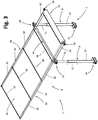
- the sunshade device 1 comprises a supporting structure, designated as a whole by the number 7, and a sunshade structure, designated as a whole by the number 8, associated at the top to the supporting structure 7.
- the supporting structure 7 is prearranged for anchorage of the sunshade device 1 on the sunbed 2.
- the sunshade device 1 is anchored on the sunbed 2 in a position corresponding to a portion of the second structure 5, but it is also possible for the sunshade device 1 to be anchored on the sunbed 2 in a position corresponding to a portion of the first structure 4.
- the supporting structure 7 comprises a first upright element 9 and a second upright element 9', generally parallel to one another. It is to be understood that this characteristic is in no way limiting in so far as the supporting structure 7 may even comprise more than two upright elements.
- the first and second upright elements 9, 9' each have a lower end portion, prearranged for anchorage of the supporting structure 7 on a portion of the second structure 5 of the sunbed 2, and an upper end portion, prearranged for carrying the sunshade structure 8.
- the shape and dimensions of the upright elements 9, 9' may be of any known type suited for use. For instance, the cross-sectional shape of the upright elements 9, 9' may be cylindrical, parallelepipedal, tubular.
- the two upright elements 9, 9' are of a telescopic or extensible/retractable type in such a way that the sunshade structure 8 can be raised or lowered with respect to the second structure 5 of the sunbed 2.
- the two upright elements 9, 9' of a telescopic or extensible/retractable type each comprise a plurality of slidable elements.
- the two upright elements 9, 9' each comprise a lower guide, element 10, 10' and an upper slidable element 11, 11'.
- each of the two upright elements 9, 9' is each associated to the respective lower guide elements 10, 10', but this characteristic is not to be understood in a limiting sense in so far as it is possible for each of the two upright elements 9, 9' to comprise one or more further slidable elements set between the upper slidable elements 11, 11' and the respective lower guide elements 10, 10'.
- the upper slidable elements 11, 11' are prearranged for being retracted into the respective lower guide elements 10, 10' when it is desired to lower the sunshade structure 8 with respect to the second structure 5 of the sunbed 2, and for being extended out of the respective lower guide elements 10, 10' when it is desired to raise the sunshade structure 8 with respect to the second structure 5 of the sunbed 2.
- the lower guide elements 10, 10' are retracted into/extended out of the respective upper slidable elements 11, 11' when it is desired to lower/raise the sunshade structure 8 with respect to the second structure 5 of the sunbed 2.
- the level of extension/retraction of each of the upper slidable elements 11, 11' with respect to the respective lower guide elements 10, 10' can be adjusted through a respective adjustment system 12, preferably located at an upper end portion of the lower guide element 10, 10'.
- the adjustment system may, for example, comprise at least one pushbutton 13 associated to the upper slidable element 11, 11', which is able to engage selectively one of a series of holes provided in axially aligned positions on the corresponding lower guide element 10, 10', as represented schematically in Figures 3 and 4 .
- the adjustment system 12 exemplified above may be of a different type, i.e., of any known type in order to adjust in a stable way the relative position between two slidable elements inside one another.
- first upright element 9 of the supporting structure 7 is connected in an articulated way to a first portion of the second structure 5 of the sunbed 2 by means of a first lower articulation system 14, and the second upright element 9' of the supporting structure 7 is connected in an articulated way to a second portion of the second structure 5 of the sunbed 2 by means of a second lower articulation system 15.
- the lower articulation systems referred to are configured to enable variation of the angle of the upright elements 9, 9' with respect to the structure of the sunbed 5, here the part of structure 5. It is to be understood that also the constructional details of the two lower articulation systems 14, 15 may be of any type known in the art for articulation systems prearranged for providing articulated connections.
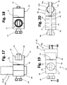
- the two lower articulation systems 14, 15 each comprise a first bracket 16, prearranged for coupling the lower articulation system 14, 15 to a respective portion of the second structure 5 of the frame of the sunbed 2, and an anchorage unit 17, prearranged for anchorage of the lower articulation system 14, 15 to the respective upright element 9, 9'.
- the bracket 16 is a substantially C-shaped bracket, or in any case has a concavity or seat 16' with a shape and dimensions suitable for receiving at least partially a corresponding part of the second structure 5, as is clearly visible, for example, in Figures 13-16 .
- the anchorage unit 17 comprises two similar opposed brackets 18, 19, oriented so as to have respective concavities or seats 20, 21 facing one another, so as to define an internal cavity with a shape and dimensions suitable for receiving a lower end portion of the corresponding upright element 9, 9' (i.e., of the corresponding element 10, 10'), as may be seen, for example, in Figures 17-18 .
- the aforesaid characteristic is in no way limiting in so far as it is possible for the anchorage unit 17 to be formed in a different way, according to any other known technique.
- a screw or similar threaded member
- the central body of which is designated by the number 22, at each lower articulation system 14, 15, which is to extend in a direction transverse to the direction of length of the sunbed 2 and passes, in order, through the corresponding part of the second structure 5 of the sunbed 2, the bracket 16, the anchorage unit 17, and the lower guide element 10, 10' of the corresponding upright element 9, 9', the components 5, 16, 17 and 10 or 10' being provided with corresponding axially aligned through holes, for receiving the screw 22.
- the screw 22 has a head or first end that is widened 23, which is to bear upon the side of the second structure 5 opposite to the bracket 16, and a second end that is threaded, screwed on which is a knob 24, which is to bear upon the wall of the second bracket 19 of the anchorage unit 17 opposite to the bracket 16.
- the bracket 16 is connected in an articulated way to the anchorage unit 17 by means of one or more washers 25 set between the two parts, for example washers made of plastic material. It is to be understood that the shape and dimensions of the brackets 16, 18 and 19 and of the respective concavities or seats 16', 20 and 21 can vary according to the cross-sectional shape and dimensions of the second structure 5 and of the two upright elements 9, 9'.
- the sunshade structure 8 comprises a first longitudinal element 29 and a second longitudinal element 30, which extend in the direction of length of the sunbed 2.
- the sunshade structure 8 further comprises a canvas or the like, where the term "the like" in the way in which it is used here regards any material substantially in sheet form suitable for being used for projecting an area of shade underneath it.
- the material is a canvas, illustrated with a dashed line in Figure 3 and designated by the number 31.
- the canvas 31 is supported between the two longitudinal elements 29, 30.
- the canvas 31 is prearranged for projecting an area of shade on a user resting or lying on the resting surface 6 of the sunbed 2.
- the two longitudinal elements 29, 30 are of a telescopic or in any case extensible/retractable type in such a way that the canvas or the like 31 can be extended/retracted for projecting a more or less extensive area of shade on a user resting or lying on the resting surface 6 of the sunbed 2.
- the level of extension/retraction of the telescopic longitudinal elements 29, 30 can be adjusted or set by means of adjustment or locking systems substantially similar to the adjustment system 12 of the upright elements 9, 9' (and hence, for example, each comprising at least one pushbutton 13' - Figure 4 - associated to one of the telescopic elements, which is able to engage selectively at least one hole provided on the previous telescopic element, or vice versa).
- the two longitudinal elements 29, 30 each comprise four elements, designated in the figures by the references from 32 to 35 in the case of the longitudinal element 29 and from 32' to 35' in the case of the longitudinal element 30, where the elements 32 are substantially guide elements and the elements 33, 34 and 35 are slidable elements.
- This characteristic is in no way limiting, in so far as, in embodiments not illustrated, the two longitudinal elements 29, 30 comprise a greater or smaller number of elements.
- the dimensions of maximum extension of the longitudinal elements 29, 30 can vary according to the length of the sunbed 2.
- the shape of the longitudinal elements 29, 30 and, consequently, of the elements 32-35 and 32'-35' may be of any known type.
- first upright element 9 of the supporting structure 7 is connected in an articulated way to the longitudinal element 29 of the sunshade structure 8 by means of a first upper articulation system 27, and the second upright element 9' of the supporting structure 7 is connected in an articulated way to the longitudinal element 30 of the sunshade structure 8 by means of a second upper articulation system 28.
- the upper articulation systems referred to are configured to enable variation of the angle of the sunshade structure with respect to the upright elements 9, 9', or vice versa. It is to be understood that the two upper articulation systems 27, 28 may be provided with the constructional details of any type of articulation systems known in the art for providing articulated connections.
- the two upper articulation systems 27, 28 may be substantially provided with constructional details similar to those of the two lower articulation systems 14, 15.
- they each comprise a first bracket 36, prearranged for anchorage of the upper articulation system 27, 28 to the respective longitudinal element 29, 30, and an anchorage unit 37, prearranged for anchorage of the upper articulation system 27, 28 to the respective upright element 9, 9'.
- the bracket 36 may be a substantially C-shaped bracket; i.e., it has a concavity or seat 38 with a shape and dimensions suitable for receiving a corresponding part of the longitudinal element 29, 30, or possibly a further element that surrounds it partially (such as a part of the element 44 described hereinafter).
- the anchorage unit 37 comprises two brackets 39, 40 oriented so as to have respective concavities or seats 41, 42 facing one another in order to define an internal cavity with a shape and dimensions suited to receiving an upper end portion of the upright element 9, 9' (i.e., of its upper slidable element 11, 11').
- bracket 36 is connected in an articulated way to the anchorage unit 37 by means of one or more washers 43, for example of a type similar to the ones previously designated by 25. It is to be understood that the shape and dimensions of the brackets 36, 39 and 40 and of the respective concavities or seats 38, 41 and 42 can vary according to the shape and dimensions of the two longitudinal elements 29, 30 and of the two upright elements 9, 9'.
- the device 1 may comprise a transverse strengthening and/or stabilization element 44, in particular in a generally rear portion of the sunshade structure 8.
- the transverse element 44 comprises an axially hollow central part 44a and two tubular end parts 44b and 44b' ( Figure 3 ), which extend in a direction parallel to one another and a direction transverse with respect to the hollow central part 44a, and are provided with holes axially aligned to the cavity of the part 44a.
- the transverse element 44 preferentially extends substantially between the two upper articulation systems 27, 28, and thus in a direction transverse with respect to the direction of the length of the sunbed 2, and passing through the respective tubular end parts is a part of the corresponding longitudinal element 29, 30 of the sunshade structure 8, preferably a stationary part, here represented by the guide element 32, 32'.
- the dimensions of the parts of the hollow transverse element 44 may vary as a function of the distance between the two longitudinal elements 29, 30 and of the cross-sectional dimensions of the latter (of their part 32, 32').
- the shape of the hollow transverse element 44 may be of any type known in the art.
- Screwed to a first threaded end portion of the screw 45, located adjacent to the wall of the first upper articulation system 27 opposite to the hollow transverse element 44 is a first knob 46.
- a second threaded end portion of the screw 45 opposite to the first located adjacent to the wall of the second upper articulation system 28 opposite to the hollow transverse element 44, is a second knob 47.
- transverse element 44 makes it possible to ensure a relatively stable position between the two longitudinal elements 29, 30 in an intermediate position thereof, here a position relatively close to a front end of the corresponding guide elements 32, 32'.
- supporting elements 48, 49, 50 and 51 parallel to the hollow transverse element 44 when this is provided, extend between respective end portions of homologous slidable elements 33 and 33', 34 and 34', 35 and 35'.
- the supporting elements 48, 49, 50, 51 contribute, preferably together with the hollow transverse element 44, to keeping the longitudinal elements 29 and 30 stationary and parallel to one another.
- the supporting elements 48, 49, 50, 51 are also prearranged in order to contribute to supporting the canvas 31.
- each supporting element has its two end portions associated to corresponding end portions of the respective slidable element.
- four supporting elements 48, 49, 50 and 51 are present.
- this characteristic is not to be understood in a limiting sense in so far as it is possible for a greater or smaller number of supporting elements to be present as compared to what has been illustrated.
- the sunshade structure 8 has associated thereto an arrangement for unrolling or stretching out and for rolling up or compacting the canvas 31, in such a way that the sunshade structure 8 and, consequently, the canvas 31 can be extended or retracted in the direction of length of the sunbed 2.
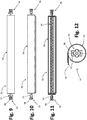
- the arrangement for unrolling/stretching out and rolling up/compacting the canvas 31 basically comprises a winding cylinder or device 52, having an external structure 53 and an internal reel 54.
- the winding cylinder 52 extends in a direction transverse with respect to the direction of the length of the sunbed 2 and in a direction parallel to the supporting elements 48, 49, 50, 51 and to the hollow transverse element 44.
- the winding cylinder 52 is anchored to a rear end portion of the two longitudinal elements 29, 30, in particular of their guide elements 32, 32', by means of a first connection system 55 and a second connection system 56, respectively.
- the two connection systems 55, 56 may each comprise a C-shaped bracket 57, prearranged for receiving a rear end portion of the longitudinal element 29, 30 and a knob 58 screwed on a corresponding screw that projects from a longitudinal end of the cylinder 52 and passing through a hole in the corresponding longitudinal element 29, 30 (i.e., in its guide element 32, 32').
- the external structure 53 of the winding cylinder 52 is hence fixed, and has a slit that extends throughout the length of the winding cylinder 52, through which the canvas 31 enters/exits in such a way that it can be wound on the reel 54 or unwound therefrom.
- a tensile force applied thereon causes rotation of the reel 54 countering the elastic-return element (for example, a spring) until the desired degree of extension/retraction is reached according to the area of shade projected.
- a user resting or lying on the resting surface 6 of the sunbed 2 who wishes to increase or reduce the extent of the area of shade projected by the sunshade structure 8 of the sunshade device 1, acts so as to vary the degree of extension/retraction of the telescopic longitudinal elements 29, 30.
- degree of extension and assuming that the front end of the canvas is anchored - for example - to the supporting element 51 - rotation is consequently triggered in one direction or in the other of the reel 54 inside the winding cylinder 52 (thanks to the action of the corresponding return element, or else countering its action) in such a way as to wind the canvas 31 on the reel 54 or unwind it therefrom according to the change made.
- the position of extension of the telescopic longitudinal elements 29, 30 can be established, as has been mentioned, via adjustment or locking systems in themselves known, which can be operated by the user. It is also possible to prearrange the telescopic longitudinal elements 29, 30 in such a way that the corresponding parts, which are able to slide with respect to one another are coupled with sufficient friction to cause the parts themselves to maintain the position assigned, notwithstanding the action of the return element inside the arrangement for unrolling/rolling up the canvas. In other words, the action of the recall element will not be such as to overcome the friction between the sliding parts.
- the transverse element 44 and the supporting elements 48, 49, 50 and 51 in addition to supporting the canvas 31, cause the two longitudinal elements 29, 30 to be maintained always parallel to one another and so that there is no risk of the end portions opposite to the winding cylinder 52 folding one another as a result of lack of support.
- the user is also able to increase or reduce the distance between the supporting surface 6 and the sunshade structure 8 by acting on the adjustment system 12 and hence by adjusting sliding of the telescopic upright elements 9, 9'.
- the articulated connection of the supporting structure 7 both to the sunbed 2, by means of the lower articulation systems 14 and 15, and to the sunshade structure 8, by means of the upper articulation systems 27 and 28, means that it is possible to bring the sunshade structure 8 adjacent to the resting surface 6 of the sunbed 2. This is particularly advantageous when it is desired to reduce the volume occupied by the sunbed 2 and by the sunshade device 1 mounted thereon, for example when it is necessary to displace the sunbed 2 or store it away.
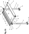
- Figure 22 exemplifies the case of a sunbed 2 with the sunshade device 1 in an operating configuration substantially resembling the one visible in Figure 21 , whereas Figure 22 shows how, starting from this position and acting on the lower and upper articulation systems, it is possible to "knock down" the overall structure of the sunshade device 1 onto the sunbed 2.
- the sunshade structure 8 itself is configured to provide an arrangement for unrolling or stretching out and for rolling up or compacting the canvas 31.
- the aforesaid arrangement for unrolling/stretching out and for rolling up/compacting comprises the canvas 31 itself, which has a structure configured or prearranged for folding on itself.
- FIG. 24 and 25 An example of this sort is exemplified in Figures 24 and 25 , where the canvas 31 is of a pleated or undulated type, or in any case arranged for folding at least in part on itself, in particular in the passage from the extended position to the retracted position of the telescopic or extensible/retractable structure.
- the canvas 31 has for this purpose a series of pre-set folding lines, transverse to the direction of extension of the structure 8, i.e., with a substantially concertina structure.
- the canvas 31 can assume an extended configuration (visible in Figure 24 ) and a compact configuration (visible in Figure 25 ); in the configuration of Figure 25 , the aforesaid folding lines enable the canvas 31 to fold on itself in order to assume the compact configuration.
- the canvas 31 it is preferable for the canvas 31 to be constrained also via two or more wires, strings, or cords, interwoven in the canvas itself, i.e., passing in its passages, so as to extend in the direction of extension of the canvas.
- the aforesaid wires for example two lateral ones and at least an intermediate one (with respect to the dimension of width of the canvas) have the purpose of guiding unwinding and compacting of the canvas, preventing any irregular deformations thereof, for example oblique, during opening and closing.
- the front ends of the aforementioned wires can be anchored to a rigid transverse element - designated as a whole by 31" - associated to the front region of the telescopic structure 8, this element possibly also being constituted by the element 51 of Figure 3 .
- the rear end of each of the wires 31' is instead preferably associated to a winder device 52, so that the wires themselves can be unwound or wound with respect thereto.
- Figure 26 illustrates another example of embodiment, where the canvas 31 is arranged on the corresponding telescopic structure so as to fold at least partially on itself when the structure is retracted.
- the canvas 31 may be locally constrained to the elements 48, 49, 50 and 51 so that, in the retracted position of the telescopic structure, the portions of canvas comprised between the elements 48-49, 49-50 and 50-51 form bends 31a.
- a winder device is consequently not necessary, with the rear end of the canvas 31 that is preferentially constrained in a rear area of the telescopic structure, for example to a transverse element 52' that extends between the two parallel longitudinal elements 32, 32'.
- the portion 31b of the canvas 31 that extends between the aforesaid constraint element 52' and the element 48 may remain in a substantially plane condition.
- the sunshade device forming the subject of the present invention is characterized by a greater simplicity of use as compared to the solutions currently available for adjusting the extent of the area of shade projected by a canvas or the like on a sunbed or the like.
- sunshade device forming the subject of the present invention lies in its versatility of use, since it can be easily mounted on structures different from one another, such as sunbeds, deck-chairs, or recliners.
- the canvas 31 has a front area fixed with respect to a front part of the telescopic sunshade structure 8 (for example, the element 51 of Figure 3 ) has been described, but this does not of course constitute an essential characteristic.
Landscapes
- Health & Medical Sciences (AREA)
- Dentistry (AREA)
- General Health & Medical Sciences (AREA)
- Building Awnings And Sunshades (AREA)
- Vehicle Step Arrangements And Article Storage (AREA)
- Arrangements Of Lighting Devices For Vehicle Interiors, Mounting And Supporting Thereof, Circuits Therefore (AREA)
- Window Of Vehicle (AREA)
Applications Claiming Priority (1)
| Application Number | Priority Date | Filing Date | Title |
|---|---|---|---|
| IT202020000002071U IT202000002071U1 (it) | 2020-04-30 | 2020-04-30 | Dispositivo parasole |
Publications (1)
| Publication Number | Publication Date |
|---|---|
| EP3903643A1 true EP3903643A1 (fr) | 2021-11-03 |
Family
ID=76269563
Family Applications (1)
| Application Number | Title | Priority Date | Filing Date |
|---|---|---|---|
| EP21170997.7A Pending EP3903643A1 (fr) | 2020-04-30 | 2021-04-28 | Dispositif parasoleil |
Country Status (2)
| Country | Link |
|---|---|
| EP (1) | EP3903643A1 (fr) |
| IT (1) | IT202000002071U1 (fr) |
Cited By (1)
| Publication number | Priority date | Publication date | Assignee | Title |
|---|---|---|---|---|
| CN115584881A (zh) * | 2022-11-02 | 2023-01-10 | 云南电网有限责任公司德宏供电局 | 一种露天断路器机构检修遮雨工棚 |
Citations (6)
| Publication number | Priority date | Publication date | Assignee | Title |
|---|---|---|---|---|
| US5096257A (en) * | 1991-03-26 | 1992-03-17 | Brian L. Clark | Sunshade apparatus for chair |
| US5135281A (en) * | 1991-06-28 | 1992-08-04 | Edward Pappalardo | Sunshade |
| US5797650A (en) * | 1997-08-20 | 1998-08-25 | Gonzalez, Jr.; Ralph | Sun shade attachment |
| US6244286B1 (en) * | 1999-12-23 | 2001-06-12 | Aleandro M. Russo | Collapsible canopy device |
| KR20100104459A (ko) * | 2009-03-18 | 2010-09-29 | 노호양 | 의자용 접철식 차양장치 |
| US20110175407A1 (en) | 2010-01-19 | 2011-07-21 | Sergey Sharapov | Beach chair with sun protective device |
-
2020
- 2020-04-30 IT IT202020000002071U patent/IT202000002071U1/it unknown
-
2021
- 2021-04-28 EP EP21170997.7A patent/EP3903643A1/fr active Pending
Patent Citations (6)
| Publication number | Priority date | Publication date | Assignee | Title |
|---|---|---|---|---|
| US5096257A (en) * | 1991-03-26 | 1992-03-17 | Brian L. Clark | Sunshade apparatus for chair |
| US5135281A (en) * | 1991-06-28 | 1992-08-04 | Edward Pappalardo | Sunshade |
| US5797650A (en) * | 1997-08-20 | 1998-08-25 | Gonzalez, Jr.; Ralph | Sun shade attachment |
| US6244286B1 (en) * | 1999-12-23 | 2001-06-12 | Aleandro M. Russo | Collapsible canopy device |
| KR20100104459A (ko) * | 2009-03-18 | 2010-09-29 | 노호양 | 의자용 접철식 차양장치 |
| US20110175407A1 (en) | 2010-01-19 | 2011-07-21 | Sergey Sharapov | Beach chair with sun protective device |
Cited By (2)
| Publication number | Priority date | Publication date | Assignee | Title |
|---|---|---|---|---|
| CN115584881A (zh) * | 2022-11-02 | 2023-01-10 | 云南电网有限责任公司德宏供电局 | 一种露天断路器机构检修遮雨工棚 |
| CN115584881B (zh) * | 2022-11-02 | 2025-10-10 | 云南电网有限责任公司德宏供电局 | 一种露天断路器机构检修遮雨工棚 |
Also Published As
| Publication number | Publication date |
|---|---|
| IT202000002071U1 (it) | 2021-10-30 |
Similar Documents
| Publication | Publication Date | Title |
|---|---|---|
| RU2407868C2 (ru) | Покрывающая система | |
| US5446932A (en) | Folding wall bed | |
| CA2277989C (fr) | Structure pour abri pare-soleil | |
| DE69833867T2 (de) | Regenschirm mit seitlicher stütze zum neigen und öffnen des schirms | |
| US4635667A (en) | Sun protection canopy | |
| AU728101B2 (en) | Roller assembly, table assembly and modesty screen | |
| AU2005317864B2 (en) | A covering system | |
| US7431388B2 (en) | Chair with a built-in sun-protective device | |
| US5109556A (en) | Camp cot with adjustable to tensioning | |
| AU2002233071B2 (en) | Retractable self rolling blind awning or cover apparatus | |
| AU2002233071A1 (en) | Retractable Self Rolling Blind Awning or Cover Apparatus | |
| CA2804994C (fr) | Appareil de levage | |
| US3487842A (en) | Privacy/windbreak screen | |
| IT202000002071U1 (it) | Dispositivo parasole | |
| US20050103371A1 (en) | Retractable terrace canopy | |
| WO2003040490A1 (fr) | Mecanisme pour lever un element de protection suspendu | |
| WO2000009831A1 (fr) | Dais d'ombre | |
| KR101614648B1 (ko) | 멀티 차양 파라솔 | |
| WO2007034047A2 (fr) | Systeme de store horizontal ou incline a support escamotable | |
| KR100350583B1 (ko) | 휴대용 절첩식 침대의 시트 굴곡 방지장치 | |
| CN221236504U (zh) | 一种遮阳防晒帐篷 | |
| CA2818008A1 (fr) | Toit pour voilier retractable, auvent/dispositif de protection contre la pluie fixe au tangon d'un voilier | |
| CN216220828U (zh) | 一种可调节仰靠角度的沙滩椅 | |
| KR200212423Y1 (ko) | 휴대용 절첩식 침대의 시트 굴곡 방지장치 | |
| AU681134B2 (en) | Demountable structure |
Legal Events
| Date | Code | Title | Description |
|---|---|---|---|
| PUAI | Public reference made under article 153(3) epc to a published international application that has entered the european phase |
Free format text: ORIGINAL CODE: 0009012 |
|
| STAA | Information on the status of an ep patent application or granted ep patent |
Free format text: STATUS: THE APPLICATION HAS BEEN PUBLISHED |
|
| AK | Designated contracting states |
Kind code of ref document: A1 Designated state(s): AL AT BE BG CH CY CZ DE DK EE ES FI FR GB GR HR HU IE IS IT LI LT LU LV MC MK MT NL NO PL PT RO RS SE SI SK SM TR |
|
| B565 | Issuance of search results under rule 164(2) epc |
Effective date: 20210923 |
|
| STAA | Information on the status of an ep patent application or granted ep patent |
Free format text: STATUS: REQUEST FOR EXAMINATION WAS MADE |
|
| 17P | Request for examination filed |
Effective date: 20220503 |
|
| RBV | Designated contracting states (corrected) |
Designated state(s): AL AT BE BG CH CY CZ DE DK EE ES FI FR GB GR HR HU IE IS IT LI LT LU LV MC MK MT NL NO PL PT RO RS SE SI SK SM TR |
|
| STAA | Information on the status of an ep patent application or granted ep patent |
Free format text: STATUS: EXAMINATION IS IN PROGRESS |
|
| 17Q | First examination report despatched |
Effective date: 20230607 |