EP3903699B1 - Chirurgische zielvorrichtung - Google Patents
Chirurgische zielvorrichtung Download PDFInfo
- Publication number
- EP3903699B1 EP3903699B1 EP21174302.6A EP21174302A EP3903699B1 EP 3903699 B1 EP3903699 B1 EP 3903699B1 EP 21174302 A EP21174302 A EP 21174302A EP 3903699 B1 EP3903699 B1 EP 3903699B1
- Authority
- EP
- European Patent Office
- Prior art keywords
- guidance
- targeting device
- hole
- surgical targeting
- bottom portion
- Prior art date
- Legal status (The legal status is an assumption and is not a legal conclusion. Google has not performed a legal analysis and makes no representation as to the accuracy of the status listed.)
- Active
Links
Images





Classifications
-
- A—HUMAN NECESSITIES
- A61—MEDICAL OR VETERINARY SCIENCE; HYGIENE
- A61F—FILTERS IMPLANTABLE INTO BLOOD VESSELS; PROSTHESES; DEVICES PROVIDING PATENCY TO, OR PREVENTING COLLAPSING OF, TUBULAR STRUCTURES OF THE BODY, e.g. STENTS; ORTHOPAEDIC, NURSING OR CONTRACEPTIVE DEVICES; FOMENTATION; TREATMENT OR PROTECTION OF EYES OR EARS; BANDAGES, DRESSINGS OR ABSORBENT PADS; FIRST-AID KITS
- A61F2/00—Filters implantable into blood vessels; Prostheses, i.e. artificial substitutes or replacements for parts of the body; Appliances for connecting them with the body; Devices providing patency to, or preventing collapsing of, tubular structures of the body, e.g. stents
- A61F2/02—Prostheses implantable into the body
- A61F2/30—Joints
- A61F2/46—Special tools for implanting artificial joints
- A61F2/4684—Trial or dummy prostheses
-
- A—HUMAN NECESSITIES
- A61—MEDICAL OR VETERINARY SCIENCE; HYGIENE
- A61F—FILTERS IMPLANTABLE INTO BLOOD VESSELS; PROSTHESES; DEVICES PROVIDING PATENCY TO, OR PREVENTING COLLAPSING OF, TUBULAR STRUCTURES OF THE BODY, e.g. STENTS; ORTHOPAEDIC, NURSING OR CONTRACEPTIVE DEVICES; FOMENTATION; TREATMENT OR PROTECTION OF EYES OR EARS; BANDAGES, DRESSINGS OR ABSORBENT PADS; FIRST-AID KITS
- A61F2/00—Filters implantable into blood vessels; Prostheses, i.e. artificial substitutes or replacements for parts of the body; Appliances for connecting them with the body; Devices providing patency to, or preventing collapsing of, tubular structures of the body, e.g. stents
- A61F2/02—Prostheses implantable into the body
- A61F2/30—Joints
- A61F2/46—Special tools for implanting artificial joints
- A61F2/4603—Special tools for implanting artificial joints for insertion or extraction of endoprosthetic joints or of accessories thereof
- A61F2/4607—Special tools for implanting artificial joints for insertion or extraction of endoprosthetic joints or of accessories thereof of hip femoral endoprostheses
-
- A—HUMAN NECESSITIES
- A61—MEDICAL OR VETERINARY SCIENCE; HYGIENE
- A61B—DIAGNOSIS; SURGERY; IDENTIFICATION
- A61B17/00—Surgical instruments, devices or methods
- A61B17/16—Instruments for performing osteoclasis; Drills or chisels for bones; Trepans
- A61B17/17—Guides or aligning means for drills, mills, pins or wires
- A61B17/1739—Guides or aligning means for drills, mills, pins or wires specially adapted for particular parts of the body
- A61B17/1782—Guides or aligning means for drills, mills, pins or wires specially adapted for particular parts of the body for the hand or wrist
-
- A—HUMAN NECESSITIES
- A61—MEDICAL OR VETERINARY SCIENCE; HYGIENE
- A61B—DIAGNOSIS; SURGERY; IDENTIFICATION
- A61B17/00—Surgical instruments, devices or methods
- A61B17/56—Surgical instruments or methods for treatment of bones or joints; Devices specially adapted therefor
- A61B17/58—Surgical instruments or methods for treatment of bones or joints; Devices specially adapted therefor for osteosynthesis, e.g. bone plates, screws or setting implements
- A61B17/88—Osteosynthesis instruments; Methods or means for implanting or extracting internal or external fixation devices
- A61B17/90—Guides therefor
-
- A—HUMAN NECESSITIES
- A61—MEDICAL OR VETERINARY SCIENCE; HYGIENE
- A61F—FILTERS IMPLANTABLE INTO BLOOD VESSELS; PROSTHESES; DEVICES PROVIDING PATENCY TO, OR PREVENTING COLLAPSING OF, TUBULAR STRUCTURES OF THE BODY, e.g. STENTS; ORTHOPAEDIC, NURSING OR CONTRACEPTIVE DEVICES; FOMENTATION; TREATMENT OR PROTECTION OF EYES OR EARS; BANDAGES, DRESSINGS OR ABSORBENT PADS; FIRST-AID KITS
- A61F2/00—Filters implantable into blood vessels; Prostheses, i.e. artificial substitutes or replacements for parts of the body; Appliances for connecting them with the body; Devices providing patency to, or preventing collapsing of, tubular structures of the body, e.g. stents
- A61F2/02—Prostheses implantable into the body
- A61F2/30—Joints
- A61F2/42—Joints for wrists or ankles; for hands, e.g. fingers; for feet, e.g. toes
- A61F2/4261—Joints for wrists or ankles; for hands, e.g. fingers; for feet, e.g. toes for wrists
-
- A—HUMAN NECESSITIES
- A61—MEDICAL OR VETERINARY SCIENCE; HYGIENE
- A61F—FILTERS IMPLANTABLE INTO BLOOD VESSELS; PROSTHESES; DEVICES PROVIDING PATENCY TO, OR PREVENTING COLLAPSING OF, TUBULAR STRUCTURES OF THE BODY, e.g. STENTS; ORTHOPAEDIC, NURSING OR CONTRACEPTIVE DEVICES; FOMENTATION; TREATMENT OR PROTECTION OF EYES OR EARS; BANDAGES, DRESSINGS OR ABSORBENT PADS; FIRST-AID KITS
- A61F2/00—Filters implantable into blood vessels; Prostheses, i.e. artificial substitutes or replacements for parts of the body; Appliances for connecting them with the body; Devices providing patency to, or preventing collapsing of, tubular structures of the body, e.g. stents
- A61F2/02—Prostheses implantable into the body
- A61F2/30—Joints
- A61F2/46—Special tools for implanting artificial joints
- A61F2/4603—Special tools for implanting artificial joints for insertion or extraction of endoprosthetic joints or of accessories thereof
- A61F2/4609—Special tools for implanting artificial joints for insertion or extraction of endoprosthetic joints or of accessories thereof of acetabular cups
-
- A—HUMAN NECESSITIES
- A61—MEDICAL OR VETERINARY SCIENCE; HYGIENE
- A61B—DIAGNOSIS; SURGERY; IDENTIFICATION
- A61B17/00—Surgical instruments, devices or methods
- A61B17/16—Instruments for performing osteoclasis; Drills or chisels for bones; Trepans
- A61B17/1662—Instruments for performing osteoclasis; Drills or chisels for bones; Trepans for particular parts of the body
- A61B17/1686—Instruments for performing osteoclasis; Drills or chisels for bones; Trepans for particular parts of the body for the hand or wrist
-
- A—HUMAN NECESSITIES
- A61—MEDICAL OR VETERINARY SCIENCE; HYGIENE
- A61B—DIAGNOSIS; SURGERY; IDENTIFICATION
- A61B17/00—Surgical instruments, devices or methods
- A61B17/16—Instruments for performing osteoclasis; Drills or chisels for bones; Trepans
- A61B17/1697—Instruments for performing osteoclasis; Drills or chisels for bones; Trepans specially adapted for wire insertion
-
- A—HUMAN NECESSITIES
- A61—MEDICAL OR VETERINARY SCIENCE; HYGIENE
- A61B—DIAGNOSIS; SURGERY; IDENTIFICATION
- A61B17/00—Surgical instruments, devices or methods
- A61B17/56—Surgical instruments or methods for treatment of bones or joints; Devices specially adapted therefor
- A61B17/58—Surgical instruments or methods for treatment of bones or joints; Devices specially adapted therefor for osteosynthesis, e.g. bone plates, screws or setting implements
- A61B17/68—Internal fixation devices, including fasteners and spinal fixators, even if a part thereof projects from the skin
- A61B17/84—Fasteners therefor or fasteners being internal fixation devices
- A61B17/846—Nails or pins, i.e. anchors without movable parts, holding by friction only, with or without structured surface
- A61B17/848—Kirschner wires, i.e. thin, long nails
-
- A—HUMAN NECESSITIES
- A61—MEDICAL OR VETERINARY SCIENCE; HYGIENE
- A61B—DIAGNOSIS; SURGERY; IDENTIFICATION
- A61B17/00—Surgical instruments, devices or methods
- A61B17/56—Surgical instruments or methods for treatment of bones or joints; Devices specially adapted therefor
- A61B17/58—Surgical instruments or methods for treatment of bones or joints; Devices specially adapted therefor for osteosynthesis, e.g. bone plates, screws or setting implements
- A61B17/88—Osteosynthesis instruments; Methods or means for implanting or extracting internal or external fixation devices
- A61B17/8897—Guide wires or guide pins
-
- A—HUMAN NECESSITIES
- A61—MEDICAL OR VETERINARY SCIENCE; HYGIENE
- A61B—DIAGNOSIS; SURGERY; IDENTIFICATION
- A61B17/00—Surgical instruments, devices or methods
- A61B17/16—Instruments for performing osteoclasis; Drills or chisels for bones; Trepans
- A61B2017/1602—Mills
-
- A—HUMAN NECESSITIES
- A61—MEDICAL OR VETERINARY SCIENCE; HYGIENE
- A61F—FILTERS IMPLANTABLE INTO BLOOD VESSELS; PROSTHESES; DEVICES PROVIDING PATENCY TO, OR PREVENTING COLLAPSING OF, TUBULAR STRUCTURES OF THE BODY, e.g. STENTS; ORTHOPAEDIC, NURSING OR CONTRACEPTIVE DEVICES; FOMENTATION; TREATMENT OR PROTECTION OF EYES OR EARS; BANDAGES, DRESSINGS OR ABSORBENT PADS; FIRST-AID KITS
- A61F2/00—Filters implantable into blood vessels; Prostheses, i.e. artificial substitutes or replacements for parts of the body; Appliances for connecting them with the body; Devices providing patency to, or preventing collapsing of, tubular structures of the body, e.g. stents
- A61F2/02—Prostheses implantable into the body
- A61F2/30—Joints
- A61F2/32—Joints for the hip
-
- A—HUMAN NECESSITIES
- A61—MEDICAL OR VETERINARY SCIENCE; HYGIENE
- A61F—FILTERS IMPLANTABLE INTO BLOOD VESSELS; PROSTHESES; DEVICES PROVIDING PATENCY TO, OR PREVENTING COLLAPSING OF, TUBULAR STRUCTURES OF THE BODY, e.g. STENTS; ORTHOPAEDIC, NURSING OR CONTRACEPTIVE DEVICES; FOMENTATION; TREATMENT OR PROTECTION OF EYES OR EARS; BANDAGES, DRESSINGS OR ABSORBENT PADS; FIRST-AID KITS
- A61F2/00—Filters implantable into blood vessels; Prostheses, i.e. artificial substitutes or replacements for parts of the body; Appliances for connecting them with the body; Devices providing patency to, or preventing collapsing of, tubular structures of the body, e.g. stents
- A61F2/02—Prostheses implantable into the body
- A61F2/30—Joints
- A61F2002/30001—Additional features of subject-matter classified in A61F2/28, A61F2/30 and subgroups thereof
- A61F2002/30108—Shapes
- A61F2002/30199—Three-dimensional shapes
- A61F2002/30205—Three-dimensional shapes conical
-
- A—HUMAN NECESSITIES
- A61—MEDICAL OR VETERINARY SCIENCE; HYGIENE
- A61F—FILTERS IMPLANTABLE INTO BLOOD VESSELS; PROSTHESES; DEVICES PROVIDING PATENCY TO, OR PREVENTING COLLAPSING OF, TUBULAR STRUCTURES OF THE BODY, e.g. STENTS; ORTHOPAEDIC, NURSING OR CONTRACEPTIVE DEVICES; FOMENTATION; TREATMENT OR PROTECTION OF EYES OR EARS; BANDAGES, DRESSINGS OR ABSORBENT PADS; FIRST-AID KITS
- A61F2/00—Filters implantable into blood vessels; Prostheses, i.e. artificial substitutes or replacements for parts of the body; Appliances for connecting them with the body; Devices providing patency to, or preventing collapsing of, tubular structures of the body, e.g. stents
- A61F2/02—Prostheses implantable into the body
- A61F2/30—Joints
- A61F2002/30001—Additional features of subject-matter classified in A61F2/28, A61F2/30 and subgroups thereof
- A61F2002/30316—The prosthesis having different structural features at different locations within the same prosthesis; Connections between prosthetic parts; Special structural features of bone or joint prostheses not otherwise provided for
- A61F2002/30329—Connections or couplings between prosthetic parts, e.g. between modular parts; Connecting elements
- A61F2002/30462—Connections or couplings between prosthetic parts, e.g. between modular parts; Connecting elements retained or tied with a rope, string, thread, wire or cable
-
- A—HUMAN NECESSITIES
- A61—MEDICAL OR VETERINARY SCIENCE; HYGIENE
- A61F—FILTERS IMPLANTABLE INTO BLOOD VESSELS; PROSTHESES; DEVICES PROVIDING PATENCY TO, OR PREVENTING COLLAPSING OF, TUBULAR STRUCTURES OF THE BODY, e.g. STENTS; ORTHOPAEDIC, NURSING OR CONTRACEPTIVE DEVICES; FOMENTATION; TREATMENT OR PROTECTION OF EYES OR EARS; BANDAGES, DRESSINGS OR ABSORBENT PADS; FIRST-AID KITS
- A61F2/00—Filters implantable into blood vessels; Prostheses, i.e. artificial substitutes or replacements for parts of the body; Appliances for connecting them with the body; Devices providing patency to, or preventing collapsing of, tubular structures of the body, e.g. stents
- A61F2/02—Prostheses implantable into the body
- A61F2/30—Joints
- A61F2002/30001—Additional features of subject-matter classified in A61F2/28, A61F2/30 and subgroups thereof
- A61F2002/30621—Features concerning the anatomical functioning or articulation of the prosthetic joint
- A61F2002/30649—Ball-and-socket joints
-
- A—HUMAN NECESSITIES
- A61—MEDICAL OR VETERINARY SCIENCE; HYGIENE
- A61F—FILTERS IMPLANTABLE INTO BLOOD VESSELS; PROSTHESES; DEVICES PROVIDING PATENCY TO, OR PREVENTING COLLAPSING OF, TUBULAR STRUCTURES OF THE BODY, e.g. STENTS; ORTHOPAEDIC, NURSING OR CONTRACEPTIVE DEVICES; FOMENTATION; TREATMENT OR PROTECTION OF EYES OR EARS; BANDAGES, DRESSINGS OR ABSORBENT PADS; FIRST-AID KITS
- A61F2/00—Filters implantable into blood vessels; Prostheses, i.e. artificial substitutes or replacements for parts of the body; Appliances for connecting them with the body; Devices providing patency to, or preventing collapsing of, tubular structures of the body, e.g. stents
- A61F2/02—Prostheses implantable into the body
- A61F2/30—Joints
- A61F2002/30001—Additional features of subject-matter classified in A61F2/28, A61F2/30 and subgroups thereof
- A61F2002/30667—Features concerning an interaction with the environment or a particular use of the prosthesis
- A61F2002/30672—Features concerning an interaction with the environment or a particular use of the prosthesis temporary
-
- A—HUMAN NECESSITIES
- A61—MEDICAL OR VETERINARY SCIENCE; HYGIENE
- A61F—FILTERS IMPLANTABLE INTO BLOOD VESSELS; PROSTHESES; DEVICES PROVIDING PATENCY TO, OR PREVENTING COLLAPSING OF, TUBULAR STRUCTURES OF THE BODY, e.g. STENTS; ORTHOPAEDIC, NURSING OR CONTRACEPTIVE DEVICES; FOMENTATION; TREATMENT OR PROTECTION OF EYES OR EARS; BANDAGES, DRESSINGS OR ABSORBENT PADS; FIRST-AID KITS
- A61F2/00—Filters implantable into blood vessels; Prostheses, i.e. artificial substitutes or replacements for parts of the body; Appliances for connecting them with the body; Devices providing patency to, or preventing collapsing of, tubular structures of the body, e.g. stents
- A61F2/02—Prostheses implantable into the body
- A61F2/30—Joints
- A61F2/30767—Special external or bone-contacting surface, e.g. coating for improving bone ingrowth
- A61F2/30771—Special external or bone-contacting surface, e.g. coating for improving bone ingrowth applied in original prostheses, e.g. holes or grooves
- A61F2002/30841—Sharp anchoring protrusions for impaction into the bone, e.g. sharp pins, spikes
-
- A—HUMAN NECESSITIES
- A61—MEDICAL OR VETERINARY SCIENCE; HYGIENE
- A61F—FILTERS IMPLANTABLE INTO BLOOD VESSELS; PROSTHESES; DEVICES PROVIDING PATENCY TO, OR PREVENTING COLLAPSING OF, TUBULAR STRUCTURES OF THE BODY, e.g. STENTS; ORTHOPAEDIC, NURSING OR CONTRACEPTIVE DEVICES; FOMENTATION; TREATMENT OR PROTECTION OF EYES OR EARS; BANDAGES, DRESSINGS OR ABSORBENT PADS; FIRST-AID KITS
- A61F2/00—Filters implantable into blood vessels; Prostheses, i.e. artificial substitutes or replacements for parts of the body; Appliances for connecting them with the body; Devices providing patency to, or preventing collapsing of, tubular structures of the body, e.g. stents
- A61F2/02—Prostheses implantable into the body
- A61F2/30—Joints
- A61F2/30767—Special external or bone-contacting surface, e.g. coating for improving bone ingrowth
- A61F2/30771—Special external or bone-contacting surface, e.g. coating for improving bone ingrowth applied in original prostheses, e.g. holes or grooves
- A61F2002/30904—Special external or bone-contacting surface, e.g. coating for improving bone ingrowth applied in original prostheses, e.g. holes or grooves serrated profile, i.e. saw-toothed
-
- A—HUMAN NECESSITIES
- A61—MEDICAL OR VETERINARY SCIENCE; HYGIENE
- A61F—FILTERS IMPLANTABLE INTO BLOOD VESSELS; PROSTHESES; DEVICES PROVIDING PATENCY TO, OR PREVENTING COLLAPSING OF, TUBULAR STRUCTURES OF THE BODY, e.g. STENTS; ORTHOPAEDIC, NURSING OR CONTRACEPTIVE DEVICES; FOMENTATION; TREATMENT OR PROTECTION OF EYES OR EARS; BANDAGES, DRESSINGS OR ABSORBENT PADS; FIRST-AID KITS
- A61F2/00—Filters implantable into blood vessels; Prostheses, i.e. artificial substitutes or replacements for parts of the body; Appliances for connecting them with the body; Devices providing patency to, or preventing collapsing of, tubular structures of the body, e.g. stents
- A61F2/02—Prostheses implantable into the body
- A61F2/30—Joints
- A61F2/42—Joints for wrists or ankles; for hands, e.g. fingers; for feet, e.g. toes
- A61F2/4261—Joints for wrists or ankles; for hands, e.g. fingers; for feet, e.g. toes for wrists
- A61F2002/4271—Carpal bones
- A61F2002/4274—Distal carpal row, i.e. bones adjacent the metacarpal bones
-
- A—HUMAN NECESSITIES
- A61—MEDICAL OR VETERINARY SCIENCE; HYGIENE
- A61F—FILTERS IMPLANTABLE INTO BLOOD VESSELS; PROSTHESES; DEVICES PROVIDING PATENCY TO, OR PREVENTING COLLAPSING OF, TUBULAR STRUCTURES OF THE BODY, e.g. STENTS; ORTHOPAEDIC, NURSING OR CONTRACEPTIVE DEVICES; FOMENTATION; TREATMENT OR PROTECTION OF EYES OR EARS; BANDAGES, DRESSINGS OR ABSORBENT PADS; FIRST-AID KITS
- A61F2/00—Filters implantable into blood vessels; Prostheses, i.e. artificial substitutes or replacements for parts of the body; Appliances for connecting them with the body; Devices providing patency to, or preventing collapsing of, tubular structures of the body, e.g. stents
- A61F2/02—Prostheses implantable into the body
- A61F2/30—Joints
- A61F2/42—Joints for wrists or ankles; for hands, e.g. fingers; for feet, e.g. toes
- A61F2/4261—Joints for wrists or ankles; for hands, e.g. fingers; for feet, e.g. toes for wrists
- A61F2002/4271—Carpal bones
- A61F2002/4274—Distal carpal row, i.e. bones adjacent the metacarpal bones
- A61F2002/4276—Trapezium
-
- A—HUMAN NECESSITIES
- A61—MEDICAL OR VETERINARY SCIENCE; HYGIENE
- A61F—FILTERS IMPLANTABLE INTO BLOOD VESSELS; PROSTHESES; DEVICES PROVIDING PATENCY TO, OR PREVENTING COLLAPSING OF, TUBULAR STRUCTURES OF THE BODY, e.g. STENTS; ORTHOPAEDIC, NURSING OR CONTRACEPTIVE DEVICES; FOMENTATION; TREATMENT OR PROTECTION OF EYES OR EARS; BANDAGES, DRESSINGS OR ABSORBENT PADS; FIRST-AID KITS
- A61F2/00—Filters implantable into blood vessels; Prostheses, i.e. artificial substitutes or replacements for parts of the body; Appliances for connecting them with the body; Devices providing patency to, or preventing collapsing of, tubular structures of the body, e.g. stents
- A61F2/02—Prostheses implantable into the body
- A61F2/30—Joints
- A61F2/46—Special tools for implanting artificial joints
- A61F2/4657—Measuring instruments used for implanting artificial joints
- A61F2002/4662—Measuring instruments used for implanting artificial joints for measuring penetration depth
-
- A—HUMAN NECESSITIES
- A61—MEDICAL OR VETERINARY SCIENCE; HYGIENE
- A61F—FILTERS IMPLANTABLE INTO BLOOD VESSELS; PROSTHESES; DEVICES PROVIDING PATENCY TO, OR PREVENTING COLLAPSING OF, TUBULAR STRUCTURES OF THE BODY, e.g. STENTS; ORTHOPAEDIC, NURSING OR CONTRACEPTIVE DEVICES; FOMENTATION; TREATMENT OR PROTECTION OF EYES OR EARS; BANDAGES, DRESSINGS OR ABSORBENT PADS; FIRST-AID KITS
- A61F2/00—Filters implantable into blood vessels; Prostheses, i.e. artificial substitutes or replacements for parts of the body; Appliances for connecting them with the body; Devices providing patency to, or preventing collapsing of, tubular structures of the body, e.g. stents
- A61F2/02—Prostheses implantable into the body
- A61F2/30—Joints
- A61F2/46—Special tools for implanting artificial joints
- A61F2002/4687—Mechanical guides for implantation instruments
Definitions
- the present disclosure provides a surgical targeting device for assisting placement of an elongated guidance member in a bone.
- the present disclosure further provides a surgical system comprising the surgical targeting device and at a least a socket part of a ball and socket joint implant. Also described herein although not falling within the scope of the claims is a surgical method of using the surgical targeting device.
- a K-wire (also referred to as Kirschner wire) is an elongated guidance member that is typically a pointed stainless-steel wire used in orthopedic surgery for temporary fixation to a bone. K-wires are used for many surgical purposes.
- a K-wire is temporarily fixed in a trapezium bone at a desired location and orientation to serve as guidance for a reamer sliding onto the K-wire.
- the reamer can then be moved from the free end of the K-wire protruding from the respective bone towards the bone to ream the bone at the desired location and orientation of the K-wire.
- the reamer is pulled back and removed from the K-wire. Afterwards, the K-wire is removed from the bone to allow placement of a joint prosthesis cup (i.e., a socket part of a ball and socket joint implant) in the bone recess created by the reamer.
- a joint prosthesis cup i.e., a socket part of a ball and socket joint implant
- EP 3 210 550 A1 describes a guide member for guiding through a K-wire to an implantation site.
- the guide member comprises a head portion with a spherical outer surface portion and a guide channel extending from a top end to a bottom end of the guide member.
- the guide member comprises a further portion for connecting an instrument to the guide member and another thickened portion with an external thread, wherein both portions are distant from the head portion.
- the present invention provides a surgical targeting device for assisting placement of an elongated guidance member in a bone with the features of claim 1.
- the device comprises a bottom portion having a dome-shaped convex outer surface and comprising a guidance through-hole extending along a guidance through-hole central axis for receiving the guidance member.
- the device further comprises a top portion configured to be gripped by a tool.
- the shaft may be configured to temporarily be inserted into a stem of an implant or of a dummy thereof.
- the shaft of the targeting device top portion has the shape and, further optionally, the outer dimensions of a shaft of a ball part of a ball and socket joint implant.
- the shaft has a conical upper portion at its free end facing away from the bottom portion, which narrows in a direction away from the bottom portion.
- the auxiliary through-hole central axis may extend obliquely to the guidance through-hole central axis.
- the auxiliary through-hole central axis extends obliquely to the guidance through-hole central axis in a plane parallel to a plane in which the guidance through-hole central axis extends.
- the angle at which the auxiliary through-hole central axis extends to the guidance through-hole central axis may be in the range from 70° to 20°. Optionally, the angle is 45°.
- the bottom portion may comprise one or more wings laterally protruding from the bottom portion and each optionally comprising at least one of the at least one auxiliary through-hole.
- the bottom portion comprises one wing with two, three, four or more auxiliary through-holes.
- the visual depth marker may be realized as a circumferential marking, groove or rim.
- the visual depth marker is a combination of at least two of the marking, groove or rim.
- the at least two of the marking, groove or rim may be arranged circumferentially in parallel along the outer dimensions of the bottom portion and/or in succession along a single circumferential line.
- the top portion may comprise a tool gripping structure configured to be gripped by the tool for removing the surgical targeting device from the bone.
- the tool gripping structure is located at an end of the top portion facing the bottom portion.
- the tool gripping structure may in some variants comprise a tool abutment region that runs obliquely (e.g., perpendicularly) to a direction along which the surgical targeting device is to be removed from the bone after it has fulfilled its targeting function.
- the tool gripping portion may comprise a substantially cylindrical region that extends along this direction of removal.
- the tool may take the form of pliers, forceps, threaded tools, bayonet-type tools, and so on.
- the tool gripping structure may comprise a neck or a collar.
- the neck may have a greater length than width
- the collar may have a greater width than length, wherein the length is measured from the bottom portion along a straight line passing through a center of the bottom portion.
- the tool gripping structure may comprise a thread or a bayonet-type interface.
- the tool gripping structure comprises at least one of an undercut, groove, rim, indentation, thread, bayonet-type interface, or through-hole extending obliquely to the guidance through-hole central axis in the top portion.
- the present invention also provides a surgical system with the features of claim 14.
- the system comprises the surgical targeting device presented herein and a socket part of a ball and socket joint implant.
- the bottom portion of the surgical targeting device fits into a volume defined by the outer dimensions of the socket part of the ball and socket joint implant.
- the volume of the bottom portion of the surgical targeting device fits into an open volume defined by inner dimensions of the socket part.
- the term “fit” may mean “is equal to or less than” the respective dimensions.
- the present disclosure further provides a surgical system comprising the above surgical system or the surgical targeting device presented herein and a ball part of a ball and socket joint implant with a spherical head (i.e. a head portion of the ball part).
- a spherical head i.e. a head portion of the ball part.
- an outer radius of the bottom portion of the surgical targeting device may equal to or less than an outer radius of the head of the ball part.
- the volume of the bottom portion may fit in the volume of the head of the ball part.
- the bottom portion and the head are spherical.
- Any surgical system presented herein optionally further comprises a ball part of the ball and socket joint implant.
- the ball part comprises a head, a shaft extending from the head, and a stem which is capable of receiving at least a portion of the shaft.
- the top portion of the surgical targeting device and the portion of the shaft of the ball part capable of being received by the stem have corresponding outer dimensions capable of being received in the stem.
- the surgical targeting device utilized in this method may be configured as disclosed herein, or may have a different configuration.
- the surgical targeting device may in particular comprise a bottom portion having a dome-shaped convex outer surface and comprising the guidance through-hole that extends along a guidance through-hole central axis for receiving the guidance member.
- the surgical targeting device may further comprise a top portion configured to be gripped by a tool.
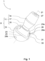
- the bottom portion 13 comprises a guidance through-hole 27 extending along a guidance through-hole central axis 21. As illustrated in Fig. 1 , the top portion 11 extends symmetrically about the guidance through-hole central axis 21.
- the bottom portion 13 includes a circumferential groove 25 in a plane extending orthogonally to the guidance through-hole central axis 21.
- Such circumferential groove 25 serves as a visual depth marker 25, 49 to help the surgeon determine the depth in which the bottom portion 13 of the surgical targeting device 1 shall be positioned in the trapezium bone.
- a distance between a plane comprising the circumferential groove 25 (or any other depth marker) and a plane comprising the end of the bottom portion 13 facing towards the trapezium bone may lie between 2 mm and 7 mm in all embodiments presented herein.
- the surgical targeting device 1 also comprises three auxiliary through-holes 29, only two of which are visible in the perspective view of Fig. 1 .
- the auxiliary through-holes 29 constitute surface irregularities in the otherwise uniform outer surface 23 of the bottom portion 13.
- Each auxiliary through-hole 29 extends through the bottom portion 13, but not through the top portion 11.
- the surgical targeting device 2 is placed in the trapezium bone at a desired location and orientation.
- the desired position and orientation may be checked using medical imaging methods.
- auxiliary attachment members 37 such as K-wires, with a diameter of, for example, 1.1 mm are inserted from a top to bottom direction of the surgical targeting device 2 through the respective auxiliary through-holes 29 and into the bone to temporarily fix the surgical targeting device 2 to the bone.
- a reamer with a central through-hole will be guided on this guidance K-wire 39 towards the bone at the desired location and orientation set by the guidance K-wire 39.
- the reamer is used to create a cavity required for an actual bone implant (here: a ball part of a ball and socket joint implant).
- the guidance K-wire is removed and the bone implant is introduced into the bone cavity created by the reamer.
- the surgical targeting device presented herein may have alternative shapes, exemplary embodiments of which are and discussed below.
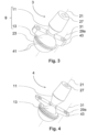
- Fig. 3 shows a perspective view of a surgical targeting device 3 similar to the first and second surgical targeting devices 1, 2 shown in Figs. 1 and 2 , respectively. Therefore, some of the features already discussed with regard to the first and second surgical targeting devices 1, 2 will not be repeated.
- the surgical targeting device 3 of Fig. 3 also comprises a monolithic body 9 with a top portion 11 and a bottom portion 13.
- the top portion 11 comprises two sections: a top truncated cone 15 and a bottom truncated cone 17.
- the top and bottom truncated cones 15, 17 are joined to each other by their respective larger surface ends and form a neck at the transition between the top portion 11 and the bottom portion 13.
- Fig. 6 shows a perspective view of another surgical targeting device 6 having a monolithic body 9 with a top portion 11 and a bottom portion 13.
- the top portion 11 comprises a truncated cone-shaped collar 45.
- This truncated cone-shaped collar 45 functions as a tool gripping structure provided for the engagement by a removal tool for removing the surgical targeting device 6 from the trapezium bone.
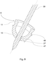
- Fig. 9 shows a perspective cross-section view of the surgical targeting device 6 of Fig. 6 with a guidance K-wire 39 inserted through and extending from its longitudinal through-hole 27 from the top portion 11 towards the bottom portion 13.
- Fig. 10 shows a perspective view of the surgical targeting device 8 of Fig. 8 with a guidance K-wire 39 inserted through and extending from its longitudinal through-hole 27 to be fixed in trapezium bone 55 (only schematically illustrated), and a tool 57 with an outer thread 59 corresponding to the internal thread 53 of the surgical targeting device 8 for removing the surgical targeting device 8 from the bone 55 along the fixed guidance K-wire 39.
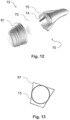
- Fig. 11 shows - for illustration purposes only - a lateral cross-section view of the surgical targeting device 2 of Fig. 2 inserted into a trapezium bone cup implant, i.e., a socket part 61of a ball and socket joint implant 70 as shown in Fig. 12 .
- the socket part 61 will be permanently inserted into and fixed to a recess formed in the trapezium bone by reaming along a guidance K-wire that has temporarily been fixed to the bone by means of the surgical targeting device 2 or any other of the surgical targeting devices presented herein.
- the ball and socket joint implant 70 shall be explained in the following with reference to Fig. 12 .
- the ball and socket joint implant 70 is divided into two parts that eventually form the actual artificial joint: a ball part 72 and the socket part 61. Both parts 61, 72 are permanently connected to the respective bones of the natural joint and pivotable relative to each other.
- the socket part 61 has a concave cup shape with a central opening. The outer surface of the socket part 61 engages with the trapezium bone to permanently remain in the bone while the opening with its concave inner surface remains accessible.
Landscapes
- Health & Medical Sciences (AREA)
- Orthopedic Medicine & Surgery (AREA)
- Life Sciences & Earth Sciences (AREA)
- Transplantation (AREA)
- Engineering & Computer Science (AREA)
- General Health & Medical Sciences (AREA)
- Biomedical Technology (AREA)
- Heart & Thoracic Surgery (AREA)
- Veterinary Medicine (AREA)
- Public Health (AREA)
- Animal Behavior & Ethology (AREA)
- Oral & Maxillofacial Surgery (AREA)
- Cardiology (AREA)
- Vascular Medicine (AREA)
- Surgery (AREA)
- Physical Education & Sports Medicine (AREA)
- Molecular Biology (AREA)
- Medical Informatics (AREA)
- Nuclear Medicine, Radiotherapy & Molecular Imaging (AREA)
- Dentistry (AREA)
- Prostheses (AREA)
- Surgical Instruments (AREA)
Claims (15)
- Chirurgische Zielvorrichtung (1-8) zur Unterstützung der Platzierung eines länglichen Führungselements (39) in einem Knochen (55), umfassend:einen unteren Abschnitt (13), der eine kuppelförmige konvexe Außenfläche (23) und ein Führungsdurchgangsloch (27) aufweist, das sich entlang einer Führungsdurchgangsloch-Mittelachse (21) zur Aufnahme des Führungselements (39) erstreckt; undeinen oberen Abschnitt (11), der dazu konfiguriert ist, von einem Werkzeug (57) gegriffen zu werden;dadurch gekennzeichnet, dassder untere Abschnitt (13) drei oder mehr Rippen (35) aufweist, die an der Außenfläche (23) in gleichen Umfangsabständen zueinander für einen vorübergehenden Eingriff mit dem Knochen (55) vorgesehen sind; und/oderdass der untere Abschnitt (13) drei oder mehr Dorne (47) für einen vorübergehenden Eingriff mit dem Knochen (55) aufweist, die von der Außenfläche (23) in eine Richtung nach unten entlang der Führungsdurchgangsloch-Mittelachse (21) vorstehen und in gleichen Umfangsabständen an der Außenfläche (23) in gleichem Abstand zur Führungsdurchgangsloch-Mittelachse (21) angeordnet sind.
- Chirurgische Zielvorrichtung (1-8) nach Anspruch 1, wobei
sich das Führungsdurchgangsloch (27) entlang der Führungsdurchgangsloch-Mittelachse (21) durch den unteren Abschnitt (13) und den oberen Abschnitt (11) erstreckt. - Chirurgische Zielvorrichtung (1-8) nach Anspruch 1 oder 2, wobei
der obere Abschnitt (11) einen Schaft (11) aufweist, der sich von dem unteren Abschnitt (13) aus erstreckt, wobei der Schaft (11) optional dazu konfiguriert ist, vorübergehend in einen Schaftzapfen eines Implantats oder eines Dummys davon eingeführt zu werden. - Chirurgische Zielvorrichtung (1-8) nach Anspruch 3, wobei
der Schaft (11) monolithisch mit dem unteren Abschnitt (13) ist oder mit diesem lösbar verbunden ist. - Chirurgische Zielvorrichtung (1-5) nach einem der Ansprüche 1 bis 4, wobeider untere Abschnitt (13) mindestens ein Hilfsdurchgangsloch (29) aufweist, das sich durch den unteren Abschnitt (13) entlang einer Hilfsdurchgangsloch-Mittelachse (31) erstreckt und von dem Führungsdurchgangsloch (27) beabstandet ist, wobei das mindestens eine Hilfsdurchgangsloch (29) dazu konfiguriert ist, ein Befestigungselement (37) aufzunehmen, sodass die Vorrichtung (1-5) vorübergehend mit dem Knochen (55) in Eingriff kommt, wobei optionaldie Hilfsdurchgangsloch-Mittelachse (31) sich schräg zur Führungsdurchgangsloch-Mittelachse (21) erstreckt.
- Chirurgische Zielvorrichtung (1, 2) nach Anspruch 5, wobei
die Führungsdurchgangsloch-Mittelachse (21) und die Hilfsdurchgangsloch-Mittelachse (31) sich nicht kreuzen. - Chirurgische Zielvorrichtung (1, 2) nach Anspruch 5 oder 6, wobei
sich das mindestens eine Hilfsdurchgangsloch (29) von einer oberen Öffnung (29a) zu einer unteren Öffnung (29b) in der Vorrichtung (1, 2) erstreckt, wobei die obere Öffnung (29a) weiter von der Führungsdurchgangsloch-Mittelachse (21) beabstandet ist als die untere Öffnung (29b). - Chirurgische Zielvorrichtung (3-5) nach einem der Ansprüche 5 bis 7, wobei
der untere Abschnitt (13) einen oder mehrere Flügel (43) aufweist, die seitlich von dem unteren Abschnitt (13) weg ragen und jeweils mindestens eines des mindestens einen Hilfsdurchgangslochs (29) aufweisen. - Chirurgische Zielvorrichtung (2, 6-8) nach einem der Ansprüche 1 bis 8, wobeider untere Abschnitt (13) eine visuelle Tiefenmarkierung (25, 41, 49) aufweist, die eine Ebene anzeigt, die sich orthogonal zu der Führungsdurchgangsloch-Mittelachse (21) erstreckt, wobei optionaldie visuelle Tiefenmarkierung (25, 41, 49) eine umlaufende Markierung, Rille (25) oder Kante (49) ist.
- Chirurgische Zielvorrichtung (1-8) nach einem der Ansprüche 1 bis 9, wobei
der obere Abschnitt (11) eine Werkzeuggreifstruktur (15, 17; 45) umfasst, die dazu konfiguriert ist, von dem Werkzeug (57) zum Entfernen der chirurgischen Zielvorrichtung (1-8) von dem Knochen (55) ergriffen zu werden. - Chirurgische Zielvorrichtung (1-6, 8) nach Anspruch 10, wobei
die Werkzeuggreifstruktur (15, 17; 45) einen Hals (17, 45) umfasst. - Chirurgische Zielvorrichtung (8) nach Anspruch 10 oder 11, wobei
die Werkzeuggreifstruktur (45) ein Gewinde (53) oder eine bajonettartige Schnittstelle (51) aufweist. - Chirurgische Zielvorrichtung (1-8) nach einem der Ansprüche 1 bis 12, wobei
die Führungsdurchgangsloch-Mittelachse (21) sich in einer Symmetrieebene der chirurgischen Zielvorrichtung (1-8) erstreckt. - Chirurgisches System, umfassend:die chirurgische Zielvorrichtung (1-8) nach einem der vorhergehenden Ansprüche; undein Pfannenteil (61) eines Kugelgelenkimplantats (70);wobei der untere Abschnitt (13) der chirurgischen Zielvorrichtung (1-8) in ein Volumen passt, das durch die äußeren Abmessungen des Pfannenteils (61) des Kugelgelenkimplantats (70) definiert ist, wobei optionaldie kuppelförmige konvexe Außenfläche (23) des unteren Abschnitts (13) der chirurgischen Vorrichtung (1-8) kugelförmig ist; undder Pfannenteil (61) des Kugelgelenkimplantats (70) eine konisch geformte Außenfläche aufweist.
- Chirurgisches System nach Anspruch 14, ferner umfassend:ein Kugelteil (72) des Kugelgelenkimplantats (70), wobei das Kugelteil (72) umfasst:einen Kopf (73),einen Schaft (74), der sich von dem Kopf (73) erstreckt, undeinen Schaftzapfen (75), der in der Lage ist, zumidnest einen Teil des Schafts (74) des Kugelteils (72) aufzunehmen;wobei der obere Abschnitt (11) der chirurgischen Zielvorrichtung (1-8) und der Abschnitt des Schafts (74) des Kugelteils (72), der von dem Schaft (75) aufgenommen werden kann, entsprechende Außenabmessungen haben, die in dem Schaftzapfen (75) aufgenommen werden können.
Priority Applications (1)
| Application Number | Priority Date | Filing Date | Title |
|---|---|---|---|
| EP21174302.6A EP3903699B1 (de) | 2019-09-17 | 2019-09-17 | Chirurgische zielvorrichtung |
Applications Claiming Priority (2)
| Application Number | Priority Date | Filing Date | Title |
|---|---|---|---|
| EP21174302.6A EP3903699B1 (de) | 2019-09-17 | 2019-09-17 | Chirurgische zielvorrichtung |
| EP19197676.0A EP3795098B1 (de) | 2019-09-17 | 2019-09-17 | Chirurgische zielvorrichtung |
Related Parent Applications (2)
| Application Number | Title | Priority Date | Filing Date |
|---|---|---|---|
| EP19197676.0A Division-Into EP3795098B1 (de) | 2019-09-17 | 2019-09-17 | Chirurgische zielvorrichtung |
| EP19197676.0A Division EP3795098B1 (de) | 2019-09-17 | 2019-09-17 | Chirurgische zielvorrichtung |
Publications (3)
| Publication Number | Publication Date |
|---|---|
| EP3903699A2 EP3903699A2 (de) | 2021-11-03 |
| EP3903699A3 EP3903699A3 (de) | 2022-01-19 |
| EP3903699B1 true EP3903699B1 (de) | 2024-07-10 |
Family
ID=67988895
Family Applications (2)
| Application Number | Title | Priority Date | Filing Date |
|---|---|---|---|
| EP21174302.6A Active EP3903699B1 (de) | 2019-09-17 | 2019-09-17 | Chirurgische zielvorrichtung |
| EP19197676.0A Active EP3795098B1 (de) | 2019-09-17 | 2019-09-17 | Chirurgische zielvorrichtung |
Family Applications After (1)
| Application Number | Title | Priority Date | Filing Date |
|---|---|---|---|
| EP19197676.0A Active EP3795098B1 (de) | 2019-09-17 | 2019-09-17 | Chirurgische zielvorrichtung |
Country Status (2)
| Country | Link |
|---|---|
| US (1) | US11707362B2 (de) |
| EP (2) | EP3903699B1 (de) |
Families Citing this family (2)
| Publication number | Priority date | Publication date | Assignee | Title |
|---|---|---|---|---|
| WO2022216790A1 (en) * | 2021-04-06 | 2022-10-13 | Arley Perez | Bone fixation devices, systems, kits, and methods |
| US20240390043A1 (en) * | 2023-05-22 | 2024-11-28 | Shahryar Ahmadi | System for the surgical treatment of fractures such as proximal humerus fractures and including a novel drill guide, optional intramedullary expandable bone anchor and reduction drill guide |
Family Cites Families (10)
| Publication number | Priority date | Publication date | Assignee | Title |
|---|---|---|---|---|
| US8454619B1 (en) * | 2008-12-10 | 2013-06-04 | William C. Head | Prosthetic socket alignment |
| WO2012021857A2 (en) * | 2010-08-13 | 2012-02-16 | Mason James Bettenga | Surgical guides |
| EP2632349B1 (de) * | 2010-10-29 | 2018-03-07 | The Cleveland Clinic Foundation | Hilfssystem zur befestigung eines serienimplantats an einem patientengewebe |
| US10456264B2 (en) * | 2014-01-24 | 2019-10-29 | Tornier, Inc. | Humeral implant anchor system |
| US9615839B2 (en) * | 2014-03-18 | 2017-04-11 | Howmedica Osteonics Corp. | Shape-fit glenoid reaming systems and methods |
| EP3210550B1 (de) * | 2016-01-27 | 2018-10-10 | Biedermann Technologies GmbH & Co. KG | Instrumentenführungsanordnung für eine knochenplatte und bausatz einer knochenplatte mit solch einer instrumentenführungsanordnung |
| CN105559951B (zh) * | 2016-03-01 | 2017-04-26 | 上海昕健医疗技术有限公司 | 个性化定制的髋臼导板 |
| CN109788960B (zh) * | 2016-08-15 | 2022-03-08 | 因奎创新有限责任公司 | 骨融合装置、系统和方法 |
| US10925658B2 (en) * | 2017-04-21 | 2021-02-23 | Zimmer, Inc. | Guide wire alignment |
| CN109820591B (zh) * | 2019-03-13 | 2024-07-09 | 华中科技大学同济医学院附属协和医院 | 一种基于骨盆微创手术的骨折复位导向固定器 |
-
2019
- 2019-09-17 EP EP21174302.6A patent/EP3903699B1/de active Active
- 2019-09-17 EP EP19197676.0A patent/EP3795098B1/de active Active
-
2020
- 2020-09-16 US US17/022,887 patent/US11707362B2/en active Active
Also Published As
| Publication number | Publication date |
|---|---|
| EP3795098B1 (de) | 2021-11-17 |
| EP3795098A1 (de) | 2021-03-24 |
| US11707362B2 (en) | 2023-07-25 |
| EP3903699A3 (de) | 2022-01-19 |
| EP3903699A2 (de) | 2021-11-03 |
| US20210077277A1 (en) | 2021-03-18 |
Similar Documents
| Publication | Publication Date | Title |
|---|---|---|
| EP3068317B1 (de) | Patientenspezifisches schulterinstrument | |
| US7828806B2 (en) | Accessory for implanting a hip endoprosthesis, and method for manipulating the same | |
| US9918743B2 (en) | Facet interference cage | |
| EP3025657A1 (de) | Knochenplattenanordnung mit führungsglied | |
| AU2020260530B2 (en) | Ball and cup impactors for implanting a hip prosthesis | |
| WO2013007785A1 (en) | Surgical instrument for the positioning of an alignment element | |
| US12137953B2 (en) | Humeral fixation plates | |
| US20150100060A1 (en) | Acetabular cup insertion instruments | |
| JP2012519555A (ja) | 大腿骨頚ガイドワイヤーの位置決め用のシステム、方法、及び装置 | |
| US11707362B2 (en) | Surgical targeting device | |
| EP2731512B1 (de) | Verfahren zur herstellung eines chirurgischen instruments zur positionierung eines ausrichtungselements | |
| EP3111897B1 (de) | Orthopädische einschlagvorrichtung | |
| US20180132867A1 (en) | System for orthopedic implantation preparation | |
| JP6208149B2 (ja) | インプラント固定部材ホルダー | |
| WO2013046172A1 (en) | An orthopaedic apparatus | |
| EP3920817B1 (de) | Vorrichtung zur fixation einer distalen radiusfraktur | |
| US20170360479A1 (en) | Conical end cap for intramedullary nail | |
| BR122022019662B1 (pt) | Conjunto de impactor de taça femoral, e, kit | |
| BR122022019659B1 (pt) | Conjunto de impactor de esfera acetabular, e, kit |
Legal Events
| Date | Code | Title | Description |
|---|---|---|---|
| PUAI | Public reference made under article 153(3) epc to a published international application that has entered the european phase |
Free format text: ORIGINAL CODE: 0009012 |
|
| STAA | Information on the status of an ep patent application or granted ep patent |
Free format text: STATUS: THE APPLICATION HAS BEEN PUBLISHED |
|
| AC | Divisional application: reference to earlier application |
Ref document number: 3795098 Country of ref document: EP Kind code of ref document: P |
|
| AK | Designated contracting states |
Kind code of ref document: A2 Designated state(s): AL AT BE BG CH CY CZ DE DK EE ES FI FR GB GR HR HU IE IS IT LI LT LU LV MC MK MT NL NO PL PT RO RS SE SI SK SM TR |
|
| PUAL | Search report despatched |
Free format text: ORIGINAL CODE: 0009013 |
|
| AK | Designated contracting states |
Kind code of ref document: A3 Designated state(s): AL AT BE BG CH CY CZ DE DK EE ES FI FR GB GR HR HU IE IS IT LI LT LU LV MC MK MT NL NO PL PT RO RS SE SI SK SM TR |
|
| RIC1 | Information provided on ipc code assigned before grant |
Ipc: A61F 2/42 20060101ALI20211213BHEP Ipc: A61B 17/17 20060101AFI20211213BHEP |
|
| STAA | Information on the status of an ep patent application or granted ep patent |
Free format text: STATUS: REQUEST FOR EXAMINATION WAS MADE |
|
| 17P | Request for examination filed |
Effective date: 20220406 |
|
| RBV | Designated contracting states (corrected) |
Designated state(s): AL AT BE BG CH CY CZ DE DK EE ES FI FR GB GR HR HU IE IS IT LI LT LU LV MC MK MT NL NO PL PT RO RS SE SI SK SM TR |
|
| STAA | Information on the status of an ep patent application or granted ep patent |
Free format text: STATUS: EXAMINATION IS IN PROGRESS |
|
| 17Q | First examination report despatched |
Effective date: 20230314 |
|
| GRAP | Despatch of communication of intention to grant a patent |
Free format text: ORIGINAL CODE: EPIDOSNIGR1 |
|
| STAA | Information on the status of an ep patent application or granted ep patent |
Free format text: STATUS: GRANT OF PATENT IS INTENDED |
|
| INTG | Intention to grant announced |
Effective date: 20240227 |
|
| GRAS | Grant fee paid |
Free format text: ORIGINAL CODE: EPIDOSNIGR3 |
|
| GRAA | (expected) grant |
Free format text: ORIGINAL CODE: 0009210 |
|
| STAA | Information on the status of an ep patent application or granted ep patent |
Free format text: STATUS: THE PATENT HAS BEEN GRANTED |
|
| P01 | Opt-out of the competence of the unified patent court (upc) registered |
Effective date: 20240528 |
|
| AC | Divisional application: reference to earlier application |
Ref document number: 3795098 Country of ref document: EP Kind code of ref document: P |
|
| AK | Designated contracting states |
Kind code of ref document: B1 Designated state(s): AL AT BE BG CH CY CZ DE DK EE ES FI FR GB GR HR HU IE IS IT LI LT LU LV MC MK MT NL NO PL PT RO RS SE SI SK SM TR |
|
| REG | Reference to a national code |
Ref country code: CH Ref legal event code: EP |
|
| REG | Reference to a national code |
Ref country code: DE Ref legal event code: R096 Ref document number: 602019055225 Country of ref document: DE |
|
| REG | Reference to a national code |
Ref country code: LT Ref legal event code: MG9D |
|
| REG | Reference to a national code |
Ref country code: NL Ref legal event code: MP Effective date: 20240710 |
|
| PG25 | Lapsed in a contracting state [announced via postgrant information from national office to epo] |
Ref country code: PT Free format text: LAPSE BECAUSE OF FAILURE TO SUBMIT A TRANSLATION OF THE DESCRIPTION OR TO PAY THE FEE WITHIN THE PRESCRIBED TIME-LIMIT Effective date: 20241111 |
|
| REG | Reference to a national code |
Ref country code: AT Ref legal event code: MK05 Ref document number: 1701316 Country of ref document: AT Kind code of ref document: T Effective date: 20240710 |
|
| PG25 | Lapsed in a contracting state [announced via postgrant information from national office to epo] |
Ref country code: NL Free format text: LAPSE BECAUSE OF FAILURE TO SUBMIT A TRANSLATION OF THE DESCRIPTION OR TO PAY THE FEE WITHIN THE PRESCRIBED TIME-LIMIT Effective date: 20240710 |
|
| PG25 | Lapsed in a contracting state [announced via postgrant information from national office to epo] |
Ref country code: PT Free format text: LAPSE BECAUSE OF FAILURE TO SUBMIT A TRANSLATION OF THE DESCRIPTION OR TO PAY THE FEE WITHIN THE PRESCRIBED TIME-LIMIT Effective date: 20241111 Ref country code: NL Free format text: LAPSE BECAUSE OF FAILURE TO SUBMIT A TRANSLATION OF THE DESCRIPTION OR TO PAY THE FEE WITHIN THE PRESCRIBED TIME-LIMIT Effective date: 20240710 |
|
| PG25 | Lapsed in a contracting state [announced via postgrant information from national office to epo] |
Ref country code: NO Free format text: LAPSE BECAUSE OF FAILURE TO SUBMIT A TRANSLATION OF THE DESCRIPTION OR TO PAY THE FEE WITHIN THE PRESCRIBED TIME-LIMIT Effective date: 20241010 |
|
| PG25 | Lapsed in a contracting state [announced via postgrant information from national office to epo] |
Ref country code: FI Free format text: LAPSE BECAUSE OF FAILURE TO SUBMIT A TRANSLATION OF THE DESCRIPTION OR TO PAY THE FEE WITHIN THE PRESCRIBED TIME-LIMIT Effective date: 20240710 Ref country code: PL Free format text: LAPSE BECAUSE OF FAILURE TO SUBMIT A TRANSLATION OF THE DESCRIPTION OR TO PAY THE FEE WITHIN THE PRESCRIBED TIME-LIMIT Effective date: 20240710 Ref country code: GR Free format text: LAPSE BECAUSE OF FAILURE TO SUBMIT A TRANSLATION OF THE DESCRIPTION OR TO PAY THE FEE WITHIN THE PRESCRIBED TIME-LIMIT Effective date: 20241011 |
|
| PG25 | Lapsed in a contracting state [announced via postgrant information from national office to epo] |
Ref country code: BG Free format text: LAPSE BECAUSE OF FAILURE TO SUBMIT A TRANSLATION OF THE DESCRIPTION OR TO PAY THE FEE WITHIN THE PRESCRIBED TIME-LIMIT Effective date: 20240710 |
|
| PG25 | Lapsed in a contracting state [announced via postgrant information from national office to epo] |
Ref country code: LV Free format text: LAPSE BECAUSE OF FAILURE TO SUBMIT A TRANSLATION OF THE DESCRIPTION OR TO PAY THE FEE WITHIN THE PRESCRIBED TIME-LIMIT Effective date: 20240710 |
|
| PG25 | Lapsed in a contracting state [announced via postgrant information from national office to epo] |
Ref country code: IS Free format text: LAPSE BECAUSE OF FAILURE TO SUBMIT A TRANSLATION OF THE DESCRIPTION OR TO PAY THE FEE WITHIN THE PRESCRIBED TIME-LIMIT Effective date: 20241110 Ref country code: AT Free format text: LAPSE BECAUSE OF FAILURE TO SUBMIT A TRANSLATION OF THE DESCRIPTION OR TO PAY THE FEE WITHIN THE PRESCRIBED TIME-LIMIT Effective date: 20240710 |
|
| PG25 | Lapsed in a contracting state [announced via postgrant information from national office to epo] |
Ref country code: HR Free format text: LAPSE BECAUSE OF FAILURE TO SUBMIT A TRANSLATION OF THE DESCRIPTION OR TO PAY THE FEE WITHIN THE PRESCRIBED TIME-LIMIT Effective date: 20240710 |
|
| PG25 | Lapsed in a contracting state [announced via postgrant information from national office to epo] |
Ref country code: ES Free format text: LAPSE BECAUSE OF FAILURE TO SUBMIT A TRANSLATION OF THE DESCRIPTION OR TO PAY THE FEE WITHIN THE PRESCRIBED TIME-LIMIT Effective date: 20240710 Ref country code: RS Free format text: LAPSE BECAUSE OF FAILURE TO SUBMIT A TRANSLATION OF THE DESCRIPTION OR TO PAY THE FEE WITHIN THE PRESCRIBED TIME-LIMIT Effective date: 20241010 |
|
| PG25 | Lapsed in a contracting state [announced via postgrant information from national office to epo] |
Ref country code: RS Free format text: LAPSE BECAUSE OF FAILURE TO SUBMIT A TRANSLATION OF THE DESCRIPTION OR TO PAY THE FEE WITHIN THE PRESCRIBED TIME-LIMIT Effective date: 20241010 Ref country code: PL Free format text: LAPSE BECAUSE OF FAILURE TO SUBMIT A TRANSLATION OF THE DESCRIPTION OR TO PAY THE FEE WITHIN THE PRESCRIBED TIME-LIMIT Effective date: 20240710 Ref country code: NO Free format text: LAPSE BECAUSE OF FAILURE TO SUBMIT A TRANSLATION OF THE DESCRIPTION OR TO PAY THE FEE WITHIN THE PRESCRIBED TIME-LIMIT Effective date: 20241010 Ref country code: LV Free format text: LAPSE BECAUSE OF FAILURE TO SUBMIT A TRANSLATION OF THE DESCRIPTION OR TO PAY THE FEE WITHIN THE PRESCRIBED TIME-LIMIT Effective date: 20240710 Ref country code: IS Free format text: LAPSE BECAUSE OF FAILURE TO SUBMIT A TRANSLATION OF THE DESCRIPTION OR TO PAY THE FEE WITHIN THE PRESCRIBED TIME-LIMIT Effective date: 20241110 Ref country code: HR Free format text: LAPSE BECAUSE OF FAILURE TO SUBMIT A TRANSLATION OF THE DESCRIPTION OR TO PAY THE FEE WITHIN THE PRESCRIBED TIME-LIMIT Effective date: 20240710 Ref country code: GR Free format text: LAPSE BECAUSE OF FAILURE TO SUBMIT A TRANSLATION OF THE DESCRIPTION OR TO PAY THE FEE WITHIN THE PRESCRIBED TIME-LIMIT Effective date: 20241011 Ref country code: FI Free format text: LAPSE BECAUSE OF FAILURE TO SUBMIT A TRANSLATION OF THE DESCRIPTION OR TO PAY THE FEE WITHIN THE PRESCRIBED TIME-LIMIT Effective date: 20240710 Ref country code: ES Free format text: LAPSE BECAUSE OF FAILURE TO SUBMIT A TRANSLATION OF THE DESCRIPTION OR TO PAY THE FEE WITHIN THE PRESCRIBED TIME-LIMIT Effective date: 20240710 Ref country code: BG Free format text: LAPSE BECAUSE OF FAILURE TO SUBMIT A TRANSLATION OF THE DESCRIPTION OR TO PAY THE FEE WITHIN THE PRESCRIBED TIME-LIMIT Effective date: 20240710 Ref country code: AT Free format text: LAPSE BECAUSE OF FAILURE TO SUBMIT A TRANSLATION OF THE DESCRIPTION OR TO PAY THE FEE WITHIN THE PRESCRIBED TIME-LIMIT Effective date: 20240710 |
|
| REG | Reference to a national code |
Ref country code: DE Ref legal event code: R097 Ref document number: 602019055225 Country of ref document: DE |
|
| PG25 | Lapsed in a contracting state [announced via postgrant information from national office to epo] |
Ref country code: RO Free format text: LAPSE BECAUSE OF FAILURE TO SUBMIT A TRANSLATION OF THE DESCRIPTION OR TO PAY THE FEE WITHIN THE PRESCRIBED TIME-LIMIT Effective date: 20240710 Ref country code: SM Free format text: LAPSE BECAUSE OF FAILURE TO SUBMIT A TRANSLATION OF THE DESCRIPTION OR TO PAY THE FEE WITHIN THE PRESCRIBED TIME-LIMIT Effective date: 20240710 Ref country code: DK Free format text: LAPSE BECAUSE OF FAILURE TO SUBMIT A TRANSLATION OF THE DESCRIPTION OR TO PAY THE FEE WITHIN THE PRESCRIBED TIME-LIMIT Effective date: 20240710 |
|
| PG25 | Lapsed in a contracting state [announced via postgrant information from national office to epo] |
Ref country code: EE Free format text: LAPSE BECAUSE OF FAILURE TO SUBMIT A TRANSLATION OF THE DESCRIPTION OR TO PAY THE FEE WITHIN THE PRESCRIBED TIME-LIMIT Effective date: 20240710 Ref country code: MC Free format text: LAPSE BECAUSE OF FAILURE TO SUBMIT A TRANSLATION OF THE DESCRIPTION OR TO PAY THE FEE WITHIN THE PRESCRIBED TIME-LIMIT Effective date: 20240710 |
|
| PG25 | Lapsed in a contracting state [announced via postgrant information from national office to epo] |
Ref country code: CZ Free format text: LAPSE BECAUSE OF FAILURE TO SUBMIT A TRANSLATION OF THE DESCRIPTION OR TO PAY THE FEE WITHIN THE PRESCRIBED TIME-LIMIT Effective date: 20240710 |
|
| PG25 | Lapsed in a contracting state [announced via postgrant information from national office to epo] |
Ref country code: SK Free format text: LAPSE BECAUSE OF FAILURE TO SUBMIT A TRANSLATION OF THE DESCRIPTION OR TO PAY THE FEE WITHIN THE PRESCRIBED TIME-LIMIT Effective date: 20240710 Ref country code: IT Free format text: LAPSE BECAUSE OF FAILURE TO SUBMIT A TRANSLATION OF THE DESCRIPTION OR TO PAY THE FEE WITHIN THE PRESCRIBED TIME-LIMIT Effective date: 20240710 |
|
| PLBE | No opposition filed within time limit |
Free format text: ORIGINAL CODE: 0009261 |
|
| STAA | Information on the status of an ep patent application or granted ep patent |
Free format text: STATUS: NO OPPOSITION FILED WITHIN TIME LIMIT |
|
| PG25 | Lapsed in a contracting state [announced via postgrant information from national office to epo] |
Ref country code: LU Free format text: LAPSE BECAUSE OF NON-PAYMENT OF DUE FEES Effective date: 20240917 |
|
| 26N | No opposition filed |
Effective date: 20250411 |
|
| REG | Reference to a national code |
Ref country code: BE Ref legal event code: MM Effective date: 20240930 |
|
| PG25 | Lapsed in a contracting state [announced via postgrant information from national office to epo] |
Ref country code: BE Free format text: LAPSE BECAUSE OF NON-PAYMENT OF DUE FEES Effective date: 20240930 |
|
| PG25 | Lapsed in a contracting state [announced via postgrant information from national office to epo] |
Ref country code: IE Free format text: LAPSE BECAUSE OF NON-PAYMENT OF DUE FEES Effective date: 20240917 |
|
| PG25 | Lapsed in a contracting state [announced via postgrant information from national office to epo] |
Ref country code: SE Free format text: LAPSE BECAUSE OF FAILURE TO SUBMIT A TRANSLATION OF THE DESCRIPTION OR TO PAY THE FEE WITHIN THE PRESCRIBED TIME-LIMIT Effective date: 20240710 |
|
| REG | Reference to a national code |
Ref country code: CH Ref legal event code: U11 Free format text: ST27 STATUS EVENT CODE: U-0-0-U10-U11 (AS PROVIDED BY THE NATIONAL OFFICE) Effective date: 20251001 |
|
| PGFP | Annual fee paid to national office [announced via postgrant information from national office to epo] |
Ref country code: DE Payment date: 20250702 Year of fee payment: 7 |
|
| PGFP | Annual fee paid to national office [announced via postgrant information from national office to epo] |
Ref country code: GB Payment date: 20250703 Year of fee payment: 7 |
|
| PGFP | Annual fee paid to national office [announced via postgrant information from national office to epo] |
Ref country code: FR Payment date: 20250708 Year of fee payment: 7 |
|
| PGFP | Annual fee paid to national office [announced via postgrant information from national office to epo] |
Ref country code: CH Payment date: 20251001 Year of fee payment: 7 |
|
| PG25 | Lapsed in a contracting state [announced via postgrant information from national office to epo] |
Ref country code: CY Free format text: LAPSE BECAUSE OF FAILURE TO SUBMIT A TRANSLATION OF THE DESCRIPTION OR TO PAY THE FEE WITHIN THE PRESCRIBED TIME-LIMIT; INVALID AB INITIO Effective date: 20190917 |
|
| PG25 | Lapsed in a contracting state [announced via postgrant information from national office to epo] |
Ref country code: HU Free format text: LAPSE BECAUSE OF FAILURE TO SUBMIT A TRANSLATION OF THE DESCRIPTION OR TO PAY THE FEE WITHIN THE PRESCRIBED TIME-LIMIT; INVALID AB INITIO Effective date: 20190917 |