EP3903745B1 - Système d'administration pour implant médical - Google Patents
Système d'administration pour implant médical Download PDFInfo
- Publication number
- EP3903745B1 EP3903745B1 EP19902238.5A EP19902238A EP3903745B1 EP 3903745 B1 EP3903745 B1 EP 3903745B1 EP 19902238 A EP19902238 A EP 19902238A EP 3903745 B1 EP3903745 B1 EP 3903745B1
- Authority
- EP
- European Patent Office
- Prior art keywords
- handle
- release
- rack
- delivery system
- medical implant
- Prior art date
- Legal status (The legal status is an assumption and is not a legal conclusion. Google has not performed a legal analysis and makes no representation as to the accuracy of the status listed.)
- Active
Links
Images



Classifications
-
- A—HUMAN NECESSITIES
- A61—MEDICAL OR VETERINARY SCIENCE; HYGIENE
- A61F—FILTERS IMPLANTABLE INTO BLOOD VESSELS; PROSTHESES; DEVICES PROVIDING PATENCY TO, OR PREVENTING COLLAPSING OF, TUBULAR STRUCTURES OF THE BODY, e.g. STENTS; ORTHOPAEDIC, NURSING OR CONTRACEPTIVE DEVICES; FOMENTATION; TREATMENT OR PROTECTION OF EYES OR EARS; BANDAGES, DRESSINGS OR ABSORBENT PADS; FIRST-AID KITS
- A61F2/00—Filters implantable into blood vessels; Prostheses, i.e. artificial substitutes or replacements for parts of the body; Appliances for connecting them with the body; Devices providing patency to, or preventing collapsing of, tubular structures of the body, e.g. stents
- A61F2/95—Instruments specially adapted for placement or removal of stents or stent-grafts
- A61F2/9517—Instruments specially adapted for placement or removal of stents or stent-grafts handle assemblies therefor
-
- A—HUMAN NECESSITIES
- A61—MEDICAL OR VETERINARY SCIENCE; HYGIENE
- A61F—FILTERS IMPLANTABLE INTO BLOOD VESSELS; PROSTHESES; DEVICES PROVIDING PATENCY TO, OR PREVENTING COLLAPSING OF, TUBULAR STRUCTURES OF THE BODY, e.g. STENTS; ORTHOPAEDIC, NURSING OR CONTRACEPTIVE DEVICES; FOMENTATION; TREATMENT OR PROTECTION OF EYES OR EARS; BANDAGES, DRESSINGS OR ABSORBENT PADS; FIRST-AID KITS
- A61F2/00—Filters implantable into blood vessels; Prostheses, i.e. artificial substitutes or replacements for parts of the body; Appliances for connecting them with the body; Devices providing patency to, or preventing collapsing of, tubular structures of the body, e.g. stents
- A61F2/95—Instruments specially adapted for placement or removal of stents or stent-grafts
- A61F2/962—Instruments specially adapted for placement or removal of stents or stent-grafts having an outer sleeve
- A61F2/966—Instruments specially adapted for placement or removal of stents or stent-grafts having an outer sleeve with relative longitudinal movement between outer sleeve and prosthesis, e.g. using a push rod
Definitions
- the present invention relates to the field of medical surgical instruments and, in particular, to a delivery system for a medical implant.
- cardiovascular disease is the number one killer of human beings.
- Medical implants including stents have been widely used in the treatment of various vascular diseases (e.g., aneurysms, dissections, thrombosis, stenosis, etc.). Most stents are implanted into patients' blood vessels through minimally invasive intervention. In general, such a procedure involves: loading a stent into a delivery system; advancing the delivery system to a target site through a vascular access established with a guidewire/catheter; releasing the stent by manipulating a release means in the delivery system; and withdrawing the delivery system, leaving the stent in the patient's body.
- the release of the stent must satisfy the following requirements. For a relatively long stent, it is necessary to minimize the time required for release and establish a blood flow as soon as possible in order to shorten a time period of ischemia of peripheral blood vessels or lower extremity blood vessels. Therefore, the release must be accomplished in a very short time over a long stroke length. Current delivery systems available on the market can rarely meet such performance requirements.
- US 2005/027305 A1 describes an integrated mechanical handle with quick slide mechanism.
- stents of various lengths can be released by rotating and/or axially retracting the release handle and thus driving distal movement of the rack. It allows a long release stroke length, and quick release can be achieved by axially retracting the release handle. In particular, quick and accurate release of long stents is made possible.
- the structural design of the proposed delivery system for a medical implant is simple but smart.
- the use of the honeycomb-like networks of handle reinforcing ribs not only results in greatly enhanced overall strength of the handle but can also achieve this at reasonable cost with a simple fabrication process.
- the delivery system is able to release long stents and provide an additional option for clinical physicians.
- distal is intended to refer to an end relatively located away from a target diseased site in a patient (where a stent is to be implanted) during a surgical procedure, while the term “proximal” is intended to refer to an end relatively close to the diseased site (the targeted stent implantation site).
- Embodiments disclosed herein relate to delivery system for the medical implants capable of releasing stents of various lengths by a rotating operation and/or an axially retracting operation. They allow a relative long release stroke length, and quick release can be achieved by axially retracting a release handle. In particular, quick and accurate release of long stents is made possible.
- Fig. 1 schematically illustrates the structure of a delivery system for a medical implant according to an embodiment of the present invention.
- the delivery system for the medical implant includes a handle housing 11, a release handle 101, a handle holder 102 and a rack 20.
- the handle housing 11 is a hollow tubular member defining a slot running along an axial direction of the hollow tubular member, and the rack 20 is received within the handle housing 11 in an orientation along the axial direction so as to be with at least some of the rack 20's teeth protruding out of the slot.
- the handle holder 102 is fixedly disposed over the handle housing 11, and the release handle 101 is disposed over the handle housing 11 into engagement with the teeth so that when the release handle 101 is rotated or axially retracted, the release handle 101 will drive the rack to move distally. When rotated, the release handle 101 engages against the handle holder 102 without axial movement relative thereto.
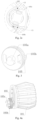
- Fig. 2a schematically illustrates the release handle 101 assembled with the handle holder 102 according to this embodiment.
- Fig. 2b is a schematic cross-sectional view taken along AA in Fig. 2a according to this embodiment.
- Fig. 2c is a schematic enlarged view of a portion of Fig. 2b according to this embodiment.
- Fig. 3 is a schematic illustration of a release switch according to an embodiment of the present invention.
- a release switch 105 for limiting axial movement and circumferential rotation of the release handle 101 is disposed between the release handle 101 and the handle holder 102. This can prevent operational errors of the operator.
- the release switch 105 may be in the form of, for example, a rotary disc, the release switch 105 is provided with a cam 105a at the distal end and a rotation stopper 105b at the proximal end, the rotation stopper 105b axially projecting from a location at a circumferential peripheral edge.
- a number of bridging legs 105c may be spaced from one another along the circumference of a central circumferential portion of the release switch 105.
- the handle holder 102 may define a first gap 102a for receiving the release switch 105 on a distal circumference.
- the release switch 105 may fit in the first gap 102a so that axes of the release switch 105 and the handle holder 102 are parallel to each other.
- the handle holder 102 may be provided, around the first gap 102a, with a ring-like support plate 102b that is matched with the release switch 105.
- the ring-like support plate 102b may be provided at a plane that is perpendicular to the aforementioned axial direction.
- the bridging legs 105c on the release switch 105 may be engaged with the ring-like support plate 102b to enable stable and steady rotation of the release switch 105.
- An outer peripheral edge of the ring-like support plate 102b may be situated within a sector defined by an arc along which the rotation stopper 105b is moveable with the release switch 105.
- the outer peripheral edge of the ring-like support plate 102b may not interfere with the rotation of the rotation stopper 105b.
- the outer peripheral edge of the ring-like support plate 102b may meet an inner wall of the handle holder 102 at a first notch C1 and a second notch C2.
- the rotation stopper 105b will come into abutment against the wall at the first notch C1 or second notch C2, thus stopping the release switch and disallowing its further movement.
- a maximum permissible angle of rotation for the release switch defined by the first and second notches C1 and C2 may be 180° or less. In this way, the release switch 105 may be limited to rotation within an angle that is smaller than or equal to 180°.
- the ring-like handle holder 102 may be fixedly disposed over the handle housing 11 such that an axial second gap 102c in the handle holder 102 is aligned with the slot in the handle housing 11.
- the second gap 102c may radially extend through the handle holder 102 so that when the rack 20 moves in the handle housing 11 along the slot, its teeth protruding out of the slot can smoothly pass through the second gap in the handle holder 102.
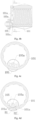
- Fig. 4a shows a schematic three-dimensional view of the release handle 101 assembled with the release switch 105 according to this embodiment.
- Fig. 4b is a schematic cross-sectional view of the release handle 101 assembled with the release switch 105 according to this embodiment.
- Fig. 4c is a schematic cross-sectional view of the release handle 101 of Fig. 4b in a released configuration taken along BB according to this embodiment.
- Fig. 4d is a schematic cross-sectional view of the release handle 101 of Fig. 4b in a locked configuration taken along BB according to this embodiment.
- Fig. 4e is a schematic enlarged view of a portion of Fig. 4d according to this embodiment.
- a number of limiting grooves 101a may be evenly provided along an inner circumference at a proximal end of the release handle 101, which are each complementary in shape with the cam 105a on the release switch 105 and contiguous with one another side by side.
- Each of the limiting grooves 101a has circumferential limiting protrusions D at its circumferentially opposing sides, as shown in Fig. 4d .
- the release handle 101 is also circumferentially limited (i.e., it cannot rotate anymore) because the cam 105a blocks movement of the circumferential limiting protrusions D of the notch with which it engages.
- the release handle 101 is unlocked (released) both axially and circumferentially. Therefore, locking (axial and circumferential limiting) and release of the release handle 101 can be accomplishing by engaging the cam 105a with one of the limiting grooves 101a and disengaging it from the limiting groove 101a.
- the cam 105a may define a unilateral limiting protrusion B2, and each limiting groove 101a may define, at a location near one of the circumferential limiting protrusions D, a third notch B1 that is engageable with the unilateral limiting protrusion B2.
- the release switch 105 can exert a clockwise turning force, and with combined reference to Fig. 2c , upon the rotation stopper 105b on the opposing side coming into engagement with the first limiting notch C1, further clockwise rotational movement of the release switch 105 is limited.
- the release switch 105 may be alternatively designed to exert a counterclockwise turning force in a similar way. Therefore, the rotation stopper 105b on the opposite side of the release switch 105 can only move along the arc between the first and second notches C1, C2, permitting the release switch 105 to rotate within an angle (angular stroke length) of 180° or less.
- This design can solve the problem with the current practice that although the release switch 105 can achieve a target unlocking (releasing) position, for example, a clockwise 60° turn, the operator like a physician would be unaware of this, and if he/she chooses the opposite direction, then the unlocking (releasing) will now require a 300° turn.
- the release handle 101 can be unlocked (released) always by turning the release switch 105 in one direction by an angle that is smaller than or equal to 180°.
- the shortening of the required angular stroke length can avoid unnecessary operational effort to be paid by, for example, the physician, and save his/her previous time.
- Fig. 5 shows a schematic diagram of an upper handle shell 103 according to this embodiment.
- Fig. 6a is a schematic diagram of a lower handle shell employing scattered reinforcing ribs 604b according to an embodiment of the present invention.
- Fig. 6b is a schematic diagram of a lower handle shell employing metal support bars 704b according to another embodiment of the present invention.
- Fig. 6c is a schematic diagram of a lower handle shell employing a honeycomb-like network of reinforcing ribs 104b according to yet another embodiment of the present invention.
- the handle housing 11 may include the upper and lower handle shells.
- the handle In order to adapt to a very long release stroke length, the handle itself needs to be designed with a total length of, for example, 340-350 mm. This may lead to the following two challenges for using polymer injection molded parts as the components.
- One of the challenges is that the parts are prone to warpage during injection molding.
- the other challenge is that the handle assembled from such parts tends to deform under significant stress or exhibit poor bending or torsion resistance.
- Various attempts were made to resolve these difficulties. Since the upper and lower handle shells are structured identically, only the lower handle shell is detailed below as an example. As shown in Fig.
- the first attempt used a reinforcing plate 604a and scattered internal reinforcing ribs 604b.
- the physical prototype was found to be with limited torsion resistance.
- the later second attempt used a reinforcing plate 704a and metal support bars 704b.
- the metal support bars 704b were added during injection molding of the part for the lower handle shell 704, and this was found to be very difficult and costly.
- the third attempt used expensive glass fiber reinforced injection molding pellets.
- two upper handle shell reinforcing plates 103a are arranged in a symmetrical configuration along the axial direction perpendicular to a reference plane.
- the reference plane is defined as a plane that passes through the lowest point of the lower handle shell 104 (in an orientation with the opening of this semi-tubular structure facing upward) and is tangent to the lower handle shell 104.
- the upper handle shell reinforcing plates 103a may extend axially from one end of the upper handle shell 103 to the other.
- the upper handle shell reinforcing ribs 103b there are also arranged upper handle shell reinforcing ribs 103b, the upper handle shell reinforcing plates 103a are attached to the upper handle shell reinforcing ribs 103b.
- the upper handle shell reinforcing ribs 103b may make up a honeycomb-like network.
- two lower handle shell reinforcing plates 104a are arranged in a symmetrical configuration along the axial direction perpendicular to the reference plane.
- the lower handle shell reinforcing plates 104a may extend axially from one end of the lower handle shell 104 to the other.
- the lower handle shell reinforcing plates 104a are attached to the lower handle shell reinforcing ribs 104b.
- the lower handle shell reinforcing ribs 104b may make up a honeycomb-like network.
- honeycomb-like networks of reinforcing ribs in the upper and lower handle shells 103, 104 is sensible because they can be easily injection-molded at a reasonable expense while imparting significantly improved axial stiffness to the upper and lower handle shells 103, 104, which ensures that the handle components will not bend or twist when heavily resisted during a release process.
- Fig. 7 schematically illustrates the lower handle shell 104 assembled with the rack 20 according to this embodiment.
- Fig. 8 is a schematic enlarged view of a portion of Fig. 7 according to this embodiment.
- the handle housing 11 includes the upper and lower handle shells 103, 104 detachably attached to each other.
- the upper and lower handle shells 103, 104 are semi-tubular members.
- the reference plane is defined as a plane that passes through the lowest point of the lower handle shell 104 (in an orientation with the opening of this semi-tubular structure facing upward) and is tangent to the lower handle shell 104.
- the axial direction of the handle housing 11 is defined as an X-direction, a direction that is within a plane parallel to the reference plane and perpendicular to the X-direction as a Y-direction, and a direction perpendicular to the reference plane as a Z-direction.
- Surfaces A of the upper and lower handle shells 103, 104 where they are put into contact with each other may be parallel to the reference plane.
- the teeth 20a of the rack 20 may be arranged side by side along the axial direction and some of them protrude out of the aforesaid slot.
- the rack 20 may have a rack internal cavity 20b extending through the rack axially and two rack slideways 20c, which are arranged in symmetry with respect to the axial (X-) direction and each assume an L-shaped radial cross-section.
- Each of the L-shaped rack slideways 20c may be made up of an arm oriented in the Y-direction and another arm oriented in the Z-direction.
- a number of rack reinforcing ribs 20d may be provided on the rack 20, which are arranged along the axial direction side by side with spaces therebetween, and the plurality of rack reinforcing ribs 20d have coplanar end faces 20e, the plane on which the end faces 20e of the rack reinforcing ribs are located is parallel to the reference plane.
- the rack slideways 20c may fit with the lower handle shell reinforcing plates 104a. Specifically, a portion of the rack 20 between the symmetrical rack slideways 20c may fit in a space between the symmetrical lower handle shell reinforcing plates 104a, with surfaces of the rack slideways 20c perpendicular to the reference plane fitting against surfaces of the lower handle shell reinforcing plates 104a perpendicular to the reference plane. This limits the rack 20 in the Y-direction.
- surfaces of the rack slideways 20c parallel to the reference plane may fit against surfaces of the lower handle shell reinforcing plates 104a parallel to the reference plane, and the end faces 20e of the rack reinforcing ribs may abut against the upper handle shell reinforcing plates 103a. This further limits the rack 20 in the Z-direction.
- the rack slideways 20c, the lower handle shell reinforcing plates 104a and the upper handle shell reinforcing plate 103a may together provide a release path in the handle assembly of the delivery system for the medical implant.
- the lower handle shell reinforcing plates 104a may axially extend from one to the other end of the lower handle shell 104, and the lower handle shell reinforcing plates 104a may be integrally attached to the lower handle shell reinforcing ribs 104b, and the upper handle shell reinforcing plates 103a may axially extend from one to the other end of the upper handle shell 103, and the upper handle shell reinforcing plates 103a may be integrally attached to the upper handle shell reinforcing ribs 103b.
- the lower and upper handle shell reinforcing plates 104a, 103a function both to make contribution to the release path and to strengthen the corresponding lower and upper handle shells 104, 103.
- the rack slideways 20c also strengthen the rack 20 while forming part of the release path.
- all the lower handle shell reinforcing plates 104a, the upper handle shell reinforcing plates 103a and the rack slideways 20c are bifunctional members that participate in the establishment of the release path and increase the strength of the corresponding components.
- Fig. 9 is a schematic cross-sectional view of the handle housing according to this embodiment.
- the handle housing 11 may include a tip section 11b, a first shaft section 11c and a second shaft section 11d.
- the tip section 11b, the first shaft section 11c and the second shaft section 11d are connected in series in the axially direction of the handle housing 11.
- the handle holder 102 may be fixedly disposed around the junction of the first and second shaft sections 11c, 11d.
- a diameter of the first shaft section 11c is greater than a diameter of the second shaft section 11d.
- the diameter of the first shaft section 11c may be equal to or smaller than that of the second shaft section 11d.
- first and second shaft sections 11c, 11d defines a step 11a at their junction so that the handle holder 102 is fixedly disposed around the step 11a.
- the junction of the first and second shaft sections 11c, 11d may be otherwise structured.
- the tip section 11b may resemble a tip portion of a pen.
- Each of the first and second shaft sections 11c, 11d may be a hollow tubular section defining an axially extending slot. The interiors of the first and second shaft sections 11c, 11d may communicate with each other.
- Fig. 10 is a schematic cross-sectional view of a portion of the delivery system for the medical implant according to this embodiment.
- Fig. 11 is a schematic cross-sectional view of a portion containing a stent according to this embodiment.
- the delivery system for the medical implant may further include an outer sheath 304.
- the handle housing 11 is a tubular member defining a slot running along an axial direction of the tubular member.
- the rack 20 is so received in the handle housing 11 that at least some teeth of the rack 20 protrude out of the slot.
- the handle holder 102 is fixedly disposed over the handle housing 11, and the release handle 101 is disposed over the handle housing 11 so as to engage the teeth.
- the rack will distally move in response to the release handle 101 being rotated or axially pulled.
- the release handle 101 engages with the handle holder 102 without any axial movement relative thereto.
- a distal end of the outer sheath 304 may be connected to a proximal end of the rack 20.
- the delivery system for the medical implant may further include an inner tube 301.
- the outer sheath 304 may be disposed over the inner tube 301 and thus define an accommodating space with the inner tube 301.
- a stent 303 may be received in a proximal portion of the accommodating space, and the stent 303 is generally tubular. The stent may be uniformly crimped and loaded in the cavity between the inner tube 301 and the outer sheath 304.
- the proximal end of the rack 20 may be connected to the distal end of the outer sheath 304 within the tip section 11b along the axial direction.
- an outer sheath connecting member 305 may be fixed to the distal end of the outer sheath 304
- a rack connecting member 306 may be arranged at the proximal end of the rack 20 with the aid of a sealing ring 307.
- the rack 20 may be fixedly connected to the outer sheath 304 by means of a threaded or snap connection between the rack connecting member 306 and the outer sheath connecting member 305.
- each of the outer sheath connecting member 305 and the rack connecting member 306 may define an axial through hole through which the inner tube 301 can be inserted.
- the rack internal cavity 20b of the rack 20 also allows the inner tube 301 to be axially inserted therethrough.
- Fig. 12 is a schematic cross-sectional view of the delivery system for the medical implant according to this embodiment in an initial configuration.
- Fig. 13 is a schematic cross-sectional view of the delivery system for the medical implant according to this embodiment that has experienced a rotational release process.
- Fig. 14 is a schematic cross-sectional view of the delivery system for the medical implant according to this embodiment in a configuration with a maximum release stroke length being reached. As shown in Figs. 12 to 14 , the delivery system for the medical implant according to this embodiment allows a maximum release stroke length of up to 280-300 mm, making it suitable for the release of stents for treating various vascular diseases, in particular those with a long diseased length or a complicated geometrical structure.
- the delivery system for the medical implant according to this embodiment can release a stent in three distinct ways.
- the release handle 101 engages with the handle holder 102, with the release switch 105 limiting the release handle 101 axially and circumferential and with the rack 20 being distally aligned with the release handle 101.
- release can be achieved simply by rotating the release handle 101.
- the release handle 101 may be turned in an axially stationary way (i.e., with the release handle 101 engaging with the handle holder 102 and no axial movement).
- the release handle 101 transmits a driving force by means of the rack 20 that it engages, causing the outer sheath 304 to move with the rack 20 distally in the axial direction until the stent 303 is (exposed and) released.
- the release may also be accomplished simply by axially retracting the release handle 101.
- the stent 303 being a long one requiring quick release
- the release handle 101 after the release handle 101 is unlocked by turning the release switch 105 in the initial configuration, it may be directly gripped and quickly pulled distally.
- the rack 20 moves linearly and distally in synchronization with the release handle 101 along the axial direction, achieving quick release of the stent 303.
- the stent may be also released by both rotating and axially retracting the release handle 101.
- the stent may be turned in an axially stationary way (i.e., with the release handle 101 engaging with the handle holder 102 and no axial movement) until the rack 20 moves into proximal alignment with the release handle 101, as shown in Fig. 13 .
- the release handle 101 may be then axially retracted distally, causing the rack 20 and hence the outer sheath 304 to move linearly and distally in synchronization with the release handle 101 in the axial direction, until the stent is released.
- a maximum release stroke length will be reached when the proximal ends of the rack 20 and the release handle 101 are both aligned with a distal end of the handle housing 11.
- the maximum release stroke length may be, for example, 280-300 mm. It will be appreciated that the release stroke length is the axial distance travelled by the rack, i.e., the distance the outer sheath axially moves with the rack.
- the axes of the handle housing 11, the outer sheath 304 and the inner tube 301 may be parallel to one another.
- the axes of the handle housing 11, the outer sheath 304 and the inner tube 301 coincide with one another.
- the inner tube 301 may be axially inserted through the handle housing 11.
- the inner tube 301 may be inserted sequentially through the through hole of the outer sheath connecting member 305, the through hole of the rack connecting member 306 and the rack internal cavity 20b of the rack 20 within the handle housing 11 and fixed to a distal end of the upper handle shell 103 by a protective tube 402.
- a handle end cover 106 may be fixed to a distal end of the handle housing 11.
- the inner tube 301 may axially extend so as to protrude out of the handle end cover 106 distally.
- An inner tube trailing end connecting member 401 may be detachably connected to a distal end of the protective tube 402, for example, by a threaded or tapered fit.
- the inner tube trailing end connecting member 401 may be detached to expand the release stroke length and allow the rack to further move outside the handle housing 11 until the proximal end of the rack reaches the distal end of the handle housing.
- the protective tube 402 may be disposed over the inner tube 301 and the proximal end of the protective tube 402 may be connected to a spring 302 within the tip section 11b. In this way, the inner tube 301, the spring 302, the protective tube 402 and the handle housing 11 are connected together.
- the inner tube 301 may be elongate, the portion of the inner tube 301 inside the handle housing 11 is supported and protected by the protective tube 402 and the portion of the inner tube 301 outside the handle housing 11 is supported and protected by the spring 302.
- the inner tube 301 may further have an axial extension proximally extending outside the handle housing 11.
- the stent 303 may be crimped over a proximal portion of the extension, and the spring 302 may be disposed over a distal portion of the extension that is not encompassed by the stent 303.
- a distal portion of the spring 302 may be received within the tip section 11b, and the axially extending outer sheath 304 may be disposed over both the stent 303 and the spring 302.
- the outer sheath 304 may be proximally aligned with the inner tube 301 and distally fixed to the outer sheath connecting member 305.
- the outer sheath 304 may be provided to protect the stent 303 and configured to be able to move distally when driven by the rack 20. Since the inner tube 301 is fixed in the handle housing 11 and the stent 303 is crimped on the inner tube 301, as a result of the distal movement of the outer sheath 304 with the rack 20, the stent 303 can be exposed and released. A clearance between the outer sheath 304 and the inner tube 301 may accommodate stents 303 for treating various vascular diseases.
- the outer sheath 304 may be relatively long, and the inner tube 301 may be relatively thin.
- the spring 302 may be disposed in a distal portion of the clearance between the outer sheath 304 and the inner tube 301 that does not encompass the stent 303. This makes the structure within the outer sheath 304 more stable and more compliant.
- a liquid supply tube 51 and a one-way valve 52 may be provided at a proximal end of the slot in the handle housing 11.
- the liquid supply tube 51 may be used to evacuate air from the delivery system for the medical implant by introducing physiological saline, and the one-way valve 52 may be configured to control the physiological saline to flow in only one direction.
- stents of various lengths can be released by rotating and/or axially retracting the release handle and thus driving distal movement of the rack.
- This system allows a long release stroke length, and quick release can be achieved by axially retracting the release handle. In particular, quick and accurate release of long stents is made possible.
- spatially relative terms such as “under”, “below”, “lower”, “upper” and the like, may be used for ease of description to describe one element or feature's relationship to another element(s) or feature(s) as illustrated in the figures.
- the spatially relative terms are intended to encompass different orientations of the device in use or operation in addition to the orientation depicted in the figures.
- the device may be otherwise oriented, for example, rotated 90 degrees or at other orientations, and the spatially relative descriptors used herein interpreted accordingly.
Landscapes
- Health & Medical Sciences (AREA)
- Engineering & Computer Science (AREA)
- Biomedical Technology (AREA)
- Cardiology (AREA)
- Oral & Maxillofacial Surgery (AREA)
- Transplantation (AREA)
- Heart & Thoracic Surgery (AREA)
- Vascular Medicine (AREA)
- Life Sciences & Earth Sciences (AREA)
- Animal Behavior & Ethology (AREA)
- General Health & Medical Sciences (AREA)
- Public Health (AREA)
- Veterinary Medicine (AREA)
- Prostheses (AREA)
- Media Introduction/Drainage Providing Device (AREA)
Claims (14)
- Système d'administration pour un implant médical, comprenant une coque de poignée (11), une poignée de libération (101), un support de poignée (102) et une crémaillère (20), la coque de poignée (11) mise en oeuvre sous la forme d'un élément tubulaire creux définissant une fente s'étendant le long d'une direction axiale de la coque de poignée (11), la crémaillère (20) reçue à l'intérieur de la coque de poignée (11) dans une orientation le long de la direction axiale de la coque de poignée (11), au moins certaines des dents de la crémaillère (20) faisant saillie hors de la fente, le support de poignée (102) disposé de manière fixe sur la coque de poignée (11), la poignée de libération (101) disposée sur la coque de poignée (11) en prise avec les dents de sorte que la crémaillère (20) se déplace de manière distale en conséquence d'une rotation ou d'une rétraction axiale de la poignée de libération (101), dans lequel lorsque la poignée de libération (101) est tournée, la poignée de libération (101) se met en prise avec le support de poignée (102) et reste stationnaire axialement par rapport au support de poignée (102),
caractérisé en ce que :un commutateur de libération (105) destiné à limiter le mouvement axial et la rotation circonférentielle de la poignée de libération (101) est agencé entre la poignée de libération (101) et le support de poignée (102),le commutateur de libération (105) a une extrémité distale pourvue d'une came (105a), et une surface interne d'une extrémité proximale de la poignée de libération (101) pourvue d'une pluralité de rainures de limitation (101a) agencées circonférentiellement par rapport à la poignée de libération (101), chaque rainure de limitation (101a) pouvant être mise en prise avec la came (105a) et ayant des saillies de limitation circonférentielles sur les deux extrémités le long d'une direction circonférentielle. - Système d'administration pour un implant médical selon la revendication 1, dans lequel le support de poignée (102) a une extrémité distale pourvue d'un premier espace, le commutateur de libération (105) partiellement encastré dans le premier espace et un axe du commutateur de libération (105) étant parallèle à un axe de la coque de poignée (11).
- Système d'administration pour un implant médical selon la revendication 2, dans lequel le support de poignée (102) est pourvu d'une plaque de support en forme d'anneau (102b) adaptée au commutateur de libération (105), la plaque de support en forme d'anneau (102b) ayant un axe parallèle à l'axe de la coque de poignée (11), et dans lequel le commutateur de libération (105) a une extrémité proximale pourvue d'au moins deux pattes de pontage (105c), chacune d'entre elles venant en prise avec une surface interne de la plaque de support en forme d'anneau (102b).
- Système d'administration pour un implant médical selon la revendication 3, dans lequel une surface externe de la plaque de support en forme d'anneau (102b) rencontre une surface interne du support de poignée (102) au niveau d'une première encoche et d'une seconde encoche, dans lequel l'extrémité proximale du commutateur de libération (105) est pourvue d'une butée de rotation (105b), et dans lequel, lorsque l'interrupteur de libération (105) est tourné dans le sens des aiguilles d'une montre ou dans le sens inverse, la butée de rotation (105b) est tournée vers la première encoche ou la seconde encoche, la butée de rotation (105b) est en prise avec la première encoche ou la seconde encoche, définissant ainsi un angle de rotation maximal admissible pour le commutateur de libération (105).
- Système d'administration pour un implant médical selon la revendication 4, dans lequel l'angle de rotation maximal admissible pour le commutateur de libération (105) est inférieur ou égal à 180°.
- Système d'administration pour un implant médical selon la revendication 1, dans lequel la came (105a) est pourvue d'une saillie de limitation unilatérale, chacune de la pluralité de rainures de limitation (101a) étant pourvue d'une troisième encoche pouvant être mise en prise avec la saillie de limitation unilatérale, la saillie de limitation unilatérale et la troisième encoche coopèrent pour permettre une rotation unidirectionnelle pour le commutateur de libération (105).
- Système d'administration pour un implant médical selon la revendication 1, dans lequel la coque de poignée (11) comprend une coque de poignée supérieure (103) et une coque de poignée inférieure (104, 604, 704) qui sont connectées de manière détachable, et
dans lequel la coque de poignée supérieure (103) est pourvue à l'intérieur d'une plaque de renforcement de coque de poignée supérieure (103a) le long d'une direction axiale de la coque de poignée supérieure (103), dans lequel la coque de poignée inférieure (104, 604, 704) est pourvue à l'intérieur d'une plaque de renforcement de coque de poignée inférieure (104a, 604a, 704a) le long d'une direction axiale de la coque de poignée inférieure (104, 604, 704), dans lequel, sur un côté de la crémaillère (20) proche de la coque de poignée inférieure (104, 604, 704), est prévue une glissière de crémaillère (20c) capable de s'adapter à la plaque de renforcement de coque de poignée inférieure (104a, 604a, 704a), la glissière de crémaillère (20c) s'étendant le long de la direction axiale de la coque de poignée (11), et dans lequel la crémaillère (20) bute contre la plaque de renforcement de coque de poignée supérieure (103a) sur un côté de celle-ci proche de la coque de poignée supérieure (103). - Système d'administration pour un implant médical selon la revendication 7, dans lequel une pluralité de nervures de renforcement de crémaillère (20d) sont prévues sur la crémaillère (20) à des intervalles le long d'une direction axiale de la crémaillère (20).
- Système d'administration pour un implant médical selon la revendication 7, dans lequel la coque de poignée supérieure (103) est en outre pourvue à l'intérieur d'un réseau de type nid d'abeille de nervures de renforcement de la coque de poignée supérieure (103b), et la coque de poignée inférieure (104, 604, 704) est en outre pourvue à l'intérieur d'un réseau de type nid d'abeille de nervures de renforcement de la coque de poignée inférieure (104b), et
dans lequel les nervures de renforcement de la coque de poignée supérieure (103b) sont fixées à la plaque de renforcement de la coque de poignée supérieure (103a), et les nervures de renforcement de la coque de poignée inférieure (104b) sont fixées à la plaque de renforcement de la coque de poignée inférieure (104a, 604a, 704a). - Système d'administration pour un implant médical selon l'une quelconque des revendications 1 à 9, dans lequel la coque de poignée (11) comprend une section de pointe (11b), une première section de tige (11c) et une seconde section de tige (11d), qui sont connectées en série dans la direction axiale, dans lequel le support de poignée (102) est disposé de manière fixe autour d'une jonction des première et seconde sections de tige.
- Système d'administration pour un implant médical selon la revendication 10, dans lequel un diamètre de la première section de tige (11c) est supérieur à un diamètre de la seconde section de tige (11d), un épaulement (11a) prévu à la jonction des première et seconde sections de tige, et le support de poignée (102) disposé de manière fixe autour de l'épaulement (11a), et/ou
dans lequel la section de pointe (11b) ressemble à une partie de pointe d'un stylo, et chacune des première et seconde sections de tige (11c, 11d) est un élément tubulaire creux pourvu de la fente dans la direction axiale. - Système d'administration pour un implant médical selon l'une quelconque des revendications 1 à 9, dans lequel la crémaillère (20) définit une cavité interne de crémaillère (20b) s'étendant à travers la crémaillère (20) le long de la direction axiale.
- Système d'administration pour un implant médical selon la revendication 2, dans lequel le support de poignée (102) définit un second espace correspondant à la fente le long de la direction axiale.
- Système d'administration pour un implant médical selon la revendication 1, comprenant en outre une gaine externe (304) avec une extrémité distale connectée à une extrémité proximale de la crémaillère (20), dans lequel la rotation ou la rétraction axiale de la poignée de libération (101) provoque un mouvement distal de la crémaillère (20) et donc un mouvement distal de la gaine externe (304) avec la poignée de libération (101).
Applications Claiming Priority (2)
| Application Number | Priority Date | Filing Date | Title |
|---|---|---|---|
| CN201811647489.6A CN109481110B (zh) | 2018-12-29 | 2018-12-29 | 医用植入物的输送系统 |
| PCT/CN2019/115639 WO2020134593A1 (fr) | 2018-12-29 | 2019-11-05 | Système d'administration pour implant médical |
Publications (3)
| Publication Number | Publication Date |
|---|---|
| EP3903745A1 EP3903745A1 (fr) | 2021-11-03 |
| EP3903745A4 EP3903745A4 (fr) | 2022-02-23 |
| EP3903745B1 true EP3903745B1 (fr) | 2023-04-19 |
Family
ID=65713649
Family Applications (1)
| Application Number | Title | Priority Date | Filing Date |
|---|---|---|---|
| EP19902238.5A Active EP3903745B1 (fr) | 2018-12-29 | 2019-11-05 | Système d'administration pour implant médical |
Country Status (3)
| Country | Link |
|---|---|
| EP (1) | EP3903745B1 (fr) |
| CN (2) | CN109481110B (fr) |
| WO (1) | WO2020134593A1 (fr) |
Families Citing this family (6)
| Publication number | Priority date | Publication date | Assignee | Title |
|---|---|---|---|---|
| CN109481110B (zh) * | 2018-12-29 | 2024-02-02 | 上海拓脉医疗科技有限公司 | 医用植入物的输送系统 |
| KR102244846B1 (ko) * | 2019-04-18 | 2021-04-28 | 주식회사 엠아이텍 | 스텐트 딜리버리 장치 |
| CN111110302B (zh) * | 2019-12-16 | 2021-06-25 | 先健科技(深圳)有限公司 | 输送系统 |
| US11839561B2 (en) * | 2021-01-21 | 2023-12-12 | Inspire M.D Ltd. | Handle for two-stage deployment of a stent |
| CN112716666B (zh) * | 2021-01-22 | 2024-11-15 | 江苏暖阳医疗器械有限公司 | 一种手柄式支架系统 |
| CN114533356B (zh) * | 2022-02-25 | 2024-03-12 | 江苏唯德康医疗科技有限公司 | 一种卡扣限位结构及使用其的支架置入器 |
Family Cites Families (25)
| Publication number | Priority date | Publication date | Assignee | Title |
|---|---|---|---|---|
| US7105016B2 (en) * | 2002-04-23 | 2006-09-12 | Medtronic Vascular, Inc. | Integrated mechanical handle with quick slide mechanism |
| WO2006113438A2 (fr) * | 2005-04-15 | 2006-10-26 | Cook Vascular Incorporated | Dispositif d'extraction d'un conducteur |
| CN102892389B (zh) * | 2010-05-14 | 2015-06-03 | 美敦力瓦斯科尔勒公司 | 用于假体递送系统的导管手柄 |
| JP6163478B2 (ja) * | 2012-02-15 | 2017-07-12 | テルモ株式会社 | ステントデリバリーシステム |
| EP2818139A4 (fr) * | 2012-02-24 | 2015-10-21 | Terumo Corp | Dispositif de pose d'endoprothèse couverte |
| CN103655004B (zh) * | 2012-09-21 | 2015-11-25 | 上海微创医疗器械(集团)有限公司 | 植入体输送系统 |
| EP3146993B1 (fr) * | 2013-03-15 | 2018-06-06 | Bolton Medical, Inc. | Valve d'hémostase et systèmes d'administration |
| US9918737B2 (en) * | 2013-03-15 | 2018-03-20 | The Spectranetics Corporation | Medical device for removing an implanted object |
| US9439751B2 (en) * | 2013-03-15 | 2016-09-13 | Bolton Medical, Inc. | Hemostasis valve and delivery systems |
| CN103505311B (zh) * | 2013-08-08 | 2016-01-13 | 浙江归创医疗器械有限公司 | 植入医疗器械输送装置及其控制方法 |
| US9849016B2 (en) * | 2014-04-04 | 2017-12-26 | W. L. Gore & Associates, Inc. | Method of manufacturing a deployment handle of a medical device deployment system |
| US10292850B2 (en) * | 2014-11-04 | 2019-05-21 | Cook Medical Technologies Llc | Deployment handle for a prosthesis delivery device |
| EP3284446B1 (fr) * | 2014-12-04 | 2018-12-19 | Cook Medical Technologies LLC | Ensemble de poignée de dispositif de livraison pour le déploiement séquentiel d'une prothèse |
| US9456914B2 (en) * | 2015-01-29 | 2016-10-04 | Intact Vascular, Inc. | Delivery device and method of delivery |
| US9192500B1 (en) * | 2015-01-29 | 2015-11-24 | Intact Vascular, Inc. | Delivery device and method of delivery |
| US11781682B2 (en) * | 2015-04-16 | 2023-10-10 | Krzysztof Jan Wajnikonis | Enhancements of mechanical connector technology |
| EP3291869A4 (fr) * | 2015-05-06 | 2019-10-23 | Imricor Medical Systems, Inc. | Adaptateur de valve coulissant pour gaine orientable |
| KR102259795B1 (ko) * | 2015-12-16 | 2021-06-03 | 콘메드 코포레이션 | 매듭없는 봉합선 앵커 및 전개 장치 |
| PL3395301T3 (pl) * | 2015-12-23 | 2022-08-22 | Shanghai MicroPort Endovascular MedTech (Group) Co., Ltd. | System dostarczania stentu, jego zespoły i sposoby jego wykorzystania |
| CN106580375B (zh) * | 2016-12-15 | 2020-09-22 | 杭州启明医疗器械股份有限公司 | 一种导丝调节器以及输送系统控制手柄 |
| CN108236533B (zh) * | 2016-12-26 | 2024-09-24 | 先健科技(深圳)有限公司 | 输送系统 |
| CN207286184U (zh) * | 2016-12-26 | 2018-05-01 | 先健科技(深圳)有限公司 | 输送系统 |
| CN106730246B (zh) * | 2017-01-16 | 2019-08-09 | 杭州唯强医疗科技有限公司 | 适合左手操作的可调弯导管 |
| CN109481110B (zh) * | 2018-12-29 | 2024-02-02 | 上海拓脉医疗科技有限公司 | 医用植入物的输送系统 |
| CN209661891U (zh) * | 2018-12-29 | 2019-11-22 | 上海微创心脉医疗科技股份有限公司 | 医用植入物的输送系统 |
-
2018
- 2018-12-29 CN CN201811647489.6A patent/CN109481110B/zh active Active
- 2018-12-29 CN CN202111013348.0A patent/CN113693801B/zh active Active
-
2019
- 2019-11-05 EP EP19902238.5A patent/EP3903745B1/fr active Active
- 2019-11-05 WO PCT/CN2019/115639 patent/WO2020134593A1/fr not_active Ceased
Also Published As
| Publication number | Publication date |
|---|---|
| EP3903745A1 (fr) | 2021-11-03 |
| CN113693801A (zh) | 2021-11-26 |
| EP3903745A4 (fr) | 2022-02-23 |
| CN109481110A (zh) | 2019-03-19 |
| WO2020134593A1 (fr) | 2020-07-02 |
| CN113693801B (zh) | 2024-01-23 |
| CN109481110B (zh) | 2024-02-02 |
Similar Documents
| Publication | Publication Date | Title |
|---|---|---|
| EP3903745B1 (fr) | Système d'administration pour implant médical | |
| EP3673869B1 (fr) | Appareil de pose pour prothèse auto-expansible et appareil de pose pour prothèse de valvule cardiaque auto-expansible | |
| WO2020134024A1 (fr) | Dispositif antiretrait utilisé pour un transporteur et transporteur associé | |
| RU2546954C2 (ru) | Удерживающие системы для удержания стентов | |
| EP2676693B1 (fr) | Ensemble d'aiguille de sécurité | |
| KR101923068B1 (ko) | 임플란트 캡슐 및 임플란트 전달시스템 | |
| JP3753187B2 (ja) | 体内の器官の壁状部における開口部を封塞するインプラント装置 | |
| CN103228234B (zh) | 支架输送系统 | |
| EP4082491B1 (fr) | Système de pose d'implant | |
| CN111374797B (zh) | 一种人工瓣膜的输送导管及输送装置 | |
| EP1299144A1 (fr) | Appareil destine a l'insertion de particules dans le tissu | |
| CN110559022A (zh) | 具有操控器的医用非对称球囊导管 | |
| US20050245964A1 (en) | Device for occluding a hole in a body wall and a unit for inserting said device | |
| CN118267214A (zh) | 输送器 | |
| CN101259300B (zh) | 一种用于主脉管介入手术的导管 | |
| CN221732047U (zh) | 一种导丝固定夹持组件及介入器械输送装置 | |
| CN219629871U (zh) | 一种覆膜支架的输送系统 | |
| CN215585204U (zh) | 一种表面具有凹槽的胆道引流支架 | |
| WO2024173227A1 (fr) | Dispositifs médicaux en plusieurs parties avec mécanisme de fixation | |
| JP2018143421A (ja) | カテーテル組立体 | |
| CN116115403A (zh) | 输送器及支架输送系统 | |
| CN112774004A (zh) | 一种表面具有凹槽的胆道引流支架 | |
| CN120227224B (zh) | 输送器后释放组件及输送器 | |
| JP2023148024A (ja) | カテーテル | |
| CN111093569A (zh) | 支架输送系统的制造方法及支架输送系统 |
Legal Events
| Date | Code | Title | Description |
|---|---|---|---|
| STAA | Information on the status of an ep patent application or granted ep patent |
Free format text: STATUS: THE INTERNATIONAL PUBLICATION HAS BEEN MADE |
|
| PUAI | Public reference made under article 153(3) epc to a published international application that has entered the european phase |
Free format text: ORIGINAL CODE: 0009012 |
|
| STAA | Information on the status of an ep patent application or granted ep patent |
Free format text: STATUS: REQUEST FOR EXAMINATION WAS MADE |
|
| 17P | Request for examination filed |
Effective date: 20210721 |
|
| AK | Designated contracting states |
Kind code of ref document: A1 Designated state(s): AL AT BE BG CH CY CZ DE DK EE ES FI FR GB GR HR HU IE IS IT LI LT LU LV MC MK MT NL NO PL PT RO RS SE SI SK SM TR |
|
| A4 | Supplementary search report drawn up and despatched |
Effective date: 20220121 |
|
| RIC1 | Information provided on ipc code assigned before grant |
Ipc: A61F 2/95 20130101ALI20220117BHEP Ipc: A61F 2/966 20130101ALI20220117BHEP Ipc: A61F 2/962 20130101AFI20220117BHEP |
|
| RAP1 | Party data changed (applicant data changed or rights of an application transferred) |
Owner name: SHANGHAI INTERVASCULAR MEDTECH CO., LTD. |
|
| DAV | Request for validation of the european patent (deleted) | ||
| DAX | Request for extension of the european patent (deleted) | ||
| GRAP | Despatch of communication of intention to grant a patent |
Free format text: ORIGINAL CODE: EPIDOSNIGR1 |
|
| STAA | Information on the status of an ep patent application or granted ep patent |
Free format text: STATUS: GRANT OF PATENT IS INTENDED |
|
| INTG | Intention to grant announced |
Effective date: 20221115 |
|
| GRAS | Grant fee paid |
Free format text: ORIGINAL CODE: EPIDOSNIGR3 |
|
| GRAA | (expected) grant |
Free format text: ORIGINAL CODE: 0009210 |
|
| STAA | Information on the status of an ep patent application or granted ep patent |
Free format text: STATUS: THE PATENT HAS BEEN GRANTED |
|
| AK | Designated contracting states |
Kind code of ref document: B1 Designated state(s): AL AT BE BG CH CY CZ DE DK EE ES FI FR GB GR HR HU IE IS IT LI LT LU LV MC MK MT NL NO PL PT RO RS SE SI SK SM TR |
|
| REG | Reference to a national code |
Ref country code: GB Ref legal event code: FG4D |
|
| REG | Reference to a national code |
Ref country code: DE Ref legal event code: R096 Ref document number: 602019027900 Country of ref document: DE |
|
| REG | Reference to a national code |
Ref country code: CH Ref legal event code: EP |
|
| REG | Reference to a national code |
Ref country code: IE Ref legal event code: FG4D |
|
| REG | Reference to a national code |
Ref country code: AT Ref legal event code: REF Ref document number: 1560664 Country of ref document: AT Kind code of ref document: T Effective date: 20230515 |
|
| REG | Reference to a national code |
Ref country code: LT Ref legal event code: MG9D |
|
| REG | Reference to a national code |
Ref country code: NL Ref legal event code: MP Effective date: 20230419 |
|
| REG | Reference to a national code |
Ref country code: AT Ref legal event code: MK05 Ref document number: 1560664 Country of ref document: AT Kind code of ref document: T Effective date: 20230419 |
|
| PG25 | Lapsed in a contracting state [announced via postgrant information from national office to epo] |
Ref country code: NL Free format text: LAPSE BECAUSE OF FAILURE TO SUBMIT A TRANSLATION OF THE DESCRIPTION OR TO PAY THE FEE WITHIN THE PRESCRIBED TIME-LIMIT Effective date: 20230419 |
|
| PG25 | Lapsed in a contracting state [announced via postgrant information from national office to epo] |
Ref country code: SE Free format text: LAPSE BECAUSE OF FAILURE TO SUBMIT A TRANSLATION OF THE DESCRIPTION OR TO PAY THE FEE WITHIN THE PRESCRIBED TIME-LIMIT Effective date: 20230419 Ref country code: PT Free format text: LAPSE BECAUSE OF FAILURE TO SUBMIT A TRANSLATION OF THE DESCRIPTION OR TO PAY THE FEE WITHIN THE PRESCRIBED TIME-LIMIT Effective date: 20230821 Ref country code: NO Free format text: LAPSE BECAUSE OF FAILURE TO SUBMIT A TRANSLATION OF THE DESCRIPTION OR TO PAY THE FEE WITHIN THE PRESCRIBED TIME-LIMIT Effective date: 20230719 Ref country code: ES Free format text: LAPSE BECAUSE OF FAILURE TO SUBMIT A TRANSLATION OF THE DESCRIPTION OR TO PAY THE FEE WITHIN THE PRESCRIBED TIME-LIMIT Effective date: 20230419 Ref country code: AT Free format text: LAPSE BECAUSE OF FAILURE TO SUBMIT A TRANSLATION OF THE DESCRIPTION OR TO PAY THE FEE WITHIN THE PRESCRIBED TIME-LIMIT Effective date: 20230419 |
|
| PG25 | Lapsed in a contracting state [announced via postgrant information from national office to epo] |
Ref country code: RS Free format text: LAPSE BECAUSE OF FAILURE TO SUBMIT A TRANSLATION OF THE DESCRIPTION OR TO PAY THE FEE WITHIN THE PRESCRIBED TIME-LIMIT Effective date: 20230419 Ref country code: PL Free format text: LAPSE BECAUSE OF FAILURE TO SUBMIT A TRANSLATION OF THE DESCRIPTION OR TO PAY THE FEE WITHIN THE PRESCRIBED TIME-LIMIT Effective date: 20230419 Ref country code: LV Free format text: LAPSE BECAUSE OF FAILURE TO SUBMIT A TRANSLATION OF THE DESCRIPTION OR TO PAY THE FEE WITHIN THE PRESCRIBED TIME-LIMIT Effective date: 20230419 Ref country code: LT Free format text: LAPSE BECAUSE OF FAILURE TO SUBMIT A TRANSLATION OF THE DESCRIPTION OR TO PAY THE FEE WITHIN THE PRESCRIBED TIME-LIMIT Effective date: 20230419 Ref country code: IS Free format text: LAPSE BECAUSE OF FAILURE TO SUBMIT A TRANSLATION OF THE DESCRIPTION OR TO PAY THE FEE WITHIN THE PRESCRIBED TIME-LIMIT Effective date: 20230819 Ref country code: HR Free format text: LAPSE BECAUSE OF FAILURE TO SUBMIT A TRANSLATION OF THE DESCRIPTION OR TO PAY THE FEE WITHIN THE PRESCRIBED TIME-LIMIT Effective date: 20230419 Ref country code: GR Free format text: LAPSE BECAUSE OF FAILURE TO SUBMIT A TRANSLATION OF THE DESCRIPTION OR TO PAY THE FEE WITHIN THE PRESCRIBED TIME-LIMIT Effective date: 20230720 Ref country code: AL Free format text: LAPSE BECAUSE OF FAILURE TO SUBMIT A TRANSLATION OF THE DESCRIPTION OR TO PAY THE FEE WITHIN THE PRESCRIBED TIME-LIMIT Effective date: 20230419 |
|
| PG25 | Lapsed in a contracting state [announced via postgrant information from national office to epo] |
Ref country code: FI Free format text: LAPSE BECAUSE OF FAILURE TO SUBMIT A TRANSLATION OF THE DESCRIPTION OR TO PAY THE FEE WITHIN THE PRESCRIBED TIME-LIMIT Effective date: 20230419 |
|
| P01 | Opt-out of the competence of the unified patent court (upc) registered |
Effective date: 20231128 |
|
| PG25 | Lapsed in a contracting state [announced via postgrant information from national office to epo] |
Ref country code: SK Free format text: LAPSE BECAUSE OF FAILURE TO SUBMIT A TRANSLATION OF THE DESCRIPTION OR TO PAY THE FEE WITHIN THE PRESCRIBED TIME-LIMIT Effective date: 20230419 |
|
| REG | Reference to a national code |
Ref country code: DE Ref legal event code: R097 Ref document number: 602019027900 Country of ref document: DE |
|
| PG25 | Lapsed in a contracting state [announced via postgrant information from national office to epo] |
Ref country code: SM Free format text: LAPSE BECAUSE OF FAILURE TO SUBMIT A TRANSLATION OF THE DESCRIPTION OR TO PAY THE FEE WITHIN THE PRESCRIBED TIME-LIMIT Effective date: 20230419 Ref country code: SK Free format text: LAPSE BECAUSE OF FAILURE TO SUBMIT A TRANSLATION OF THE DESCRIPTION OR TO PAY THE FEE WITHIN THE PRESCRIBED TIME-LIMIT Effective date: 20230419 Ref country code: RO Free format text: LAPSE BECAUSE OF FAILURE TO SUBMIT A TRANSLATION OF THE DESCRIPTION OR TO PAY THE FEE WITHIN THE PRESCRIBED TIME-LIMIT Effective date: 20230419 Ref country code: EE Free format text: LAPSE BECAUSE OF FAILURE TO SUBMIT A TRANSLATION OF THE DESCRIPTION OR TO PAY THE FEE WITHIN THE PRESCRIBED TIME-LIMIT Effective date: 20230419 Ref country code: DK Free format text: LAPSE BECAUSE OF FAILURE TO SUBMIT A TRANSLATION OF THE DESCRIPTION OR TO PAY THE FEE WITHIN THE PRESCRIBED TIME-LIMIT Effective date: 20230419 Ref country code: CZ Free format text: LAPSE BECAUSE OF FAILURE TO SUBMIT A TRANSLATION OF THE DESCRIPTION OR TO PAY THE FEE WITHIN THE PRESCRIBED TIME-LIMIT Effective date: 20230419 |
|
| PLBE | No opposition filed within time limit |
Free format text: ORIGINAL CODE: 0009261 |
|
| STAA | Information on the status of an ep patent application or granted ep patent |
Free format text: STATUS: NO OPPOSITION FILED WITHIN TIME LIMIT |
|
| 26N | No opposition filed |
Effective date: 20240122 |
|
| PG25 | Lapsed in a contracting state [announced via postgrant information from national office to epo] |
Ref country code: SI Free format text: LAPSE BECAUSE OF FAILURE TO SUBMIT A TRANSLATION OF THE DESCRIPTION OR TO PAY THE FEE WITHIN THE PRESCRIBED TIME-LIMIT Effective date: 20230419 |
|
| PG25 | Lapsed in a contracting state [announced via postgrant information from national office to epo] |
Ref country code: SI Free format text: LAPSE BECAUSE OF FAILURE TO SUBMIT A TRANSLATION OF THE DESCRIPTION OR TO PAY THE FEE WITHIN THE PRESCRIBED TIME-LIMIT Effective date: 20230419 Ref country code: IT Free format text: LAPSE BECAUSE OF FAILURE TO SUBMIT A TRANSLATION OF THE DESCRIPTION OR TO PAY THE FEE WITHIN THE PRESCRIBED TIME-LIMIT Effective date: 20230419 |
|
| REG | Reference to a national code |
Ref country code: CH Ref legal event code: PL |
|
| PG25 | Lapsed in a contracting state [announced via postgrant information from national office to epo] |
Ref country code: MC Free format text: LAPSE BECAUSE OF FAILURE TO SUBMIT A TRANSLATION OF THE DESCRIPTION OR TO PAY THE FEE WITHIN THE PRESCRIBED TIME-LIMIT Effective date: 20230419 |
|
| PG25 | Lapsed in a contracting state [announced via postgrant information from national office to epo] |
Ref country code: LU Free format text: LAPSE BECAUSE OF NON-PAYMENT OF DUE FEES Effective date: 20231105 |
|
| PG25 | Lapsed in a contracting state [announced via postgrant information from national office to epo] |
Ref country code: CH Free format text: LAPSE BECAUSE OF NON-PAYMENT OF DUE FEES Effective date: 20231130 |
|
| PG25 | Lapsed in a contracting state [announced via postgrant information from national office to epo] |
Ref country code: MC Free format text: LAPSE BECAUSE OF FAILURE TO SUBMIT A TRANSLATION OF THE DESCRIPTION OR TO PAY THE FEE WITHIN THE PRESCRIBED TIME-LIMIT Effective date: 20230419 Ref country code: LU Free format text: LAPSE BECAUSE OF NON-PAYMENT OF DUE FEES Effective date: 20231105 Ref country code: CH Free format text: LAPSE BECAUSE OF NON-PAYMENT OF DUE FEES Effective date: 20231130 |
|
| REG | Reference to a national code |
Ref country code: BE Ref legal event code: MM Effective date: 20231130 |
|
| REG | Reference to a national code |
Ref country code: IE Ref legal event code: MM4A |
|
| PG25 | Lapsed in a contracting state [announced via postgrant information from national office to epo] |
Ref country code: IE Free format text: LAPSE BECAUSE OF NON-PAYMENT OF DUE FEES Effective date: 20231105 |
|
| PG25 | Lapsed in a contracting state [announced via postgrant information from national office to epo] |
Ref country code: BE Free format text: LAPSE BECAUSE OF NON-PAYMENT OF DUE FEES Effective date: 20231130 |
|
| PG25 | Lapsed in a contracting state [announced via postgrant information from national office to epo] |
Ref country code: FR Free format text: LAPSE BECAUSE OF NON-PAYMENT OF DUE FEES Effective date: 20231130 |
|
| PG25 | Lapsed in a contracting state [announced via postgrant information from national office to epo] |
Ref country code: IE Free format text: LAPSE BECAUSE OF NON-PAYMENT OF DUE FEES Effective date: 20231105 Ref country code: FR Free format text: LAPSE BECAUSE OF NON-PAYMENT OF DUE FEES Effective date: 20231130 Ref country code: BE Free format text: LAPSE BECAUSE OF NON-PAYMENT OF DUE FEES Effective date: 20231130 |
|
| PG25 | Lapsed in a contracting state [announced via postgrant information from national office to epo] |
Ref country code: BG Free format text: LAPSE BECAUSE OF FAILURE TO SUBMIT A TRANSLATION OF THE DESCRIPTION OR TO PAY THE FEE WITHIN THE PRESCRIBED TIME-LIMIT Effective date: 20230419 |
|
| PG25 | Lapsed in a contracting state [announced via postgrant information from national office to epo] |
Ref country code: BG Free format text: LAPSE BECAUSE OF FAILURE TO SUBMIT A TRANSLATION OF THE DESCRIPTION OR TO PAY THE FEE WITHIN THE PRESCRIBED TIME-LIMIT Effective date: 20230419 |
|
| PG25 | Lapsed in a contracting state [announced via postgrant information from national office to epo] |
Ref country code: CY Free format text: LAPSE BECAUSE OF FAILURE TO SUBMIT A TRANSLATION OF THE DESCRIPTION OR TO PAY THE FEE WITHIN THE PRESCRIBED TIME-LIMIT; INVALID AB INITIO Effective date: 20191105 |
|
| PG25 | Lapsed in a contracting state [announced via postgrant information from national office to epo] |
Ref country code: HU Free format text: LAPSE BECAUSE OF FAILURE TO SUBMIT A TRANSLATION OF THE DESCRIPTION OR TO PAY THE FEE WITHIN THE PRESCRIBED TIME-LIMIT; INVALID AB INITIO Effective date: 20191105 |
|
| PG25 | Lapsed in a contracting state [announced via postgrant information from national office to epo] |
Ref country code: TR Free format text: LAPSE BECAUSE OF FAILURE TO SUBMIT A TRANSLATION OF THE DESCRIPTION OR TO PAY THE FEE WITHIN THE PRESCRIBED TIME-LIMIT Effective date: 20230419 |
|
| PGFP | Annual fee paid to national office [announced via postgrant information from national office to epo] |
Ref country code: DE Payment date: 20251119 Year of fee payment: 7 |
|
| PGFP | Annual fee paid to national office [announced via postgrant information from national office to epo] |
Ref country code: GB Payment date: 20251121 Year of fee payment: 7 |