EP3904143B1 - Dispositif de conversion d'alimentation électrique - Google Patents
Dispositif de conversion d'alimentation électrique Download PDFInfo
- Publication number
- EP3904143B1 EP3904143B1 EP21165740.8A EP21165740A EP3904143B1 EP 3904143 B1 EP3904143 B1 EP 3904143B1 EP 21165740 A EP21165740 A EP 21165740A EP 3904143 B1 EP3904143 B1 EP 3904143B1
- Authority
- EP
- European Patent Office
- Prior art keywords
- relay
- terminal
- resistor
- capacitor
- conversion device
- Prior art date
- Legal status (The legal status is an assumption and is not a legal conclusion. Google has not performed a legal analysis and makes no representation as to the accuracy of the status listed.)
- Active
Links
Images


Classifications
-
- H—ELECTRICITY
- H02—GENERATION; CONVERSION OR DISTRIBUTION OF ELECTRIC POWER
- H02J—ELECTRIC POWER NETWORKS; CIRCUIT ARRANGEMENTS OR SYSTEMS FOR SUPPLYING OR DISTRIBUTING ELECTRIC POWER; SYSTEMS FOR STORING ELECTRIC ENERGY
- H02J7/00—Circuit arrangements for charging or discharging batteries or for supplying loads from batteries
- H02J7/865—Battery or charger load switching, e.g. concurrent charging and load supply
-
- B—PERFORMING OPERATIONS; TRANSPORTING
- B60—VEHICLES IN GENERAL
- B60L—PROPULSION OF ELECTRICALLY-PROPELLED VEHICLES; SUPPLYING ELECTRIC POWER FOR AUXILIARY EQUIPMENT OF ELECTRICALLY-PROPELLED VEHICLES; ELECTRODYNAMIC BRAKE SYSTEMS FOR VEHICLES IN GENERAL; MAGNETIC SUSPENSION OR LEVITATION FOR VEHICLES; MONITORING OPERATING VARIABLES OF ELECTRICALLY-PROPELLED VEHICLES; ELECTRIC SAFETY DEVICES FOR ELECTRICALLY-PROPELLED VEHICLES
- B60L3/00—Electric devices on electrically-propelled vehicles for safety purposes; Monitoring operating variables, e.g. speed, deceleration or energy consumption
- B60L3/04—Cutting off the power supply under fault conditions
-
- B—PERFORMING OPERATIONS; TRANSPORTING
- B60—VEHICLES IN GENERAL
- B60L—PROPULSION OF ELECTRICALLY-PROPELLED VEHICLES; SUPPLYING ELECTRIC POWER FOR AUXILIARY EQUIPMENT OF ELECTRICALLY-PROPELLED VEHICLES; ELECTRODYNAMIC BRAKE SYSTEMS FOR VEHICLES IN GENERAL; MAGNETIC SUSPENSION OR LEVITATION FOR VEHICLES; MONITORING OPERATING VARIABLES OF ELECTRICALLY-PROPELLED VEHICLES; ELECTRIC SAFETY DEVICES FOR ELECTRICALLY-PROPELLED VEHICLES
- B60L3/00—Electric devices on electrically-propelled vehicles for safety purposes; Monitoring operating variables, e.g. speed, deceleration or energy consumption
- B60L3/0023—Detecting, eliminating, remedying or compensating for drive train abnormalities, e.g. failures within the drive train
-
- B—PERFORMING OPERATIONS; TRANSPORTING
- B60—VEHICLES IN GENERAL
- B60L—PROPULSION OF ELECTRICALLY-PROPELLED VEHICLES; SUPPLYING ELECTRIC POWER FOR AUXILIARY EQUIPMENT OF ELECTRICALLY-PROPELLED VEHICLES; ELECTRODYNAMIC BRAKE SYSTEMS FOR VEHICLES IN GENERAL; MAGNETIC SUSPENSION OR LEVITATION FOR VEHICLES; MONITORING OPERATING VARIABLES OF ELECTRICALLY-PROPELLED VEHICLES; ELECTRIC SAFETY DEVICES FOR ELECTRICALLY-PROPELLED VEHICLES
- B60L3/00—Electric devices on electrically-propelled vehicles for safety purposes; Monitoring operating variables, e.g. speed, deceleration or energy consumption
- B60L3/0023—Detecting, eliminating, remedying or compensating for drive train abnormalities, e.g. failures within the drive train
- B60L3/0069—Detecting, eliminating, remedying or compensating for drive train abnormalities, e.g. failures within the drive train relating to the isolation, e.g. ground fault or leak current
-
- B—PERFORMING OPERATIONS; TRANSPORTING
- B60—VEHICLES IN GENERAL
- B60L—PROPULSION OF ELECTRICALLY-PROPELLED VEHICLES; SUPPLYING ELECTRIC POWER FOR AUXILIARY EQUIPMENT OF ELECTRICALLY-PROPELLED VEHICLES; ELECTRODYNAMIC BRAKE SYSTEMS FOR VEHICLES IN GENERAL; MAGNETIC SUSPENSION OR LEVITATION FOR VEHICLES; MONITORING OPERATING VARIABLES OF ELECTRICALLY-PROPELLED VEHICLES; ELECTRIC SAFETY DEVICES FOR ELECTRICALLY-PROPELLED VEHICLES
- B60L53/00—Methods of charging batteries, specially adapted for electric vehicles; Charging stations or on-board charging equipment therefor; Exchange of energy storage elements in electric vehicles
- B60L53/20—Methods of charging batteries, specially adapted for electric vehicles; Charging stations or on-board charging equipment therefor; Exchange of energy storage elements in electric vehicles characterised by converters located in the vehicle
-
- B—PERFORMING OPERATIONS; TRANSPORTING
- B60—VEHICLES IN GENERAL
- B60R—VEHICLES, VEHICLE FITTINGS, OR VEHICLE PARTS, NOT OTHERWISE PROVIDED FOR
- B60R16/00—Electric or fluid circuits specially adapted for vehicles and not otherwise provided for; Arrangement of elements of electric or fluid circuits specially adapted for vehicles and not otherwise provided for
- B60R16/02—Electric or fluid circuits specially adapted for vehicles and not otherwise provided for; Arrangement of elements of electric or fluid circuits specially adapted for vehicles and not otherwise provided for electric constitutive elements
- B60R16/03—Electric or fluid circuits specially adapted for vehicles and not otherwise provided for; Arrangement of elements of electric or fluid circuits specially adapted for vehicles and not otherwise provided for electric constitutive elements for supply of electrical power to vehicle subsystems or for
-
- G—PHYSICS
- G01—MEASURING; TESTING
- G01R—MEASURING ELECTRIC VARIABLES; MEASURING MAGNETIC VARIABLES
- G01R31/00—Arrangements for testing electric properties; Arrangements for locating electric faults; Arrangements for electrical testing characterised by what is being tested not provided for elsewhere
- G01R31/005—Testing of electric installations on transport means
-
- G—PHYSICS
- G01—MEASURING; TESTING
- G01R—MEASURING ELECTRIC VARIABLES; MEASURING MAGNETIC VARIABLES
- G01R31/00—Arrangements for testing electric properties; Arrangements for locating electric faults; Arrangements for electrical testing characterised by what is being tested not provided for elsewhere
- G01R31/327—Testing of circuit interrupters, switches or circuit-breakers
- G01R31/3277—Testing of circuit interrupters, switches or circuit-breakers of low voltage devices, e.g. domestic or industrial devices, such as motor protections, relays, rotation switches
- G01R31/3278—Testing of circuit interrupters, switches or circuit-breakers of low voltage devices, e.g. domestic or industrial devices, such as motor protections, relays, rotation switches of relays, solenoids or reed switches
-
- G—PHYSICS
- G01—MEASURING; TESTING
- G01R—MEASURING ELECTRIC VARIABLES; MEASURING MAGNETIC VARIABLES
- G01R31/00—Arrangements for testing electric properties; Arrangements for locating electric faults; Arrangements for electrical testing characterised by what is being tested not provided for elsewhere
- G01R31/40—Testing power supplies
-
- Y—GENERAL TAGGING OF NEW TECHNOLOGICAL DEVELOPMENTS; GENERAL TAGGING OF CROSS-SECTIONAL TECHNOLOGIES SPANNING OVER SEVERAL SECTIONS OF THE IPC; TECHNICAL SUBJECTS COVERED BY FORMER USPC CROSS-REFERENCE ART COLLECTIONS [XRACs] AND DIGESTS
- Y02—TECHNOLOGIES OR APPLICATIONS FOR MITIGATION OR ADAPTATION AGAINST CLIMATE CHANGE
- Y02T—CLIMATE CHANGE MITIGATION TECHNOLOGIES RELATED TO TRANSPORTATION
- Y02T10/00—Road transport of goods or passengers
- Y02T10/60—Other road transportation technologies with climate change mitigation effect
- Y02T10/70—Energy storage systems for electromobility, e.g. batteries
-
- Y—GENERAL TAGGING OF NEW TECHNOLOGICAL DEVELOPMENTS; GENERAL TAGGING OF CROSS-SECTIONAL TECHNOLOGIES SPANNING OVER SEVERAL SECTIONS OF THE IPC; TECHNICAL SUBJECTS COVERED BY FORMER USPC CROSS-REFERENCE ART COLLECTIONS [XRACs] AND DIGESTS
- Y02—TECHNOLOGIES OR APPLICATIONS FOR MITIGATION OR ADAPTATION AGAINST CLIMATE CHANGE
- Y02T—CLIMATE CHANGE MITIGATION TECHNOLOGIES RELATED TO TRANSPORTATION
- Y02T10/00—Road transport of goods or passengers
- Y02T10/60—Other road transportation technologies with climate change mitigation effect
- Y02T10/7072—Electromobility specific charging systems or methods for batteries, ultracapacitors, supercapacitors or double-layer capacitors
-
- Y—GENERAL TAGGING OF NEW TECHNOLOGICAL DEVELOPMENTS; GENERAL TAGGING OF CROSS-SECTIONAL TECHNOLOGIES SPANNING OVER SEVERAL SECTIONS OF THE IPC; TECHNICAL SUBJECTS COVERED BY FORMER USPC CROSS-REFERENCE ART COLLECTIONS [XRACs] AND DIGESTS
- Y02—TECHNOLOGIES OR APPLICATIONS FOR MITIGATION OR ADAPTATION AGAINST CLIMATE CHANGE
- Y02T—CLIMATE CHANGE MITIGATION TECHNOLOGIES RELATED TO TRANSPORTATION
- Y02T10/00—Road transport of goods or passengers
- Y02T10/80—Technologies aiming to reduce greenhouse gasses emissions common to all road transportation technologies
- Y02T10/92—Energy efficient charging or discharging systems for batteries, ultracapacitors, supercapacitors or double-layer capacitors specially adapted for vehicles
-
- Y—GENERAL TAGGING OF NEW TECHNOLOGICAL DEVELOPMENTS; GENERAL TAGGING OF CROSS-SECTIONAL TECHNOLOGIES SPANNING OVER SEVERAL SECTIONS OF THE IPC; TECHNICAL SUBJECTS COVERED BY FORMER USPC CROSS-REFERENCE ART COLLECTIONS [XRACs] AND DIGESTS
- Y02—TECHNOLOGIES OR APPLICATIONS FOR MITIGATION OR ADAPTATION AGAINST CLIMATE CHANGE
- Y02T—CLIMATE CHANGE MITIGATION TECHNOLOGIES RELATED TO TRANSPORTATION
- Y02T90/00—Enabling technologies or technologies with a potential or indirect contribution to GHG emissions mitigation
- Y02T90/10—Technologies relating to charging of electric vehicles
- Y02T90/14—Plug-in electric vehicles
Definitions
- the present invention relates to a power conversion device, and more particularly, it relates to a power conversion device that determines whether or not a relay is welded.
- a power conversion device that determines whether or not a relay is welded is known in general, as disclosed in Japanese Patent No. 3789819 , for example.
- Japanese Patent No. 3789819 discloses an in-vehicle device (in-vehicle power conversion device) including a relay provided in a power supply line and a detection circuit that includes a plurality of photocouplers and detects (determines) whether or not the relay is welded.
- the detection circuit including the plurality of photocouplers, which are components having a relatively short life is used to detect (determine) whether or not the relay is welded. Therefore, the photocouplers, which are components having a relatively short life, are used, and thus a period until one of the plurality of photocouplers fails due to the life is short. Thus, the reliability of the detection circuit as a determiner that determines whether or not the relay is welded is low.
- EP 2 325 974 A2 describes a feed control device including a contact device, an output detector, a contact weld sensor, and an alarm device.
- the output detector is configured to detect the presence of power feeding into the side of an electrically-powered car from an external power supply.
- the contact weld sensor is configured to sense that the contact device is welded based on a detection result of the output detector if detecting the presence of power feeding from the external power supply to a feed line for the contact device when a state signal representing charge permission is not entered.
- the alarm device is configured, if the contact weld sensor senses that the contact device is welded, to indicate the occurrence of weld to the outside.
- US 2014/111120 A1 describes an electronic control unit.
- the electronic control unit disconnects a second power storage device from a drive device while a hybrid vehicle is traveling, the electronic control unit disconnects one of a contact point and a contact point of a system main relay and causes the vehicle to continue traveling using electric power supplied from a first power storage device to drive device.
- the electronic control unit performs a discharging operation for discharging a charge remaining in a first capacitor and a second capacitor with the one contact point of system main relay being disconnected. If the charge is not discharged appropriately, the electronic control unit determines that welding occurs in at least one of system main relay and system main relay.
- the present invention has been proposed in order to solve the aforementioned problem, and an object of the present invention is to provide a power conversion device capable of significantly reducing or preventing a decrease in the reliability of a determiner that determines whether or not a relay is welded.
- a power conversion device includes a power converter configured to convert power supplied to a vehicle, a relay provided in a power supply line connected to the power converter, and a welding detector configured to detect welding of the relay.
- the welding detector includes a first resistor connected to a terminal of the relay on a first side, a capacitor and a second resistor, both of which are connected to a terminal of the relay on a second side, an application unit configured to apply an inspection signal to the relay via the capacitor and the second resistor, and a determiner connected between the capacitor and the second resistor, the determiner configured to detect a signal based on application of the inspection signal by the application unit to determine whether or not the relay is welded.
- the power conversion device includes the welding detector including the first resistor connected to the terminal of the relay on the first side, the capacitor and the second resistor, both of which are connected to the terminal of the relay on the second side, the application unit to apply the inspection signal to the relay via the capacitor and the second resistor, and the determiner connected between the capacitor and the second resistor, the determiner detecting the signal based on the application of the inspection signal by the application unit to determine whether or not the relay is welded.
- welding of the relay can be determined using the resistors and the capacitor having a relatively long life as components, and thus as compared with a case in which photocouplers having a relatively short life are used as components, a decrease in the reliability of the determiner that determines whether or not the relay is welded can be significantly reduced or prevented.
- the applied inspection signal is delayed by the first resistor, and a signal is input to the determiner such that the determiner can easily determine whether or not the relay is welded based on the signal delay.
- the relay includes, on the second side, a first terminal and a second terminal, and is configured to switch a terminal connected to the terminal on the first side between the first terminal and the second terminal.
- the capacitor, the second resistor, and the determiner are preferably connected to each of the first terminal and the second terminal, and the determiner of the welding detector is preferably configured to determine whether or not the relay is welded based on signals input from both the first terminal and the second terminal by the application of the inspection signal by the application unit. Accordingly, a decrease in the reliability of the determiner that determines whether or not the relay that switches the power supply line between the first terminal and the second terminal is welded to the first terminal side or the second terminal side can be significantly reduced or prevented.
- the determiner of the welding detector is preferably configured to determine whether or not the relay is welded based on a time difference between the signals input from both the first terminal and the second terminal by the application of the inspection signal by the application unit. Accordingly, the first resistor connected to the terminal on the first side is connected to the terminal connected to the terminal of the relay on the first side among the first terminal and the second terminal of the relay on the second side such that the applied inspection signal is delayed, and a signal is input to the determiner.
- the determiner can more easily determine whether or not the relay is welded based on the time difference between the input signals.
- the application unit of the welding detector is preferably configured to apply a pulse voltage as the inspection signal to the relay. Accordingly, the determiner can easily detect signal delay caused by the first resistor connected to the relay by comparing the timing of the pulse wave of the pulse voltage with the timing of the signal input to the determiner.
- the determiner preferably includes a controller configured to perform a control to detect the signal based on the application of the inspection signal by the application unit to determine whether or not the relay is welded. Accordingly, as compared with a case in which a determination is made using a hardware circuit, it is possible to more easily determine whether or not the relay is welded under software control of the controller.
- the determiner is preferably connected between the capacitor and the second resistor via a binarization unit configured to binarize the signal based on the application of the inspection signal by the application unit. Accordingly, the signal input to the determiner can be binarized to facilitate detection of signal delay.
- the binarization unit is preferably configured to binarize a decreasing signal using a first threshold, and to binarize an increasing signal using a second threshold different from the first threshold. Accordingly, the threshold in a case in which the signal increases and the threshold in a case in which the signal decreases can be different from each other, and thus the signal input to the determiner can be binarized using the threshold suitable for each of the increase and decrease of the signal.
- the relay preferably includes a first relay and a second relay provided in series in the power supply line
- each of the first relay and the second relay preferably includes, on the second side, a first terminal and a second terminal, and is preferably configured to switch a terminal connected to the terminal on the first side between the first terminal and the second terminal
- the terminal of the first relay on the first side is preferably connected to the first terminal of the second relay on the second side
- the welding detector preferably includes a common first resistor provided at the terminal of the second relay on the first side, and the capacitor and the second resistor, both of which are provided at each of the first terminal of the first relay on the second side, the second terminal of the first relay on the second side, and the second terminal of the second relay on the second side
- the determiner is preferably configured to, in a state in which the terminal of the second relay on the first side and the first terminal of the second relay on the second side are connected to each other, determine whether or not the first relay is welded based on signals
- the common first resistor is provided for the first relay and the second relay, and thus it is not necessary to separately provide first resistors for the first relay and the second relay.
- the three capacitors and the three second resistors are provided for the first terminal and the second terminal of the first relay and the first terminal and the second terminal of the second relay, and thus it is not necessary to separately provide four capacitors and four second resistors for the first terminal and the second terminal of the first relay and the first terminal and the second terminal of the second relay.
- FIGS. 1 to 3 The configuration of a power conversion device 100 according to a first embodiment is now described with reference to FIGS. 1 to 3 .
- the power conversion device 100 is mounted on an electric vehicle 200.
- the electric vehicle 200 runs by driving a motor with power charged in a battery 220.
- the electric vehicle 200 is connected to an external power supply 300 via a connector 210 such that the battery 220 can be charged from the external power supply 300.
- the electric vehicle 200 can supply the power of the battery 220 to electric equipment in the vehicle via an in-vehicle power supply 230.
- the electric vehicle 200 can supply the power of the battery 220 to a house or the like via a power supply terminal 240 for single-phase three-wire commercial power (100V/200V AC power).
- the electric vehicle 200 is an example of a "vehicle" in the claims.
- the battery 220 includes a storage battery capable of charging power.
- the storage battery is a lithium-ion secondary battery, for example.
- the battery 220 charges DC power converted by the power conversion device 100 from AC power input from the external power supply 300 outside a vehicle body.
- the battery 220 can output the stored (charged) power as DC power.
- the power conversion device 100 includes an AC/DC conversion circuit 11, a DC/DC conversion circuit 12, and relays 21, 22, 23, 24, and 25.
- the power conversion device 100 includes a welding detector 30.
- the welding detector 30 includes a CPU 31, a relay drive circuit 32, and an application unit 33.
- the welding detector 30 includes resistors R101, R102, R201, R202, and R301.
- the welding detector 30 includes capacitors C101, C102, C201, and C202.
- the welding detector 30 includes binarization units IC101 and IC201.
- the AC/DC conversion circuit 11 and the DC/DC conversion circuit 12 are examples of a "power converter” in the claims, and the CPU 31 is an example of a “determiner” or a “controller” in the claims.
- the resistor R301 is an example of a “first resistor” in the claims, and the resistors R101 and R201 are examples of a "second resistor” in the claims.
- the power conversion device 100 converts AC power supplied from the external power supply 300 into DC power and supplies the DC power to the battery 220. Furthermore, the power conversion device 100 converts the DC power supplied from the battery 220 into AC power and supplies the AC power to the in-vehicle power supply 230 or the power supply terminal 240.
- the relays 21 and 22 switch between supplying (charging) power from the external power supply 300 to the battery 220 and supplying (discharging) power from the battery 220 to the in-vehicle power supply 230 or the power supply terminal 240. Specifically, when power is supplied (charged) from the external power supply 300 to the battery 220, each of the relays 21 and 22 is controlled such that terminals a and c are connected to each other. When power is supplied (discharged) from the battery 220 to the in-vehicle power supply 230 or the power supply terminal 240, each of the relays 21 and 22 is controlled such that terminals b and c are connected to each other.
- the relays 23, 24, and 25 switch between supplying (discharging) power from the battery 220 to the in-vehicle power supply 230 and supplying (discharging) power from the battery 220 to the power supply terminal 240. Specifically, when power is supplied (discharged) from the battery 220 to the in-vehicle power supply 230, each of the relays 23, 24, and 25 is controlled such that terminals a and c are connected to each other. When power is supplied (discharged) from the battery 220 to the power supply terminal 240, each of the relays 23, 24, and 25 is controlled such that terminals b and c are connected to each other.
- the AC/DC conversion circuit 11 and the DC/DC conversion circuit 12 convert power supplied to the electric vehicle 200. Specifically, the AC/DC conversion circuit 11 and the DC/DC conversion circuit 12 convert the AC power supplied from the external power supply 300 into DC power and supply the DC power to the battery 220. The AC/DC conversion circuit 11 and the DC/DC conversion circuit 12 convert the DC power supplied from the battery 220 into AC power and supply the AC power to the in-vehicle power supply 230 or the power supply terminal 240.
- the AC/DC conversion circuit 11 and the DC/DC conversion circuit 12 include a plurality of switching elements and a plurality of capacitors, and convert and output the input power.
- the AC/DC conversion circuit 11 converts the AC power supplied from the external power supply 300 into DC power and supplies the DC power to the DC/DC conversion circuit 12 when the battery 220 is charged.
- the AC/DC conversion circuit 11 converts the DC power supplied from the DC/DC conversion circuit 12 into AC power and supplies the AC power to the in-vehicle power supply 230 or the power supply terminal 240 when the battery 220 is discharged.
- the DC/DC conversion circuit 12 converts the voltage of the DC power supplied from the AC/DC conversion circuit 11 and supplies the DC power to the battery 220 when the battery 220 is charged.
- the DC/DC conversion circuit 12 converts the voltage of the DC power supplied from the battery 220 and supplies the DC power to the AC/DC conversion circuit 11 when the battery 220 is discharged.
- the relays 21 to 25 are provided in a power supply line connected to the AC/DC conversion circuit 11 and the DC/DC conversion circuit 12. As shown in FIG. 2 , the relays 21 to 25 are controlled by the CPU 31 via the relay drive circuit 32 such that the connections can be switched. Each of the relays 21 to 25 includes the terminal c on a first side and the terminals a and b on a second side. The relays 21 to 25 switch a terminal connected to the terminal c between the terminals a and b.
- the welding detector 30 detects welding of the relays 21 to 25.
- FIG. 2 shows the configuration in which the welding detector 30 is provided for the relay 21, the same applies to the relays 22 to 25.
- the capacitor C101 is connected to the terminal a of the relay 21. That is, the capacitor C101 is connected to the power supply line.
- the resistor R101 is connected to the capacitor C101.
- the resistor R101 is connected to the application unit 33.
- the application unit 33 is connected to a ground.
- the resistor R102 is connected between the resistor R101 and the capacitor C101.
- the binarization unit IC101 is connected to the resistor R102.
- the CPU 31 is connected to the binarization unit IC101.
- the capacitor C102 is connected between the resistor R102 and the binarization unit IC101.
- the capacitor C102 is connected to the ground.
- the capacitor C201 is connected to the terminal b of the relay 21. That is, the capacitor C201 is connected to the power supply line.
- the resistor R201 is connected to the capacitor C201.
- the resistor R201 is connected to the application unit 33.
- the application unit 33 is connected to the ground.
- the resistor R202 is connected between the resistor R201 and the capacitor C201.
- the binarization unit IC201 is connected to the resistor R202.
- the CPU 31 is connected to the binarization unit IC201.
- the capacitor C202 is connected between the resistor R202 and the binarization unit IC201.
- the capacitor C202 is connected to the ground.
- the resistor R301 is connected to the terminal c of the relay 21. Furthermore, the resistor R301 is connected to the ground.
- the capacitors C101 and C201 are provided such that a high voltage is not applied to the CPU 31 driven by power having a relatively low voltage (about 5V) from the power supply line in which power having a relatively high voltage (100V, 200V) is conducted.
- the resistors R101 and R201 are provided such that an excessive current does not flow through the capacitors C101 and C201.
- the resistor R102 and the capacitor C102 form an RC circuit and delay an applied voltage from the application unit 33.
- the resistor R202 and the capacitor C202 form an RC circuit and delay an applied voltage from the application unit 33.
- the resistor R301 delays a voltage applied to the connected terminal (terminal a or b).
- the welding detector 30 includes the resistor R301 connected to the terminal c of the relay 21 on the first side, the capacitor C101 (C201) and the resistor R101 (R201) connected to the terminal a (b) of the relay 21 on the second side, the application unit 33 that applies an inspection signal to the relay 21 via the capacitor C101 (C201) and the resistor R101 (R201), and the CPU 31 connected between the capacitor C101 (C201) and the resistor R101 (R201) and configured to detect a signal change based on application of the inspection signal by the application unit 33 to determine whether or not the relay 21 is welded.
- the capacitor C101 (C201), the resistor R101 (R201), and the CPU 31 are connected to each of the terminals a and b of the relay 21 (22 to 25).
- the CPU 31 of the welding detector 30 determines whether or not the relay 21 (22 to 25) is welded based on signals input from both the terminals a and b by application of the inspection signal by the application unit 33.
- the CPU 31 of the welding detector 30 determines whether or not the relay 21 (22 to 25) is welded based on a time difference between the signals input from both the terminals a and b by application of the inspection signal by the application unit 33. That is, the signal of the terminal connected to the resistor 301 among the signals input from both the terminals a and b is delayed, and thus the CPU 31 detects that the terminal with the delayed signal of the relay 21 is connected. Then, the CPU 31 compares the terminal a or b of the relay 21 connected by control via the relay drive circuit 32 with the terminal a or b, the connection of which has been detected due to the signal delay.
- the CPU 31 determines that the relay 21 is not welded.
- the CPU 31 determines that the relay 21 is welded to the terminal a or b, the connection of which has been detected.
- the CPU 31 is connected between the capacitor C101 (C201) and the resistor R101 (R201) via the binarization unit IC101 (IC201) that binarizes a signal based on application of the inspection signal by the application unit 33.
- the binarization unit IC101 (IC201) binarizes a decreasing signal using a first threshold, and binarizes an increasing signal using a second threshold different from the first threshold.
- the first threshold is smaller than the second threshold.
- Each of the binarization units IC101 and IC201 includes a Schmitt trigger IC, for example.
- the CPU 31 includes a controller configured to perform a control to detect a signal change based on application of the inspection signal by the application unit 33 to determine whether or not the relay 21 (22 to 25) is welded. That is, the CPU 31 controls the welding detection operation of the welding detector 30 by executing a program (software). The CPU 31 controls driving of the relay drive circuit 32 to switch the relay 21 (22 to 25). Furthermore, the CPU 31 controls the application unit 33 to apply a signal (voltage).
- the application unit 33 of the welding detector 30 applies a pulse voltage as an inspection signal to the relay 21 (22 to 25).
- FIG. 3 a case in which the terminal a of the relay 21 (22 to 25) is connected to the terminal c as shown in FIG. 2 is described.
- the CPU 31 controls the application unit 33 to apply a pulse voltage.
- the terminal b of the relay 21 is not connected to the terminal c, and thus a voltage Vb1 has a first-order lag waveform due to the resistor R201, the resistor R202, and the capacitor C202.
- the terminal a of the relay 21 is connected to the terminal c, and thus a voltage Va1 has a waveform (further delayed waveform) influenced by the capacitor C101 and the resistor R301 in addition to the resistor R101, the resistor R102, and the capacitor C102.
- the CPU 31 applies a pulse voltage from the application unit 33 while outputting a control signal such that in the relay 21, the terminal a is connected to the terminal c.
- the CPU 31 determines that the relay 21 is normal (not welded).
- the CPU 31 determines that the relay 21 is abnormal (welding has occurred).
- a phase difference between the voltage Va2 and the voltage Vb2 can be detected by monitoring each H/L state with a digital input port of the CPU 31. Furthermore, the pulse voltage can be achieved by outputting an H/L signal having a fixed cycle from a digital output port of the CPU 31.
- the power conversion device 100 includes the welding detector 30 including the resistor R301 connected to the terminal c of the relay 21 (22 to 25) on the first side, the capacitor C101 (C201) and the resistor R101 (R201) connected to the terminal a (b) of the relay 21 (22 to 25) on the second side, the application unit 33 that applies an inspection signal to the relay 21 (22 to 25) via the capacitor C101 (C201) and the resistor R101 (R201), and the CPU 31 connected between the capacitor C101 (C201) and the resistor R101 (R201) and configured to detect a signal change based on application of the inspection signal by the application unit 33 to determine whether or not the relay 21 (22 to 25) is welded.
- welding of the relay 21 (22 to 25) can be determined using the resistors and the capacitor having a relatively long life as components, and thus as compared with a case in which photocouplers having a relatively short life are used as components, a decrease in the reliability of the determiner (CPU 31) that determines whether or not the relay 21 (22 to 25) is welded can be significantly reduced or prevented.
- the applied inspection signal is delayed by the resistor R301, and a signal is input to the CPU 31 such that the CPU 31 can easily determine whether or not the relay 21 (22 to 25) is welded based on the signal delay.
- the capacitor C101 (C201), the resistor R101 (R201), and the CPU 31 are connected to each of the terminals a and b of the relay 21 (22 to 25), and the CPU 31 of the welding detector 30 determines whether or not the relay 21 (22 to 25) is welded based on the signals input from both the terminals a and b by application of the inspection signal by the application unit 33. Accordingly, a decrease in the reliability of the determiner (CPU 31) that determines whether or not the relay 21 (22 to 25) that switches the power supply line between the terminals a and b is welded to the terminal a side or the terminal b side can be significantly reduced or prevented.
- the CPU 31 of the welding detector 30 determines whether or not the relay 21 (22 to 25) is welded based on the time difference between the signals input from both the terminals a and b by application of the inspection signal by the application unit 33. Accordingly, the resistor R301 connected to the terminal on the first side is connected to the terminal connected to the terminal of the relay 21 (22 to 25) on the first side among the terminals a and b of the relay 21 (22 to 25) on the second side such that the applied inspection signal is delayed, and a signal is input to the CPU 31. Thus, the CPU 31 can more easily determine whether or not the relay 21 (22 to 25) is welded based on the time difference between the input signals.
- the application unit 33 of the welding detector 30 applies a pulse voltage as an inspection signal to the relay 21 (22 to 25). Accordingly, the CPU 31 can easily detect signal delay caused by the resistor R301 connected to the relay 21 (22 to 25) by comparing the timing of the pulse wave of the pulse voltage with the timing of the signal input to the CPU 31.
- the CPU 31 is connected between the capacitor C101 (C201) and the resistor R101 (R201) via the binarization unit IC101 (IC201) that binarizes the signal based on application of the inspection signal by the application unit 33. Accordingly, the signal input to the CPU 31 can be binarized to facilitate detection of signal delay.
- the binarization unit IC101 (IC201) binarizes the decreasing signal using the first threshold, and binarizes the increasing signal using the second threshold different from the first threshold. Accordingly, the threshold in a case in which the signal increases and the threshold in a case in which the signal decreases can be different from each other, and thus the signal input to the CPU 31 can be binarized using the threshold suitable for each of the increase and decrease of the signal.
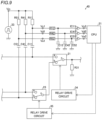
- FIGS. 4 to 10 The configuration of a power conversion device according to a second embodiment is now described with reference to FIGS. 4 to 10 .
- a welding detector having a configuration using common resistors for relays provided in series unlike the first embodiment is described.
- a welding detector 40 includes a CPU 31, relay drive circuits 34 and 35 (see FIG. 5 ), and an application unit 33. Furthermore, as shown in FIG. 4 , the welding detector 40 includes resistors R11, R12, R21, R22, R31, R32, R33, R41, R42, R51, R52, R61, R62, R71, R72, R81, R82, R91, and R92. The welding detector 40 includes capacitors C11, C12, C21, C22, C41, C42, C51, C52, C61, C62, C71, C72, C81, C82, C91, and C92.
- the welding detector 40 includes binarization units IC11, IC21, IC41, IC51, IC61, IC71, IC81, and IC91.
- the CPU 31 is an example of a “determiner” or a “controller” in the claims.
- the resistors R31, R32, and R33 are examples of a “first resistor” in the claims, and the resistors R11, R21, R41, R51, R61, R71, R81, and R91 are examples of a "second resistor" in the claims.
- the capacitor C11 is connected to a terminal a of a relay 21. That is, the capacitor C11 is connected to a power supply line.
- the resistor R11 is connected to the capacitor C11.
- the resistor R11 is connected to the application unit 33.
- the application unit 33 is connected to a ground.
- the resistor R12 is connected between the resistor R11 and the capacitor C11.
- the binarization unit IC11 is connected to the resistor R12.
- the CPU 31 is connected to the binarization unit IC11.
- the capacitor C12 is connected between the resistor R12 and the binarization unit IC11.
- the capacitor C12 is connected to the ground.
- the relay 21 is an example of a "second relay" in the claims.
- the capacitor C21 is connected to a terminal a of a relay 22. That is, the capacitor C21 is connected to the power supply line.
- the resistor R21 is connected to the capacitor C21. Furthermore, the resistor R21 is connected to the application unit 33.
- the resistor R22 is connected between the resistor R21 and the capacitor C21.
- the binarization unit IC21 is connected to the resistor R22.
- the CPU 31 is connected to the binarization unit IC21.
- the capacitor C22 is connected between the resistor R22 and the binarization unit IC21.
- the capacitor C22 is connected to the ground.
- the relay 22 is an example of a "second relay" in the claims.
- the resistor R31 is connected to a terminal c of the relay 21. Furthermore, the resistor R31 is connected to the ground.
- the resistor R32 is connected to a terminal c of the relay 22. Furthermore, the resistor R32 is connected to the ground.
- the capacitor C41 is connected to a terminal a of a relay 23. That is, the capacitor C41 is connected to the power supply line.
- the resistor R41 is connected to the capacitor C41. Furthermore, the resistor R41 is connected to the application unit 33.
- the resistor R42 is connected between the resistor R41 and the capacitor C41.
- the binarization unit IC41 is connected to the resistor R42.
- the CPU 31 is connected to the binarization unit IC41.
- the capacitor C42 is connected between the resistor R42 and the binarization unit IC41.
- the capacitor C42 is connected to the ground.
- the relay 23 is an example of a "first relay" in the claims.
- the capacitor C51 is connected to a terminal b of the relay 23. That is, the capacitor C51 is connected to the power supply line.
- the resistor R51 is connected to the capacitor C51. Furthermore, the resistor R51 is connected to the application unit 33.
- the resistor R52 is connected between the resistor R51 and the capacitor C51.
- the binarization unit IC51 is connected to the resistor R52.
- the CPU 31 is connected to the binarization unit IC51.
- the capacitor C52 is connected between the resistor R52 and the binarization unit IC51.
- the capacitor C52 is connected to the ground.
- the capacitor C61 is connected to a terminal a of a relay 24. That is, the capacitor C61 is connected to the power supply line.
- the resistor R61 is connected to the capacitor C61. Furthermore, the resistor R61 is connected to the application unit 33.
- the resistor R62 is connected between the resistor R61 and the capacitor C61.
- the binarization unit IC61 is connected to the resistor R62.
- the CPU 31 is connected to the binarization unit IC61.
- the capacitor C62 is connected between the resistor R62 and the binarization unit IC61.
- the capacitor C62 is connected to the ground.
- the capacitor C71 is connected to a terminal b of the relay 24. That is, the capacitor C71 is connected to the power supply line.
- the resistor R71 is connected to the capacitor C71. Furthermore, the resistor R71 is connected to the application unit 33.
- the resistor R72 is connected between the resistor R71 and the capacitor C71.
- the binarization unit IC71 is connected to the resistor R72.
- the CPU 31 is connected to the binarization unit IC71.
- the capacitor C72 is connected between the resistor R72 and the binarization unit IC71.
- the capacitor C72 is connected to the ground.
- the resistor R33 is connected to a terminal c of the relay 24. Furthermore, the resistor R33 is connected to the ground.
- the capacitor C81 is connected to a terminal a of a relay 25. That is, the capacitor C81 is connected to the power supply line.
- the resistor R81 is connected to the capacitor C81. Furthermore, the resistor R81 is connected to the application unit 33.
- the resistor R82 is connected between the resistor R81 and the capacitor C81.
- the binarization unit IC81 is connected to the resistor R82.
- the CPU 31 is connected to the binarization unit IC81.
- the capacitor C82 is connected between the resistor R82 and the binarization unit IC81.
- the capacitor C82 is connected to the ground.
- the relay 25 is an example of a "first relay" in the claims.
- a terminal c of the relay 23 (25) on a first side is connected to a terminal b of the relay 21 (22) on a second side.
- the common resistor R31 (R32) is provided at the terminal c of the relay 21 (22) on the first side
- the capacitor C41 (C81) and the resistor R41 (R81) are provided at the terminal a of the relay 23 (25) on the second side.
- the capacitor C51 (C91) and the resistor R51 (R91) are provided at the terminal b of the relay 23 (25) on the second side
- the capacitor C11 (C21) and the resistor R11 (R21) are provided at the terminal a of the relay 21 (22) on the second side.
- the CPU 31 determines whether or not the relay 23 (25) is welded based on signals input from the terminals a and b of the relay 23 (25) on the second side via the resistor R31 (R32) and the capacitor C41 or C51 (C81 or C91) and the resistor R41 or R51 (R81 or R91) provided at the terminal a or b of the relay 23 (25) on the second side in a state in which the terminal c of the relay 21 (22) on the first side and the terminal b of the relay 21 (22) on the second side are connected to each other.
- the welding detector 40 detects welding of the relays 21, 22, 23, and 25.
- FIGS. 5 , 7 , and 9 show the configuration in which the welding detector 40 is provided for the relays 21 and 23, the same applies to the relays 22 and 25.
- the welding detector for the relay 24 is the same as or similar to that of the first embodiment.
- the CPU 31 controls the application unit 33 to apply a pulse voltage.
- the terminal b of the relay 21 is not connected to the terminal c, and thus a voltage Vd1 (Ve1) has a first-order lag waveform due to the resistor R41 (R51), the resistor R42 (R52), and the capacitor C42 (C52).
- the terminal a of the relay 21 is connected to the terminal c, and thus a voltage Vc1 has a waveform (further delayed waveform) influenced by the capacitor C11 and the resistor R31 in addition to the resistor R11, the resistor R12, and the capacitor C12.
- a voltage Vc1 has a waveform (further delayed waveform) influenced by the capacitor C11 and the resistor R31 in addition to the resistor R11, the resistor R12, and the capacitor C12.
- the CPU 31 applies a pulse voltage from the application unit 33 in a state in which the relay 21 connects the terminal a to the terminal c to output a signal.
- the CPU 31 determines that the relay 21 is normal (not welded).
- the CPU 31 determines that the relay 21 is abnormal (welding has occurred).
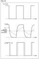
- the CPU 31 controls the application unit 33 to apply a pulse voltage.
- the terminal b of the relay 23 is not connected to the terminal c, and thus the voltage Ve1 has a first-order lag waveform due to the resistor R51, the resistor R52, and the capacitor C52.
- the terminal a of the relay 23 is connected to the terminal c, and thus the voltage Vd1 has a waveform (further delayed waveform) influenced by the capacitor C41 and the resistor R31 in addition to the resistor R41, the resistor R42, and the capacitor C42.
- the terminals b and a of the relay 23 There is the above difference between the terminals b and a of the relay 23, and thus there is a time difference between the outputs of the binarization unit IC41 and the binarization unit IC51.
- This time difference causes a waveform (voltage Vd2) on the side with which the relay 23 is conducting to be delayed with respect to a waveform (voltage Ve2) on the side not conducting with the relay 23. From the above, it is possible to determine the connected terminal (a or b) of the relay 23.
- the CPU 31 controls the application unit 33 to apply a pulse voltage.
- the terminal a of the relay 23 is not connected to the terminal c, and thus the voltage Vd1 has a first-order lag waveform due to the resistor R41, the resistor R42, and the capacitor C42.
- the terminal b of the relay 23 is connected to the terminal c, and thus the voltage Ve1 has a waveform (further delayed waveform) influenced by the capacitor C51 and the resistor R31 in addition to the resistor R51, the resistor R52, and the capacitor C52.
- the terminals a and b of the relay 23 There is the above difference between the terminals a and b of the relay 23, and thus there is a time difference between the outputs of the binarization unit IC41 and the binarization unit IC51. This time difference causes a waveform (voltage Ve2) on the side with which the relay 23 is conducting to be delayed with respect to a waveform (voltage Vd2) on the side not conducting with the relay 23. From the above, it is possible to determine the connected terminal (a or b) of the relay 23.
- a decrease in the reliability of the determiner (CPU 31) that determines whether or not the relay 21 (22 to 25) is welded can be significantly reduced or prevented.
- the CPU 31 determines whether or not the relay 21 (22) is welded based on the signals input from the terminals a and b of the relay 21 (22) on the second side via the resistor R31 (R32), the capacitor C41 or C51 (C81 or C91) and the resistor R41 or R51 (R81 or R91) provided at the terminal a or b of the relay 23 (25) on the second side, and the capacitor C11 (C21) and the resistor R11 (R21) provided at the terminal a of the relay 21 (22) on the second side.
- the common resistor R31 (R32) can be provided for the relay 23 (25) and the relay 21 (22), and thus it is not necessary to separately provide resistors for the relay 23 (25) and the relay 21 (22).
- the three capacitors C11, C41, and C51 (C21, C81, and C91) and the three resistors R11, R41, and R51 (R21, R81, and R91) are provided for the terminals a and b of the relay 23 (25) and the terminals a and b of the relay 21 (22), and thus it is not necessary to separately provide four capacitors and four resistors for the terminals a and b of the relay 23 (25) and the terminals a and b of the relay 21 (22).
- an increase in the number of components of the welding detector 40 can be significantly reduced or prevented, and the circuit configuration of the welding detector 40 can be simplified.
- the power conversion device is mounted on the electric vehicle in each of the aforementioned first and second embodiments, the present invention is not restricted to this.
- the power conversion device may alternatively be mounted on a hybrid vehicle driven by electricity and an engine or a fuel-cell vehicle that generates power by a fuel cell.
- the power conversion device may alternatively be mounted on a train.
- the power conversion device includes a plurality of relays, and the welding detector that detects welding of the plurality of relays is provided in each of the aforementioned first and second embodiments, the present invention is not restricted to this. In the present invention, a welding detector that detects welding of some of the plurality of relays may alternatively be provided.
- welding of the relays that switch connection destinations is detected in each of the aforementioned first and second embodiments
- the present invention is not restricted to this.
- welding of each relay that switches between an on-state and an off-state may alternatively be detected.
- the time length of a signal based on application of an inspection signal by an application unit may be detected, it may be detected that the relay is in the on-state when the time length of the signal is longer than a threshold (when the delay is large), and it may be detected that the relay is in the off-state when the time length of the signal is shorter than the threshold (when the delay is small).
- welding of the relays that select one from two connection destinations and switch connection destinations is detected in each of the aforementioned first and second embodiments, the present invention is not restricted to this. In the present invention, welding of each relay that selects one from three or more connection destinations and switches a connection destination may alternatively be detected.
- connection destinations of the relays are switched in switching between charging and discharging, and a discharging destination is switched by the relays in each of the aforementioned first and second embodiments
- the present invention is not restricted to this.
- a charging source may alternatively be switched by the relays.
Landscapes
- Engineering & Computer Science (AREA)
- Physics & Mathematics (AREA)
- General Physics & Mathematics (AREA)
- Mechanical Engineering (AREA)
- Power Engineering (AREA)
- Transportation (AREA)
- Sustainable Development (AREA)
- Sustainable Energy (AREA)
- Life Sciences & Earth Sciences (AREA)
- Inverter Devices (AREA)
- Protection Of Static Devices (AREA)
- Electric Propulsion And Braking For Vehicles (AREA)
- Power Conversion In General (AREA)
- Testing Of Short-Circuits, Discontinuities, Leakage, Or Incorrect Line Connections (AREA)
Claims (8)
- Dispositif de conversion de puissance (100) configuré de manière à être monté sur un véhicule (200), le dispositif de conversion de puissance (100) comprenant :un convertisseur de puissance (11, 12) configuré de manière à convertir une puissance fournie au véhicule (200) ;un relais (21, 22, 23, 24, 25) fourni sur une ligne d'alimentation électrique connectée au convertisseur de puissance ; etun détecteur de soudage (30) configuré de manière à détecter le soudage du relais ;dans lequel le détecteur de soudage inclut :
une première résistance (R301, R31, R32, R33) connectée à une borne du relais sur un premier côté ;caractérisé en ce que le détecteur de soudage inclut en outre :un condensateur (C101, C201, C11, C21, C41, C51, C61, C71, C81, C91) et une deuxième résistance (R101, R201, R11, R21, R41, R51, R61, R71, R81, R91), qui sont tous deux connectés à une borne du relais sur un deuxième côté ;une unité d'application (33) configurée de manière à appliquer un signal d'inspection au relais par l'intermédiaire du condensateur et de la deuxième résistance ; etun module de détermination (31) connecté entre le condensateur et la deuxième résistance, le module de détermination étant configuré de manière à détecter un signal sur la base de l'application du signal d'inspection par l'unité d'application afin de déterminer si le relais est soudé ou non ; etdans lequel le relais inclut, sur le deuxième côté, une première borne et une deuxième borne, et le relais est configuré de manière à commuter une borne connectée à la borne sur le premier côté entre la première borne et la deuxième borne. - Dispositif de conversion de puissance selon la revendication 1, dans lequelle condensateur, la deuxième résistance et le module de détermination sont connectés à la première borne et à la deuxième borne ; etle module de détermination du détecteur de soudage est configuré de manière à déterminer si le relais est soudé ou non sur la base de signaux appliqués en entrée à la fois à partir de la première borne et de la deuxième borne par l'application du signal d'inspection par l'unité d'application.
- Dispositif de conversion de puissance selon la revendication 2, dans lequel le module de détermination du détecteur de soudage est configuré de manière à déterminer si le relais est soudé ou non sur la base d'une différence de temps entre les signaux appliqués en entrée à la fois à partir de la première borne et de la deuxième borne par l'application du signal d'inspection par l'unité d'application.
- Dispositif de conversion de puissance selon l'une quelconque des revendications 1 à 3, dans lequel l'unité d'application du détecteur de soudage est configurée de manière à appliquer une tension d'impulsion au relais en tant que le signal d'inspection.
- Dispositif de conversion de puissance selon l'une quelconque des revendications 1 à 4, dans lequel le module de détermination comprend un contrôleur (31) configuré de manière à mettre en oeuvre une commande afin de détecter le signal sur la base de l'application du signal d'inspection par l'unité d'application en vue de déterminer si le relais est soudé ou non.
- Dispositif de conversion de puissance selon l'une quelconque des revendications 1 à 5, dans lequel le module de détermination est connecté entre le condensateur et la deuxième résistance par l'intermédiaire d'une unité de binarisation (IC101, IC201, IC11, IC21, IC41, IC51, IC61, IC71, IC81, IC91) configurée de manière à binariser le signal sur la base de l'application du signal d'inspection par l'unité d'application.
- Dispositif de conversion de puissance selon la revendication 6, dans lequel l'unité de binarisation est configurée de manière à binariser un signal décroissant à l'aide d'un premier seuil, et à binariser un signal croissant à l'aide d'un deuxième seuil, différent du premier seuil.
- Dispositif de conversion de puissance selon l'une quelconque des revendications 1 à 7, dans lequelle relais inclut un premier relais (23, 25) et un deuxième relais (21, 22) fournis en série dans la ligne d'alimentation électrique ;chacun du premier relais et du deuxième relais inclut, sur le deuxième côté, une première borne et une deuxième borne, et est configuré de manière à commuter une borne connectée à la borne sur le premier côté entre la première borne et la deuxième borne ;la borne du premier relais sur le premier côté est connectée à la première borne du deuxième relais sur le deuxième côté ;le détecteur de soudage inclut :une première résistance commune fournie au niveau de la borne du deuxième relais sur le premier côté ; etle condensateur et la deuxième résistance, qui sont tous deux fournis au niveau de chacune de la première borne du premier relais sur le deuxième côté, de la deuxième borne du premier relais sur le deuxième côté, et de la deuxième borne du deuxième relais sur le deuxième côté ; etle module de détermination est configuré de manière à, dans un état dans lequel la borne du deuxième relais sur le premier côté et la première borne du deuxième relais sur le deuxième côté sont connectées l'une à l'autre, déterminer si le premier relais est soudé ou non, sur la base de signaux appliqués en entrée à partir de la première borne et de la deuxième borne du premier relais sur le deuxième côté par l'intermédiaire de la première résistance, ains que du condensateur et de la deuxième résistance, qui sont tous deux fournis au niveau de chacune de la première borne et de la deuxième borne du premier relais sur le deuxième côté, et déterminer si le deuxième relais est soudé ou non, sur la base de signaux appliqués en entrée à partir de la première borne et de la deuxième borne du deuxième relais sur le deuxième côté par l'intermédiaire de la première résistance, ainsi que du condensateur et de la deuxième résistance, qui sont tous deux fournis au niveau de la première borne ou de la deuxième borne du premier relais sur le deuxième côté, ainsi que du condensateur et de la deuxième résistance, qui sont tous deux fournis au niveau de la deuxième borne du deuxième relais sur le deuxième côté.
Applications Claiming Priority (1)
| Application Number | Priority Date | Filing Date | Title |
|---|---|---|---|
| JP2020074010A JP7095016B2 (ja) | 2020-04-17 | 2020-04-17 | 電力変換装置 |
Publications (2)
| Publication Number | Publication Date |
|---|---|
| EP3904143A1 EP3904143A1 (fr) | 2021-11-03 |
| EP3904143B1 true EP3904143B1 (fr) | 2024-11-27 |
Family
ID=75339410
Family Applications (1)
| Application Number | Title | Priority Date | Filing Date |
|---|---|---|---|
| EP21165740.8A Active EP3904143B1 (fr) | 2020-04-17 | 2021-03-30 | Dispositif de conversion d'alimentation électrique |
Country Status (4)
| Country | Link |
|---|---|
| US (1) | US11703543B2 (fr) |
| EP (1) | EP3904143B1 (fr) |
| JP (1) | JP7095016B2 (fr) |
| CN (1) | CN113555918B (fr) |
Families Citing this family (1)
| Publication number | Priority date | Publication date | Assignee | Title |
|---|---|---|---|---|
| US12553957B2 (en) * | 2024-01-05 | 2026-02-17 | BorgWarner US Technologies LLC | Systems and methods for testing a capacitor in a circuit |
Family Cites Families (16)
| Publication number | Priority date | Publication date | Assignee | Title |
|---|---|---|---|---|
| JP3789819B2 (ja) | 2000-02-18 | 2006-06-28 | 三洋電機株式会社 | 電動車両のリレー溶着検出装置 |
| JP4894646B2 (ja) * | 2007-06-15 | 2012-03-14 | トヨタ自動車株式会社 | 充電装置および充電システム |
| JP5319400B2 (ja) * | 2009-05-28 | 2013-10-16 | アズビル株式会社 | リレー異常検出装置 |
| JP5533864B2 (ja) * | 2009-06-12 | 2014-06-25 | 日産自動車株式会社 | 地絡検出器の接続診断装置 |
| JP5087064B2 (ja) * | 2009-11-20 | 2012-11-28 | パナソニック株式会社 | 給電制御装置 |
| JP5381820B2 (ja) * | 2010-03-10 | 2014-01-08 | 株式会社デンソー | 電源制御装置 |
| JP5541743B2 (ja) * | 2011-09-21 | 2014-07-09 | オムロンオートモーティブエレクトロニクス株式会社 | コンタクタの溶着検出装置 |
| DE102012004843A1 (de) * | 2012-03-13 | 2013-09-19 | Phoenix Contact Gmbh & Co. Kg | Sicherheitsrelaisschaltung |
| JP5772784B2 (ja) * | 2012-10-19 | 2015-09-02 | トヨタ自動車株式会社 | 車両、電源システムおよび電源システムの制御方法 |
| KR101470098B1 (ko) * | 2012-12-18 | 2014-12-05 | 현대자동차주식회사 | 차량의 릴레이 고장진단 장치 및 방법 |
| US9236209B2 (en) * | 2013-04-03 | 2016-01-12 | Tektronix, Inc. | Relay failure detection system |
| JP2015065143A (ja) * | 2013-08-27 | 2015-04-09 | 株式会社日本自動車部品総合研究所 | 溶着検出システム |
| JP2016208580A (ja) * | 2015-04-16 | 2016-12-08 | トヨタ自動車株式会社 | リレー溶着判定装置 |
| JP6369407B2 (ja) * | 2015-07-09 | 2018-08-08 | 株式会社デンソー | 故障検知システム |
| JP6414520B2 (ja) * | 2015-07-14 | 2018-10-31 | 株式会社デンソー | 検査システム |
| JP2018196285A (ja) * | 2017-05-19 | 2018-12-06 | パナソニックIpマネジメント株式会社 | 電源制御装置、溶着検出方法およびリレー溶着検出装置 |
-
2020
- 2020-04-17 JP JP2020074010A patent/JP7095016B2/ja active Active
-
2021
- 2021-03-30 EP EP21165740.8A patent/EP3904143B1/fr active Active
- 2021-03-31 US US17/218,858 patent/US11703543B2/en active Active
- 2021-04-01 CN CN202110356781.8A patent/CN113555918B/zh active Active
Also Published As
| Publication number | Publication date |
|---|---|
| US11703543B2 (en) | 2023-07-18 |
| EP3904143A1 (fr) | 2021-11-03 |
| CN113555918B (zh) | 2025-07-11 |
| JP2021170905A (ja) | 2021-10-28 |
| JP7095016B2 (ja) | 2022-07-04 |
| CN113555918A (zh) | 2021-10-26 |
| US20210325463A1 (en) | 2021-10-21 |
Similar Documents
| Publication | Publication Date | Title |
|---|---|---|
| US10622685B2 (en) | Problem detection apparatus | |
| US10518725B2 (en) | Power distribution system | |
| US10895603B2 (en) | Voltage monitoring module and voltage monitoring system to detect a current leakage | |
| EP2991188B1 (fr) | Système de conversion d'énergie et connecteur | |
| US8513918B2 (en) | Vehicle battery control system having a voltage sensor that measures a voltage between a contactor and an inverter equipment | |
| US10775447B2 (en) | Ground fault detection apparatus | |
| US7564217B2 (en) | Battery pack manager and method of detecting a line cut | |
| US20110193413A1 (en) | Battery Control Device and Battery System | |
| US6657833B2 (en) | Relay welding detector and detecting method | |
| US12355295B2 (en) | Battery system and method for managing battery system | |
| US20170227589A1 (en) | Abnormality detection device and abnormality detection method | |
| US10879569B2 (en) | Battery pack and vehicle connected to battery pack | |
| US7019489B2 (en) | Capacity adjustment apparatus for battery pack and capacity adjustment method for battery pack | |
| US9551750B2 (en) | Monitoring system and vehicle | |
| JP5808678B2 (ja) | 電動車両 | |
| US10343524B2 (en) | Weld detection apparatus and weld detection method | |
| US20120286722A1 (en) | Charger | |
| US12391121B2 (en) | Vehicular power supply system | |
| EP4425201B1 (fr) | Procédé de diagnostic de blocage en position fermée et système de batterie l'utilisant | |
| JP6787705B2 (ja) | 異常検出装置、および組電池システム | |
| US20130021019A1 (en) | Device and method for detecting a polarity reversal on a low voltage side of a dc voltage transformer in a dual-voltage vehicle electrical system | |
| EP3904143A1 (fr) | Dispositif de conversion d'alimentation électrique | |
| EP4495611A1 (fr) | Dispositif de source d'alimentation | |
| EP4462142B1 (fr) | Système de batterie avec fonction de diagnostic du relais de batterie et véhicule équipé d'un tel système de batterie | |
| US20230118921A1 (en) | Monitoring device for battery |
Legal Events
| Date | Code | Title | Description |
|---|---|---|---|
| PUAI | Public reference made under article 153(3) epc to a published international application that has entered the european phase |
Free format text: ORIGINAL CODE: 0009012 |
|
| STAA | Information on the status of an ep patent application or granted ep patent |
Free format text: STATUS: REQUEST FOR EXAMINATION WAS MADE |
|
| 17P | Request for examination filed |
Effective date: 20210330 |
|
| AK | Designated contracting states |
Kind code of ref document: A1 Designated state(s): AL AT BE BG CH CY CZ DE DK EE ES FI FR GB GR HR HU IE IS IT LI LT LU LV MC MK MT NL NO PL PT RO RS SE SI SK SM TR |
|
| B565 | Issuance of search results under rule 164(2) epc |
Effective date: 20211001 |
|
| RIC1 | Information provided on ipc code assigned before grant |
Ipc: B60L 3/04 20060101AFI20240515BHEP |
|
| GRAP | Despatch of communication of intention to grant a patent |
Free format text: ORIGINAL CODE: EPIDOSNIGR1 |
|
| STAA | Information on the status of an ep patent application or granted ep patent |
Free format text: STATUS: GRANT OF PATENT IS INTENDED |
|
| INTG | Intention to grant announced |
Effective date: 20240624 |
|
| GRAS | Grant fee paid |
Free format text: ORIGINAL CODE: EPIDOSNIGR3 |
|
| GRAA | (expected) grant |
Free format text: ORIGINAL CODE: 0009210 |
|
| STAA | Information on the status of an ep patent application or granted ep patent |
Free format text: STATUS: THE PATENT HAS BEEN GRANTED |
|
| AK | Designated contracting states |
Kind code of ref document: B1 Designated state(s): AL AT BE BG CH CY CZ DE DK EE ES FI FR GB GR HR HU IE IS IT LI LT LU LV MC MK MT NL NO PL PT RO RS SE SI SK SM TR |
|
| REG | Reference to a national code |
Ref country code: GB Ref legal event code: FG4D |
|
| REG | Reference to a national code |
Ref country code: CH Ref legal event code: EP |
|
| REG | Reference to a national code |
Ref country code: IE Ref legal event code: FG4D |
|
| REG | Reference to a national code |
Ref country code: DE Ref legal event code: R096 Ref document number: 602021022281 Country of ref document: DE |
|
| REG | Reference to a national code |
Ref country code: LT Ref legal event code: MG9D |
|
| REG | Reference to a national code |
Ref country code: NL Ref legal event code: MP Effective date: 20241127 |
|
| PG25 | Lapsed in a contracting state [announced via postgrant information from national office to epo] |
Ref country code: PT Free format text: LAPSE BECAUSE OF FAILURE TO SUBMIT A TRANSLATION OF THE DESCRIPTION OR TO PAY THE FEE WITHIN THE PRESCRIBED TIME-LIMIT Effective date: 20250327 Ref country code: IS Free format text: LAPSE BECAUSE OF FAILURE TO SUBMIT A TRANSLATION OF THE DESCRIPTION OR TO PAY THE FEE WITHIN THE PRESCRIBED TIME-LIMIT Effective date: 20250327 Ref country code: HR Free format text: LAPSE BECAUSE OF FAILURE TO SUBMIT A TRANSLATION OF THE DESCRIPTION OR TO PAY THE FEE WITHIN THE PRESCRIBED TIME-LIMIT Effective date: 20241127 |
|
| PGFP | Annual fee paid to national office [announced via postgrant information from national office to epo] |
Ref country code: DE Payment date: 20250116 Year of fee payment: 5 |
|
| PG25 | Lapsed in a contracting state [announced via postgrant information from national office to epo] |
Ref country code: FI Free format text: LAPSE BECAUSE OF FAILURE TO SUBMIT A TRANSLATION OF THE DESCRIPTION OR TO PAY THE FEE WITHIN THE PRESCRIBED TIME-LIMIT Effective date: 20241127 Ref country code: NL Free format text: LAPSE BECAUSE OF FAILURE TO SUBMIT A TRANSLATION OF THE DESCRIPTION OR TO PAY THE FEE WITHIN THE PRESCRIBED TIME-LIMIT Effective date: 20241127 |
|
| REG | Reference to a national code |
Ref country code: AT Ref legal event code: MK05 Ref document number: 1745406 Country of ref document: AT Kind code of ref document: T Effective date: 20241127 |
|
| PG25 | Lapsed in a contracting state [announced via postgrant information from national office to epo] |
Ref country code: BG Free format text: LAPSE BECAUSE OF FAILURE TO SUBMIT A TRANSLATION OF THE DESCRIPTION OR TO PAY THE FEE WITHIN THE PRESCRIBED TIME-LIMIT Effective date: 20241127 |
|
| PG25 | Lapsed in a contracting state [announced via postgrant information from national office to epo] |
Ref country code: ES Free format text: LAPSE BECAUSE OF FAILURE TO SUBMIT A TRANSLATION OF THE DESCRIPTION OR TO PAY THE FEE WITHIN THE PRESCRIBED TIME-LIMIT Effective date: 20241127 |
|
| PG25 | Lapsed in a contracting state [announced via postgrant information from national office to epo] |
Ref country code: NO Free format text: LAPSE BECAUSE OF FAILURE TO SUBMIT A TRANSLATION OF THE DESCRIPTION OR TO PAY THE FEE WITHIN THE PRESCRIBED TIME-LIMIT Effective date: 20250227 |
|
| PG25 | Lapsed in a contracting state [announced via postgrant information from national office to epo] |
Ref country code: LV Free format text: LAPSE BECAUSE OF FAILURE TO SUBMIT A TRANSLATION OF THE DESCRIPTION OR TO PAY THE FEE WITHIN THE PRESCRIBED TIME-LIMIT Effective date: 20241127 Ref country code: AT Free format text: LAPSE BECAUSE OF FAILURE TO SUBMIT A TRANSLATION OF THE DESCRIPTION OR TO PAY THE FEE WITHIN THE PRESCRIBED TIME-LIMIT Effective date: 20241127 Ref country code: GR Free format text: LAPSE BECAUSE OF FAILURE TO SUBMIT A TRANSLATION OF THE DESCRIPTION OR TO PAY THE FEE WITHIN THE PRESCRIBED TIME-LIMIT Effective date: 20250228 |
|
| PG25 | Lapsed in a contracting state [announced via postgrant information from national office to epo] |
Ref country code: PL Free format text: LAPSE BECAUSE OF FAILURE TO SUBMIT A TRANSLATION OF THE DESCRIPTION OR TO PAY THE FEE WITHIN THE PRESCRIBED TIME-LIMIT Effective date: 20241127 |
|
| PG25 | Lapsed in a contracting state [announced via postgrant information from national office to epo] |
Ref country code: RS Free format text: LAPSE BECAUSE OF FAILURE TO SUBMIT A TRANSLATION OF THE DESCRIPTION OR TO PAY THE FEE WITHIN THE PRESCRIBED TIME-LIMIT Effective date: 20250227 |
|
| PG25 | Lapsed in a contracting state [announced via postgrant information from national office to epo] |
Ref country code: SM Free format text: LAPSE BECAUSE OF FAILURE TO SUBMIT A TRANSLATION OF THE DESCRIPTION OR TO PAY THE FEE WITHIN THE PRESCRIBED TIME-LIMIT Effective date: 20241127 |
|
| PG25 | Lapsed in a contracting state [announced via postgrant information from national office to epo] |
Ref country code: DK Free format text: LAPSE BECAUSE OF FAILURE TO SUBMIT A TRANSLATION OF THE DESCRIPTION OR TO PAY THE FEE WITHIN THE PRESCRIBED TIME-LIMIT Effective date: 20241127 |
|
| PG25 | Lapsed in a contracting state [announced via postgrant information from national office to epo] |
Ref country code: EE Free format text: LAPSE BECAUSE OF FAILURE TO SUBMIT A TRANSLATION OF THE DESCRIPTION OR TO PAY THE FEE WITHIN THE PRESCRIBED TIME-LIMIT Effective date: 20241127 |
|
| RAP4 | Party data changed (patent owner data changed or rights of a patent transferred) |
Owner name: FUJI ELECTRIC CO., LTD. Owner name: HONDA MOTOR CO., LTD. |
|
| PG25 | Lapsed in a contracting state [announced via postgrant information from national office to epo] |
Ref country code: RO Free format text: LAPSE BECAUSE OF FAILURE TO SUBMIT A TRANSLATION OF THE DESCRIPTION OR TO PAY THE FEE WITHIN THE PRESCRIBED TIME-LIMIT Effective date: 20241127 |
|
| PG25 | Lapsed in a contracting state [announced via postgrant information from national office to epo] |
Ref country code: SK Free format text: LAPSE BECAUSE OF FAILURE TO SUBMIT A TRANSLATION OF THE DESCRIPTION OR TO PAY THE FEE WITHIN THE PRESCRIBED TIME-LIMIT Effective date: 20241127 |
|
| PG25 | Lapsed in a contracting state [announced via postgrant information from national office to epo] |
Ref country code: CZ Free format text: LAPSE BECAUSE OF FAILURE TO SUBMIT A TRANSLATION OF THE DESCRIPTION OR TO PAY THE FEE WITHIN THE PRESCRIBED TIME-LIMIT Effective date: 20241127 |
|
| PG25 | Lapsed in a contracting state [announced via postgrant information from national office to epo] |
Ref country code: IT Free format text: LAPSE BECAUSE OF FAILURE TO SUBMIT A TRANSLATION OF THE DESCRIPTION OR TO PAY THE FEE WITHIN THE PRESCRIBED TIME-LIMIT Effective date: 20241127 |
|
| REG | Reference to a national code |
Ref country code: DE Ref legal event code: R097 Ref document number: 602021022281 Country of ref document: DE |
|
| PG25 | Lapsed in a contracting state [announced via postgrant information from national office to epo] |
Ref country code: SE Free format text: LAPSE BECAUSE OF FAILURE TO SUBMIT A TRANSLATION OF THE DESCRIPTION OR TO PAY THE FEE WITHIN THE PRESCRIBED TIME-LIMIT Effective date: 20241127 |
|
| PLBE | No opposition filed within time limit |
Free format text: ORIGINAL CODE: 0009261 |
|
| STAA | Information on the status of an ep patent application or granted ep patent |
Free format text: STATUS: NO OPPOSITION FILED WITHIN TIME LIMIT |
|
| REG | Reference to a national code |
Ref country code: CH Ref legal event code: L10 Free format text: ST27 STATUS EVENT CODE: U-0-0-L10-L00 (AS PROVIDED BY THE NATIONAL OFFICE) Effective date: 20251008 |
|
| PG25 | Lapsed in a contracting state [announced via postgrant information from national office to epo] |
Ref country code: MC Free format text: LAPSE BECAUSE OF FAILURE TO SUBMIT A TRANSLATION OF THE DESCRIPTION OR TO PAY THE FEE WITHIN THE PRESCRIBED TIME-LIMIT Effective date: 20241127 |
|
| REG | Reference to a national code |
Ref country code: CH Ref legal event code: H13 Free format text: ST27 STATUS EVENT CODE: U-0-0-H10-H13 (AS PROVIDED BY THE NATIONAL OFFICE) Effective date: 20251024 |
|
| 26N | No opposition filed |
Effective date: 20250828 |
|
| PG25 | Lapsed in a contracting state [announced via postgrant information from national office to epo] |
Ref country code: LU Free format text: LAPSE BECAUSE OF NON-PAYMENT OF DUE FEES Effective date: 20250330 |
|
| GBPC | Gb: european patent ceased through non-payment of renewal fee |
Effective date: 20250330 |
|
| REG | Reference to a national code |
Ref country code: BE Ref legal event code: MM Effective date: 20250331 |
|
| PG25 | Lapsed in a contracting state [announced via postgrant information from national office to epo] |
Ref country code: GB Free format text: LAPSE BECAUSE OF NON-PAYMENT OF DUE FEES Effective date: 20250330 |
|
| PG25 | Lapsed in a contracting state [announced via postgrant information from national office to epo] |
Ref country code: FR Free format text: LAPSE BECAUSE OF NON-PAYMENT OF DUE FEES Effective date: 20250331 |
|
| PG25 | Lapsed in a contracting state [announced via postgrant information from national office to epo] |
Ref country code: BE Free format text: LAPSE BECAUSE OF NON-PAYMENT OF DUE FEES Effective date: 20250331 |
|
| PG25 | Lapsed in a contracting state [announced via postgrant information from national office to epo] |
Ref country code: CH Free format text: LAPSE BECAUSE OF NON-PAYMENT OF DUE FEES Effective date: 20250331 |
|
| PG25 | Lapsed in a contracting state [announced via postgrant information from national office to epo] |
Ref country code: IE Free format text: LAPSE BECAUSE OF NON-PAYMENT OF DUE FEES Effective date: 20250330 |