EP3904186B1 - Dispositif de commande de déplacement de véhicule - Google Patents
Dispositif de commande de déplacement de véhicule Download PDFInfo
- Publication number
- EP3904186B1 EP3904186B1 EP20783611.5A EP20783611A EP3904186B1 EP 3904186 B1 EP3904186 B1 EP 3904186B1 EP 20783611 A EP20783611 A EP 20783611A EP 3904186 B1 EP3904186 B1 EP 3904186B1
- Authority
- EP
- European Patent Office
- Prior art keywords
- vehicle
- route
- controller
- traveling
- outdoor environment
- Prior art date
- Legal status (The legal status is an assumption and is not a legal conclusion. Google has not performed a legal analysis and makes no representation as to the accuracy of the status listed.)
- Active
Links
Images


Classifications
-
- B—PERFORMING OPERATIONS; TRANSPORTING
- B60—VEHICLES IN GENERAL
- B60W—CONJOINT CONTROL OF VEHICLE SUB-UNITS OF DIFFERENT TYPE OR DIFFERENT FUNCTION; CONTROL SYSTEMS SPECIALLY ADAPTED FOR HYBRID VEHICLES; ROAD VEHICLE DRIVE CONTROL SYSTEMS FOR PURPOSES NOT RELATED TO THE CONTROL OF A PARTICULAR SUB-UNIT
- B60W50/00—Details of control systems for road vehicle drive control not related to the control of a particular sub-unit, e.g. process diagnostic or vehicle driver interfaces
- B60W50/02—Ensuring safety in case of control system failures, e.g. by diagnosing, circumventing or fixing failures
- B60W50/0225—Failure correction strategy
-
- B—PERFORMING OPERATIONS; TRANSPORTING
- B62—LAND VEHICLES FOR TRAVELLING OTHERWISE THAN ON RAILS
- B62D—MOTOR VEHICLES; TRAILERS
- B62D15/00—Steering not otherwise provided for
- B62D15/02—Steering position indicators ; Steering position determination; Steering aids
- B62D15/025—Active steering aids, e.g. helping the driver by actively influencing the steering system after environment evaluation
- B62D15/0265—Automatic obstacle avoidance by steering
-
- B—PERFORMING OPERATIONS; TRANSPORTING
- B60—VEHICLES IN GENERAL
- B60T—VEHICLE BRAKE CONTROL SYSTEMS OR PARTS THEREOF; BRAKE CONTROL SYSTEMS OR PARTS THEREOF, IN GENERAL; ARRANGEMENT OF BRAKING ELEMENTS ON VEHICLES IN GENERAL; PORTABLE DEVICES FOR PREVENTING UNWANTED MOVEMENT OF VEHICLES; VEHICLE MODIFICATIONS TO FACILITATE COOLING OF BRAKES
- B60T7/00—Brake-action initiating means
- B60T7/12—Brake-action initiating means for automatic initiation; for initiation not subject to will of driver or passenger
- B60T7/22—Brake-action initiating means for automatic initiation; for initiation not subject to will of driver or passenger initiated by contact of vehicle, e.g. bumper, with an external object, e.g. another vehicle, or by means of contactless obstacle detectors mounted on the vehicle
-
- B—PERFORMING OPERATIONS; TRANSPORTING
- B60—VEHICLES IN GENERAL
- B60T—VEHICLE BRAKE CONTROL SYSTEMS OR PARTS THEREOF; BRAKE CONTROL SYSTEMS OR PARTS THEREOF, IN GENERAL; ARRANGEMENT OF BRAKING ELEMENTS ON VEHICLES IN GENERAL; PORTABLE DEVICES FOR PREVENTING UNWANTED MOVEMENT OF VEHICLES; VEHICLE MODIFICATIONS TO FACILITATE COOLING OF BRAKES
- B60T8/00—Arrangements for adjusting wheel-braking force to meet varying vehicular or ground-surface conditions, e.g. limiting or varying distribution of braking force
- B60T8/17—Using electrical or electronic regulation means to control braking
- B60T8/1755—Brake regulation specially adapted to control the stability of the vehicle, e.g. taking into account yaw rate or transverse acceleration in a curve
- B60T8/17555—Brake regulation specially adapted to control the stability of the vehicle, e.g. taking into account yaw rate or transverse acceleration in a curve specially adapted for enhancing driver or passenger comfort, e.g. soft intervention or pre-actuation strategies
-
- B—PERFORMING OPERATIONS; TRANSPORTING
- B60—VEHICLES IN GENERAL
- B60W—CONJOINT CONTROL OF VEHICLE SUB-UNITS OF DIFFERENT TYPE OR DIFFERENT FUNCTION; CONTROL SYSTEMS SPECIALLY ADAPTED FOR HYBRID VEHICLES; ROAD VEHICLE DRIVE CONTROL SYSTEMS FOR PURPOSES NOT RELATED TO THE CONTROL OF A PARTICULAR SUB-UNIT
- B60W10/00—Conjoint control of vehicle sub-units of different type or different function
- B60W10/04—Conjoint control of vehicle sub-units of different type or different function including control of propulsion units
-
- B—PERFORMING OPERATIONS; TRANSPORTING
- B60—VEHICLES IN GENERAL
- B60W—CONJOINT CONTROL OF VEHICLE SUB-UNITS OF DIFFERENT TYPE OR DIFFERENT FUNCTION; CONTROL SYSTEMS SPECIALLY ADAPTED FOR HYBRID VEHICLES; ROAD VEHICLE DRIVE CONTROL SYSTEMS FOR PURPOSES NOT RELATED TO THE CONTROL OF A PARTICULAR SUB-UNIT
- B60W10/00—Conjoint control of vehicle sub-units of different type or different function
- B60W10/18—Conjoint control of vehicle sub-units of different type or different function including control of braking systems
-
- B—PERFORMING OPERATIONS; TRANSPORTING
- B60—VEHICLES IN GENERAL
- B60W—CONJOINT CONTROL OF VEHICLE SUB-UNITS OF DIFFERENT TYPE OR DIFFERENT FUNCTION; CONTROL SYSTEMS SPECIALLY ADAPTED FOR HYBRID VEHICLES; ROAD VEHICLE DRIVE CONTROL SYSTEMS FOR PURPOSES NOT RELATED TO THE CONTROL OF A PARTICULAR SUB-UNIT
- B60W10/00—Conjoint control of vehicle sub-units of different type or different function
- B60W10/20—Conjoint control of vehicle sub-units of different type or different function including control of steering systems
-
- B—PERFORMING OPERATIONS; TRANSPORTING
- B60—VEHICLES IN GENERAL
- B60W—CONJOINT CONTROL OF VEHICLE SUB-UNITS OF DIFFERENT TYPE OR DIFFERENT FUNCTION; CONTROL SYSTEMS SPECIALLY ADAPTED FOR HYBRID VEHICLES; ROAD VEHICLE DRIVE CONTROL SYSTEMS FOR PURPOSES NOT RELATED TO THE CONTROL OF A PARTICULAR SUB-UNIT
- B60W30/00—Purposes of road vehicle drive control systems not related to the control of a particular sub-unit, e.g. of systems using conjoint control of vehicle sub-units
- B60W30/02—Control of vehicle driving stability
- B60W30/025—Control of vehicle driving stability related to comfort of drivers or passengers
-
- B—PERFORMING OPERATIONS; TRANSPORTING
- B60—VEHICLES IN GENERAL
- B60W—CONJOINT CONTROL OF VEHICLE SUB-UNITS OF DIFFERENT TYPE OR DIFFERENT FUNCTION; CONTROL SYSTEMS SPECIALLY ADAPTED FOR HYBRID VEHICLES; ROAD VEHICLE DRIVE CONTROL SYSTEMS FOR PURPOSES NOT RELATED TO THE CONTROL OF A PARTICULAR SUB-UNIT
- B60W30/00—Purposes of road vehicle drive control systems not related to the control of a particular sub-unit, e.g. of systems using conjoint control of vehicle sub-units
- B60W30/18—Propelling the vehicle
- B60W30/18172—Preventing, or responsive to skidding of wheels
-
- B—PERFORMING OPERATIONS; TRANSPORTING
- B60—VEHICLES IN GENERAL
- B60W—CONJOINT CONTROL OF VEHICLE SUB-UNITS OF DIFFERENT TYPE OR DIFFERENT FUNCTION; CONTROL SYSTEMS SPECIALLY ADAPTED FOR HYBRID VEHICLES; ROAD VEHICLE DRIVE CONTROL SYSTEMS FOR PURPOSES NOT RELATED TO THE CONTROL OF A PARTICULAR SUB-UNIT
- B60W40/00—Estimation or calculation of non-directly measurable driving parameters for road vehicle drive control systems not related to the control of a particular sub unit, e.g. by using mathematical models
- B60W40/02—Estimation or calculation of non-directly measurable driving parameters for road vehicle drive control systems not related to the control of a particular sub unit, e.g. by using mathematical models related to ambient conditions
-
- B—PERFORMING OPERATIONS; TRANSPORTING
- B60—VEHICLES IN GENERAL
- B60W—CONJOINT CONTROL OF VEHICLE SUB-UNITS OF DIFFERENT TYPE OR DIFFERENT FUNCTION; CONTROL SYSTEMS SPECIALLY ADAPTED FOR HYBRID VEHICLES; ROAD VEHICLE DRIVE CONTROL SYSTEMS FOR PURPOSES NOT RELATED TO THE CONTROL OF A PARTICULAR SUB-UNIT
- B60W50/00—Details of control systems for road vehicle drive control not related to the control of a particular sub-unit, e.g. process diagnostic or vehicle driver interfaces
- B60W50/0097—Predicting future conditions
-
- B—PERFORMING OPERATIONS; TRANSPORTING
- B60—VEHICLES IN GENERAL
- B60W—CONJOINT CONTROL OF VEHICLE SUB-UNITS OF DIFFERENT TYPE OR DIFFERENT FUNCTION; CONTROL SYSTEMS SPECIALLY ADAPTED FOR HYBRID VEHICLES; ROAD VEHICLE DRIVE CONTROL SYSTEMS FOR PURPOSES NOT RELATED TO THE CONTROL OF A PARTICULAR SUB-UNIT
- B60W50/00—Details of control systems for road vehicle drive control not related to the control of a particular sub-unit, e.g. process diagnostic or vehicle driver interfaces
- B60W50/02—Ensuring safety in case of control system failures, e.g. by diagnosing, circumventing or fixing failures
- B60W50/0205—Diagnosing or detecting failures; Failure detection models
-
- B—PERFORMING OPERATIONS; TRANSPORTING
- B60—VEHICLES IN GENERAL
- B60W—CONJOINT CONTROL OF VEHICLE SUB-UNITS OF DIFFERENT TYPE OR DIFFERENT FUNCTION; CONTROL SYSTEMS SPECIALLY ADAPTED FOR HYBRID VEHICLES; ROAD VEHICLE DRIVE CONTROL SYSTEMS FOR PURPOSES NOT RELATED TO THE CONTROL OF A PARTICULAR SUB-UNIT
- B60W60/00—Drive control systems specially adapted for autonomous road vehicles
- B60W60/001—Planning or execution of driving tasks
-
- B—PERFORMING OPERATIONS; TRANSPORTING
- B62—LAND VEHICLES FOR TRAVELLING OTHERWISE THAN ON RAILS
- B62D—MOTOR VEHICLES; TRAILERS
- B62D15/00—Steering not otherwise provided for
- B62D15/02—Steering position indicators ; Steering position determination; Steering aids
- B62D15/025—Active steering aids, e.g. helping the driver by actively influencing the steering system after environment evaluation
-
- G—PHYSICS
- G06—COMPUTING OR CALCULATING; COUNTING
- G06N—COMPUTING ARRANGEMENTS BASED ON SPECIFIC COMPUTATIONAL MODELS
- G06N3/00—Computing arrangements based on biological models
- G06N3/02—Neural networks
- G06N3/04—Architecture, e.g. interconnection topology
- G06N3/0464—Convolutional networks [CNN, ConvNet]
-
- G—PHYSICS
- G06—COMPUTING OR CALCULATING; COUNTING
- G06N—COMPUTING ARRANGEMENTS BASED ON SPECIFIC COMPUTATIONAL MODELS
- G06N3/00—Computing arrangements based on biological models
- G06N3/02—Neural networks
- G06N3/08—Learning methods
-
- G—PHYSICS
- G06—COMPUTING OR CALCULATING; COUNTING
- G06N—COMPUTING ARRANGEMENTS BASED ON SPECIFIC COMPUTATIONAL MODELS
- G06N3/00—Computing arrangements based on biological models
- G06N3/02—Neural networks
- G06N3/08—Learning methods
- G06N3/09—Supervised learning
-
- B—PERFORMING OPERATIONS; TRANSPORTING
- B60—VEHICLES IN GENERAL
- B60T—VEHICLE BRAKE CONTROL SYSTEMS OR PARTS THEREOF; BRAKE CONTROL SYSTEMS OR PARTS THEREOF, IN GENERAL; ARRANGEMENT OF BRAKING ELEMENTS ON VEHICLES IN GENERAL; PORTABLE DEVICES FOR PREVENTING UNWANTED MOVEMENT OF VEHICLES; VEHICLE MODIFICATIONS TO FACILITATE COOLING OF BRAKES
- B60T2210/00—Detection or estimation of road or environment conditions; Detection or estimation of road shapes
- B60T2210/10—Detection or estimation of road conditions
- B60T2210/14—Rough roads, bad roads, gravel roads
-
- B—PERFORMING OPERATIONS; TRANSPORTING
- B60—VEHICLES IN GENERAL
- B60T—VEHICLE BRAKE CONTROL SYSTEMS OR PARTS THEREOF; BRAKE CONTROL SYSTEMS OR PARTS THEREOF, IN GENERAL; ARRANGEMENT OF BRAKING ELEMENTS ON VEHICLES IN GENERAL; PORTABLE DEVICES FOR PREVENTING UNWANTED MOVEMENT OF VEHICLES; VEHICLE MODIFICATIONS TO FACILITATE COOLING OF BRAKES
- B60T2210/00—Detection or estimation of road or environment conditions; Detection or estimation of road shapes
- B60T2210/30—Environment conditions or position therewithin
-
- B—PERFORMING OPERATIONS; TRANSPORTING
- B60—VEHICLES IN GENERAL
- B60T—VEHICLE BRAKE CONTROL SYSTEMS OR PARTS THEREOF; BRAKE CONTROL SYSTEMS OR PARTS THEREOF, IN GENERAL; ARRANGEMENT OF BRAKING ELEMENTS ON VEHICLES IN GENERAL; PORTABLE DEVICES FOR PREVENTING UNWANTED MOVEMENT OF VEHICLES; VEHICLE MODIFICATIONS TO FACILITATE COOLING OF BRAKES
- B60T2210/00—Detection or estimation of road or environment conditions; Detection or estimation of road shapes
- B60T2210/30—Environment conditions or position therewithin
- B60T2210/32—Vehicle surroundings
-
- B—PERFORMING OPERATIONS; TRANSPORTING
- B60—VEHICLES IN GENERAL
- B60T—VEHICLE BRAKE CONTROL SYSTEMS OR PARTS THEREOF; BRAKE CONTROL SYSTEMS OR PARTS THEREOF, IN GENERAL; ARRANGEMENT OF BRAKING ELEMENTS ON VEHICLES IN GENERAL; PORTABLE DEVICES FOR PREVENTING UNWANTED MOVEMENT OF VEHICLES; VEHICLE MODIFICATIONS TO FACILITATE COOLING OF BRAKES
- B60T2210/00—Detection or estimation of road or environment conditions; Detection or estimation of road shapes
- B60T2210/30—Environment conditions or position therewithin
- B60T2210/36—Global Positioning System [GPS]
-
- B—PERFORMING OPERATIONS; TRANSPORTING
- B60—VEHICLES IN GENERAL
- B60W—CONJOINT CONTROL OF VEHICLE SUB-UNITS OF DIFFERENT TYPE OR DIFFERENT FUNCTION; CONTROL SYSTEMS SPECIALLY ADAPTED FOR HYBRID VEHICLES; ROAD VEHICLE DRIVE CONTROL SYSTEMS FOR PURPOSES NOT RELATED TO THE CONTROL OF A PARTICULAR SUB-UNIT
- B60W2420/00—Indexing codes relating to the type of sensors based on the principle of their operation
- B60W2420/40—Photo, light or radio wave sensitive means, e.g. infrared sensors
- B60W2420/403—Image sensing, e.g. optical camera
-
- B—PERFORMING OPERATIONS; TRANSPORTING
- B60—VEHICLES IN GENERAL
- B60W—CONJOINT CONTROL OF VEHICLE SUB-UNITS OF DIFFERENT TYPE OR DIFFERENT FUNCTION; CONTROL SYSTEMS SPECIALLY ADAPTED FOR HYBRID VEHICLES; ROAD VEHICLE DRIVE CONTROL SYSTEMS FOR PURPOSES NOT RELATED TO THE CONTROL OF A PARTICULAR SUB-UNIT
- B60W2420/00—Indexing codes relating to the type of sensors based on the principle of their operation
- B60W2420/40—Photo, light or radio wave sensitive means, e.g. infrared sensors
- B60W2420/408—Radar; Laser, e.g. lidar
-
- B—PERFORMING OPERATIONS; TRANSPORTING
- B60—VEHICLES IN GENERAL
- B60W—CONJOINT CONTROL OF VEHICLE SUB-UNITS OF DIFFERENT TYPE OR DIFFERENT FUNCTION; CONTROL SYSTEMS SPECIALLY ADAPTED FOR HYBRID VEHICLES; ROAD VEHICLE DRIVE CONTROL SYSTEMS FOR PURPOSES NOT RELATED TO THE CONTROL OF A PARTICULAR SUB-UNIT
- B60W2540/00—Input parameters relating to occupants
- B60W2540/01—Occupants other than the driver
-
- B—PERFORMING OPERATIONS; TRANSPORTING
- B60—VEHICLES IN GENERAL
- B60W—CONJOINT CONTROL OF VEHICLE SUB-UNITS OF DIFFERENT TYPE OR DIFFERENT FUNCTION; CONTROL SYSTEMS SPECIALLY ADAPTED FOR HYBRID VEHICLES; ROAD VEHICLE DRIVE CONTROL SYSTEMS FOR PURPOSES NOT RELATED TO THE CONTROL OF A PARTICULAR SUB-UNIT
- B60W2540/00—Input parameters relating to occupants
- B60W2540/221—Physiology, e.g. weight, heartbeat, health or special needs
-
- B—PERFORMING OPERATIONS; TRANSPORTING
- B60—VEHICLES IN GENERAL
- B60W—CONJOINT CONTROL OF VEHICLE SUB-UNITS OF DIFFERENT TYPE OR DIFFERENT FUNCTION; CONTROL SYSTEMS SPECIALLY ADAPTED FOR HYBRID VEHICLES; ROAD VEHICLE DRIVE CONTROL SYSTEMS FOR PURPOSES NOT RELATED TO THE CONTROL OF A PARTICULAR SUB-UNIT
- B60W2556/00—Input parameters relating to data
- B60W2556/45—External transmission of data to or from the vehicle
- B60W2556/50—External transmission of data to or from the vehicle of positioning data, e.g. GPS [Global Positioning System] data
-
- B—PERFORMING OPERATIONS; TRANSPORTING
- B60—VEHICLES IN GENERAL
- B60W—CONJOINT CONTROL OF VEHICLE SUB-UNITS OF DIFFERENT TYPE OR DIFFERENT FUNCTION; CONTROL SYSTEMS SPECIALLY ADAPTED FOR HYBRID VEHICLES; ROAD VEHICLE DRIVE CONTROL SYSTEMS FOR PURPOSES NOT RELATED TO THE CONTROL OF A PARTICULAR SUB-UNIT
- B60W2710/00—Output or target parameters relating to a particular sub-units
- B60W2710/18—Braking system
-
- B—PERFORMING OPERATIONS; TRANSPORTING
- B60—VEHICLES IN GENERAL
- B60W—CONJOINT CONTROL OF VEHICLE SUB-UNITS OF DIFFERENT TYPE OR DIFFERENT FUNCTION; CONTROL SYSTEMS SPECIALLY ADAPTED FOR HYBRID VEHICLES; ROAD VEHICLE DRIVE CONTROL SYSTEMS FOR PURPOSES NOT RELATED TO THE CONTROL OF A PARTICULAR SUB-UNIT
- B60W2710/00—Output or target parameters relating to a particular sub-units
- B60W2710/20—Steering systems
Definitions
- the technique disclosed here relates to a technology concerning a vehicle travel control device.
- a vehicle travel control device known to date controls a plurality of on-vehicle device for travel mounted on a vehicle.
- Japanese Patent Application Publication No. 2017-61278 describes a control system that is hierarchized into device control parts for controlling a plurality of on-vehicle devices and domain control parts for managing the device control parts in a plurality of domains previously defined in accordance with functions of the on-vehicle devices.
- the control system also includes an integrated control part located at a higher rank than the domain control parts and manages the domain control parts.
- the device control parts calculate controlled variables of the corresponding on-vehicle devices, and output control signals for achieving the controlled variables to the on-vehicle devices.
- Document US 2017/217276 A1 shows a method for improving the safety and comfort of a vehicle driving over a railroad track, cattle guard, or the like.
- the method may include receiving, by a computer system, one or more inputs corresponding to one or more forward looking sensors.
- the computer system may also receive data characterizing a motion of the vehicle.
- the computer system may estimate, based on the one or more inputs and the data, a motion of a vehicle with respect to a railroad track, cattle guard, or the like extending across a road ahead of the vehicle.
- EP 3 159 853 A1 shows a driver assistance system is presented, including an event detector which comprises a set of rules defining a surprising event based on signals reflecting a vehicle operator input and signals from an object detection sensor.
- An event data file generator is configured to generate an event data file according to rules comprised in the event detector, the event data file comprising a video signal received from a camera, a signal from at least one dynamic vehicle sensor, and target object information received from the object detection sensor.
- the event data file generator is further configured to initiate data file generation responsive to a surprising event being detected by the event generator, and wherein the contents of the data file are specified by the rules comprised in the event detector.
- surprising events may be collected and analyzed off-board in order to generate updates for the driver assistance system.
- WO 2019/044645 A1 shows a travel route control unit 10a that updates a target travel route of a vehicle, and an automatic emergency avoidance control unit that executes an automatic emergency avoidance control process for automatically operating a prescribed control system in order to avoid a collision with an obstacle.
- the travel route control unit calculates a plurality of correction travel routes that correct the target travel route R and avoid the obstacle, evaluates the correction travel routes using a prescribed evaluation function, and selects one correction travel route.
- the travel route control unit generates a first requirement signal so that the vehicle travels on the correction travel route.
- the automatic emergency avoidance control unit generates a second requirement signal.
- An output control unit outputs the first or second requirement signal to a prescribed control system.
- vehicle outdoor environment information is acquired by a camera or other devices, and based on the acquired vehicle outdoor environment information, a route on which a vehicle is to travel is calculated.
- traveling devices are controlled in order to follow the route to be traveled.
- traveling devices need to be controlled precisely in accordance with conditions such as a road condition, and thus, the control of the traveling devices needs to be performed as fast as possible.
- a large number of traveling devices are employed, such as an ignition plug, a fuel injection valve, and a valve mechanism for intake and exhaust valves, in an engine alone.
- the amount of calculation is enormous, and it takes time before outputting control signals to the traveling devices. Consequently, responsiveness of the traveling devices to vehicle outdoor environments might degrade.
- the technique disclosed here has been made in view of the foregoing situations, and has an object of enhancing responsiveness of a traveling device to vehicle outdoor environments in a vehicle travel control device that controls actuation of the traveling device so as to follow a route calculated by a computation device.
- An object of the present invention is a vehicle travel control device according to independent claim 1.
- the technique disclosed here provides a configuration of a vehicle travel control device including: a computation device; and a device controller configured to control actuation of a traveling device mounted on the vehicle, based on a computation result of the computation device, wherein the computation device includes a vehicle outdoor environment identifier configured to identify a vehicle outdoor environment based on an output from an image acquirer, the image acquirer being configured to acquire a vehicle outdoor environment, a route setter configured to set a route on which the vehicle is to be travel, in accordance with the vehicle outdoor environment identified by the vehicle outdoor environment identifier, a target motion determiner configured to determine a target motion of the vehicle for following the route set by the route setter, and a physical quantity calculator configured to calculate a target physical quantity to be generated by the traveling device, in order to achieve the target motion determined by the target motion determiner, and the device controller calculates a controlled variable of the traveling device such that the target physical quantity calculated by the physical quantity calculator is achieved, and the device controller outputs a control signal to the traveling device.
- the computation device includes
- the computation device only calculates the physical quantity to be achieved, and an actual controlled variable of the traveling device is calculated by the device controller. Accordingly, the amount of calculation of the computation device decreases so that the calculation speed of the computation device can be increased.
- the device controller only needs to calculate an actual controlled variable and output a control signal to the traveling device. Thus, a processing speed thereof is high. Consequently, responsiveness of the traveling device to the vehicle outdoor environment can be increased.
- the computation device Since the device controller calculates the controlled variable, the computation device only needs to calculate a rough physical quantity. Thus, the computation speed may be lower than that of the device controller. As a result, computation accuracy of the computation device can be enhanced.
- the vehicle travel control device can cope with a slight change of the vehicle outdoor environment by adjusting the controlled variable by using the device controller without using the computation device.
- traveling devices refer to devices such as actuators and sensors that are controlled while the vehicle travels.
- the vehicle travel control device for automobile of the present invention further includes an abnormality detector configured to detect an abnormality in traveling of the vehicle, wherein the abnormality detector is a sensor and inputs a detection signal to the device controller when detecting an abnormality and when a detection signal is input from the abnormality detector to the device controller , the device controller calculates a controlled variable of the traveling device in order to eliminate or reduce the abnormality, and outputs a control signal to traveling device.
- an abnormality detector configured to detect an abnormality in traveling of the vehicle, wherein the abnormality detector is a sensor and inputs a detection signal to the device controller when detecting an abnormality and when a detection signal is input from the abnormality detector to the device controller , the device controller calculates a controlled variable of the traveling device in order to eliminate or reduce the abnormality, and outputs a control signal to traveling device.
- the device controller calculates a controlled variable for eliminating or reducing the abnormality without waiting for calculation of the computation device, and outputs a control signal to the traveling device. Consequently, responsiveness of the traveling device to the vehicle outdoor environment can be further enhanced.
- the traveling device comprises a power train-related device constituting a power train device, a brake-related device constituting a braking device, and a steering-related device constituting a steering device
- the device controller comprises a power train controller configured to control actuation of the power train-related device, a brake controller configured to control actuation of the brake-related device, and a steering controller configured to control actuation of the steering-related device
- the power train controller, the brake controller, and the steering controller are configured to be communicable with one another, and share information on physical quantities generated by the power train controller, the brake controller, and the steering controller.
- controlled variables of the power train-related device and the brake-related device are finely adjusted in accordance with a target steering variable of the steering device so that an appropriate lateral force can be applied to the vehicle, and smooth cornering can be performed.
- responsiveness of the traveling device to the vehicle outdoor environment can be further enhanced.
- the vehicle outdoor environment identifier may identify a vehicle outdoor environment by using deep learning.
- the computation device performs an especially large amount of computation.
- the controlled variable of the traveling device is calculated by the device controller other than the computation device so that the advantage of further enhancing responsiveness of the traveling device to the vehicle outdoor environment can be more appropriately obtained.
- the technique disclosed here can enhance responsiveness of a traveling device to vehicle outdoor environment in a vehicle travel control device that controls operation of the traveling device so as to follow a route calculated by a computation device.
- a “traveling device” described later in this embodiment refers to devices such as actuators and sensors that are controlled when a vehicle 1 travels.
- FIG. 1 schematically illustrates a configuration of the vehicle 1 that is controlled by a vehicle travel control device 100 (hereinafter referred to as a travel control device 100) according to this embodiment.
- the vehicle 1 is an automobile capable of operating in manual driving of traveling in accordance with an operation of, for example, an accelerator by a driver, assisted driving of traveling while assisting an operation by the driver, and automated driving of traveling without an operation by the driver.
- the vehicle 1 includes an engine 10 serving as a driving source and including a plurality of (four in this embodiment) cylinders 11, a transmission 20 coupled to the engine 10, a braking device 30 that brakes rotation of front wheels 50 as driving wheel, and a steering device 40 that steers the front wheels 50 as steered wheels.
- an engine 10 serving as a driving source and including a plurality of (four in this embodiment) cylinders 11, a transmission 20 coupled to the engine 10, a braking device 30 that brakes rotation of front wheels 50 as driving wheel, and a steering device 40 that steers the front wheels 50 as steered wheels.
- the engine 10 is, for example, a gasoline engine. As illustrated in FIG. 2 , each of the cylinders 11 of the engine 10 is provided with an injector 12 for supplying fuel into the cylinder 11 and an ignition plug 13 for igniting an air-fuel mixture of fuel and intake air supplied into the cylinder 11.
- the engine 10 includes, for each of the cylinders 11, an intake valve 14, an exhaust valve 15, and a valve mechanism 16 for adjusting opening/closing operations of the intake valve 14 and the exhaust valve 15.
- the engine 10 also includes a piston 17 that reciprocates in the cylinders 11, and a crankshaft 18 coupled to the piston 17 through a connecting rod.
- the engine 10 may be a diesel engine. In the case where the engine 10 is the diesel engine, the ignition plug 13 may not be provided.
- the injector 12, the ignition plug 13, and the valve mechanism 16 are examples of power train-related devices.
- the transmission 20 is, for example, a multistep automatic transmission.
- the transmission 20 is disposed at one side of the cylinder line of the engine 10.
- the transmission 20 includes an input shaft (not shown) coupled to the crankshaft 18 of the engine 10 and an output shaft (not shown) coupled to the input shaft through a plurality of speed-reducing gears (not shown).
- the output shaft is coupled to an axle 51 of the front wheels 50. Rotation of the crankshaft 18 is subjected to a gear shift by the transmission 20, and is transferred to the front wheels 50.
- the transmission 20 is an example of a power train-related device.
- the engine 10 and the transmission 20 are power train devices that generate a driving force for enabling the vehicle 1 to travel. Actuation of the engine 10 and the transmission 20 is controlled by a power train electric control unit (ECU) 200.
- ECU power train electric control unit
- the power train ECU 200 controls, for example, a fuel injection amount and a fuel injection timing by the injector 12, an ignition timing by the ignition plug 13, and valve open timings and valve open periods of the intake and exhaust valves 14 and 15 by the valve mechanism 16, based on detection values of, for example, an accelerator opening sensor SW1 for detecting an accelerator opening corresponding to a manipulated variable of an accelerator pedal by the driver.
- the power train ECU 200 adjusts a gear stage of the transmission 20 based on a detection result of a shift sensor SW2 for detecting an operation of a shift lever by the driver and a required driving force calculated from an accelerator opening. While the vehicle 1 is in the assisted driving or the automated driving, the power train ECU 200 basically calculates controlled variables of traveling devices (e.g., the injector 12 in this embodiment) such that a target driving force calculated by a computation device 110 described later can be obtained, and outputs a control signal to the traveling devices.
- the power train ECU 200 is an example of a device controller.
- the braking device 30 includes a brake pedal 31, a brake actuator 33, a booster 34 connected to the brake actuator 33, a master cylinder 35 connected to the booster 34, a dynamic stability control (DSC) device 36 for adjusting a braking force, and brake pads 37 for actually braking rotation of the front wheels 50.
- the axle 51 of the front wheels 50 is provided with disc rotors 52.
- the braking device 30 is an electric brake, and actuates the brake actuator 33 in accordance with a manipulated variable of the brake pedal 31 detected by a brake sensor SW3, and actuates the brake pads 37 through the booster 34 and the master cylinder 35.
- the braking device 30 causes the disc rotors 52 to be sandwiched by the brake pads 37 and brakes rotation of the front wheels 50 by a friction force occurring between the brake pads 37 and the disc rotors 52.
- the brake actuator 33 and the DSC device 36 are examples of brake-related devices.
- Actuation of the braking device 30 is controlled by a brake microcomputer 300 and a DSC microcomputer 400.
- the brake microcomputer 300 controls a manipulated variable of the brake actuator 33 based on detection values of, for example, the brake sensor SW3 for detecting a manipulated variable of the brake pedal 31 by the driver.
- the DSC microcomputer 400 controls actuation of the DSC device 36 irrespective of operation of the brake pedal 31 by the driver, and applies a braking force to the front wheels 50.
- the brake microcomputer 300 basically calculates controlled variables of traveling devices (e.g., the brake actuator 33 in this embodiment) such that a target braking force calculated by the computation device 110 described later can be obtained, and outputs control signals to the traveling devices.
- the brake microcomputer 300 and the DSC microcomputer 400 are examples of a device controller.
- the brake microcomputer 300 and the DSC microcomputer 400 may be constituted by one microcomputer.
- the steering device 40 includes a steering wheel 41 that is operated by the driver, an electronic power assist steering (EPAS) device 42 for assisting a steering operation by the driver, and a pinion shaft 43 coupled to the EPAS device 42.
- the EPAS device 42 includes an electric motor 42a and a speed reducer 42b that reduces the speed of a driving force of the electric motor 42a and transfers the resulting driving force to the pinion shaft 43.
- the steering device 40 is a steer-by-wire steering device, and actuates the EPAS device 42 in accordance with a manipulated variable of the steering wheel 41 detected by a steering angle sensor SW4, and operates the front wheels 50 by rotating the pinion shaft 43.
- the pinion shaft 43 and the front wheels 50 are coupled to each other by an unillustrated rack bar, and rotation of the pinion shaft 43 is transferred to the front wheels through the rack bar.
- the EPAS device 42 is an example of a steering-related device.
- Actuation of the steering device 40 is controlled by the EPAS microcomputer 500.
- the EPAS microcomputer 500 controls a manipulated variable of the electric motor 42a based on detection values of, for example, the steering angle sensor SW4.
- the EPAS microcomputer 500 basically calculates controlled variables of traveling devices (e.g., the EPAS device 42 in this embodiment) such that a target steering variable calculated by the computation device 110 described later can be obtained, and outputs control signals to the traveling devices.
- the EPAS microcomputer 500 is an example of a device controller.
- the power train ECU 200, the brake microcomputer 300, the DSC microcomputer 400, and the EPAS microcomputer 500 are configured to be communicable with one another.
- the power train ECU 200, the brake microcomputer 300, the DSC microcomputer 400, and the EPAS microcomputer 500 will be simply referred to as device controllers.
- the travel control device 100 includes a computation device 110 that calculates a route on which the vehicle 1 is to travel and that determines a motion of the vehicle 1 for following the route.
- the computation device 110 is a computation hardware including one or more chips.
- the computation device 110 includes a memory storing a processor including a CPU and a plurality of modules.
- FIG. 4 illustrates a configuration for implementing a function (a route generating function described later) according to this embodiment in further detail.
- FIG. 4 does not illustrate all the functions of the computation device 110.
- the computation device 110 determines a target motion of the vehicle 1 and controls actuation of a device base on an output from, for example, a plurality of sensors.
- the sensors for outputting information to the computation device 110 include: a plurality of cameras 70 disposed on, for example, the body of the vehicle 1 and used for taking images of vehicle outdoor environments; a plurality of radars 71 disposed on, for example, the body of the vehicle 1 and used for detecting an object outside the vehicle and other objects; a position sensor SW5 for detecting a position of the vehicle 1 (vehicle position information) by utilizing global positioning system (GPS); a vehicle state sensor SW6 constituted by outputs of sensors for detecting a vehicle behavior, such as a vehicle speed sensor, an acceleration sensor, and a yaw rate sensor, and used for acquiring a state of the vehicle 1; and an occupant state sensor SW7 constituted by, for example, an in-car camera and used for acquiring a state of an occupant of the vehicle 1.
- the computation device 110 receive
- Each of the cameras 70 is disposed to capture an image around the vehicle 1 by 360° horizontally. Each camera 70 captures an optical image representing vehicle outdoor environments and generates image data. Each camera 70 outputs the generated image data to the computation device 110.
- the cameras 70 are examples of an image acquirer that acquires information on vehicle outdoor environments.
- the image data acquired by the cameras 70 is input to a human machine interface (HMI) unit 700 as well as the computation device 110.
- the HMI unit 700 displays information based on the acquired image data on, for example, a display device.
- each of the radars 71 is disposed to detect an image in a range around the vehicle 1 by 360° horizontally.
- the radars 71 are not limited to a specific type, and a millimeter wave radar or an infrared ray radar may be employed.
- the radars 71 are an example of the image acquirer that acquires vehicle outdoor environments.
- the computation device 110 sets a travel route of the vehicle 1 and sets a target motion of the vehicle 1 such that the vehicle 1 follows the travel route.
- the computation device 110 includes: an vehicle outdoor environment identifier 111 that identifies a vehicle outdoor environment based on an output from, for example, the cameras 70 in order to set a target motion of the vehicle 1; a candidate route generator 112 that calculates one or more candidate routes on which the vehicle 1 is capable of traveling, in accordance with the vehicle outdoor environment determined by the vehicle outdoor environment identifier 111; a vehicle behavior estimator 113 that estimates a behavior of the vehicle 1 based on an output from the vehicle state sensor SW6; an occupant behavior estimator 114 that estimates a behavior or an occupant of the vehicle 1 based on an output from the occupant state sensor SW7; a route determiner 115 that determines a route on which the vehicle 1 is to travel; a vehicle motion determiner 116 that determines a target motion of the vehicle 1 in order to allow the vehicle 1
- the candidate route generator 112, the vehicle behavior estimator 113, the occupant behavior estimator 114, and the route determiner 115 constitute a route setter that sets a route on which the vehicle 1 is to travel, in accordance with the vehicle outdoor environment identified by the vehicle outdoor environment identifier 111.
- the computation device 110 also includes, as safety functions, a rule-based route generator 120 that identifies an object outside the vehicle according to a predetermined rule and generates a travel route that avoids the object, and a backup 130 that generates a travel route for guiding the vehicle 1 to a safe area such as a road shoulder.
- a rule-based route generator 120 that identifies an object outside the vehicle according to a predetermined rule and generates a travel route that avoids the object
- a backup 130 that generates a travel route for guiding the vehicle 1 to a safe area such as a road shoulder.
- the vehicle outdoor environment identifier 111, the candidate route generator 112, the vehicle behavior estimator 113, the occupant behavior estimator 114, the route determiner 115, the vehicle motion determiner 116, the driving force calculator 117, the braking force calculator 118, the steering variable calculator 119, the rule-based route generator 120, and the backup 130 are examples of modules stored in a memory 102.
- the vehicle outdoor environment identifier 111 receives outputs from, for example, the cameras 70 and the radars 71 mounted on the vehicle 1, and identifies a vehicle outdoor environment.
- the identified vehicle outdoor environment includes at least a road and an obstacle.
- the vehicle outdoor environment identifier 111 compares three-dimensional information on surroundings of the vehicle 1 with a vehicle outdoor environment model, based on data of the cameras 70 and the radars 71 to thereby estimate a vehicle environment including a road and an obstacle.
- the vehicle outdoor environment model is, for example, a learned model generated by deep learning, and is capable of recognizing a road, an obstacle, and other objects with respect to three-dimensional information on surroundings of the vehicle.
- the vehicle outdoor environment identifier 111 specifies free space or a region where no objects are present through image processing, from images captured by the cameras 70.
- image processing here, a learned model generated by, for example, deep learning is used.
- a two-dimensional map representing a free space is generated.
- the vehicle outdoor environment identifier 111 acquires information on a target around the vehicle 1, from outputs of the radars 71. This information is positioning information including a position and a speed, for example, of the target. Thereafter, the vehicle outdoor environment identifier 111 combines the generated two-dimensional map with the positioning information of the target, and generates a three-dimensional map representing surroundings around the vehicle 1.
- the vehicle outdoor environment identifier 111 compares the generated three-dimensional map with the vehicle outdoor environment model to thereby estimate a vehicle environment including a road and an obstacle.
- a deep neural network DNN
- Examples of the DNN include convolutional neural network (CNN).
- the candidate route generator 112 generates candidate routes on which the vehicle 1 can travel, based on, for example, an output of the vehicle outdoor environment identifier 111, an output of the position sensor SW5, and information transmitted from the vehicle outside communicator 72. For example, the candidate route generator 112 generates a travel route that avoids an obstacle identified by the vehicle outdoor environment identifier 111 on a road identified by the vehicle outdoor environment identifier 111.
- the output of the vehicle outdoor environment identifier 111 includes travel route information on a travel route on which the vehicle 1 travels, for example.
- the travel route information includes information on a shape of the travel route itself and information on an object on the travel route.
- the information on the shape of the travel route includes, for example, a shape (linear, curve, or curve curvature), a travel route width, the number of lanes, and a lane width of the travel route.
- the information on the object includes, for example, a relative position and a relative speed of the object with respect to the vehicle, and attributes (e.g., types and direction of movement) of the object. Examples of the type of the object include a vehicle, a pedestrian, a road, and a mark line.
- the candidate route generator 112 calculates a plurality of candidate routes by a state lattice method, and based on a route cost of each of the calculated candidate routes, selects one or more candidate routes.
- the routes may be calculated by other methods.
- the candidate route generator 112 sets an imaginary grid area on a travel route based on travel route information.
- This grid area includes a plurality of grid points. With each of the grid points, a position on the travel route is specified.
- the candidate route generator 112 sets a predetermined grid point as a target arrival position. Then, the candidate route generator 112 computes a plurality of candidate routs by a route search using the plurality of grid points in the grid area. In the state lattice method, a route is branched from a given grid point to another grid point located ahead of the given grid point in the traveling direction of the vehicle. Thus, the candidate routes are set so as to pass the plurality of grid points sequentially.
- the candidate routes include, for example, time information representing times when the vehicle passes the grid points, speed information on, for example, speeds and accelerations at the grid points, and information on other vehicle motions.
- the candidate route generator 112 selects one or more travel routes based on a route cost from the plurality of candidate routes. Examples of the route cost include the degree of lane centering, an acceleration of the vehicle, a steering angle, and possibility of collision. In a case where the candidate route generator 112 selects a plurality of travel routes, the route determiner 115 selects one travel route.
- the vehicle behavior estimator 113 measures a state of the vehicle from outputs of sensors for detecting a behavior of the vehicle, such as a vehicle speed sensor, an acceleration sensor, and a yaw rate sensor.
- the vehicle behavior estimator 113 generates a vehicle 6-axis model showing a behavior of the vehicle.
- the vehicle 6-axis model here is a model of accelerations in 3-axis directions of "front and rear,” “left and right,” and “upward and downward” of the traveling vehicle and angular velocities in 3-axis directions of "pitch,” “roll,” and “yaw.” That is, the vehicle 6-axis model is a numerical model obtained by capturing a motion of the vehicle not only in a plane in terms of a classical vehicle motion engineering, and but also by reproducing a behavior of the vehicle by using a total of six axes of pitching (Y axis), roll (X axis) motion, and movement along a Z axis (upward and downward motion of the vehicle body) of the vehicle body on which an occupant is seated on four wheels with suspensions interposed therebetween.
- Y axis pitching
- X axis roll
- Z axis upward and downward motion of the vehicle body
- the vehicle behavior estimator 113 applies the vehicle 6-axis model to the travel route generated by the candidate route generator 112, and estimates a behavior of the vehicle 1 in following the travel route.
- the occupant behavior estimator 114 estimates especially physical conditions and feelings of a driver, from a detection result of the occupant state sensor SW7.
- Examples of the physical conditions include good health, mild fatigue, ill health, and loss of consciousness.
- Examples of the feelings include pleasant, normal, bored, frustrated, and unpleasant.
- the occupant behavior estimator 114 extracts a face image of a driver from images captured by, for example, a camera placed in a cabin, and specifies the driver.
- the extracted face image and information on the specified driver are applied to a human model as inputs.
- the human model is a learned model generated by deep learning, for example, and physical conditions and feelings are output for each person that can be a driver of the vehicle 1.
- the occupant behavior estimator 114 outputs the physical conditions and the feelings of the driver output from the human model.
- the occupant behavior estimator measures biometric of the driver from outputs of the biometric sensors.
- the human model receives biometrics of each person who can be a driver of the vehicle 1, and outputs physical conditions and feelings of the person.
- the occupant behavior estimator 114 outputs the physical conditions and the feelings of a driver output from the human model.
- a model that estimates feelings of a human to a behavior of the vehicle 1 may be used with respect to a person who can be a driver of the vehicle 1.
- an output of the vehicle behavior estimator 113, biometrics of the driver, and estimated feelings are managed chronologically to constitute a model.
- This model enables, for example, a relationship between a heightened emotion (consciousness) of a driver and a behavior of the vehicle to be predicted.
- the occupant behavior estimator 114 may include a human body model as a human model.
- the human body model specifies, for example, a neck muscle strength supporting a head mass (e.g., 5 kg) and front, rear, left, and right G.
- the human body model outputs predicted physical feelings and subjective feelings of an occupant. Examples of the physical feelings of the occupant include comfortable/moderate/uncomfortable, and examples of subjective feelings include unpredicted/predictable. Since a vehicle body behavior in which the head of the occupant is bent over backward even slightly, for example, is uncomfortable to the occupant, a travel route causing such a behavior is not selected by referring to the human body model.
- a vehicle body behavior with which the head moves forward as if the occupant makes a bow allows the occupant to take a posture against this vehicle body behavior easily, and thus, does not make the occupant feel uncomfortable immediately.
- a travel route causing such a behavior can be selected.
- a target motion may be determined to avoid shaking of the head of the occupant or may be dynamically determined to make the head active, by referring to the human body model
- the occupant behavior estimator 114 applies the human model to a vehicle behavior estimated by the vehicle behavior estimator 113, and estimates a change of physical conditions and a change of feelings of the current driver with respect to the vehicle behavior.
- the route determiner 115 determines a route on which the vehicle 1 is to travel, based on an output of the occupant behavior estimator 114. In a case where the candidate route generator 112 generates one generated route, the route determiner 115 sets this route as a route on which the vehicle 1 is to travel. In a case where the candidate route generator 112 generates a plurality of generated routes, in consideration of an output of the occupant behavior estimator 114, the route determiner 115 selects a route on which an occupant (especially a driver) feels comfortable most, that is, a route on which a driver does not feel redundancy such as excessive caution in avoiding an obstacle, among a plurality of candidate routes.
- the rule-based route generator 120 identifies an object outside the vehicle according to a predetermined rule and generates a travel route avoiding the object, based on outputs from the cameras 70 and the radars 71, without using deep learning.
- the rule-based route generator 120 calculates a plurality of candidate routes by a state lattice method, and based on a route cost of each of the candidate routes, selects one or more candidate routes.
- the rule-based route generator 120 calculates a route cost based on, for example, a rule in which the vehicle does not enter within a few or several meters around the object.
- the rule-based route generator 120 may also calculate a route by other methods.
- Information of routes generated by the rule-based route generator 120 is input to the vehicle motion determiner 116.
- the backup 130 generates a route for guiding the vehicle 1 to a safe area such as a road shoulder based on outputs from the cameras 70 and the radars 71, in a case where a sensor, for example, is out of order or an occupant is not in good physical condition. For example, the backup 130 sets a safe region in which the vehicle 1 can be brought to an emergency stop from information of the position sensor SW5, and generates a travel route to the safe area. In a manner similar to the candidate route generator 112, the backup 130 calculates a plurality of candidate routes by a state lattice method, and based on a route cost of each of the candidate routes, selects one or more candidate routes. This backup 130 may also calculate a route by other methods.
- Information on the routes generated by the backup 130 is input to the vehicle motion determiner 116.
- the vehicle motion determiner 116 sets a target motion for a travel route determined by the route determiner 115.
- the target motion refers to steering and acceleration and speed-reduction that allow the vehicle to follow the travel route.
- the target motion determiner 115 computes a motion of the vehicle body by referring to the vehicle 6-axis model, with respect to the travel route selected by the route determiner 115.
- the vehicle motion determiner 116 determines a target motion that allows the vehicle to follow the travel route generated by the rule-based route generator 120.
- the vehicle motion determiner 116 determines a target motion that allows the vehicle to follow the travel route generated by the backup 130.
- the vehicle motion determiner 116 selects the travel route generated by the rule-based route generator 120 as a route on which the vehicle 1 is to travel.
- the vehicle motion determiner 116 selects the travel route generated by the backup 130 as a route on which the vehicle 1 is to travel.
- the physical quantity calculator is constituted by the driving force calculator 117, the braking force calculator 118, and the steering variable calculator 119.
- the driving force calculator 117 calculates a target driving force to be generated by the power train devices (the engine 10 and the transmission 20).
- the braking force calculator 118 calculates a target braking force to be generated by the braking device 30.
- the steering variable calculator 119 calculates a target steering variable to be generated by the steering device 40.
- the peripheral equipment operation setter 140 sets operations of devices related to the body of the vehicle 1, such as a lamp and doors, based on an output of the vehicle motion determiner 116. For example, the peripheral equipment operation setter 140 sets a direction of the lamp when the vehicle 1 follows the travel route determined by the route determiner 115, for example. In the case of guiding the vehicle 1 to a safe area set by the backup 130, for example, the peripheral equipment operation setter 140 turns hazard flashers on or unlocks the doors, after the vehicle 1 has reached the safe area.
- the power train ECU 200 basically calculates a fuel injection timing of the injector 12 and an ignition timing of the ignition plug 13 such that a target driving force is achieved, and outputs control signals to these traveling devices.
- the brake microcomputer 300 basically calculates a controlled variable of the brake actuator 33 such that a target driving force is achieved, and outputs a control signal to the brake actuator 33.
- the EPAS microcomputer 500 basically calculates the amount of current to be supplied to the EPAS device 42 such that a target steering variable is achieved, and outputs a control signal to the EPAS device 42.
- the computation device 110 only calculates target physical quantities to be output from the traveling devices, and controlled variables of the traveling devices are calculated by the device controllers 200 to 500. Accordingly, the amount of calculation of the computation device 110 decreases so that the calculation speed of the computation device 110 can be increased.
- the device controllers 200 to 500 only need to calculate actual controlled variables and output control signals to the traveling devices (e.g., the injector 12), and thus, processing speeds thereof are high. Consequently, responsiveness of the traveling device to vehicle outdoor environments can be increased.
- the power train ECU 200, the brake microcomputer 300, the DSC microcomputer 400, and the EPAS microcomputer 500 are configured to be communicable with one another.
- the power train ECU 200, the brake microcomputer 300, the DSC microcomputer 400, and the EPAS microcomputer 500 are configured to share information on controlled variables of the traveling devices and to be capable of executing control for using the information in cooperation with one another.
- traction control For example, in a state where a road is slippery, for example, it is required to reduce the rotation speed of the wheels (i.e., so-called traction control) so as not to rotate the wheels idly.
- an output of the power train is reduced or a braking force of the braking device 30 is used. Since the power train ECU 200 and the brake microcomputer 300 are communicable with each other, an optimum measure using both the power train and the braking device 30 can be taken.
- the controlled variables of the power train and the braking device 30 are finely adjusted in accordance with a target steering variable so that rolling and pitching in which a front portion of the vehicle 1 sinks are caused to occur in synchronization to cause a diagonal roll position.
- a target steering variable so that rolling and pitching in which a front portion of the vehicle 1 sinks are caused to occur in synchronization to cause a diagonal roll position.
- vehicle stability control based on a current steering angle and a current vehicle speed, if a difference occurs between a target yaw rate and a target lateral acceleration calculated as ideal turning state of the vehicle 1 and a current yaw rate and a current lateral acceleration, the braking devices 30 for the four wheels are individually actuated or an output of the power train is increased or reduced so as to cause the current yaw rate and the current lateral acceleration to return to the target values.
- the DSC microcomputer 400 has to comply with a communication protocol, information on instability of the vehicle is acquired from yaw rate sensors and wheel speed sensors through a relatively low-speed CAN, and actuation is instructed to the power train ECU 200 and the brake microcomputer 300 also through the CAN. These techniques take time, disadvantageously.
- information on controlled variables can be directly transmitted among these microcomputers.
- brake actuation of the wheels and start of output increase/decrease which are stability control, can be performed significantly early from detection of a vehicle instability state. Reduction of stability control in a case where a driver performs counter steering can also be conducted in real time with reference to a steering angle speed and other information of the EPAS microcomputer 500.
- a front wheel driving vehicle with high power can employ steering angle-linked output control that reduces an output of the power train to avoid an instable state of the vehicle when an accelerator is pressed with a large steering angle.
- the power train ECU 200 refers to a steering angle and a steering angle signal of the EPAS microcomputer 500, and reduces an output immediately.
- the computation device 110 identifies vehicle outdoor environment using deep learning, and performs a huge amount of computation in order to calculate routes of the vehicle 1. Thus, when computation for eliminating or reducing the abnormalities is performed through the computation device 110, measures might be taken with a delay.
- the device controllers 200 to 500 calculate the controlled variables of the traveling devices in order to eliminate or reduce the abnormality and cause the traveling devices to output control signals, without using the computation device 110.
- FIG. 5 shows, as an example, a relationship between sensors SW5, SW8, and SW9 for detecting abnormalities in traveling of the vehicle 1 and the device controllers 200, 300, and 500.
- sensors for detecting abnormalities in traveling of the vehicle 1 are the position sensor SW5, a knocking sensor SW8, and a slipping sensor SW9, but other sensors may be provided.
- the knocking sensor SW8 and the slipping sensor SW9 may be known sensors.
- the position sensor SW5, the knocking sensor SW8, and the slipping sensor SW9 correspond to abnormality detectors, and the sensors themselves detect an abnormality in traveling of the vehicle 1.
- the knocking sensor SW8 detects knocking
- a detection signal is input to each of the device controllers 200 to 500 (especially the power train ECU 200).
- the power train ECU 200 reduces knocking by adjusting a fuel injection timing of the injector 12 and an ignition timing of the ignition plug 13.
- the power train ECU 200 calculates controlled variables of the traveling device while allowing a shift of a driving force output from the power train from a target driving force.
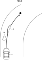
- FIG. 6 illustrates an example of a behavior of the vehicle 1 when slipping occurs.
- the solid line is an actual travel route of the vehicle 1
- a dotted line is a travel route set by the computation device 110 (hereinafter referred to as a theoretical travel route R).
- the solid line and the dotted line partially overlap each other.
- a black circle indicates a goal of the vehicle 1.
- supposing a puddle W is present in the middle of the travel route of the vehicle 1 and the front wheels of the vehicle 1 go into the puddle W to cause slipping.
- the vehicle 1 temporarily deviates from the theoretical travel route R. Slipping of the front wheels of the vehicle 1 is detected by the slipping sensor SW9 (see FIG. 5 ), and deviation from the theoretical travel route R is detected by the position sensor SW5 (see FIG. 5 ). These detection signals are input to the device controllers 200 to 500. Thereafter, for example, the brake microcomputer 300 actuates the brake actuator 33 so as to increase a braking force of the front wheels.
- the EPAS microcomputer 500 actuates the EPAS device 42 so as to cause the vehicle 1 to return to the theoretical travel route R.
- communication between the brake microcomputer 300 and the EPAS microcomputer 500 can optimize a controlled variable of the EPAS device 42 in consideration of a braking force by the braking device 30.
- the vehicle 1 can return to the theoretical travel route R smoothly and quickly so that traveling of the vehicle 1 can be stabilized.
- the device controllers 200 to 500 calculate controlled variables of the traveling device in order to eliminate or reduce the abnormality without using the computation device 110, and output control signals to the traveling devices. Accordingly, responsiveness of the traveling devices to vehicle outdoor environments can be enhanced.
- the vehicle travel control device includes: the computation device 110; and the device controllers 200 to 500 configured to control actuation of the traveling devices (e.g., the injector 12) mounted on the vehicle 1 based on a computation result of the computation device 110.
- the traveling devices e.g., the injector 12
- the computation device 110 includes: the vehicle outdoor environment identifier 111 configured to identify a vehicle outdoor environment based on outputs from the cameras 70 and the radars 71 configured to acquire information on the vehicle outdoor environment; the route setter (e.g., the route calculator 112) configured to set a route on which the vehicle 1 is to travel in accordance with the vehicle outdoor environment identified by the vehicle outdoor environment identifier 111; the vehicle motion determiner 116 configured to determine a target motion of the vehicle 1 in order to follow the route set by the route setter; and the physical quantity calculators 117 to 119 configured to calculate target physical quantities in order to achieve the target motion determined by the vehicle motion determiner 116.
- the route setter e.g., the route calculator 112
- the vehicle motion determiner 116 configured to determine a target motion of the vehicle 1 in order to follow the route set by the route setter
- the physical quantity calculators 117 to 119 configured to calculate target physical quantities in order to achieve the target motion determined by the vehicle motion determiner 116.
- the device controllers 200 to 500 calculate controlled variables of the traveling devices such that the target physical quantities calculated by the physical quantity calculators 117 to 119 is achieved, and outputs control signals to the traveling devices. In this manner, the computation device 110 only calculates physical quantities to be achieved, and actual controlled variables of the traveling devices are calculated by the device controllers 200 to 500. Accordingly, the amount of calculation of the computation device 110 decreases so that the calculation speed of the computation device 110 can be increased.
- the device controllers 200 to 500 only need to calculate actual controlled variables and output control signals to the traveling devices, and thus, processing speeds thereof are high. Consequently, responsiveness of the traveling devices to the vehicle outdoor environment can be increased.
- the vehicle outdoor environment identifier 111 identifies a vehicle outdoor environment by using deep learning, and thus, especially the computation device 110 performs a large amount of calculation.
- the controlled variables of the traveling devices are calculated by the device controllers 200 to 500 other than the computation device 110 so that the advantage of further enhancing responsiveness of the traveling devices to the vehicle outdoor environment can be more appropriately obtained.
- the driving force calculator 117, the braking force calculator 118, and the steering variable calculator 119 may change a target driving force, for example, in accordance with the state of a driver of the vehicle 1. For example, while the driver enjoys driving (e.g., feeling of the driver is "enjoy"), the target driving force, for example, may be reduced so that the driving state approaches manual driving as close as possible. On the other hand, if the driver is in a poor physical condition, the target driving force, for example, is increased so that the driving state approaches automated driving as close as possible.
- the route determiner 115 determines a route on which the vehicle 1 is to travel.
- the technique is not limited to this example, and the route determiner 115 may be omitted, and the vehicle motion determiner 116 may determine a route on which the vehicle 1 is to travel. That is, the vehicle motion determiner 116 may serve as both a part of the route setter and the target motion determiner.
- the driving force calculator 117, the braking force calculator 118, and the steering variable calculator 119 calculate target physical quantities such as a target driving force.
- the technique is not limited to this example, and the driving force calculator 117, the braking force calculator 118, and the steering variable calculator 119 may be omitted, and the vehicle motion determiner 116 may calculate a target physical quantity. That is, the vehicle motion determiner 116 may serve as both the target motion determiner and the physical quantity calculator.
- the technique disclosed here is useful as a vehicle travel control device for controlling traveling of a vehicle.
Landscapes
- Engineering & Computer Science (AREA)
- Mechanical Engineering (AREA)
- Transportation (AREA)
- Combustion & Propulsion (AREA)
- Chemical & Material Sciences (AREA)
- Automation & Control Theory (AREA)
- Physics & Mathematics (AREA)
- Theoretical Computer Science (AREA)
- Human Computer Interaction (AREA)
- Mathematical Physics (AREA)
- Biophysics (AREA)
- Computational Linguistics (AREA)
- Computing Systems (AREA)
- General Engineering & Computer Science (AREA)
- General Physics & Mathematics (AREA)
- General Health & Medical Sciences (AREA)
- Software Systems (AREA)
- Evolutionary Computation (AREA)
- Data Mining & Analysis (AREA)
- Molecular Biology (AREA)
- Biomedical Technology (AREA)
- Artificial Intelligence (AREA)
- Life Sciences & Earth Sciences (AREA)
- Health & Medical Sciences (AREA)
- Control Of Driving Devices And Active Controlling Of Vehicle (AREA)
- Steering Control In Accordance With Driving Conditions (AREA)
- Regulating Braking Force (AREA)
Claims (4)
- Dispositif de commande de déplacement de véhicule (100) configuré pour commander un déplacement d'un véhicule (1), le dispositif de commande de déplacement de véhicule (100) comprenant :un dispositif de calcul (110) ;une unité de commande de dispositif (200, 300, 500) configurée pour commander l'actionnement d'un dispositif de déplacement (12, 13, 16, 20, 33, 42) monté sur le véhicule (1), sur la base d'un résultat de calcul du dispositif de calcul (110) ; etun détecteur d'anomalie (SW5, SW6, SW7) configuré pour détecter une anomalie se produisant lors du déplacement du véhicule (1), dans lequelle dispositif de calcul (110) comporteune unité d'identification d'environnement extérieur au véhicule (111) configurée pour identifier un environnement extérieur au véhicule sur la base d'une sortie provenant de l'unité d'acquisition d'image, l'unité d'acquisition d'image étant configurée pour acquérir un environnement extérieur au véhicule,une unité de réglage d'itinéraire (112, 115) configurée pour régler un itinéraire sur lequel le véhicule (1) doit se déplacer, en fonction de l'environnement extérieur au véhicule identifié par l'unité d'identification d'environnement extérieur au véhicule (111),une unité de détermination de mouvement de véhicule (116) configurée pour déterminer un mouvement cible du véhicule (1) pour le suivi de l'itinéraire réglé par l'unité de réglage d'itinéraire (112, 115), etune unité de calcul de quantité physique (117, 118, 119) configurée pour calculer une quantité physique cible devant être générée par le dispositif de déplacement (12, 13, 16, 20, 33, 42), afin d'obtenir le mouvement cible déterminé par l'unité de détermination de mouvement cible (116),caractérisé en ce que le détecteur d'anomalie (SW5, SW6, SW7) est un capteur et entre un signal de détection dans l'unité de commande de dispositif (200, 300, 500) lors de la détection d'une anomalie,l'unité de commande de dispositif (200, 300, 500) calcule une variable commandée du dispositif de déplacement (12, 13, 16, 20, 33, 42) de sorte que la quantité physique cible calculée par l'unité de calcul de quantité physique (117, 118, 119) soit obtenue, et l'unité de commande de dispositif délivre en sortie un signal de commande au dispositif de déplacement (12, 13, 16, 20, 33, 42), etlorsqu'un signal de détection est entré à partir du détecteur d'anomalie (SW5, SW6, SW7) dans l'unité de commande de dispositif (200, 300, 500), l'unité de commande de dispositif (200, 300, 500) calcule une variable commandée du dispositif de déplacement (12, 13, 16, 20, 33, 42), en n'utilisant pas le dispositif de calcul (110), afin d'éliminer ou de réduire l'anomalie, et délivre en sortie un signal de commande au dispositif de déplacement (12, 13, 16, 20, 33, 42).
- Dispositif de commande de déplacement de véhicule selon la revendication 1, l'unité de réglage d'itinéraire (112, 115) comportantune unité de génération d'itinéraires candidats (112) configurée pour générer un ou plusieurs itinéraires candidats sur lesquels le véhicule (1) est apte à se déplacer, etune unité de détermination d'itinéraire (115) configurée pour déterminer un itinéraire sur lequel le véhicule (1) doit se déplacer à partir des itinéraires candidats générés par l'unité de génération d'itinéraires candidats (112).
- Dispositif de commande de déplacement de véhicule selon la revendication 1 ou 2, dans lequelle dispositif de déplacement comprend un dispositif associé au groupe motopropulseur (12, 13, 16, 20) constituant un dispositif de groupe motopropulseur, un dispositif associé au frein (33) constituant un dispositif de freinage, et un dispositif associé à la direction (42) constituant un dispositif de direction,l'unité de commande de dispositif (200, 300, 500) comprend une unité de commande de groupe motopropulseur (200) configurée pour commander l'actionnement du dispositif associé au groupe motopropulseur (12, 13, 16, 20), une unité de commande de frein (300) configurée pour commander l'actionnement du dispositif associé au frein (33), et une unité de commande de direction (500) configurée pour commander l'actionnement du dispositif associé à la direction (42), etl'unité de commande de groupe motopropulseur (200), l'unité de commande de frein (300), et l'unité de commande de direction (500) sont configurées pour être en communication entre elles, et partagent des informations sur une variable commandée calculée par l'unité de commande de groupe motopropulseur (200), l'unité de commande de frein (300), et l'unité de commande de direction (500).
- Dispositif de commande de déplacement de véhicule selon l'une quelconque des revendications 1 à 3, dans lequel
l'unité d'identification d'environnement extérieur au véhicule (111) identifie un environnement extérieur au véhicule au moyen d'un apprentissage profond.
Applications Claiming Priority (2)
| Application Number | Priority Date | Filing Date | Title |
|---|---|---|---|
| JP2019068276A JP7243392B2 (ja) | 2019-03-29 | 2019-03-29 | 車両走行制御装置 |
| PCT/JP2020/009784 WO2020203055A1 (fr) | 2019-03-29 | 2020-03-06 | Dispositif de commande de déplacement de véhicule |
Publications (3)
| Publication Number | Publication Date |
|---|---|
| EP3904186A1 EP3904186A1 (fr) | 2021-11-03 |
| EP3904186A4 EP3904186A4 (fr) | 2022-03-09 |
| EP3904186B1 true EP3904186B1 (fr) | 2025-06-04 |
Family
ID=72667718
Family Applications (1)
| Application Number | Title | Priority Date | Filing Date |
|---|---|---|---|
| EP20783611.5A Active EP3904186B1 (fr) | 2019-03-29 | 2020-03-06 | Dispositif de commande de déplacement de véhicule |
Country Status (5)
| Country | Link |
|---|---|
| US (1) | US11858523B2 (fr) |
| EP (1) | EP3904186B1 (fr) |
| JP (1) | JP7243392B2 (fr) |
| CN (1) | CN113597390B (fr) |
| WO (1) | WO2020203055A1 (fr) |
Families Citing this family (7)
| Publication number | Priority date | Publication date | Assignee | Title |
|---|---|---|---|---|
| JP7244643B2 (ja) * | 2019-06-21 | 2023-03-22 | 日立Astemo株式会社 | 車両制御装置 |
| US11807266B2 (en) * | 2020-12-04 | 2023-11-07 | Mitsubishi Electric Corporation | Driving system for distribution of planning and control functionality between vehicle device and cloud computing device, vehicle computing device, and cloud computing device |
| KR20230086437A (ko) | 2021-12-08 | 2023-06-15 | 현대모비스 주식회사 | 차량의 제동력 제어 장치 및 방법 |
| JP7722334B2 (ja) * | 2022-11-02 | 2025-08-13 | トヨタ自動車株式会社 | 車載システム |
| US12594914B2 (en) * | 2023-08-03 | 2026-04-07 | Steering Solutions Ip Holding Corporation | Brake-to-steer lateral stability management based on stability indicator correlation |
| US12600346B2 (en) | 2023-08-03 | 2026-04-14 | Steering Solutions Ip Holding Corporation | Brake-to-steer lateral stability management based on stability indicator correlation |
| US12539841B2 (en) | 2023-08-03 | 2026-02-03 | Steering Solutions IP Holding Corporation Continental Automotive Systems Inc | Brake-to-Steer lateral stability management based on stability indicator correlation |
Family Cites Families (19)
| Publication number | Priority date | Publication date | Assignee | Title |
|---|---|---|---|---|
| JP3203777B2 (ja) * | 1992-07-13 | 2001-08-27 | 株式会社デンソー | 車載用電源制御装置 |
| US9533539B2 (en) * | 2011-10-20 | 2017-01-03 | GM Global Technology Operations LLC | Vehicle suspension system and method of using the same |
| JP2014213628A (ja) * | 2013-04-23 | 2014-11-17 | 本田技研工業株式会社 | 車両の制動システム |
| JP6183257B2 (ja) * | 2014-03-19 | 2017-08-23 | トヨタ自動車株式会社 | 車両運動状態決定装置及び車両運動制御装置 |
| JP6322109B2 (ja) * | 2014-09-29 | 2018-05-09 | 株式会社Subaru | 車両の走行制御装置 |
| JP6561597B2 (ja) | 2015-06-02 | 2019-08-21 | 株式会社ジェイテクト | 車両用制御装置 |
| US10229231B2 (en) * | 2015-09-11 | 2019-03-12 | Ford Global Technologies, Llc | Sensor-data generation in virtual driving environment |
| JP6485306B2 (ja) | 2015-09-25 | 2019-03-20 | 株式会社デンソー | 制御システム |
| EP3159853B1 (fr) * | 2015-10-23 | 2019-03-27 | Harman International Industries, Incorporated | Systèmes et procédés d'analyse avancée d'assistance au conducteur |
| JP6698320B2 (ja) * | 2015-11-16 | 2020-05-27 | 日立オートモティブシステムズ株式会社 | 処理装置および車両制御システム |
| US9889716B2 (en) * | 2016-02-03 | 2018-02-13 | Ford Global Technologies, Llc | Roadway-crossing-anomaly detection system and method |
| JP2017182347A (ja) | 2016-03-29 | 2017-10-05 | 株式会社オートネットワーク技術研究所 | 車両用通信システム、車両周辺情報送信方法及び制御プログラム |
| JP6728921B2 (ja) * | 2016-04-15 | 2020-07-22 | いすゞ自動車株式会社 | 運転支援装置 |
| WO2018134901A1 (fr) | 2017-01-18 | 2018-07-26 | 本田技研工業株式会社 | Dispositif de commande de véhicule |
| JP6895111B2 (ja) | 2017-03-23 | 2021-06-30 | スズキ株式会社 | 車両の走行制御装置 |
| JP6638695B2 (ja) * | 2017-05-18 | 2020-01-29 | トヨタ自動車株式会社 | 自動運転システム |
| JP6525402B2 (ja) * | 2017-08-30 | 2019-06-05 | マツダ株式会社 | 車両制御装置 |
| JP7232100B2 (ja) * | 2019-03-28 | 2023-03-02 | 株式会社Subaru | 車両の走行制御装置 |
| US11568687B2 (en) * | 2019-10-31 | 2023-01-31 | Pony Ai Inc. | Automated vehicular damage detection |
-
2019
- 2019-03-29 JP JP2019068276A patent/JP7243392B2/ja active Active
-
2020
- 2020-03-06 CN CN202080012708.2A patent/CN113597390B/zh active Active
- 2020-03-06 WO PCT/JP2020/009784 patent/WO2020203055A1/fr not_active Ceased
- 2020-03-06 EP EP20783611.5A patent/EP3904186B1/fr active Active
-
2021
- 2021-09-24 US US17/483,841 patent/US11858523B2/en active Active
Also Published As
| Publication number | Publication date |
|---|---|
| EP3904186A4 (fr) | 2022-03-09 |
| WO2020203055A1 (fr) | 2020-10-08 |
| US20220009509A1 (en) | 2022-01-13 |
| EP3904186A1 (fr) | 2021-11-03 |
| JP2020164103A (ja) | 2020-10-08 |
| US11858523B2 (en) | 2024-01-02 |
| CN113597390A (zh) | 2021-11-02 |
| JP7243392B2 (ja) | 2023-03-22 |
| CN113597390B (zh) | 2024-01-26 |
Similar Documents
| Publication | Publication Date | Title |
|---|---|---|
| EP3904186B1 (fr) | Dispositif de commande de déplacement de véhicule | |
| EP3936403B1 (fr) | Système de commande de déplacement pour véhicule | |
| EP3907116A1 (fr) | Appareil de commande de déplacement de véhicule | |
| EP3900993A1 (fr) | Dispositif de commande de déplacement de véhicule | |
| US11952000B2 (en) | Vehicle failure diagnostic device | |
| EP3925842B1 (fr) | Système de commande de déplacement | |
| US20220332333A1 (en) | On-board network system | |
| EP3909824B1 (fr) | Appareil de commande de déplacement de véhicule | |
| US20220321656A1 (en) | In-vehicle network system | |
| EP4094969B1 (fr) | Appareil de commande de véhicule, véhicule et procédé de commande de véhicule |
Legal Events
| Date | Code | Title | Description |
|---|---|---|---|
| STAA | Information on the status of an ep patent application or granted ep patent |
Free format text: STATUS: THE INTERNATIONAL PUBLICATION HAS BEEN MADE |
|
| PUAI | Public reference made under article 153(3) epc to a published international application that has entered the european phase |
Free format text: ORIGINAL CODE: 0009012 |
|
| STAA | Information on the status of an ep patent application or granted ep patent |
Free format text: STATUS: REQUEST FOR EXAMINATION WAS MADE |
|
| 17P | Request for examination filed |
Effective date: 20210726 |
|
| AK | Designated contracting states |
Kind code of ref document: A1 Designated state(s): AL AT BE BG CH CY CZ DE DK EE ES FI FR GB GR HR HU IE IS IT LI LT LU LV MC MK MT NL NO PL PT RO RS SE SI SK SM TR |
|
| A4 | Supplementary search report drawn up and despatched |
Effective date: 20220207 |
|
| RIC1 | Information provided on ipc code assigned before grant |
Ipc: B60W 60/00 20200101ALI20220202BHEP Ipc: B60W 30/18 20120101ALI20220202BHEP Ipc: B60W 50/035 20120101ALI20220202BHEP Ipc: B60W 30/10 20060101ALI20220202BHEP Ipc: B60W 30/02 20120101ALI20220202BHEP Ipc: B62D 6/00 20060101ALI20220202BHEP Ipc: B60T 7/12 20060101ALI20220202BHEP Ipc: B62D 137/00 20060101ALI20220202BHEP Ipc: B62D 113/00 20060101ALI20220202BHEP Ipc: B62D 111/00 20060101ALI20220202BHEP Ipc: B62D 103/00 20060101ALI20220202BHEP Ipc: B62D 101/00 20060101AFI20220202BHEP |
|
| DAV | Request for validation of the european patent (deleted) | ||
| DAX | Request for extension of the european patent (deleted) | ||
| STAA | Information on the status of an ep patent application or granted ep patent |
Free format text: STATUS: EXAMINATION IS IN PROGRESS |
|
| 17Q | First examination report despatched |
Effective date: 20231115 |
|
| GRAP | Despatch of communication of intention to grant a patent |
Free format text: ORIGINAL CODE: EPIDOSNIGR1 |
|
| STAA | Information on the status of an ep patent application or granted ep patent |
Free format text: STATUS: GRANT OF PATENT IS INTENDED |
|
| INTG | Intention to grant announced |
Effective date: 20250227 |
|
| GRAS | Grant fee paid |
Free format text: ORIGINAL CODE: EPIDOSNIGR3 |
|
| GRAA | (expected) grant |
Free format text: ORIGINAL CODE: 0009210 |
|
| STAA | Information on the status of an ep patent application or granted ep patent |
Free format text: STATUS: THE PATENT HAS BEEN GRANTED |
|
| AK | Designated contracting states |
Kind code of ref document: B1 Designated state(s): AL AT BE BG CH CY CZ DE DK EE ES FI FR GB GR HR HU IE IS IT LI LT LU LV MC MK MT NL NO PL PT RO RS SE SI SK SM TR |
|
| REG | Reference to a national code |
Ref country code: GB Ref legal event code: FG4D |
|
| REG | Reference to a national code |
Ref country code: CH Ref legal event code: EP |
|
| REG | Reference to a national code |
Ref country code: DE Ref legal event code: R096 Ref document number: 602020052329 Country of ref document: DE |
|
| REG | Reference to a national code |
Ref country code: IE Ref legal event code: FG4D |
|
| REG | Reference to a national code |
Ref country code: NL Ref legal event code: MP Effective date: 20250604 |
|
| PG25 | Lapsed in a contracting state [announced via postgrant information from national office to epo] |
Ref country code: FI Free format text: LAPSE BECAUSE OF FAILURE TO SUBMIT A TRANSLATION OF THE DESCRIPTION OR TO PAY THE FEE WITHIN THE PRESCRIBED TIME-LIMIT Effective date: 20250604 Ref country code: ES Free format text: LAPSE BECAUSE OF FAILURE TO SUBMIT A TRANSLATION OF THE DESCRIPTION OR TO PAY THE FEE WITHIN THE PRESCRIBED TIME-LIMIT Effective date: 20250604 |
|
| REG | Reference to a national code |
Ref country code: LT Ref legal event code: MG9D |
|
| PG25 | Lapsed in a contracting state [announced via postgrant information from national office to epo] |
Ref country code: GR Free format text: LAPSE BECAUSE OF FAILURE TO SUBMIT A TRANSLATION OF THE DESCRIPTION OR TO PAY THE FEE WITHIN THE PRESCRIBED TIME-LIMIT Effective date: 20250905 Ref country code: NO Free format text: LAPSE BECAUSE OF FAILURE TO SUBMIT A TRANSLATION OF THE DESCRIPTION OR TO PAY THE FEE WITHIN THE PRESCRIBED TIME-LIMIT Effective date: 20250904 |
|
| PG25 | Lapsed in a contracting state [announced via postgrant information from national office to epo] |
Ref country code: PL Free format text: LAPSE BECAUSE OF FAILURE TO SUBMIT A TRANSLATION OF THE DESCRIPTION OR TO PAY THE FEE WITHIN THE PRESCRIBED TIME-LIMIT Effective date: 20250604 |
|
| PG25 | Lapsed in a contracting state [announced via postgrant information from national office to epo] |
Ref country code: BG Free format text: LAPSE BECAUSE OF FAILURE TO SUBMIT A TRANSLATION OF THE DESCRIPTION OR TO PAY THE FEE WITHIN THE PRESCRIBED TIME-LIMIT Effective date: 20250604 |
|
| PG25 | Lapsed in a contracting state [announced via postgrant information from national office to epo] |
Ref country code: HR Free format text: LAPSE BECAUSE OF FAILURE TO SUBMIT A TRANSLATION OF THE DESCRIPTION OR TO PAY THE FEE WITHIN THE PRESCRIBED TIME-LIMIT Effective date: 20250604 |
|
| PG25 | Lapsed in a contracting state [announced via postgrant information from national office to epo] |
Ref country code: RS Free format text: LAPSE BECAUSE OF FAILURE TO SUBMIT A TRANSLATION OF THE DESCRIPTION OR TO PAY THE FEE WITHIN THE PRESCRIBED TIME-LIMIT Effective date: 20250904 |
|
| PG25 | Lapsed in a contracting state [announced via postgrant information from national office to epo] |
Ref country code: LV Free format text: LAPSE BECAUSE OF FAILURE TO SUBMIT A TRANSLATION OF THE DESCRIPTION OR TO PAY THE FEE WITHIN THE PRESCRIBED TIME-LIMIT Effective date: 20250604 |
|
| PG25 | Lapsed in a contracting state [announced via postgrant information from national office to epo] |
Ref country code: NL Free format text: LAPSE BECAUSE OF FAILURE TO SUBMIT A TRANSLATION OF THE DESCRIPTION OR TO PAY THE FEE WITHIN THE PRESCRIBED TIME-LIMIT Effective date: 20250604 |
|
| PG25 | Lapsed in a contracting state [announced via postgrant information from national office to epo] |
Ref country code: PT Free format text: LAPSE BECAUSE OF FAILURE TO SUBMIT A TRANSLATION OF THE DESCRIPTION OR TO PAY THE FEE WITHIN THE PRESCRIBED TIME-LIMIT Effective date: 20251006 |
|
| REG | Reference to a national code |
Ref country code: AT Ref legal event code: MK05 Ref document number: 1800115 Country of ref document: AT Kind code of ref document: T Effective date: 20250604 |
|
| PG25 | Lapsed in a contracting state [announced via postgrant information from national office to epo] |
Ref country code: IS Free format text: LAPSE BECAUSE OF FAILURE TO SUBMIT A TRANSLATION OF THE DESCRIPTION OR TO PAY THE FEE WITHIN THE PRESCRIBED TIME-LIMIT Effective date: 20251004 |
|
| PG25 | Lapsed in a contracting state [announced via postgrant information from national office to epo] |
Ref country code: SM Free format text: LAPSE BECAUSE OF FAILURE TO SUBMIT A TRANSLATION OF THE DESCRIPTION OR TO PAY THE FEE WITHIN THE PRESCRIBED TIME-LIMIT Effective date: 20250604 Ref country code: AT Free format text: LAPSE BECAUSE OF FAILURE TO SUBMIT A TRANSLATION OF THE DESCRIPTION OR TO PAY THE FEE WITHIN THE PRESCRIBED TIME-LIMIT Effective date: 20250604 |
|
| PG25 | Lapsed in a contracting state [announced via postgrant information from national office to epo] |
Ref country code: CZ Free format text: LAPSE BECAUSE OF FAILURE TO SUBMIT A TRANSLATION OF THE DESCRIPTION OR TO PAY THE FEE WITHIN THE PRESCRIBED TIME-LIMIT Effective date: 20250604 |
|
| PG25 | Lapsed in a contracting state [announced via postgrant information from national office to epo] |
Ref country code: EE Free format text: LAPSE BECAUSE OF FAILURE TO SUBMIT A TRANSLATION OF THE DESCRIPTION OR TO PAY THE FEE WITHIN THE PRESCRIBED TIME-LIMIT Effective date: 20250604 |
|
| PG25 | Lapsed in a contracting state [announced via postgrant information from national office to epo] |
Ref country code: SK Free format text: LAPSE BECAUSE OF FAILURE TO SUBMIT A TRANSLATION OF THE DESCRIPTION OR TO PAY THE FEE WITHIN THE PRESCRIBED TIME-LIMIT Effective date: 20250604 Ref country code: RO Free format text: LAPSE BECAUSE OF FAILURE TO SUBMIT A TRANSLATION OF THE DESCRIPTION OR TO PAY THE FEE WITHIN THE PRESCRIBED TIME-LIMIT Effective date: 20250604 |
|
| PG25 | Lapsed in a contracting state [announced via postgrant information from national office to epo] |
Ref country code: IT Free format text: LAPSE BECAUSE OF FAILURE TO SUBMIT A TRANSLATION OF THE DESCRIPTION OR TO PAY THE FEE WITHIN THE PRESCRIBED TIME-LIMIT Effective date: 20250604 |
|
| REG | Reference to a national code |
Ref country code: DE Ref legal event code: R097 Ref document number: 602020052329 Country of ref document: DE |
|
| PLBE | No opposition filed within time limit |
Free format text: ORIGINAL CODE: 0009261 |
|
| STAA | Information on the status of an ep patent application or granted ep patent |
Free format text: STATUS: NO OPPOSITION FILED WITHIN TIME LIMIT |
|
| PG25 | Lapsed in a contracting state [announced via postgrant information from national office to epo] |
Ref country code: DK Free format text: LAPSE BECAUSE OF FAILURE TO SUBMIT A TRANSLATION OF THE DESCRIPTION OR TO PAY THE FEE WITHIN THE PRESCRIBED TIME-LIMIT Effective date: 20250604 |
|
| PGFP | Annual fee paid to national office [announced via postgrant information from national office to epo] |
Ref country code: DE Payment date: 20260128 Year of fee payment: 7 |
|
| REG | Reference to a national code |
Ref country code: CH Ref legal event code: L10 Free format text: ST27 STATUS EVENT CODE: U-0-0-L10-L00 (AS PROVIDED BY THE NATIONAL OFFICE) Effective date: 20260416 |