EP3904193B1 - Dispositif de positionnement sélectif de pivot d'une roue - Google Patents
Dispositif de positionnement sélectif de pivot d'une roue Download PDFInfo
- Publication number
- EP3904193B1 EP3904193B1 EP21167865.1A EP21167865A EP3904193B1 EP 3904193 B1 EP3904193 B1 EP 3904193B1 EP 21167865 A EP21167865 A EP 21167865A EP 3904193 B1 EP3904193 B1 EP 3904193B1
- Authority
- EP
- European Patent Office
- Prior art keywords
- adapter
- internal
- bicycle frame
- hole
- seat
- Prior art date
- Legal status (The legal status is an assumption and is not a legal conclusion. Google has not performed a legal analysis and makes no representation as to the accuracy of the status listed.)
- Active
Links
Images




Classifications
-
- B—PERFORMING OPERATIONS; TRANSPORTING
- B62—LAND VEHICLES FOR TRAVELLING OTHERWISE THAN ON RAILS
- B62K—CYCLES; CYCLE FRAMES; CYCLE STEERING DEVICES; RIDER-OPERATED TERMINAL CONTROLS SPECIALLY ADAPTED FOR CYCLES; CYCLE AXLE SUSPENSIONS; CYCLE SIDECARS, FORECARS, OR THE LIKE
- B62K25/00—Axle suspensions
- B62K25/02—Axle suspensions for mounting axles rigidly on cycle frame or fork, e.g. adjustably
-
- B—PERFORMING OPERATIONS; TRANSPORTING
- B62—LAND VEHICLES FOR TRAVELLING OTHERWISE THAN ON RAILS
- B62K—CYCLES; CYCLE FRAMES; CYCLE STEERING DEVICES; RIDER-OPERATED TERMINAL CONTROLS SPECIALLY ADAPTED FOR CYCLES; CYCLE AXLE SUSPENSIONS; CYCLE SIDECARS, FORECARS, OR THE LIKE
- B62K25/00—Axle suspensions
- B62K25/04—Axle suspensions for mounting axles resiliently on cycle frame or fork
- B62K25/28—Axle suspensions for mounting axles resiliently on cycle frame or fork with pivoted chain-stay
-
- B—PERFORMING OPERATIONS; TRANSPORTING
- B62—LAND VEHICLES FOR TRAVELLING OTHERWISE THAN ON RAILS
- B62K—CYCLES; CYCLE FRAMES; CYCLE STEERING DEVICES; RIDER-OPERATED TERMINAL CONTROLS SPECIALLY ADAPTED FOR CYCLES; CYCLE AXLE SUSPENSIONS; CYCLE SIDECARS, FORECARS, OR THE LIKE
- B62K25/00—Axle suspensions
- B62K25/04—Axle suspensions for mounting axles resiliently on cycle frame or fork
- B62K25/28—Axle suspensions for mounting axles resiliently on cycle frame or fork with pivoted chain-stay
- B62K25/286—Axle suspensions for mounting axles resiliently on cycle frame or fork with pivoted chain-stay the shock absorber being connected to the chain-stay via a linkage mechanism
-
- B—PERFORMING OPERATIONS; TRANSPORTING
- B62—LAND VEHICLES FOR TRAVELLING OTHERWISE THAN ON RAILS
- B62M—RIDER PROPULSION OF WHEELED VEHICLES OR SLEDGES; POWERED PROPULSION OF SLEDGES OR SINGLE-TRACK CYCLES; TRANSMISSIONS SPECIALLY ADAPTED FOR SUCH VEHICLES
- B62M9/00—Transmissions characterised by use of an endless chain, belt, or the like
- B62M9/04—Transmissions characterised by use of an endless chain, belt, or the like of changeable ratio
- B62M9/06—Transmissions characterised by use of an endless chain, belt, or the like of changeable ratio using a single chain, belt, or the like
- B62M9/10—Transmissions characterised by use of an endless chain, belt, or the like of changeable ratio using a single chain, belt, or the like involving different-sized wheels, e.g. rear sprocket chain wheels selectively engaged by the chain, belt, or the like
- B62M9/12—Transmissions characterised by use of an endless chain, belt, or the like of changeable ratio using a single chain, belt, or the like involving different-sized wheels, e.g. rear sprocket chain wheels selectively engaged by the chain, belt, or the like the chain, belt, or the like being laterally shiftable, e.g. using a rear derailleur
- B62M9/121—Rear derailleurs
- B62M9/125—Mounting the derailleur on the frame
-
- B—PERFORMING OPERATIONS; TRANSPORTING
- B62—LAND VEHICLES FOR TRAVELLING OTHERWISE THAN ON RAILS
- B62K—CYCLES; CYCLE FRAMES; CYCLE STEERING DEVICES; RIDER-OPERATED TERMINAL CONTROLS SPECIALLY ADAPTED FOR CYCLES; CYCLE AXLE SUSPENSIONS; CYCLE SIDECARS, FORECARS, OR THE LIKE
- B62K25/00—Axle suspensions
- B62K25/04—Axle suspensions for mounting axles resiliently on cycle frame or fork
- B62K2025/047—Axle suspensions for mounting axles resiliently on cycle frame or fork with suspension locking means
-
- B—PERFORMING OPERATIONS; TRANSPORTING
- B62—LAND VEHICLES FOR TRAVELLING OTHERWISE THAN ON RAILS
- B62K—CYCLES; CYCLE FRAMES; CYCLE STEERING DEVICES; RIDER-OPERATED TERMINAL CONTROLS SPECIALLY ADAPTED FOR CYCLES; CYCLE AXLE SUSPENSIONS; CYCLE SIDECARS, FORECARS, OR THE LIKE
- B62K25/00—Axle suspensions
- B62K25/04—Axle suspensions for mounting axles resiliently on cycle frame or fork
- B62K25/28—Axle suspensions for mounting axles resiliently on cycle frame or fork with pivoted chain-stay
- B62K25/30—Axle suspensions for mounting axles resiliently on cycle frame or fork with pivoted chain-stay pivoted on pedal crank shelf
Definitions
- the present invention relates to a device for the selective positioning of the pivot of a wheel, particularly for bicycles, particularly but not exclusively of the pedal-assist type, for example for city use.
- Bikes or bicycles of the known type are usually constituted by a frame composed of various tubular elements so as to obtain a structure composed of a top tube connected at one end to a head tube and at the other end to a rear vertical tube and to a saddle post.
- Two oblique rear chainstays or dropouts are usually connected at the connection of the saddle post and/or of the top tube and/or of the vertical tube, while horizontal rear chainstays or dropouts are connected at the connection of the downtube and of the vertical tube, are connected at their ends to the two oblique rear chainstays or dropouts and have a seat for an axle of a wheel.
- a brake caliper can be connected to the chainstays or dropouts.
- wheel fixing systems which are of the type comprising a quick coupling which is fixed to the ends of the hub of the wheel, said hub ends being insertable at adapted seats provided at the ends of the chainstays or dropouts.
- the dimensions and shape of the chainstays or dropouts are designed to receive a wheel axle or wheels of given dimensions, various choices for example of wheels from 27.5" to 29", being commercially available, these dimensions being correlated to the diameter of the rim, which in the case of 29" wheels is 622 mm or 28 inches.
- a bicycle of the known type for example designed for 27.5" wheels, is not compatible with 29" wheels.
- FR3046400B1 discloses a solution related to a rear stay of a bicycle which comprises a frame and a rear dropout which supports the axle of the hub of a wheel and one end of which comprises, on the external surface, a seat for first adapter that is shaped complementarily, the adapter having an eccentric threaded hole adapted to receive the thread of the axle of the hub of the rear wheel so that the position of the threaded hole can be modified by positioning the first adapter in one direction or in the other direction in the seat in order to adapt the position of the hole as a function of the height of the side wall of the wheel.
- Two screws are provided which are adapted to be positioned on adapted holes provided in the seat of the first adapter in order to allow the fixing of the latter to the dropout.
- a second adapter provided with an eccentric through hole, also capable of receiving the axle of the hub of the wheel, provided on the other dropout of the rear stay.
- the eccentricity of the threaded hole of the first adapter corresponds to the eccentricity of the through hole provided in the second adapter.
- Two adapted screws are also present in order to allow the fixing of the second adapter to the corresponding dropout.
- US 2019/0322333 is also known which discloses a derailleur hook in which there is a brake element configured for installation on an axial internal side of a portion of an associated bracket of a bicycle frame in order to install a rear gearshift mechanism of a derailleur system on the bicycle frame.
- the brake element can include a first portion, which has an opening or an opening assigned to the axis and which, in the installed state, is subject to a fastening force that acts between the rear bracket portion.
- the brake element can also include a second portion which has an installation opening that is radially offset with respect to the opening or opening in the installed state with respect to the axis and to which it is possible to fix one end of a coupling of a base element of the mechanism of the rear gearshift.
- connection of the derailleur hook to the chainstays occurs by means of a rotatable coupling between the derailleur hook itself and the through pivot of the wheel.
- the aim of the present invention is therefore to overcome the described technical problems, eliminating the drawbacks of the cited background art and thus devising a device for the positioning of a pivot of a wheel that allows to achieve rapidly and simply the installation on the rear stay of a bicycle of wheels of a different diameter despite the presence of a derailleur hook.
- an object of the invention is to allow the cyclist to be able to modify rapidly and simply in particular the position of the axis of the wheel in passing from 27.5" to 29".
- Another object of the invention is to devise a device for the selective positioning of the axis of a wheel allows quick and easy wheel changing in a bicycle and at the same time is provided in a small number of parts, is mechanically and constructively simple and strong, has low manufacturing and assembly costs, and does not require to be provided with specific fixing holes on the chainstays or dropouts.
- Another object of the invention is to devise a device that has high reliability and safety and at the same time has a small overall weight.
- Another object is to provide a device that can be disassembled and reassembled rapidly and easily even by personnel that is not particularly trained.
- Another object is to provide a device that combines with the preceding characteristics that of being used in a frame of a bicycle with a derailleur hook applied thereto that is simple, has low costs for its provision and the application of which allows, in case of impact of the derailleur against an object during racing, to rotate through a certain free arc and thus avoid breakage.
- a device for the selective positioning of the pivot of a wheel of a bicycle comprising a frame composed of a rear stay provided with a first pair of first oblique rear chainstays which are each connected, respectively by means of a triangular support, to a second pair of two second horizontal rear chainstays, a derailleur hook being associable with said first chainstays and second chainstays, characterized in that first external seats and second internal seats are provided at the first internal surface and at the first external surface of said support for the axial and removable positioning respectively of a first external adapter and of a second internal adapter and have respectively a second hole and a third hole, both of which are smooth and are adapted to determine two different axial arrangements of said derailleur hook and consequently of said pivot of said wheel with respect to said two first and second chainstays and are adapted to keep said derailleur hook locked in clockwise rotation and free to rotate counterclockwise only through a chosen arc.
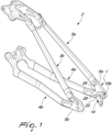
- the reference numeral 1 designates a device for the selective positioning of the pivot 100 of a wheel (not shown) of a bicycle (not shown), of the electric type or not, comprising a frame which is constituted by a rear stay 2 which comprises two first oblique rear chainstays or dropouts 3a, 3b (3a being also referenced as right and 3b as left) and two second horizontal rear chainstays or dropouts 4a, 4b (4a being also referenced as right and 4b as left), which are mutually connected at the ends by a triangular support 5a, 5b.
- Such first and second chainstays or dropouts 3a, 3b, 4a, 4b have, at the corner of the triangular supports 5a (also referenced as right), 5b (also referenced as left), a first hole 6a, 6b which has a figure-of-eight shape; the first hole 6a forms two circles 106a, 106b, which are contiguous, mutually identical and partially mutually intersect, both have smooth internal surfaces, and in turn determine two different conditions for the arrangement of a derailleur hook 14 (described hereinafter) and consequently of the pivot 100 of the wheel.
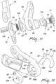
- a first external seat 8 and a second internal seat 9 are provided at the first external surface 7a and at the first internal surface 7b of said support 5a, which is connected to the first right chainstay 3a and to the second right chainstay 4a, for the axial and removable positioning respectively of a first external adapter 10a and of a second internal adapter 10b.
- the first external adapter 10a has a first head 11a having a substantially elliptical plan shape which is provided with a second hole 12, which is not threaded and eccentric, with a diameter that is substantially equal to the diameter of the sleeve 13 of the derailleur hook 14 of the known type, which can be traced back for example to US 2019/0322333 or to the UDH model of the company SRAM DEUTSCHLAND GmbH, such second hole 12 having a diameter that is substantially equal to the diameter of one of the circles 106a and 106b.
- a first stem 15 protrudes on the side of the first head 11a that is opposite the side on which the second hole 12 is provided, is therefore axially offset with respect to the second hole 12 and is shaped so that it can be inserted selectively in one of the two circles 106a and 106b following a 180° rotation of said first external adapter 10a.
- a cap or cover 16 also contributes to constitute the derailleur hook 14 and comprises a second head 17, which has a diameter equal to or greater than that of the second hole 12, from which a second stem 18 protrudes axially which has an external thread 19 that is threaded complementarily to the second internal thread 21 of the sleeve 13 and a first internal thread 20 which is threaded complementarily to the terminal end of the pivot 100 of the wheel.
- the second internal seat 9 has a substantially scalene trapezoid shape with a longer parallel side 24 which follows the shape of the lower side of the support 5a, a shorter parallel side 25 which has, from the corner of the support 5a toward the second chainstay 4a, a given inclination toward the underlying longer parallel side 24 and an oblique side 26 for connection between the longer parallel side 24 and the shorter parallel side 25 that is directed toward the second chainstay 4a.
- the second internal adapter 10b is constituted by a plate 22 which is shaped complementarily to the second internal seat 9, is substantially planar and is provided with a third hole 23, which is not threaded and is eccentric and has a diameter that is substantially equal to the diameter of the sleeve 13 and to the diameter of one of the circles 106a and 106b.
- a raised portion 27 shaped like a parallelepiped furthermore protrudes from the plate 22, parallel to the oblique side 26 and so as to partially affect the shorter parallel side 25, and in turn a pin 28 protrudes from the raised portion substantially adjacent to the connection between the oblique side 26 and the shorter parallel side 25 and is adapted to keep the derailleur hook 14, once mounted, locked in the direction of a clockwise rotation and free to rotate counterclockwise only through a chosen arc.
- the pin 28 in fact must act as abutment for the front arm 29 of the derailleur hook 14 if the latter is imparted a counterclockwise rotation, the pin 28 being arranged at a given, chosen and precise distance from the axis of the pivot 100 of the chosen wheel.
- the second internal adapter 10b is arranged differently with respect to the first internal seat 9 and at the same time the pin 28 moves, both axially and radially with respect to the first hole 6a, so as to maintain a precise distance from the axis of the pivot 100 of the wheel and allow the abutment therewith of the front arm 29 of the derailleur hook 14 upon a counterclockwise rotation.
- This second internal adapter 10b therefore moves together with the axis of the pivot 100 of the wheel so as to always have the front arm 29 of the derailleur hook 14 at the correct distance in order to prevent a counterclockwise rotation.
- a third external seat 31 and a fourth internal seat 32 for the axial and removable positioning respectively of a third external adapter 33a and of a fourth internal adapter 33b are provided at the second external surface 30a and at the second internal surface 30b of the support 5b, connected to the first left chainstay 3b and to the second left chainstay 4b.
- the fourth internal adapter 33b has a substantially C-shaped configuration so as to form, in the external perimetric connection region of wings 34a, 34b, a substantially planar portion 35 which is connected, in the direction of the second chainstay 4b, by a tooth 36 that protrudes toward the first chainstay 3b.
- the fourth internal seat 32 accommodates inside it the fourth internal adapter 33b and has, in the direction of the first chainstay 3b, a fifth seat 38 that is adapted to accommodate temporarily the complementarily shaped tooth 36; a sixth seat 39 is present and adjacent to the fifth seat 38, is similar to the preceding one and allows the selective positioning of the tooth 36 which makes the fourth internal adapter 33b translate in the direction of the second chainstay 4b.
- An interspace is formed between the wings 34a, 34b of the fourth internal adapter 33b and allows, regardless of the position assumed by the fourth internal adapter 33b, to not occlude the first hole 6b which also has a figure-of-eight shape so as to form two contiguous and partially intersecting circles 106c, 106d, which are mutually identical and both have smooth internal surfaces, which in turn determine two different conditions for the positioning of the pivot 100 of the wheel.
- the third adapter 33a has a triangular shape with rounded corners and can be inserted detachably in the third external seat 31.
- One corner of the third adapter 33a is directed toward the first chainstay 3b and a fourth hole 40 is provided thereon and accommodates a screw 41 for its temporary insertion at a fifth through hole 42 provided in the fourth internal seat 32 in a region below the fifth seat 38 for the tooth 36.
- the screw 41 is screwed onto a complementarily threaded sixth hole 43 provided in the fourth internal adapter 33b in a region below the fifth seat 38 when the tooth 36 is inserted in said fifth seat 38.
- the sixth hole 43 By moving the fourth internal adapter 33b so that the tooth 36 is arranged in the sixth seat 39, the sixth hole 43 also consequently moves at the same time; the screw 41 is thus fixed to a complementarily threaded seventh hole 44 provided in a region below the portion 35.
- the third external adapter 33a is provided with an eighth hole 45, which is axially offset with respect to the intersection point of the heights, which is arranged either in axial alignment with the circle 106c or in axial alignment with the circle 106d.
- the circles 106a, 106b and 106c, 106d are in fact respectively mutually axially aligned so that once the positioning of the first external adapter 10a and of the second internal adapter 10b has been defined, the third external adapter 33a is also positioned so that the pivot 100 of the wheel is in axial alignment either with the circles 106a, 106c or with the circles 106b, 106d.
- the changing of the wheel to be mounted for example passing from 27.5" wheels to 29" wheels, can be obtained by the cyclist without particular tools or instruments and rapidly and simply.
- first external adapter 10a and the second internal adapter 10b have said second hole 12 and said third hole 23 which are not threaded, thus allowing the free passage of the pivot 100 of the wheel, the pivot being fixed to the derailleur hook 14 by means of the cap or cover 16.
- the device is compatible with a derailleur hook of the known type, even if it is of the UDH model of the company SRAM DEUTSCHLAND GmbH, which requires an abutment in the internal part of the frame, at a very precise distance with respect to the wheel axis.
- the presence of the third external adapter 33a and of the fourth internal adapter 33b also allow to determine two different axial positions of the pivot 100 of the wheel with respect to the two first and second chainstays 3a, 3b, 4a, 4b, requiring a single screw for their mutual fixing.
- the rotatable application of the derailleur allows, in case of impact of the derailleur against an object during the race, to rotate through a certain free arc and thus avoid breakage.
Landscapes
- Engineering & Computer Science (AREA)
- Mechanical Engineering (AREA)
- Chemical & Material Sciences (AREA)
- Combustion & Propulsion (AREA)
- Transportation (AREA)
- Axle Suspensions And Sidecars For Cycles (AREA)
Claims (12)
- Dispositif (1) pour le positionnement sélectif de l'axe (100) d'une roue d'une bicyclette comprenant un cadre composé d'un triangle arrière (2) pourvu d'une première paire de premiers haubans obliques (3a, 3b) qui sont reliés chacun, respectivement au moyen d'un support triangulaire (5a, 5b), à une deuxième paire de deuxièmes bases horizontales (4a, 4b), une patte de dérailleur (14) pouvant être associée à l'un desdits premiers haubans (3a) et l'une desdites deuxièmes bases (4a) sur un premier côté du cadre de bicyclette, dans lequel des premiers sièges extérieurs (8) et des deuxièmes sièges intérieurs (9) sont prévus sur la première surface intérieure (7b) et sur la première surface extérieure (7a) du support triangulaire (5a) sur ledit premier côté du cadre pour le positionnement axial et amovible respectivement d'un premier adaptateur extérieur (10a) et d'un deuxième adaptateur intérieur (10b), dans lequel ledit premier adaptateur extérieur (10a) et ledit deuxième adaptateur intérieur (10b) ont respectivement un deuxième trou (12) et un troisième trou (23), tous deux étant lisses et adaptés pour déterminer deux agencements axiaux différents de ladite patte de dérailleur (14) et par conséquent dudit axe (100) de ladite roue par rapport auxdits deux premiers hauban et base (3a, 4a),
caractérisé en ce que ledit dispositif est adapté pour maintenir ladite patte de dérailleur (14) bloquée dans le sens des aiguilles d'une montre et libre de tourner dans le sens inverse des aiguilles d'une montre sur un arc choisi. - Dispositif (1) selon la revendication 1, caractérisé en ce que la base desdites deuxièmes bases (4b) située sur un deuxième côté du cadre de bicyclette opposé audit premier côté (4b) est connectée par un support triangulaire respectif (5b) sur une deuxième surface intérieure (30b) et sur une deuxième surface extérieure (30a) duquel se trouvent des troisièmes sièges extérieurs (31) et quatrièmes sièges intérieurs (32) pour le positionnement amovible, respectivement, d'un troisième adaptateur extérieur (33b) et d'un quatrième adaptateur intérieur (33a), qui sont adaptés pour déterminer deux agencements axiaux différents de ladite roue par rapport auxdits deux premiers haubans et deuxième bases (3a, 3b, 4a, 4b).
- Dispositif (1) selon l'une ou plusieurs des revendications précédentes, caractérisé en ce que lesdits premiers haubans et deuxième bases ou pattes (3a, 3b, 4a, 4b) ont, au sommet desdits supports triangulaires (5a, 5b), un premier trou (6a, 6b) qui a la forme d'un chiffre huit, ledit premier trou (6a, 6b) formant deux cercles (106a, 106b, 106c, 106d) qui sont contigus, mutuellement identiques et qui se coupent partiellement entre eux et tous deux ont des surfaces intérieures lisses, qui déterminent à leur tour deux états différents pour l'agencement de ladite patte de dérailleur (14) et dudit axe (100) de ladite roue.
- Dispositif (1) selon la revendication 3, caractérisé en ce que ledit premier adaptateur extérieur (10a) a une première tête (11a) ayant une forme en plan substantiellement elliptique, pourvue d'un deuxième trou (12), qui n'est pas fileté et excentrique et qui a un diamètre qui est sensiblement égal à celui du manchon (13) de ladite patte de dérailleur (14), ledit deuxième trou (12) ayant un diamètre qui est sensiblement égal au diamètre de l'un desdits cercles (106a, 106b) sur ledit premier côté du cadre de bicyclette, sur le côté de ladite première tête (11a) qui est opposé à celui sur lequel ledit deuxième trou (12) est formé faisant saillie une première tige (15), qui est par conséquent décalée axialement par rapport audit deuxième trou (12), qui a une forme prévue pour lui permettre d'être insérée sélectivement dans l'un desdits deux cercles (106a, 106b) sur ledit premier côté du cadre de bicyclette après une rotation à 180° dudit premier adaptateur extérieur (10a) afin de définir deux configurations possibles dans lesquelles il est possible de déterminer deux agencements axiaux différents dudit axe (100) de ladite roue par rapport audit support (5a) dudit premier hauban (3a) sur ledit premier côté du cadre de bicyclette.
- Dispositif (1) selon l'une ou plusieurs des revendications précédentes, caractérisé en ce que ledit deuxième siège intérieur (9) a substantiellement la forme d'un trapézoïde scalène avec un côté parallèle long (24) qui suit la forme du côté inférieur dudit support (5a) sur ledit premier côté du cadre de bicyclette, un côté parallèle court (25) qui a, du sommet dudit support (5a) sur ledit premier côté du cadre de bicyclette vers ladite deuxième base (4a) sur ledit premier côté du cadre de bicyclette, une inclinaison donnée vers le côté parallèle long sous-jacent (24), et un côté oblique (26) destiné à être connecté entre ledit côté parallèle long (24) et ledit côté parallèle court (25) qui est orienté dans la direction de ladite deuxième base (4a) sur ledit premier côté du cadre de bicyclette.
- Dispositif (1) selon l'une ou plusieurs des revendications 3 à 4 et 5, caractérisé en ce que ledit deuxième adaptateur intérieur (10b) est constitué par une plaque (22), qui a une forme complémentaire de celle dudit deuxième siège intérieur (9), qui a une forme substantiellement plate et qui est pourvue dudit troisième trou (23), qui n'est pas fileté et est excentrique et qui a un diamètre qui est sensiblement égal au diamètre dudit manchon (13) et au diamètre de l'un desdits cercles (106a, 106b) sur ledit premier côté du cadre de bicyclette, une partie surélevée (27) ayant la forme d'un parallélépipède faisant saillie depuis ladite plaque (22) parallèlement audit côté oblique (26) et de manière à interférer partiellement avec ledit côté parallèle court (25), un ergot (28) faisant saillie à son tour depuis ladite partie surélevée substantiellement adjacente à la connexion entre ledit côté oblique (26) et ledit côté parallèle court (25), ledit ergot étant adapté pour maintenir ladite patte de dérailleur (14), une fois montée, bloquée en rotation dans le sens des aiguilles d'une montre et libre de tourner dans le sens inverse des aiguilles d'une montre, seulement sur un arc choisi.
- Dispositif (1) selon la revendication 6, caractérisé en ce que, lors d'une rotation de 180° dudit premier adaptateur extérieur (10a), ledit deuxième adaptateur intérieur (10b) est disposé différemment par rapport audit premier siège intérieur (9) et en même temps ledit ergot (28) se déplace, à la fois axialement et radialement par rapport audit premier trou (6a) sur ledit premier côté du cadre de bicyclette, afin de maintenir une distance précise depuis l'axe géométrique dudit axe (100) de la roue et de permettre un appui avec celui-ci d'un bras avant (29) de ladite patte de dérailleur (14) lors d'une rotation dans le sens inverse des aiguilles d'une montre.
- Dispositif (1) selon la revendication 2, caractérisé en ce que sur la deuxième surface extérieure (30a) et sur la deuxième surface intérieure (30b) dudit support (5b) sur ledit deuxième côté du cadre de bicyclette, connectés auxdits premier et deuxième hauban et base (3b, 4b) sur ledit deuxième côté du cadre de bicyclette, se trouvent ledit troisième siège extérieur (31) et ledit quatrième siège intérieur (32) pour le positionnement axial et amovible respectivement dudit troisième adaptateur extérieur (33a) et dudit quatrième adaptateur intérieur (33b), ledit quatrième adaptateur intérieur (33b) étant substantiellement en forme de C afin de former, dans la région périphérique extérieure pour la connexion d'ailes (34a, 34b), une partie substantiellement plane (35) qui est connectée, dans la direction de ladite deuxième base (4b) sur ledit deuxième côté du cadre de bicyclette, par une dent (36) qui fait saillie vers ledit premier hauban (3b) sur ledit deuxième côté du cadre de bicyclette,
ledit quatrième siège intérieur (32) recevant ledit quatrième adaptateur intérieur (33b) et comportant, dans la direction dudit premier hauban (3b) sur ledit deuxième côté du cadre de bicyclette, un cinquième siège (38) qui est adapté pour recevoir temporairement ladite dent de forme complémentaire (36), en position adjacente audit cinquième siège (38) se trouvant un sixième siège (39), qui est similaire au précédent et qui est adapté pour permettre le positionnement sélectif de ladite dent (36) qui fait translater ledit quatrième adaptateur intérieur (33b) dans la direction de ladite deuxième base (4b) sur ledit deuxième côté du cadre de bicyclette. - Dispositif (1) selon les revendications 2, 3 et 8, caractérisé en ce qu'un espace est formé entre lesdites ailes (34a, 34b) dudit quatrième adaptateur intérieur (33b) qui permet, quelle que soit la position prise par ledit quatrième adaptateur intérieur (33b), d'éviter d'obstruer ledit premier trou (6b) sur ledit deuxième côté du cadre de bicyclette, qui a aussi la forme d'un chiffre huit afin de former deux cercles contigus et qui se coupent partiellement (106c, 106d), qui sont mutuellement identiques et qui ont tous deux des surfaces intérieures lisses, qui déterminent à leur tour deux états différents pour le positionnement dudit axe (100).
- Dispositif (1) selon les revendications 2 et 8, ou 9, caractérisé en ce que ledit troisième adaptateur (33a) a une forme triangulaire avec des angles arrondis et peut être inséré de manière détachable dans ledit troisième siège extérieur (31), un sommet dudit troisième adaptateur (33a) étant dirigé vers ledit premier hauban (3b) sur ledit deuxième côté du cadre de bicyclette, un quatrième trou (40) étant prévu sur celui-ci et recevant une vis (41) pour son insertion temporaire au niveau d'un cinquième trou débouchant non fileté (42) prévu dans ladite quatrième siège intérieur (32) dans une région située sous ledit cinquième siège (38) pour ladite dent (36), ladite vis (41) étant vissée sur un sixième trou fileté de façon complémentaire (43) prévu dans ledit quatrième adaptateur intérieur (33b) dans une région qui se trouve sous ledit cinquième siège (38) lorsque ladite dent (36) est insérée dans ledit cinquième siège (38).
- Dispositif (1) selon la revendication 10, caractérisé en ce qu'un déplacement dudit quatrième adaptateur intérieur (33b) de telle manière que ladite dent (36) est placée dans ledit sixième siège (39) provoque le déplacement simultané dudit sixième trou (43), ladite vis (41) étant fixée par conséquent dans un septième trou fileté complémentaire (44) prévu dans une région située sous ladite partie (35).
- Dispositif (1) selon les revendications 2 et 3, ou 3 et 8, ou 9, ou 10 à 11 lorsqu'elles dépendent de la revendication 9, caractérisé en ce que ledit troisième adaptateur extérieur (33a) est pourvu d'un huitième trou (45), qui est décalé axialement par rapport au point d'intersection des hauteurs, et qui est agencé soit en alignement axial avec un premier desdits cercles (106c) sur ledit deuxième côté du cadre de bicyclette, soit en alignement axial avec un deuxième desdits cercles (106d) sur ledit deuxième côté du cadre de bicyclette, lesdits premier et deuxième cercles desdits premier et deuxième côtés du cadre de bicyclette (106a, 106b et 106c, 106d) étant respectivement alignés axialement entre eux, de sorte qu'une fois que le positionnement dudit premier adaptateur extérieur (10) et dudit deuxième adaptateur intérieur (10b) a été défini, ledit troisième adaptateur extérieur (33a) est aussi positionné de sorte que ledit axe (100) de ladite roue est axialement aligné soit avec lesdits premiers cercles (106a, 106c), soit avec lesdits deuxièmes cercles (106b, 106d).
Applications Claiming Priority (1)
| Application Number | Priority Date | Filing Date | Title |
|---|---|---|---|
| IT202000009499 | 2020-04-30 |
Publications (3)
| Publication Number | Publication Date |
|---|---|
| EP3904193A1 EP3904193A1 (fr) | 2021-11-03 |
| EP3904193C0 EP3904193C0 (fr) | 2024-08-28 |
| EP3904193B1 true EP3904193B1 (fr) | 2024-08-28 |
Family
ID=71662218
Family Applications (1)
| Application Number | Title | Priority Date | Filing Date |
|---|---|---|---|
| EP21167865.1A Active EP3904193B1 (fr) | 2020-04-30 | 2021-04-12 | Dispositif de positionnement sélectif de pivot d'une roue |
Country Status (3)
| Country | Link |
|---|---|
| US (1) | US20210339822A1 (fr) |
| EP (1) | EP3904193B1 (fr) |
| CN (1) | CN113581347A (fr) |
Families Citing this family (7)
| Publication number | Priority date | Publication date | Assignee | Title |
|---|---|---|---|---|
| US10850798B2 (en) * | 2018-03-30 | 2020-12-01 | Specialized Bicycle Components, Inc. | Bicycle rear suspension |
| DE102018222834A1 (de) * | 2018-12-21 | 2020-06-25 | Sram Deutschland Gmbh | Halterungselement und Fahrrad mit einem Halterungselement |
| TWI730290B (zh) * | 2019-02-13 | 2021-06-11 | 彥豪金屬工業股份有限公司 | 自行車後變速器的固定組件 |
| DE102020201229A1 (de) * | 2019-03-22 | 2020-09-24 | Sram Deutschland Gmbh | Koaxiale Schaltwerksanbindung |
| DE102020132208A1 (de) * | 2019-12-18 | 2021-06-24 | Sram Deutschland Gmbh | Fahrrad-Schaltwerk und Anbindung eines Schaltwerks an einem Fahrrad-Rahmen |
| EP3838731B1 (fr) * | 2019-12-18 | 2024-05-15 | SRAM Deutschland GmbH | Dérailleur de bicyclette et raccordement d'un dérailleur à un cadre de bicyclette |
| TWI800929B (zh) * | 2021-09-27 | 2023-05-01 | 彥豪金屬工業股份有限公司 | 自行車後變速器 |
Citations (1)
| Publication number | Priority date | Publication date | Assignee | Title |
|---|---|---|---|---|
| FR3046400A1 (fr) * | 2015-12-31 | 2017-07-07 | Cycles Lapierre | Patte de bras arriere d'une bicyclette ou analogue et bicyclette comportant une telle patte de bras arriere |
Family Cites Families (16)
| Publication number | Priority date | Publication date | Assignee | Title |
|---|---|---|---|---|
| JPH0281292U (fr) * | 1988-12-13 | 1990-06-22 | ||
| DE20213160U1 (de) * | 2001-11-27 | 2003-01-09 | Kleinebenne, Jochen, 33619 Bielefeld | Fahrradrahmen |
| US7669871B2 (en) * | 2007-02-16 | 2010-03-02 | Shimano Inc. | Bicycle wheel securing adapter and bicycle fork using the same |
| CH700148B1 (de) * | 2008-12-23 | 2013-02-15 | Simpel Gmbh | Ausfallende für einen Rahmenhinterbau eines Fahrradrahmens. |
| US8424894B2 (en) * | 2009-08-21 | 2013-04-23 | Speedhound Design Bureau, Llc | Bicycle frame dropouts and methods |
| US9010792B2 (en) * | 2012-03-16 | 2015-04-21 | Specialized Bicycle Components, Inc. | Torque element for a motor-driven bicycle |
| US8899606B2 (en) * | 2012-07-24 | 2014-12-02 | Chris Cocalis | Removable dropouts for bicycle frame |
| US20140049020A1 (en) * | 2012-08-15 | 2014-02-20 | Cycling Sports Group, Inc. | Insert for adjustment of operational characteristic of a bicycle and bicycle portion with insert |
| US10472019B2 (en) * | 2016-08-18 | 2019-11-12 | Wolf Tooth Components, Inc. | Axle mounting system |
| DE102018001253A1 (de) * | 2017-03-20 | 2018-09-20 | Sram Deutschland Gmbh | Hinteres Schaltwerk zur koaxialen Montage |
| DE102018206104A1 (de) | 2018-04-20 | 2019-10-24 | Sram Deutschland Gmbh | Schaltauge zur Montage eines hinteren Schaltwerks an einem Fahrradrahmen und Set von Komponenten zur wahlweisen Montage alternativer hinterer Schaltwerke an dem Fahrradrahmen |
| DE102018222834A1 (de) * | 2018-12-21 | 2020-06-25 | Sram Deutschland Gmbh | Halterungselement und Fahrrad mit einem Halterungselement |
| DE102020201229A1 (de) * | 2019-03-22 | 2020-09-24 | Sram Deutschland Gmbh | Koaxiale Schaltwerksanbindung |
| CA3101123C (fr) * | 2019-11-29 | 2025-09-23 | Bombardier Recreational Products Inc. | Ensemble de suspension arriere pour motoneige |
| US11299230B1 (en) * | 2020-09-24 | 2022-04-12 | Great Go Cycles Inc. | Front fork offset adjustment device |
| US20220324532A1 (en) * | 2021-04-07 | 2022-10-13 | REX ENTERPRISES, dba RAMBO BIKES | Method of attaching hubs to bicycle frame |
-
2021
- 2021-04-12 EP EP21167865.1A patent/EP3904193B1/fr active Active
- 2021-04-15 US US17/231,577 patent/US20210339822A1/en not_active Abandoned
- 2021-04-28 CN CN202110467884.1A patent/CN113581347A/zh active Pending
Patent Citations (1)
| Publication number | Priority date | Publication date | Assignee | Title |
|---|---|---|---|---|
| FR3046400A1 (fr) * | 2015-12-31 | 2017-07-07 | Cycles Lapierre | Patte de bras arriere d'une bicyclette ou analogue et bicyclette comportant une telle patte de bras arriere |
Also Published As
| Publication number | Publication date |
|---|---|
| EP3904193C0 (fr) | 2024-08-28 |
| CN113581347A (zh) | 2021-11-02 |
| EP3904193A1 (fr) | 2021-11-03 |
| US20210339822A1 (en) | 2021-11-04 |
Similar Documents
| Publication | Publication Date | Title |
|---|---|---|
| EP3904193A1 (fr) | Dispositif de positionnement sélectif de pivot d'une roue | |
| TWI895311B (zh) | 自行車後變速器、安裝組及變速器系統和安裝組的組合 | |
| US8720300B2 (en) | Gear shift operating device | |
| US8424894B2 (en) | Bicycle frame dropouts and methods | |
| US7669871B2 (en) | Bicycle wheel securing adapter and bicycle fork using the same | |
| CN102582755B (zh) | 用于将车轮安装在车辆上的轴组件 | |
| US7704172B2 (en) | Bicycle front derailleur | |
| US7938422B2 (en) | Device for adjusting inclination of a front fork of a vehicle having two or three wheels, particularly a cycle or a motorcycle | |
| JP2013512818A (ja) | サスペンションシステムを有する車両のフォークのためのクランプシステム | |
| EP0936134B1 (fr) | Plaque de protection pour une bicyclette | |
| SE457784B (sv) | Lager foer fordonshjul | |
| CN108688760B (zh) | 自行车盘式制动卡钳组件 | |
| TW201728481A (zh) | 液壓式碟煞與液壓煞車 | |
| BR0302881B1 (pt) | Estrutura de montagem de pára-brisa para uma motocicleta | |
| US20150115568A1 (en) | Mounting device for bicycle front derailleur | |
| US8231135B2 (en) | Device for adjusting the trail of a cycle front wheel assembly, a wheel equipped with such device, and a method of using same | |
| US10086905B2 (en) | Bicycle front derailleur with mounting bracket | |
| EP0069726A1 (fr) | Support reglable pour retroviseur de bicyclette | |
| FI95894B (fi) | Sovitelma istuimen yhteydessä | |
| EP3693255B1 (fr) | Adaptateur d'installation de support de bicyclette et support central équipé de ce dernier | |
| US20090174237A1 (en) | Bicycle seat adjustable device | |
| US20050081679A1 (en) | Bicycle pedal assembly with a cleat | |
| FR2539375A1 (fr) | Dispositif de suspension et de direction de roue avant de motocycle | |
| US8230758B1 (en) | Multiple axis adjustable handlebars and handlebar mounting risers | |
| JP2006312449A (ja) | 自動二輪車用調節可能ライザー |
Legal Events
| Date | Code | Title | Description |
|---|---|---|---|
| PUAI | Public reference made under article 153(3) epc to a published international application that has entered the european phase |
Free format text: ORIGINAL CODE: 0009012 |
|
| STAA | Information on the status of an ep patent application or granted ep patent |
Free format text: STATUS: THE APPLICATION HAS BEEN PUBLISHED |
|
| AK | Designated contracting states |
Kind code of ref document: A1 Designated state(s): AL AT BE BG CH CY CZ DE DK EE ES FI FR GB GR HR HU IE IS IT LI LT LU LV MC MK MT NL NO PL PT RO RS SE SI SK SM TR |
|
| B565 | Issuance of search results under rule 164(2) epc |
Effective date: 20210907 |
|
| STAA | Information on the status of an ep patent application or granted ep patent |
Free format text: STATUS: REQUEST FOR EXAMINATION WAS MADE |
|
| 17P | Request for examination filed |
Effective date: 20211228 |
|
| RBV | Designated contracting states (corrected) |
Designated state(s): AL AT BE BG CH CY CZ DE DK EE ES FI FR GB GR HR HU IE IS IT LI LT LU LV MC MK MT NL NO PL PT RO RS SE SI SK SM TR |
|
| P01 | Opt-out of the competence of the unified patent court (upc) registered |
Effective date: 20230526 |
|
| RIC1 | Information provided on ipc code assigned before grant |
Ipc: B62K 25/30 20060101ALN20231220BHEP Ipc: B62M 9/125 20100101ALI20231220BHEP Ipc: B62K 25/28 20060101AFI20231220BHEP |
|
| GRAP | Despatch of communication of intention to grant a patent |
Free format text: ORIGINAL CODE: EPIDOSNIGR1 |
|
| STAA | Information on the status of an ep patent application or granted ep patent |
Free format text: STATUS: GRANT OF PATENT IS INTENDED |
|
| RIC1 | Information provided on ipc code assigned before grant |
Ipc: B62K 25/30 20060101ALN20240312BHEP Ipc: B62M 9/125 20100101ALI20240312BHEP Ipc: B62K 25/28 20060101AFI20240312BHEP |
|
| INTG | Intention to grant announced |
Effective date: 20240404 |
|
| RIC1 | Information provided on ipc code assigned before grant |
Ipc: B62K 25/30 20060101ALN20240322BHEP Ipc: B62M 9/125 20100101ALI20240322BHEP Ipc: B62K 25/28 20060101AFI20240322BHEP |
|
| GRAS | Grant fee paid |
Free format text: ORIGINAL CODE: EPIDOSNIGR3 |
|
| GRAA | (expected) grant |
Free format text: ORIGINAL CODE: 0009210 |
|
| STAA | Information on the status of an ep patent application or granted ep patent |
Free format text: STATUS: THE PATENT HAS BEEN GRANTED |
|
| AK | Designated contracting states |
Kind code of ref document: B1 Designated state(s): AL AT BE BG CH CY CZ DE DK EE ES FI FR GB GR HR HU IE IS IT LI LT LU LV MC MK MT NL NO PL PT RO RS SE SI SK SM TR |
|
| REG | Reference to a national code |
Ref country code: CH Ref legal event code: EP |
|
| REG | Reference to a national code |
Ref country code: DE Ref legal event code: R096 Ref document number: 602021017748 Country of ref document: DE |
|
| REG | Reference to a national code |
Ref country code: IE Ref legal event code: FG4D |
|
| U01 | Request for unitary effect filed |
Effective date: 20240923 |
|
| U07 | Unitary effect registered |
Designated state(s): AT BE BG DE DK EE FI FR IT LT LU LV MT NL PT RO SE SI Effective date: 20241015 |
|
| P04 | Withdrawal of opt-out of the competence of the unified patent court (upc) registered |
Free format text: CASE NUMBER: APP_55702/2024 Effective date: 20241011 |
|
| P05 | Withdrawal of opt-out of the competence of the unified patent court (upc) changed |
Free format text: CASE NUMBER: APP_55702/2024 Effective date: 20241015 |
|
| PG25 | Lapsed in a contracting state [announced via postgrant information from national office to epo] |
Ref country code: NO Free format text: LAPSE BECAUSE OF FAILURE TO SUBMIT A TRANSLATION OF THE DESCRIPTION OR TO PAY THE FEE WITHIN THE PRESCRIBED TIME-LIMIT Effective date: 20241128 |
|
| PG25 | Lapsed in a contracting state [announced via postgrant information from national office to epo] |
Ref country code: GR Free format text: LAPSE BECAUSE OF FAILURE TO SUBMIT A TRANSLATION OF THE DESCRIPTION OR TO PAY THE FEE WITHIN THE PRESCRIBED TIME-LIMIT Effective date: 20241129 Ref country code: PL Free format text: LAPSE BECAUSE OF FAILURE TO SUBMIT A TRANSLATION OF THE DESCRIPTION OR TO PAY THE FEE WITHIN THE PRESCRIBED TIME-LIMIT Effective date: 20240828 |
|
| PG25 | Lapsed in a contracting state [announced via postgrant information from national office to epo] |
Ref country code: IS Free format text: LAPSE BECAUSE OF FAILURE TO SUBMIT A TRANSLATION OF THE DESCRIPTION OR TO PAY THE FEE WITHIN THE PRESCRIBED TIME-LIMIT Effective date: 20241228 |
|
| PG25 | Lapsed in a contracting state [announced via postgrant information from national office to epo] |
Ref country code: HR Free format text: LAPSE BECAUSE OF FAILURE TO SUBMIT A TRANSLATION OF THE DESCRIPTION OR TO PAY THE FEE WITHIN THE PRESCRIBED TIME-LIMIT Effective date: 20240828 |
|
| PG25 | Lapsed in a contracting state [announced via postgrant information from national office to epo] |
Ref country code: ES Free format text: LAPSE BECAUSE OF FAILURE TO SUBMIT A TRANSLATION OF THE DESCRIPTION OR TO PAY THE FEE WITHIN THE PRESCRIBED TIME-LIMIT Effective date: 20240828 Ref country code: RS Free format text: LAPSE BECAUSE OF FAILURE TO SUBMIT A TRANSLATION OF THE DESCRIPTION OR TO PAY THE FEE WITHIN THE PRESCRIBED TIME-LIMIT Effective date: 20241128 |
|
| PG25 | Lapsed in a contracting state [announced via postgrant information from national office to epo] |
Ref country code: RS Free format text: LAPSE BECAUSE OF FAILURE TO SUBMIT A TRANSLATION OF THE DESCRIPTION OR TO PAY THE FEE WITHIN THE PRESCRIBED TIME-LIMIT Effective date: 20241128 Ref country code: PL Free format text: LAPSE BECAUSE OF FAILURE TO SUBMIT A TRANSLATION OF THE DESCRIPTION OR TO PAY THE FEE WITHIN THE PRESCRIBED TIME-LIMIT Effective date: 20240828 Ref country code: NO Free format text: LAPSE BECAUSE OF FAILURE TO SUBMIT A TRANSLATION OF THE DESCRIPTION OR TO PAY THE FEE WITHIN THE PRESCRIBED TIME-LIMIT Effective date: 20241128 Ref country code: IS Free format text: LAPSE BECAUSE OF FAILURE TO SUBMIT A TRANSLATION OF THE DESCRIPTION OR TO PAY THE FEE WITHIN THE PRESCRIBED TIME-LIMIT Effective date: 20241228 Ref country code: HR Free format text: LAPSE BECAUSE OF FAILURE TO SUBMIT A TRANSLATION OF THE DESCRIPTION OR TO PAY THE FEE WITHIN THE PRESCRIBED TIME-LIMIT Effective date: 20240828 Ref country code: GR Free format text: LAPSE BECAUSE OF FAILURE TO SUBMIT A TRANSLATION OF THE DESCRIPTION OR TO PAY THE FEE WITHIN THE PRESCRIBED TIME-LIMIT Effective date: 20241129 Ref country code: ES Free format text: LAPSE BECAUSE OF FAILURE TO SUBMIT A TRANSLATION OF THE DESCRIPTION OR TO PAY THE FEE WITHIN THE PRESCRIBED TIME-LIMIT Effective date: 20240828 |
|
| PG25 | Lapsed in a contracting state [announced via postgrant information from national office to epo] |
Ref country code: SM Free format text: LAPSE BECAUSE OF FAILURE TO SUBMIT A TRANSLATION OF THE DESCRIPTION OR TO PAY THE FEE WITHIN THE PRESCRIBED TIME-LIMIT Effective date: 20240828 |
|
| PG25 | Lapsed in a contracting state [announced via postgrant information from national office to epo] |
Ref country code: CZ Free format text: LAPSE BECAUSE OF FAILURE TO SUBMIT A TRANSLATION OF THE DESCRIPTION OR TO PAY THE FEE WITHIN THE PRESCRIBED TIME-LIMIT Effective date: 20240828 |
|
| PG25 | Lapsed in a contracting state [announced via postgrant information from national office to epo] |
Ref country code: SK Free format text: LAPSE BECAUSE OF FAILURE TO SUBMIT A TRANSLATION OF THE DESCRIPTION OR TO PAY THE FEE WITHIN THE PRESCRIBED TIME-LIMIT Effective date: 20240828 |
|
| U20 | Renewal fee for the european patent with unitary effect paid |
Year of fee payment: 5 Effective date: 20250422 |
|
| PLBE | No opposition filed within time limit |
Free format text: ORIGINAL CODE: 0009261 |
|
| STAA | Information on the status of an ep patent application or granted ep patent |
Free format text: STATUS: NO OPPOSITION FILED WITHIN TIME LIMIT |
|
| 26N | No opposition filed |
Effective date: 20250530 |
|
| REG | Reference to a national code |
Ref country code: CH Ref legal event code: H13 Free format text: ST27 STATUS EVENT CODE: U-0-0-H10-H13 (AS PROVIDED BY THE NATIONAL OFFICE) Effective date: 20251125 |
|
| PG25 | Lapsed in a contracting state [announced via postgrant information from national office to epo] |
Ref country code: MC Free format text: LAPSE BECAUSE OF FAILURE TO SUBMIT A TRANSLATION OF THE DESCRIPTION OR TO PAY THE FEE WITHIN THE PRESCRIBED TIME-LIMIT Effective date: 20240828 |
|
| GBPC | Gb: european patent ceased through non-payment of renewal fee |
Effective date: 20250412 |
|
| PG25 | Lapsed in a contracting state [announced via postgrant information from national office to epo] |
Ref country code: GB Free format text: LAPSE BECAUSE OF NON-PAYMENT OF DUE FEES Effective date: 20250412 |
|
| PG25 | Lapsed in a contracting state [announced via postgrant information from national office to epo] |
Ref country code: CH Free format text: LAPSE BECAUSE OF NON-PAYMENT OF DUE FEES Effective date: 20250430 |
|
| PG25 | Lapsed in a contracting state [announced via postgrant information from national office to epo] |
Ref country code: IE Free format text: LAPSE BECAUSE OF NON-PAYMENT OF DUE FEES Effective date: 20250412 |