EP3904253B1 - Machine textile, ainsi que chariot de service pour machines textiles - Google Patents
Machine textile, ainsi que chariot de service pour machines textiles Download PDFInfo
- Publication number
- EP3904253B1 EP3904253B1 EP21169764.4A EP21169764A EP3904253B1 EP 3904253 B1 EP3904253 B1 EP 3904253B1 EP 21169764 A EP21169764 A EP 21169764A EP 3904253 B1 EP3904253 B1 EP 3904253B1
- Authority
- EP
- European Patent Office
- Prior art keywords
- thread
- textile machine
- accumulator
- malfunction
- workstations
- Prior art date
- Legal status (The legal status is an assumption and is not a legal conclusion. Google has not performed a legal analysis and makes no representation as to the accuracy of the status listed.)
- Active
Links
Images
Classifications
-
- B—PERFORMING OPERATIONS; TRANSPORTING
- B65—CONVEYING; PACKING; STORING; HANDLING THIN OR FILAMENTARY MATERIAL
- B65H—HANDLING THIN OR FILAMENTARY MATERIAL, e.g. SHEETS, WEBS, CABLES
- B65H69/00—Methods of, or devices for, interconnecting successive lengths of material; Knot-tying devices ;Control of the correct working of the interconnecting device
-
- D—TEXTILES; PAPER
- D01—NATURAL OR MAN-MADE THREADS OR FIBRES; SPINNING
- D01H—SPINNING OR TWISTING
- D01H13/00—Other common constructional features, details or accessories
- D01H13/005—Service carriages travelling along the machines
-
- B—PERFORMING OPERATIONS; TRANSPORTING
- B65—CONVEYING; PACKING; STORING; HANDLING THIN OR FILAMENTARY MATERIAL
- B65H—HANDLING THIN OR FILAMENTARY MATERIAL, e.g. SHEETS, WEBS, CABLES
- B65H54/00—Winding, coiling, or depositing filamentary material
- B65H54/02—Winding and traversing material on to reels, bobbins, tubes, or like package cores or formers
- B65H54/22—Automatic winding machines, i.e. machines with servicing units for automatically performing end-finding, interconnecting of successive lengths of material, controlling and fault-detecting of the running material and replacing or removing of full or empty cores
- B65H54/26—Automatic winding machines, i.e. machines with servicing units for automatically performing end-finding, interconnecting of successive lengths of material, controlling and fault-detecting of the running material and replacing or removing of full or empty cores having one or more servicing units moving along a plurality of fixed winding units
-
- B—PERFORMING OPERATIONS; TRANSPORTING
- B65—CONVEYING; PACKING; STORING; HANDLING THIN OR FILAMENTARY MATERIAL
- B65H—HANDLING THIN OR FILAMENTARY MATERIAL, e.g. SHEETS, WEBS, CABLES
- B65H51/00—Forwarding filamentary material
- B65H51/20—Devices for temporarily storing filamentary material during forwarding, e.g. for buffer storage
-
- B—PERFORMING OPERATIONS; TRANSPORTING
- B65—CONVEYING; PACKING; STORING; HANDLING THIN OR FILAMENTARY MATERIAL
- B65H—HANDLING THIN OR FILAMENTARY MATERIAL, e.g. SHEETS, WEBS, CABLES
- B65H54/00—Winding, coiling, or depositing filamentary material
- B65H54/02—Winding and traversing material on to reels, bobbins, tubes, or like package cores or formers
- B65H54/40—Arrangements for rotating packages
- B65H54/44—Arrangements for rotating packages in which the package, core, or former is engaged with, or secured to, a driven member rotatable about the axis of the package
-
- B—PERFORMING OPERATIONS; TRANSPORTING
- B65—CONVEYING; PACKING; STORING; HANDLING THIN OR FILAMENTARY MATERIAL
- B65H—HANDLING THIN OR FILAMENTARY MATERIAL, e.g. SHEETS, WEBS, CABLES
- B65H54/00—Winding, coiling, or depositing filamentary material
- B65H54/02—Winding and traversing material on to reels, bobbins, tubes, or like package cores or formers
- B65H54/40—Arrangements for rotating packages
- B65H54/54—Arrangements for supporting cores or formers at winding stations; Securing cores or formers to driving members
-
- B—PERFORMING OPERATIONS; TRANSPORTING
- B65—CONVEYING; PACKING; STORING; HANDLING THIN OR FILAMENTARY MATERIAL
- B65H—HANDLING THIN OR FILAMENTARY MATERIAL, e.g. SHEETS, WEBS, CABLES
- B65H54/00—Winding, coiling, or depositing filamentary material
- B65H54/70—Other constructional features of yarn-winding machines
- B65H54/702—Arrangements for confining or removing dust
-
- B—PERFORMING OPERATIONS; TRANSPORTING
- B65—CONVEYING; PACKING; STORING; HANDLING THIN OR FILAMENTARY MATERIAL
- B65H—HANDLING THIN OR FILAMENTARY MATERIAL, e.g. SHEETS, WEBS, CABLES
- B65H63/00—Warning or safety devices, e.g. automatic fault detectors, stop-motions ; Quality control of the package
- B65H63/02—Warning or safety devices, e.g. automatic fault detectors, stop-motions ; Quality control of the package responsive to reduction in material tension, failure of supply, or breakage, of material
- B65H63/024—Warning or safety devices, e.g. automatic fault detectors, stop-motions ; Quality control of the package responsive to reduction in material tension, failure of supply, or breakage, of material responsive to breakage of materials
- B65H63/028—Warning or safety devices, e.g. automatic fault detectors, stop-motions ; Quality control of the package responsive to reduction in material tension, failure of supply, or breakage, of material responsive to breakage of materials characterised by the detecting or sensing element
-
- B—PERFORMING OPERATIONS; TRANSPORTING
- B65—CONVEYING; PACKING; STORING; HANDLING THIN OR FILAMENTARY MATERIAL
- B65H—HANDLING THIN OR FILAMENTARY MATERIAL, e.g. SHEETS, WEBS, CABLES
- B65H67/00—Replacing or removing cores, receptacles, or completed packages at paying-out, winding, or depositing stations
- B65H67/04—Arrangements for removing completed take-up packages and or replacing by cores, formers, or empty receptacles at winding or depositing stations; Transferring material between adjacent full and empty take-up elements
- B65H67/0405—Arrangements for removing completed take-up packages or for loading an empty core
- B65H67/0411—Arrangements for removing completed take-up packages or for loading an empty core for removing completed take-up packages
-
- D—TEXTILES; PAPER
- D01—NATURAL OR MAN-MADE THREADS OR FIBRES; SPINNING
- D01H—SPINNING OR TWISTING
- D01H13/00—Other common constructional features, details or accessories
- D01H13/14—Warning or safety devices, e.g. automatic fault detectors, stop motions ; Monitoring the entanglement of slivers in drafting arrangements
- D01H13/145—Warning or safety devices, e.g. automatic fault detectors, stop motions ; Monitoring the entanglement of slivers in drafting arrangements set on carriages travelling along the machines; Warning or safety devices pulled along the working unit by a band or the like
-
- D—TEXTILES; PAPER
- D01—NATURAL OR MAN-MADE THREADS OR FIBRES; SPINNING
- D01H—SPINNING OR TWISTING
- D01H13/00—Other common constructional features, details or accessories
- D01H13/26—Arrangements facilitating the inspection or testing of yarns or the like in connection with spinning or twisting
-
- D—TEXTILES; PAPER
- D01—NATURAL OR MAN-MADE THREADS OR FIBRES; SPINNING
- D01H—SPINNING OR TWISTING
- D01H15/00—Piecing arrangements ; Automatic end-finding, e.g. by suction and reverse package rotation; Devices for temporarily storing yarn during piecing
-
- D—TEXTILES; PAPER
- D01—NATURAL OR MAN-MADE THREADS OR FIBRES; SPINNING
- D01H—SPINNING OR TWISTING
- D01H15/00—Piecing arrangements ; Automatic end-finding, e.g. by suction and reverse package rotation; Devices for temporarily storing yarn during piecing
- D01H15/013—Carriages travelling along the machines
-
- B—PERFORMING OPERATIONS; TRANSPORTING
- B65—CONVEYING; PACKING; STORING; HANDLING THIN OR FILAMENTARY MATERIAL
- B65H—HANDLING THIN OR FILAMENTARY MATERIAL, e.g. SHEETS, WEBS, CABLES
- B65H2701/00—Handled material; Storage means
- B65H2701/30—Handled filamentary material
- B65H2701/31—Textiles threads or artificial strands of filaments
-
- D—TEXTILES; PAPER
- D01—NATURAL OR MAN-MADE THREADS OR FIBRES; SPINNING
- D01H—SPINNING OR TWISTING
- D01H2700/00—Spinning or twisting machines; Drafting devices
- D01H2700/20—Spinning mules; Transmissions
- D01H2700/202—Carriages or their movement; Lubrication
Definitions
- the invention relates to a textile machine with a large number of similar bobbins, in particular cross-wound bobbin producing workstations, each of which has a thread store and at least one service trolley that can be moved along the workstation.
- Textile machines of the type mentioned at the beginning are known in various designs from the prior art. These usually have a large number of work stations arranged adjacent to one another, at which a thread is wound onto a spool, usually a cross-wound bobbin. These can be winding or spinning machines. On a spinning machine, for example, a thread is produced from a fiber structure, which after leaving the spinning unit - viewed in the direction of the thread path - one after the other, i.e. H. in the transport direction of the thread, for example the take-off device arranged one behind the other and the thread storage, happens before the thread is finally wound onto a cross-wound bobbin using a thread winding device. A direct successive arrangement of the thread winding device and thread storage is not necessarily necessary, but other components of the workstation can also be interposed.
- Known spinning machines include, in particular, air-jet spinning and rotor spinning machines, which are also fundamentally known from the prior art.
- the thread stores present at the work stations are used to temporarily store a thread section
- temporary storage being understood to mean the arrangement of a thread loop during transport, for example starting from a spinning unit to the winding device within the thread store, so that fluctuations in the winding speed the winding device and/or a take-off device as well as fluctuations in the delivery speed of the spinning unit can be compensated for, which results in a fluctuating fill level of the thread store.
- the EP 2 361 867 A1 discloses workstations of an air-jet spinning machine with a thread storage device which is suitable for temporarily storing the thread to be wound up by a winding device.
- the thread storage device includes a thread detection sensor that can detect the thread on the surface of a thread storage roll.
- the air-jet spinning machine includes a service unit for producing a thread connection after a cleaner cut.
- the air-jet spinning machine also includes a Fluid blowing device that blows a fluid onto the surface of the thread storage roll after the cleaner cut. According to such a configuration, even if a thread portion remains at a position distant from a thread detection position of the thread detection sensor, it can be moved to the thread detection position of the thread detection sensor by the flow of the fluid blown from the fluid blowing device. Alternatively, the thread section remaining on the surface of the thread storage roll can be removed by blowing the fluid onto the surface of the thread storage roll through the fluid blowing device.
- the fluid blowing device can be arranged on the service unit.
- the EP 3 566 987 A1 discloses an air-jet spinning machine with a service unit for producing a thread connection after a thread break. At the workstations there is also a thread storage device with a thread storage roll, as well as a device for removing a remaining thread from the thread storage roll after a thread break.
- novel error conditions occur in workstations with thread storage that are not provided with conventional error correction devices, which are arranged, for example, at the respective workstations or by the service trolley that can be moved along the workstations and positioned at the faulty workstations can be remedied.
- the novel error conditions include, for example, the breaking of the thread within the thread storage, which, in the absence of a suitable troubleshooting device on the service vehicle or the workstation, makes it necessary to correct the error through manual intervention by the operating personnel.
- the invention is based on the object of providing a textile machine with a large number of workstations having thread storage, in which error conditions occurring in connection with the thread storage can be remedied automatically.
- the invention solves the problem by means of a textile machine with the features of claim 1 and by a service trolley with the features of claim 7.
- Advantageous developments of the textile machine are specified in the dependent claims 2 to 6.
- the service trolley has a troubleshooting device for automatically eliminating problems occurring in the thread storage and/or has error states to be assigned to the thread storage, which have an optical inspection device for checking the thread storage.
- the service trolley which can be moved along the individual workstations of the textile machine and positioned at the individual workstations, is designed to correct errors that occur in connection with the use of the thread storage at the workstations.
- the specific malfunctions in connection with the thread storage include, in particular, a thread break within the thread storage, in which case the troubleshooting means on the service trolley of the textile machine according to the invention can be used to correct the error, in the course of which the connection of the thread is restored, starting, for example, from the spinning point to to the package, preferably the cheese, is produced.
- the textile machine according to the invention particularly ensures that error conditions in connection with the thread storage can be remedied automatically, so that manual intervention by the operating personnel can be dispensed with.
- downtimes at work stations can be significantly reduced.
- the arrangement of the corresponding interference suppression means on a service vehicle represents a particularly economical solution compared to the arrangement of corresponding interference suppression devices at the individual workstations. If necessary, the service vehicle can drive to the respective workstation at short notice and there Reliably fix the error that occurs in connection with the thread storage.
- the service trolley is designed to troubleshoot malfunctions that result from the use of the thread storage at the workstations.
- the service trolley can also be designed to carry out further work, such as correcting other faults that are not related to the thread storage or replacing the cross-wound bobbins.
- the interference suppression means for troubleshooting thread storage-specific fault states is fundamentally freely selectable. According to a particularly advantageous embodiment of the invention, however, it is provided that the interference suppression means have a cleaning unit for removing thread residues from the thread storage.
- the use of a cleaning unit particularly ensures that thread residues are removed or residues as a result of the thread running through the thread store are removed from the thread store, where these can lead to malfunctions during operation.
- the cleaning unit is used in the context of rectifying a thread storage-specific fault, whereby the cleaning unit can, for example, be designed to act pneumatically and an air flow is generated within the thread storage by means of positive or negative pressure, through which contaminants are removed.
- the optical inspection device for checking the thread storage can be designed to identify the error occurring at the work site so that suitable measures can be taken to correct the error.
- the optical inspection device can also be used to monitor the troubleshooting and/or to check the troubleshooting that has been carried out, for example using the optical inspection device to check the interior of the thread storage for remaining residues and/or the thread run within the thread storage is checked after the troubleshooting .
- the service trolley has a thread connecting device.
- the arrangement of a thread connecting device on the service trolley represents a particularly economical solution for thread connecting.
- the thread connecting device can also be present in addition to the thread connecting devices arranged at the work stations, with the thread connecting device designed on the service trolley being designed in particular to restore a thread connection after the occurrence of a thread storage-specific problem is.
- the thread connecting device has a thread search nozzle and manipulation means for positioning the free thread end drawn off from the cheese in the area of a thread connector, in particular a splice and / or knotting unit.
- the appropriate design of the thread connecting device makes the service car independent of the corresponding units at the workstations.
- the Thread connecting device designed according to the invention makes it completely possible to remove the thread end intended for connection from the cheese and to feed it to the thread connector after preparation.
- An appropriately designed thread connecting device ensures particularly reliable functionality due to the optimal alignment of the individual units to one another, which means that downtimes can be reduced in a complementary manner.
- the thread connecting device can also be designed to arrange the free thread end at a piecing point of the workstation.
- a new thread connection can be made in a reliable manner without resorting to units at the workstation, this being made at the spinning point of the workstation, where the free thread end coming from the cross-wound bobbin is connected to that from the spinning device supplied thread is connected.
- the service trolley has thread inspection means, in particular optically acting thread inspection means.
- the thread inspection means make it possible, especially after the thread connection has been restored, to check it and, after a positive test, to enable operation at the work site. Faulty connections can be detected using the thread inspection means and remedied using suitable measures, so that further disruptions due to the faulty connection are avoided.
- the invention further solves the problem by a service trolley with the features of claim 7, which is characterized in that it is designed with a troubleshooting means for automatically eliminating error states that occur in the thread store and/or can be assigned to the thread store.
- the interference suppression means have an optical inspection device for checking the thread storage.
- the service trolley can be designed according to one or more developments of the service trolley shown above for the textile machine, whereby the functionality of the service trolley for the textile machine is increased in a complementary manner.
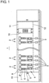
- FIG 1 a textile machine 1 designed as a spinning machine and having a large number of workstations 2 arranged next to one another is shown in a simplified representation.
- Each work station 2 of the textile machine 1 comprises a sliver source 3, which can be designed as a spinning can, for example in a work station 2 designed as a spinning station, a drafting system 4, a spinning device 5, a pair of take-off rollers 6, a yarn cleaner 7, a thread laying device 8, a thread store 17 and a cheese 9 of a winding device.
- a service trolley 10 is movably mounted on rails 11, 12 running along the textile machine 1.
- a drive unit 13 arranged at one end of the textile machine 1 is used to drive the textile machine 1.
- the service trolley 10 In the event of a malfunction at a workstation 2 in the area of the thread storage 17, the service trolley 10 is positioned along the textile machine 1 at the workstation 2 having the malfunction. In the event of a thread break, for example within the thread storage 17, the service trolley 10 is moved to the relevant workstation 2, positions itself there and begins troubleshooting using the troubleshooting means not shown here. In the event of a thread break within the thread store 17, the service trolley 10 can find the torn thread end lying on the peripheral surface of the cross-wound bobbin 9 via a thread search nozzle, which is one of the fault means.
- this thread end is, as usual, transported back into the area of the spinning device 5 by known handling devices that are part of the interference suppression means, after appropriate preparation, and kept there ready for the actual spinning process.
- a defined length of thread is unwound via the drive of the cheeses 9 and temporarily stored in the thread store 17.
Landscapes
- Engineering & Computer Science (AREA)
- Textile Engineering (AREA)
- Mechanical Engineering (AREA)
- Quality & Reliability (AREA)
- Spinning Or Twisting Of Yarns (AREA)
- Replacing, Conveying, And Pick-Finding For Filamentary Materials (AREA)
Claims (7)
- Machine textile (1) comportant une pluralité de postes de travail (2) produisant des bobines de même type, en particulier des bobines croisées (9), lesquels présentent respectivement un réservoir de fil (17) et au moins un chariot de service (10) pouvant se déplacer le long des postes de travail (2),
dans laquelle le chariot de service (10) présente un moyen antiparasitage permettant d'éliminer automatiquement des états d'erreur apparaissant dans le réservoir de fil (17) et/ou devant être attribués au réservoir de fil (17), caractérisée en ce que le moyen antiparasitage présente un dispositif d'inspection optique permettant d'examiner le réservoir de fil (17). - Machine textile (1) selon la revendication 1, caractérisée en ce que le moyen antiparasitage présente un groupe de nettoyage permettant de supprimer les restes de fil du réservoir de fil (17).
- Machine textile (1) selon l'une ou plusieurs des revendications précédentes, caractérisée en ce que le chariot de service (10) présente un dispositif de liaison de fil.
- Machine textile (1) selon la revendication 3, caractérisée en ce que le dispositif de liaison de fil présente une buse de recherche de fil et un moyen de manipulation permettant de positionner l'extrémité de fil libre dans la zone d'un élément de liaison de fil, en particulier d'une unité d'épissure et/ou de nouage.
- Machine textile (1) selon l'une ou plusieurs des revendications précédentes 3 à 4, caractérisée en ce que le dispositif de liaison de fil est conçu pour disposer l'extrémité de fil libre sur un poste de filage du poste de travail (2).
- Machine textile (1) selon l'une ou plusieurs des revendications précédentes, caractérisée en ce que le chariot de service (10) présente un moyen d'inspection de fil, en particulier un moyen d'inspection de fil à effet optique.
- Chariot de service (10) destiné à une machine textile (1) selon l'une ou plusieurs des revendications 1 à 6, lequel présente un moyen antiparasitage permettant d'éliminer automatiquement des états d'erreur apparaissant dans le réservoir de fil (17) et/ou devant être attribués au réservoir de fil (17), caractérisé en ce que le moyen antiparasitage présente un dispositif d'inspection optique permettant d'examiner le réservoir de fil (17).
Applications Claiming Priority (1)
| Application Number | Priority Date | Filing Date | Title |
|---|---|---|---|
| DE102020111342.0A DE102020111342A1 (de) | 2020-04-27 | 2020-04-27 | Textilmaschine sowie Servicewagen für Textilmaschinen |
Publications (2)
| Publication Number | Publication Date |
|---|---|
| EP3904253A1 EP3904253A1 (fr) | 2021-11-03 |
| EP3904253B1 true EP3904253B1 (fr) | 2024-02-21 |
Family
ID=75639727
Family Applications (1)
| Application Number | Title | Priority Date | Filing Date |
|---|---|---|---|
| EP21169764.4A Active EP3904253B1 (fr) | 2020-04-27 | 2021-04-22 | Machine textile, ainsi que chariot de service pour machines textiles |
Country Status (5)
| Country | Link |
|---|---|
| US (1) | US20210348306A1 (fr) |
| EP (1) | EP3904253B1 (fr) |
| CN (1) | CN113636418B (fr) |
| BR (1) | BR102021007635A2 (fr) |
| DE (1) | DE102020111342A1 (fr) |
Families Citing this family (1)
| Publication number | Priority date | Publication date | Assignee | Title |
|---|---|---|---|---|
| CN117933970A (zh) | 2023-09-15 | 2024-04-26 | 浙江恒逸石化有限公司 | 丝路巡检设备的控制方法、装置、设备以及存储介质 |
Family Cites Families (19)
| Publication number | Priority date | Publication date | Assignee | Title |
|---|---|---|---|---|
| DE3701796C2 (de) * | 1987-01-22 | 1998-06-04 | Zinser Textilmaschinen Gmbh | Verfahren und Vorrichtung zum Steuern des Einsatzes von Bedienorganen in einer Spinnereianlage |
| DE3813368C2 (de) * | 1988-04-21 | 1996-02-29 | Fritz Stahlecker | Verfahren und Vorrichtung zum Erzeugen von Spulen |
| DE3828189A1 (de) * | 1988-08-19 | 1990-03-01 | Fritz Stahlecker | Verfahren und vorrichtung zum anspinnen eines doppelfadens nach einem fadenbruch |
| DE3828323A1 (de) * | 1988-08-20 | 1990-02-22 | Fritz Stahlecker | Verfahren und vorrichtung zum aufnehmen eines fadenendes einer spule beim anspinnen |
| DE3908463A1 (de) * | 1989-03-15 | 1990-09-20 | Stahlecker Fritz | Vorrichtung zum zwischenspeichern eines doppelfadens |
| DE10139075A1 (de) | 2001-08-09 | 2003-02-20 | Schlafhorst & Co W | Offenend-Rotorspinnmaschine |
| DE102006047288A1 (de) | 2006-10-06 | 2008-04-10 | Oerlikon Textile Gmbh & Co. Kg | Arbeitsstelle einer Textilmaschine |
| JP2011173674A (ja) * | 2010-02-24 | 2011-09-08 | Murata Machinery Ltd | 糸巻取機 |
| JP6188271B2 (ja) * | 2011-06-30 | 2017-08-30 | 村田機械株式会社 | ドラフトローラ及びそれを用いて紡績する方法、紡績ユニット、並びに紡績機 |
| DE102012102695A1 (de) * | 2012-03-29 | 2013-10-02 | Maschinenfabrik Rieter Ag | Vorspinnmaschine mit einer Anordnung zur Detektion und Entfernung von Garnfehlern |
| DE102012008691A1 (de) * | 2012-04-28 | 2013-10-31 | Oerlikon Textile Gmbh & Co. Kg | Verfahren und Vorrichtung zum Betreiben von Arbeitsstellen einer Offenend-Rotorspinnmaschine |
| DE102014008735A1 (de) * | 2014-06-12 | 2015-12-17 | Saurer Germany Gmbh & Co. Kg | Verfahren und Vorrichtung zur Steuerung des Unterdruckes an einer Fadenfang- oder Reinigungsdüse einer Arbeitsstelle einer Auflaufspulen herstellenden Textilmaschine |
| DE102016115732A1 (de) * | 2016-08-24 | 2018-03-01 | Saurer Germany Gmbh & Co. Kg | Fadenspleißvorrichtung für eine Arbeitsstelle einer Kreuzspulen herstellenden Textilmaschine |
| DE102016119983A1 (de) | 2016-10-20 | 2018-04-26 | Maschinenfabrik Rieter Ag | Pneumatisches Fadenspeicherorgan, Arbeitsstelle einer Textilmaschine mit einem Fadenspeicherorgan und Textilmaschine mit einer Vielzahl von Arbeitsstellen mit einem Fadenspeicherorgan |
| DE102017107112A1 (de) * | 2017-04-03 | 2018-10-04 | Saurer Germany Gmbh & Co. Kg | Arbeitsstelle einer Kreuzspulen herstellenden Textilmaschine |
| DE102017117743A1 (de) * | 2017-08-04 | 2019-02-07 | Saurer Spinning Solutions Gmbh & Co. Kg | Vorrichtung zur Ausreinigung von Garnfehlern aus einem Garn |
| DE102017129580A1 (de) * | 2017-12-12 | 2019-06-13 | Saurer Spinning Solutions Gmbh & Co. Kg | Rotationsspleißer für eine Arbeitsstelle auf einer Kreuzspulen herstellenden Textilmaschine |
| JP2019196244A (ja) * | 2018-05-09 | 2019-11-14 | 村田機械株式会社 | 糸巻取機及び糸巻取方法 |
| CZ2019198A3 (cs) * | 2019-03-29 | 2020-10-07 | Rieter Cz S.R.O. | Způsob řízení prostředků pracovního místa textilního stroje a zařízení k jeho provádění |
-
2020
- 2020-04-27 DE DE102020111342.0A patent/DE102020111342A1/de active Pending
-
2021
- 2021-04-22 BR BR102021007635-6A patent/BR102021007635A2/pt unknown
- 2021-04-22 EP EP21169764.4A patent/EP3904253B1/fr active Active
- 2021-04-25 CN CN202110446240.4A patent/CN113636418B/zh active Active
- 2021-04-26 US US17/240,214 patent/US20210348306A1/en not_active Abandoned
Also Published As
| Publication number | Publication date |
|---|---|
| EP3904253A1 (fr) | 2021-11-03 |
| US20210348306A1 (en) | 2021-11-11 |
| DE102020111342A1 (de) | 2021-10-28 |
| CN113636418A (zh) | 2021-11-12 |
| CN113636418B (zh) | 2023-12-05 |
| BR102021007635A2 (pt) | 2021-11-09 |
Similar Documents
| Publication | Publication Date | Title |
|---|---|---|
| EP2338818B1 (fr) | Procédé de fonctionnement d'un poste de travail d'une bobineuse et poste de travail d'une bobineuse | |
| DE102014103193A1 (de) | Spinnmaschine und Verfahren zum Übergeben eines Garnes an eine Anspinnvorrichtung | |
| DE102016007779A1 (de) | Verfahren zum Überwachen des ordnungsgemäßen Arbeitens der Spinnstellen einer Ringspinnmaschine | |
| EP2606166B1 (fr) | Machine textile | |
| EP2072648A2 (fr) | Procédé de fonctionnement d'une machine textile | |
| EP1995200A2 (fr) | Procédé et dispositif de fonctionnement d'un dispositif de bobinage d'une machine textile produisant des bobines croisées | |
| EP3052416A1 (fr) | Épurateur de fil et poste de filage d'un métier à filer équipé dudit épurateur, ainsi que procédé permettant de faire fonctionner un poste de filage | |
| EP2388222B1 (fr) | Procédé de fabrication de cannettes de filature | |
| DE19917968B4 (de) | Serviceaggregat für eine Kreuzspulen herstellende Textilmaschine | |
| DE19905860A1 (de) | Verfahren zum Betreiben einer Arbeitsstelle einer Kreuzspulen herstellenden Textilmaschine | |
| EP3904253B1 (fr) | Machine textile, ainsi que chariot de service pour machines textiles | |
| DE102015118987A1 (de) | Verfahren zum Betreiben einer Spinnmaschine mit einer vollautomatischen Anspinnvorrichtung sowie Spinnmaschine mit einer vollautomatischen Anspinnvorrichtung | |
| EP3581687B1 (fr) | Procédé et dispositif permettant de régler l'enroulement des bobines | |
| WO2007033771A1 (fr) | Procede de fonctionnement d'un poste de travail dote d'une machine textile fabricant des bobines croisees | |
| DE102012005988A1 (de) | Verfahren zum Betreiben einer Arbeitsstelle einer Kreuzspulen herstellenden Textilmaschine | |
| EP2500452B2 (fr) | Poste de travail pour métier à tisser à rotor à extrémité ouverte | |
| DE102010035762A1 (de) | Arbeitsstelle einer Spulmaschine und Verfahren zum Betreiben der Arbeitsstelle | |
| EP4155442B1 (fr) | Métier à filer à anneaux/disrobineuse automatique | |
| EP3693308B1 (fr) | Tube de stockage de fil pour un poste de travail d'une machine textile ainsi que poste de travail d'une machine textile | |
| EP3957783B1 (fr) | Machine textile dotée d'une pluralité de postes de travail similaires | |
| EP3527703B1 (fr) | Procédé de fonctionnement d'un poste de filage d'un métier à filer continu à anneaux après un processus de levée | |
| EP0905294A2 (fr) | Surveillance de garnissage dans une machine de préparation à la filature | |
| DE102022106747A1 (de) | Verfahren und Vorrichtung zum Betreiben eines Kreuzspulautomaten, auf dessen Arbeitsstellen großvolumige Kreuzspulen gewickelt werden | |
| DE102020124125A1 (de) | Kreuzspulen herstellende Textilmaschine | |
| DE102021108779A1 (de) | Verfahren zum Betreiben einer Spinnmaschine sowie Spinnmaschine |
Legal Events
| Date | Code | Title | Description |
|---|---|---|---|
| PUAI | Public reference made under article 153(3) epc to a published international application that has entered the european phase |
Free format text: ORIGINAL CODE: 0009012 |
|
| STAA | Information on the status of an ep patent application or granted ep patent |
Free format text: STATUS: THE APPLICATION HAS BEEN PUBLISHED |
|
| AK | Designated contracting states |
Kind code of ref document: A1 Designated state(s): AL AT BE BG CH CY CZ DE DK EE ES FI FR GB GR HR HU IE IS IT LI LT LU LV MC MK MT NL NO PL PT RO RS SE SI SK SM TR |
|
| B565 | Issuance of search results under rule 164(2) epc |
Effective date: 20210913 |
|
| STAA | Information on the status of an ep patent application or granted ep patent |
Free format text: STATUS: REQUEST FOR EXAMINATION WAS MADE |
|
| 17P | Request for examination filed |
Effective date: 20220503 |
|
| RBV | Designated contracting states (corrected) |
Designated state(s): AL AT BE BG CH CY CZ DE DK EE ES FI FR GB GR HR HU IE IS IT LI LT LU LV MC MK MT NL NO PL PT RO RS SE SI SK SM TR |
|
| RIC1 | Information provided on ipc code assigned before grant |
Ipc: B65H 51/20 20060101ALI20231019BHEP Ipc: B65H 54/26 20060101AFI20231019BHEP |
|
| GRAP | Despatch of communication of intention to grant a patent |
Free format text: ORIGINAL CODE: EPIDOSNIGR1 |
|
| STAA | Information on the status of an ep patent application or granted ep patent |
Free format text: STATUS: GRANT OF PATENT IS INTENDED |
|
| INTG | Intention to grant announced |
Effective date: 20231124 |
|
| GRAS | Grant fee paid |
Free format text: ORIGINAL CODE: EPIDOSNIGR3 |
|
| GRAA | (expected) grant |
Free format text: ORIGINAL CODE: 0009210 |
|
| STAA | Information on the status of an ep patent application or granted ep patent |
Free format text: STATUS: THE PATENT HAS BEEN GRANTED |
|
| AK | Designated contracting states |
Kind code of ref document: B1 Designated state(s): AL AT BE BG CH CY CZ DE DK EE ES FI FR GB GR HR HU IE IS IT LI LT LU LV MC MK MT NL NO PL PT RO RS SE SI SK SM TR |
|
| REG | Reference to a national code |
Ref country code: GB Ref legal event code: FG4D Free format text: NOT ENGLISH |
|
| REG | Reference to a national code |
Ref country code: CH Ref legal event code: EP |
|
| REG | Reference to a national code |
Ref country code: DE Ref legal event code: R096 Ref document number: 502021002725 Country of ref document: DE |
|
| REG | Reference to a national code |
Ref country code: IE Ref legal event code: FG4D Free format text: LANGUAGE OF EP DOCUMENT: GERMAN |
|
| REG | Reference to a national code |
Ref country code: LT Ref legal event code: MG9D |
|
| REG | Reference to a national code |
Ref country code: NL Ref legal event code: MP Effective date: 20240221 |
|
| PG25 | Lapsed in a contracting state [announced via postgrant information from national office to epo] |
Ref country code: IS Free format text: LAPSE BECAUSE OF FAILURE TO SUBMIT A TRANSLATION OF THE DESCRIPTION OR TO PAY THE FEE WITHIN THE PRESCRIBED TIME-LIMIT Effective date: 20240621 |
|
| PG25 | Lapsed in a contracting state [announced via postgrant information from national office to epo] |
Ref country code: LT Free format text: LAPSE BECAUSE OF FAILURE TO SUBMIT A TRANSLATION OF THE DESCRIPTION OR TO PAY THE FEE WITHIN THE PRESCRIBED TIME-LIMIT Effective date: 20240221 |
|
| PG25 | Lapsed in a contracting state [announced via postgrant information from national office to epo] |
Ref country code: GR Free format text: LAPSE BECAUSE OF FAILURE TO SUBMIT A TRANSLATION OF THE DESCRIPTION OR TO PAY THE FEE WITHIN THE PRESCRIBED TIME-LIMIT Effective date: 20240522 |
|
| PG25 | Lapsed in a contracting state [announced via postgrant information from national office to epo] |
Ref country code: HR Free format text: LAPSE BECAUSE OF FAILURE TO SUBMIT A TRANSLATION OF THE DESCRIPTION OR TO PAY THE FEE WITHIN THE PRESCRIBED TIME-LIMIT Effective date: 20240221 Ref country code: NL Free format text: LAPSE BECAUSE OF FAILURE TO SUBMIT A TRANSLATION OF THE DESCRIPTION OR TO PAY THE FEE WITHIN THE PRESCRIBED TIME-LIMIT Effective date: 20240221 Ref country code: RS Free format text: LAPSE BECAUSE OF FAILURE TO SUBMIT A TRANSLATION OF THE DESCRIPTION OR TO PAY THE FEE WITHIN THE PRESCRIBED TIME-LIMIT Effective date: 20240521 |
|
| PG25 | Lapsed in a contracting state [announced via postgrant information from national office to epo] |
Ref country code: ES Free format text: LAPSE BECAUSE OF FAILURE TO SUBMIT A TRANSLATION OF THE DESCRIPTION OR TO PAY THE FEE WITHIN THE PRESCRIBED TIME-LIMIT Effective date: 20240221 |
|
| PG25 | Lapsed in a contracting state [announced via postgrant information from national office to epo] |
Ref country code: RS Free format text: LAPSE BECAUSE OF FAILURE TO SUBMIT A TRANSLATION OF THE DESCRIPTION OR TO PAY THE FEE WITHIN THE PRESCRIBED TIME-LIMIT Effective date: 20240521 Ref country code: NO Free format text: LAPSE BECAUSE OF FAILURE TO SUBMIT A TRANSLATION OF THE DESCRIPTION OR TO PAY THE FEE WITHIN THE PRESCRIBED TIME-LIMIT Effective date: 20240521 Ref country code: NL Free format text: LAPSE BECAUSE OF FAILURE TO SUBMIT A TRANSLATION OF THE DESCRIPTION OR TO PAY THE FEE WITHIN THE PRESCRIBED TIME-LIMIT Effective date: 20240221 Ref country code: LT Free format text: LAPSE BECAUSE OF FAILURE TO SUBMIT A TRANSLATION OF THE DESCRIPTION OR TO PAY THE FEE WITHIN THE PRESCRIBED TIME-LIMIT Effective date: 20240221 Ref country code: IS Free format text: LAPSE BECAUSE OF FAILURE TO SUBMIT A TRANSLATION OF THE DESCRIPTION OR TO PAY THE FEE WITHIN THE PRESCRIBED TIME-LIMIT Effective date: 20240621 Ref country code: HR Free format text: LAPSE BECAUSE OF FAILURE TO SUBMIT A TRANSLATION OF THE DESCRIPTION OR TO PAY THE FEE WITHIN THE PRESCRIBED TIME-LIMIT Effective date: 20240221 Ref country code: GR Free format text: LAPSE BECAUSE OF FAILURE TO SUBMIT A TRANSLATION OF THE DESCRIPTION OR TO PAY THE FEE WITHIN THE PRESCRIBED TIME-LIMIT Effective date: 20240522 Ref country code: FI Free format text: LAPSE BECAUSE OF FAILURE TO SUBMIT A TRANSLATION OF THE DESCRIPTION OR TO PAY THE FEE WITHIN THE PRESCRIBED TIME-LIMIT Effective date: 20240221 Ref country code: ES Free format text: LAPSE BECAUSE OF FAILURE TO SUBMIT A TRANSLATION OF THE DESCRIPTION OR TO PAY THE FEE WITHIN THE PRESCRIBED TIME-LIMIT Effective date: 20240221 Ref country code: BG Free format text: LAPSE BECAUSE OF FAILURE TO SUBMIT A TRANSLATION OF THE DESCRIPTION OR TO PAY THE FEE WITHIN THE PRESCRIBED TIME-LIMIT Effective date: 20240221 |
|
| PG25 | Lapsed in a contracting state [announced via postgrant information from national office to epo] |
Ref country code: PT Free format text: LAPSE BECAUSE OF FAILURE TO SUBMIT A TRANSLATION OF THE DESCRIPTION OR TO PAY THE FEE WITHIN THE PRESCRIBED TIME-LIMIT Effective date: 20240621 Ref country code: PL Free format text: LAPSE BECAUSE OF FAILURE TO SUBMIT A TRANSLATION OF THE DESCRIPTION OR TO PAY THE FEE WITHIN THE PRESCRIBED TIME-LIMIT Effective date: 20240221 |
|
| PG25 | Lapsed in a contracting state [announced via postgrant information from national office to epo] |
Ref country code: SE Free format text: LAPSE BECAUSE OF FAILURE TO SUBMIT A TRANSLATION OF THE DESCRIPTION OR TO PAY THE FEE WITHIN THE PRESCRIBED TIME-LIMIT Effective date: 20240221 Ref country code: PT Free format text: LAPSE BECAUSE OF FAILURE TO SUBMIT A TRANSLATION OF THE DESCRIPTION OR TO PAY THE FEE WITHIN THE PRESCRIBED TIME-LIMIT Effective date: 20240621 Ref country code: PL Free format text: LAPSE BECAUSE OF FAILURE TO SUBMIT A TRANSLATION OF THE DESCRIPTION OR TO PAY THE FEE WITHIN THE PRESCRIBED TIME-LIMIT Effective date: 20240221 Ref country code: LV Free format text: LAPSE BECAUSE OF FAILURE TO SUBMIT A TRANSLATION OF THE DESCRIPTION OR TO PAY THE FEE WITHIN THE PRESCRIBED TIME-LIMIT Effective date: 20240221 |
|
| PG25 | Lapsed in a contracting state [announced via postgrant information from national office to epo] |
Ref country code: DK Free format text: LAPSE BECAUSE OF FAILURE TO SUBMIT A TRANSLATION OF THE DESCRIPTION OR TO PAY THE FEE WITHIN THE PRESCRIBED TIME-LIMIT Effective date: 20240221 |
|
| PG25 | Lapsed in a contracting state [announced via postgrant information from national office to epo] |
Ref country code: SM Free format text: LAPSE BECAUSE OF FAILURE TO SUBMIT A TRANSLATION OF THE DESCRIPTION OR TO PAY THE FEE WITHIN THE PRESCRIBED TIME-LIMIT Effective date: 20240221 |
|
| PG25 | Lapsed in a contracting state [announced via postgrant information from national office to epo] |
Ref country code: EE Free format text: LAPSE BECAUSE OF FAILURE TO SUBMIT A TRANSLATION OF THE DESCRIPTION OR TO PAY THE FEE WITHIN THE PRESCRIBED TIME-LIMIT Effective date: 20240221 |
|
| PG25 | Lapsed in a contracting state [announced via postgrant information from national office to epo] |
Ref country code: SK Free format text: LAPSE BECAUSE OF FAILURE TO SUBMIT A TRANSLATION OF THE DESCRIPTION OR TO PAY THE FEE WITHIN THE PRESCRIBED TIME-LIMIT Effective date: 20240221 |
|
| PG25 | Lapsed in a contracting state [announced via postgrant information from national office to epo] |
Ref country code: SM Free format text: LAPSE BECAUSE OF FAILURE TO SUBMIT A TRANSLATION OF THE DESCRIPTION OR TO PAY THE FEE WITHIN THE PRESCRIBED TIME-LIMIT Effective date: 20240221 Ref country code: SK Free format text: LAPSE BECAUSE OF FAILURE TO SUBMIT A TRANSLATION OF THE DESCRIPTION OR TO PAY THE FEE WITHIN THE PRESCRIBED TIME-LIMIT Effective date: 20240221 Ref country code: RO Free format text: LAPSE BECAUSE OF FAILURE TO SUBMIT A TRANSLATION OF THE DESCRIPTION OR TO PAY THE FEE WITHIN THE PRESCRIBED TIME-LIMIT Effective date: 20240221 Ref country code: EE Free format text: LAPSE BECAUSE OF FAILURE TO SUBMIT A TRANSLATION OF THE DESCRIPTION OR TO PAY THE FEE WITHIN THE PRESCRIBED TIME-LIMIT Effective date: 20240221 Ref country code: DK Free format text: LAPSE BECAUSE OF FAILURE TO SUBMIT A TRANSLATION OF THE DESCRIPTION OR TO PAY THE FEE WITHIN THE PRESCRIBED TIME-LIMIT Effective date: 20240221 |
|
| PG25 | Lapsed in a contracting state [announced via postgrant information from national office to epo] |
Ref country code: MC Free format text: LAPSE BECAUSE OF FAILURE TO SUBMIT A TRANSLATION OF THE DESCRIPTION OR TO PAY THE FEE WITHIN THE PRESCRIBED TIME-LIMIT Effective date: 20240221 |
|
| REG | Reference to a national code |
Ref country code: DE Ref legal event code: R097 Ref document number: 502021002725 Country of ref document: DE |
|
| PG25 | Lapsed in a contracting state [announced via postgrant information from national office to epo] |
Ref country code: MC Free format text: LAPSE BECAUSE OF FAILURE TO SUBMIT A TRANSLATION OF THE DESCRIPTION OR TO PAY THE FEE WITHIN THE PRESCRIBED TIME-LIMIT Effective date: 20240221 |
|
| PG25 | Lapsed in a contracting state [announced via postgrant information from national office to epo] |
Ref country code: LU Free format text: LAPSE BECAUSE OF NON-PAYMENT OF DUE FEES Effective date: 20240422 |
|
| PLBE | No opposition filed within time limit |
Free format text: ORIGINAL CODE: 0009261 |
|
| STAA | Information on the status of an ep patent application or granted ep patent |
Free format text: STATUS: NO OPPOSITION FILED WITHIN TIME LIMIT |
|
| REG | Reference to a national code |
Ref country code: BE Ref legal event code: MM Effective date: 20240430 |
|
| PG25 | Lapsed in a contracting state [announced via postgrant information from national office to epo] |
Ref country code: LU Free format text: LAPSE BECAUSE OF NON-PAYMENT OF DUE FEES Effective date: 20240422 |
|
| PG25 | Lapsed in a contracting state [announced via postgrant information from national office to epo] |
Ref country code: BE Free format text: LAPSE BECAUSE OF NON-PAYMENT OF DUE FEES Effective date: 20240430 |
|
| PG25 | Lapsed in a contracting state [announced via postgrant information from national office to epo] |
Ref country code: FR Free format text: LAPSE BECAUSE OF NON-PAYMENT OF DUE FEES Effective date: 20240430 |
|
| 26N | No opposition filed |
Effective date: 20241122 |
|
| PG25 | Lapsed in a contracting state [announced via postgrant information from national office to epo] |
Ref country code: FR Free format text: LAPSE BECAUSE OF NON-PAYMENT OF DUE FEES Effective date: 20240430 Ref country code: BE Free format text: LAPSE BECAUSE OF NON-PAYMENT OF DUE FEES Effective date: 20240430 |
|
| PG25 | Lapsed in a contracting state [announced via postgrant information from national office to epo] |
Ref country code: IE Free format text: LAPSE BECAUSE OF NON-PAYMENT OF DUE FEES Effective date: 20240422 |
|
| PG25 | Lapsed in a contracting state [announced via postgrant information from national office to epo] |
Ref country code: SI Free format text: LAPSE BECAUSE OF FAILURE TO SUBMIT A TRANSLATION OF THE DESCRIPTION OR TO PAY THE FEE WITHIN THE PRESCRIBED TIME-LIMIT Effective date: 20240221 |
|
| PGFP | Annual fee paid to national office [announced via postgrant information from national office to epo] |
Ref country code: DE Payment date: 20250417 Year of fee payment: 5 |
|
| PGFP | Annual fee paid to national office [announced via postgrant information from national office to epo] |
Ref country code: IT Payment date: 20250430 Year of fee payment: 5 |
|
| PGFP | Annual fee paid to national office [announced via postgrant information from national office to epo] |
Ref country code: CH Payment date: 20250501 Year of fee payment: 5 |
|
| PGFP | Annual fee paid to national office [announced via postgrant information from national office to epo] |
Ref country code: AT Payment date: 20250721 Year of fee payment: 5 |
|
| PGFP | Annual fee paid to national office [announced via postgrant information from national office to epo] |
Ref country code: TR Payment date: 20250414 Year of fee payment: 5 |
|
| PGFP | Annual fee paid to national office [announced via postgrant information from national office to epo] |
Ref country code: CZ Payment date: 20250409 Year of fee payment: 5 |
|
| PG25 | Lapsed in a contracting state [announced via postgrant information from national office to epo] |
Ref country code: CY Free format text: LAPSE BECAUSE OF FAILURE TO SUBMIT A TRANSLATION OF THE DESCRIPTION OR TO PAY THE FEE WITHIN THE PRESCRIBED TIME-LIMIT; INVALID AB INITIO Effective date: 20210422 |
|
| PG25 | Lapsed in a contracting state [announced via postgrant information from national office to epo] |
Ref country code: HU Free format text: LAPSE BECAUSE OF FAILURE TO SUBMIT A TRANSLATION OF THE DESCRIPTION OR TO PAY THE FEE WITHIN THE PRESCRIBED TIME-LIMIT; INVALID AB INITIO Effective date: 20210422 |
|
| GBPC | Gb: european patent ceased through non-payment of renewal fee |
Effective date: 20250422 |
|
| PG25 | Lapsed in a contracting state [announced via postgrant information from national office to epo] |
Ref country code: GB Free format text: LAPSE BECAUSE OF NON-PAYMENT OF DUE FEES Effective date: 20250422 |
|
| REG | Reference to a national code |
Ref country code: DE Ref legal event code: R081 Ref document number: 502021002725 Country of ref document: DE Owner name: RIETER AUTOMATIC WINDER GMBH, DE Free format text: FORMER OWNER: SAURER SPINNING SOLUTIONS GMBH & CO. KG, 52531 UEBACH-PALENBERG, DE |