EP3904667B1 - Ensemble filtre à carburant - Google Patents
Ensemble filtre à carburant Download PDFInfo
- Publication number
- EP3904667B1 EP3904667B1 EP21163218.7A EP21163218A EP3904667B1 EP 3904667 B1 EP3904667 B1 EP 3904667B1 EP 21163218 A EP21163218 A EP 21163218A EP 3904667 B1 EP3904667 B1 EP 3904667B1
- Authority
- EP
- European Patent Office
- Prior art keywords
- filter
- relief
- fuel
- valve
- passage
- Prior art date
- Legal status (The legal status is an assumption and is not a legal conclusion. Google has not performed a legal analysis and makes no representation as to the accuracy of the status listed.)
- Active
Links
Images


Classifications
-
- F—MECHANICAL ENGINEERING; LIGHTING; HEATING; WEAPONS; BLASTING
- F02—COMBUSTION ENGINES; HOT-GAS OR COMBUSTION-PRODUCT ENGINE PLANTS
- F02M—SUPPLYING COMBUSTION ENGINES IN GENERAL WITH COMBUSTIBLE MIXTURES OR CONSTITUENTS THEREOF
- F02M37/00—Apparatus or systems for feeding liquid fuel from storage containers to carburettors or fuel-injection apparatus; Arrangements for purifying liquid fuel specially adapted for, or arranged on, internal-combustion engines
- F02M37/22—Arrangements for purifying liquid fuel specially adapted for, or arranged on, internal-combustion engines, e.g. arrangements in the feeding system
- F02M37/32—Arrangements for purifying liquid fuel specially adapted for, or arranged on, internal-combustion engines, e.g. arrangements in the feeding system characterised by filters or filter arrangements
- F02M37/36—Arrangements for purifying liquid fuel specially adapted for, or arranged on, internal-combustion engines, e.g. arrangements in the feeding system characterised by filters or filter arrangements with bypass means
-
- F—MECHANICAL ENGINEERING; LIGHTING; HEATING; WEAPONS; BLASTING
- F02—COMBUSTION ENGINES; HOT-GAS OR COMBUSTION-PRODUCT ENGINE PLANTS
- F02M—SUPPLYING COMBUSTION ENGINES IN GENERAL WITH COMBUSTIBLE MIXTURES OR CONSTITUENTS THEREOF
- F02M37/00—Apparatus or systems for feeding liquid fuel from storage containers to carburettors or fuel-injection apparatus; Arrangements for purifying liquid fuel specially adapted for, or arranged on, internal-combustion engines
- F02M37/22—Arrangements for purifying liquid fuel specially adapted for, or arranged on, internal-combustion engines, e.g. arrangements in the feeding system
- F02M37/32—Arrangements for purifying liquid fuel specially adapted for, or arranged on, internal-combustion engines, e.g. arrangements in the feeding system characterised by filters or filter arrangements
- F02M37/34—Arrangements for purifying liquid fuel specially adapted for, or arranged on, internal-combustion engines, e.g. arrangements in the feeding system characterised by filters or filter arrangements by the filter structure, e.g. honeycomb, mesh or fibrous
-
- B—PERFORMING OPERATIONS; TRANSPORTING
- B01—PHYSICAL OR CHEMICAL PROCESSES OR APPARATUS IN GENERAL
- B01D—SEPARATION
- B01D29/00—Filters with filtering elements stationary during filtration, e.g. pressure or suction filters, not covered by groups B01D24/00 - B01D27/00; Filtering elements therefor
- B01D29/11—Filters with filtering elements stationary during filtration, e.g. pressure or suction filters, not covered by groups B01D24/00 - B01D27/00; Filtering elements therefor with bag, cage, hose, tube, sleeve or like filtering elements
- B01D29/13—Supported filter elements
- B01D29/15—Supported filter elements arranged for inward flow filtration
- B01D29/21—Supported filter elements arranged for inward flow filtration with corrugated, folded or wound sheets
-
- B—PERFORMING OPERATIONS; TRANSPORTING
- B01—PHYSICAL OR CHEMICAL PROCESSES OR APPARATUS IN GENERAL
- B01D—SEPARATION
- B01D35/00—Filtering devices having features not specifically covered by groups B01D24/00 - B01D33/00, or for applications not specifically covered by groups B01D24/00 - B01D33/00; Auxiliary devices for filtration; Filter housing constructions
- B01D35/14—Safety devices specially adapted for filtration; Devices for indicating clogging
- B01D35/147—Bypass or safety valves
- B01D35/1475—Pressure relief valves or pressure control valves
-
- B—PERFORMING OPERATIONS; TRANSPORTING
- B01—PHYSICAL OR CHEMICAL PROCESSES OR APPARATUS IN GENERAL
- B01D—SEPARATION
- B01D35/00—Filtering devices having features not specifically covered by groups B01D24/00 - B01D33/00, or for applications not specifically covered by groups B01D24/00 - B01D33/00; Auxiliary devices for filtration; Filter housing constructions
- B01D35/14—Safety devices specially adapted for filtration; Devices for indicating clogging
- B01D35/153—Anti-leakage or anti-return valves
-
- B—PERFORMING OPERATIONS; TRANSPORTING
- B01—PHYSICAL OR CHEMICAL PROCESSES OR APPARATUS IN GENERAL
- B01D—SEPARATION
- B01D36/00—Filter circuits or combinations of filters with other separating devices
- B01D36/003—Filters in combination with devices for the removal of liquids
- B01D36/008—Means to filter or treat the separated liquid
-
- F—MECHANICAL ENGINEERING; LIGHTING; HEATING; WEAPONS; BLASTING
- F02—COMBUSTION ENGINES; HOT-GAS OR COMBUSTION-PRODUCT ENGINE PLANTS
- F02M—SUPPLYING COMBUSTION ENGINES IN GENERAL WITH COMBUSTIBLE MIXTURES OR CONSTITUENTS THEREOF
- F02M37/00—Apparatus or systems for feeding liquid fuel from storage containers to carburettors or fuel-injection apparatus; Arrangements for purifying liquid fuel specially adapted for, or arranged on, internal-combustion engines
- F02M37/22—Arrangements for purifying liquid fuel specially adapted for, or arranged on, internal-combustion engines, e.g. arrangements in the feeding system
- F02M37/32—Arrangements for purifying liquid fuel specially adapted for, or arranged on, internal-combustion engines, e.g. arrangements in the feeding system characterised by filters or filter arrangements
- F02M37/42—Installation or removal of filters
-
- B—PERFORMING OPERATIONS; TRANSPORTING
- B01—PHYSICAL OR CHEMICAL PROCESSES OR APPARATUS IN GENERAL
- B01D—SEPARATION
- B01D2201/00—Details relating to filtering apparatus
- B01D2201/29—Filter cartridge constructions
- B01D2201/291—End caps
Definitions
- This disclosure relates to fuel filters and in particular to fuel filters having a filter bypass valve and shutoff valves on the fuel inlet and outlets.
- Known fuel filters comprise a filter bowl suitable for housing a filter element, a filter element, and a manifold to which the filter bowl may be reversibly attached.
- the manifold includes fuel inlet and outlet ports.
- the manifold, filter bowl and the filter element define a flow path in which fuel flows into the manifold through the fuel inlet port, through the filter element and out of the manifold via the fuel outlet port.
- Filters are known from DE 103 15 052 A1 , IT MI20 111 315 A1 , FR 2 979 387 A1 and EP 3 907 396 A1 .
- a fuel filter comprising a manifold, a connector element, a filter bowl, a filter element, a shutoff valve, an inlet port, an inlet passage, an outlet port, an outlet passage and a relief valve in which the connector element is fixed to the manifold, and the filter bowl is reversibly fixed to the connector element, the filter bowl is adapted to reversibly receive the filter element and is so configured that when the filter element is located within the filter bowl and the filter bowl attached to the connector element the filter element divides the space defined by the connector element and filter bowl into an inlet filter chamber and an outlet filter chamber, the inlet port is incorporated in the manifold, and the inlet port and inlet filter chamber are in fluid communication via the inlet passage, the outlet port is incorporated in the manifold and the outlet port and outlet filter chamber are in fluid communication via the outlet passage, the shutoff valve is biased by a biasing means into a closed configuration which prevents fuel flowing along the inlet and outlet passages when the filter bowl with
- An advantage of the fuel filter of the disclosure is that when the filter bowl with the filter channel within it is not attached to the connector element the shutoff valve is in its closed configuration with the result that fuel does not leak out of the connector element, manifold or fuel lines leading to and from the fuel inlet and fuel outlet ports respectively.
- the biasing means will cause the shutoff valve to automatically move into its closed configuration.
- the removal of the filter bowl is expected to leave the person removing the filter bowl with some fuel in the filter bowl which can then be safely stored or disposed of but there will be no fuel leaking from the manifold or connector element.
- a further advantage of the fuel filter of the disclosure is that the connector element can be adapted to be attached to existing known configurations of fuel filter manifolds. This has the result that a fuel filter of the current disclosure can be fitted to an existing mechanism which incorporates a fuel filter, for example a gas turbine engine for use in an aircraft, without having to change the manifold.
- a further advantage of the fuel filter of the disclosure is that mechanically the fuel filter of the disclosure is relatively simple and can be made to a compact design. This can lead to a high degree of reliability and again reduced maintenance costs.
- the filter bowl is configured to have the form of a bowl with an open mouth.
- the filter bowl is connected to the connector element via a screw thread adjacent to the open mouth of the filter bowl and a corresponding thread on the connector element.
- the filter bowl is connected to the connector element via other mechanical engagement means where the act of connection of the filter bowl to the connector element means causes the filter bowl and the filter element therein to move closer to the connector element as connection occurs.
- the relief valve is caused to move into its open configuration when a predetermined fuel pressure is reached within the inlet passage.
- a fuel pump will pump fuel into the fuel filter and the fuel pressure within the inlet passage and inlet chamber will, among other factors, be a function of the pumping, the pressure drop across the filter element, and the related flow rate of fuel through the filter element.
- the filter element traps material in the material of the filter the pressure drop across the filter element increases and the flow rate decreases until the filter element is sufficiently blocked that there is insufficient fuel flow through the filter element.
- the pressure relief valve will be pushed open by the pressurised fuel.
- Fuel will then flow directly from the inlet passage to the outlet passage. This ensures that sufficient fuel exits the fuel filter via the fuel outlet port for continued operation of the mechanism in which the fuel filter of this disclosure is incorporated. Fuel will continue to flow through the relief valve until the fuel pressure within the inlet passage and inlet chamber drops below the predetermined pressure at which time the relief valve will revert to its closed configuration.
- the maximum rate of flow of fuel through the fuel filter can be predetermined by designing the filter element and filter bowl to allow a maximum predetermined rate of fuel flow to occur.
- a non-limiting example of such a maximum desired fuel flow is 20 000pph (2.520 Kg/s).
- the fuel filter further comprises a conduit element, in which the conduit element is longitudinally extending and defines an input mouth, a relief mouth, and an output mouth, in which each mouth is comprised of one or more apertures defined by a wall or walls of the conduit element, the inlet passage is in fluid communication with the input mouth of the conduit element, and the inlet filter chamber is in fluid communication with the output mouth of the conduit element,
- the shutoff valve comprises a valve element which comprises a first valve face and a filter element abutment face, the shutoff valve is dimensioned and configured so that in its closed configuration the first valve face overlies a first surface portion of the outer surface of the conduit element that defines the conduit element output mouth, and in its open configuration the first valve face overlies a second surface portion of the outer surface of the conduit element which is adjacent to the first surface portion, the shutoff valve is further dimensioned and configured so that the filter element abutment face abuts a portion of the filter element when the filter bowl with a filter element located
- the conduit element is in some embodiments an element separate from the manifold and the connector element, and in some embodiments integrated with the connector element. Where the conduit element is a separate element it is retained in position either between the manifold and the connector element or in the connector element by known fixing means and methods. For example, in some embodiments the conduit element can be fixed in position between the manifold and the connector element by use of a ring nut and a threaded portion on the connector element with the ring nut impelling the conduit element against a portion of the manifold.
- the first end of the conduit element is open and defines the input mouth
- the second end of the conduit element is closed
- the first and second surface portions of the conduit element are portions of the side wall of the conduit element.
- the first surface portion is adjacent to the second end of the conduit element
- the first surface portion is between the second surface portion
- the second end of the conduit element and the longitudinal portion of the conduit element which comprises the first and second surface portions is a hollow cylinder with a closed end.
- the conduit element is comprised of one or more coaxial hollow cylinders or tubes joined end to end if the conduit element is comprised of two or more coaxial hollow cylinders.
- the conduit element is comprised of two or more coaxial hollow cylinders of different external diameters there are one or more shoulders on the outside face of the conduit element at the intersection of the differently dimensioned hollow cylinders. Any of the one or more shoulders can be used as a bearing surface for use in fixing the conduit element in position.
- the conduit element is held in position using a ring nut, in some embodiments the ring nut is tightened against the bearing surface formed by a shoulder on the outside face of the conduit.
- the valve element of the shutoff valve defines a cylindrical void passing through the valve element, and the first valve face that overlies the first or second surface portions of the conduit element is the cylindrical face defining that void.
- the dimensions of the void in the valve element closely matches the dimensions of the first and second surface portions of the conduit element.
- the shutoff valve is in its closed configuration when the first valve face overlies the first surface portion of the conduit element, and in its open configuration when the first valve face overlies the second surface portion of the conduit element.
- the valve element further comprises a second valve face.
- the second valve face prevents the flow of fuel along the outlet passage when the shutoff valve is in its closed configuration, and permits the flow of fuel along the outlet passage when the shutoff valve is in its open configuration.
- the outlet passage comprises a plate and one or more plate passages extending through that plate.
- the plate extends across the outlet passage and would prevent the flow of fuel along the outlet passage if the plate passage or passages were absent.
- the second valve face is dimensioned and configured to overlie a mouth of each plate passage when the shutoff valve is in its closed configuration, and to be distanced from each plate passage when the shutoff valve is in its open configuration.
- the outlet passage comprises a plate and one or more plate passages
- the outlet passage comprises a plate and one or more plate passages
- the inlet passage is in fluid communication with the outlet passage via the relief mouth of the conduit element, the relief chamber, and the relief passage or passages. This will allow sufficient fuel to reach the engine even if the fuel filter is sufficiently blocked for there to be insufficient fuel flow through that filter for proper function of the engine.
- the relief chamber is defined by at least one side wall, and first and second end walls. Each side wall is parallel to the side wall at the opposite side of the relief chamber and each relief passage opens into the relief chamber through one or more of the side walls.
- the relief valve body comprises a pressure face, at least one relief valve face and a biasing face.
- the pressure face extends between the or each side wall of the relief chamber and faces towards the first end wall of the chamber, each relief valve face is in sliding contact with a side wall of the relief chamber, and the biasing face extends between each side wall of the relief chamber and faces towards the second end wall of the relief chamber.
- the biasing means extends between the second end wall of the relief chamber and the biasing face of the relief valve body.
- the relief mouth of the conduit element at least partially opens into the portion of the relief chamber between the first end wall of the relief chamber and the pressure face of the relief valve body or through the first end wall of the relief chamber.
- at least a portion of the outer face of the conduit element forms at least a part of a wall defining the relief chamber.
- each relief valve face is of a sufficient dimension in the direction that the biasing means exerts its bias that the mouths of the or each relief passage can be closed or sealed by the relief valve face.
- the relief valve body is, in some embodiments a hollow cylinder with one closed end and an open end. In other embodiments it is a hollow shape with one open and one closed end that extends between each side wall of the relief chamber and extends in the direction parallel to the each side wall for a part of the distance between the first and second end walls.
- the open end faces towards the second end wall of the relief chamber and the biasing means bears on the face of the closed end facing the second end wall of the relief chamber.
- the relief valve body is biased to a positon where the pressure face of the relief valve body is a predetermined distance from the first end wall of the relief chamber.
- the relief mouth of the conduit element at least partially opens into the portion of the relief chamber between the first end wall of the relief chamber and the pressure face of the relief valve body.
- the relief mouth is partially closed by at least one relief valve face of the relief valve body.
- the proportion of the relief mouth of the conduit element that is not closed by the relief valve face does not have to be large because when the relief valve is in its closed configuration there is no fuel flow into the relief chamber and the fuel pressure does not require a large aperture for the fuel pressure to equalise between the inlet passage and the relief chamber.
- the relief valve element If the fuel pressure in the relief chamber reaches the level that is required for the fuel pressure to overcome the bias of the relief valve biasing means, the relief valve element is impelled away from the first end wall of the relief chamber and the proportion of the relief mouth and the mouth of each relief passage that is not closed by the relief valve face increases. As those proportions increase the possible rate of flow of fuel through the relief mouth and each relief passage also increases.
- the relief valve body is biased against a stop means.
- the stop means is so located that the relief valve body is at the predetermined position when biased against the stop means.
- At least one of the biasing means acting on the shutoff valve and the relief valve is a compression spring.
- a gas turbine engine comprising a fuel tank, at least one fuel supply line, at least one fuel filter and a combustor in which the or each fuel filter is a fuel filter according to the first aspect of the present disclosure.
- an aircraft comprising at least one engine, a fuel tank, at least one fuel supply line, and at least one fuel filter in which at least one fuel filter is a fuel filter according to the first aspect of the present disclosure.
- a method of supplying fuel to a combustor of a gas turbine engine comprising passing the fuel through a fuel filter according to the first aspect of the present disclosure prior to introduction of some or all of the fuel into the combustor.
- the relief valve of the fuel filter of the present disclosure is formed from stainless steel 4403, the or each biasing means from spring steel, the or each seal element from a suitable fluorocarbon, and the remaining parts from aluminium 6061 or aluminium T651. In other embodiments, other suitable materials may be used to form the parts of the fuel filter.
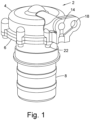
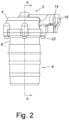
- a fuel filter 2 is comprised of a manifold 4, to which is attach a connector element 6. Reversibly connected to the connector element 6 is a filter bowl 8.
- the manifold 4 defines a fuel inlet port 14 and a fuel outlet port 18.
- the fuel inlet and outlet ports 14, 18 are provided with means (not shown) to engage with the ends of a fuel input line (not shown) and a fuel output line (not shown) respectively.
- the connector element 6 is attached to the manifold 4 by a number of bolts 22 with an annular o-ring 24 between the abutting faces of the connector element 6 and manifold 4.
- the o-ring 24 is formed of a fluorocarbon that is suitable for high temperatures and which has good chemical resistance, for example Viton (Registered trade mark) GLT which is available from DuPont Performance Elastomers. This is also the material used in connection with other annular seals, in particular o-rings, and other seal means employed in this and some other embodiments of a fuel filter according to the present disclosure.
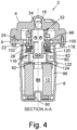
- the filter bowl 8 is adapted to reversibly engage with the connection means 6 via a helical screw thread (not shown) which is formed on the radially inner face of the portion 80 of the filter bowl 8, and the radially outer face of the portion 82 of the connector element 6.
- the filter bowl 8 is configured and dimensioned to substantially surround a known filter element 10.
- the filter element 10 has the form of a hollow cylinder and is constructed to filter fuel that is flowing radially outwardly from an inlet filter chamber 84 inside of the filter element 10 to an outlet filter chamber 86 outside the filter element 10.
- the base 88 of the filter bowl 8 is configured to engage with a first end of the filter element 10.
- the engagement is a push fit of the filter element 10 onto a spindle 90.
- the push fit is sufficiently tight that fuel will not flow through the joint between the filter element 10 and the spindle 90.
- the push fit holds the filter element 10 in position within the filter bowl 8 when the filter bowl 8 is being connected to and disconnected from the connector element 6.
- the manifold 4 defines an inlet passage 16 which extends from the fuel inlet port 14 to a mouth 104 on a face of a part of the manifold 4 that faces toward the filter bowl 8 when it is connected to the connector element 6.
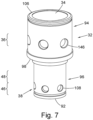
- the conduit element 32 is has a first end 106 which defines the input mouth 34, a closed end 92, and is comprised of first and second tube elements 94, 96 between the first and second ends 106, 92.
- the first tube element 94 includes first end 106 and has a larger external diameter than the second tube element 96.
- the second tube element 96 includes the second conduit end 92 and is joined to the first tube element 94 at its other end.
- Each tube element 94, 96 has approximately the same wall thickness.
- the joint between the first and second tube elements 94, 96 is a step joint forming a shoulder and a bearing face 98.
- the conduit element is held in position relative to the manifold 4 by a ring nut 100 so that the input mouth 34 of the conduit element overlies the mouth 104 of the inlet passage 16 with the result that the inside of the conduit element 32 is in fluid communication with the inlet passage 16.
- the ring nut 100 has an external thread (not shown) which engages with an internal thread 148 on a face of a second portion 102 of the connector element 6. Tightening of the ring nut 100 causes the nut to bear upon bearing face 98 of the conduit element 32 and impels the first end 106 of the conduit element 32 against the manifold 4.
- the joint between the first end 106 and the manifold 4 may include a seal means (not shown) to prevent fuel leaking out of the inlet passage 16 or conduit element 32 via that joint.
- the output mouth 38 Adjacent to the closed end 92 of the conduit element 32 is the output mouth 38 in the form of a number of apertures 108 (only one of which is labelled for clarity).
- the apertures extend through the tube 96 of the conduit element 32 and open into a void 110.
- the void 110 is in fluid communication with the inlet filter chamber 84.
- the void 110 is defined by a part of the conduit element 32, a part of the shutoff valve and a part of the second end 112 of the filter element 10.
- the second end 112 of the filter element 10 is an end cap to the portion of the filter element 10 that is comprised of a filter material and is overlaid by a layer of suitable sealing material 114.
- the shut off valve comprises a valve element 116, first and second surface portions 46, 48 of the conduit element 32, and a biasing means 28.
- the valve element 116 comprises a first valve face 118, a second valve face 120, a valve spacer 122 and a filter element abutment face 124.
- the valve spacer 122 of the valve element 116 is longitudinally extending with first and second spacer ends 134, 124.
- a first portion 136 of the valve spacer 122 extends longitudinally from the first spacer end 134 to an intermediate position 140 and the first portion 136 has the first valve face 118 as one of its faces.
- the first valve face 118 defines a cylindrical void with a first internal diameter sufficiently similar to the external diameter of the tube element 96 of the conduit element 32 for the first valve face to be a sliding fit over the outer surface of the tube element 96 of the conduit element 32.
- a second portion 138 of the valve spacer 122 extends between the intermediate position 140 and the second spacer end 124 and has a second internal diameter.
- the second internal diameter is larger than the first internal diameter of the first valve face 118.
- the second spacer end of the valve spacer 122 is the filter end abutment face 124.
- the length of the valve spacer 122 is such that when the filter bowl 8 with a filter element 10 mounted within the filter bowl 8 is fully connected to the connector element 6, the filter end abutment face 124 abuts the sealing material 114 on the second end 112 of the filter element 10, and the first valve face 118 overlies the second surface portion 48 of the conduit element 32.
- the biasing means 28 impels the valve element 116 towards the filter element 10 and as a result the filter end abutment face 124, the sealing material 114, and the second end 112 of the filter element 10 form a fuel tight joint. This has the result that while the relief valve is in its closed configuration fuel pumped into the inlet passage 16 via the inlet port 14 passes along that passage, along the conduit element 32 and out of that element via the apertures 108, into the void 110 and then into the inlet filter chamber 84. The fuel then passes through the filter portion of the filter element 10 and into the outlet filter chamber 86.
- the outlet filter chamber 86 is defined by the radially outer face of the filter element 10, a portion of the inner face of the filter bowl 8, a part of the radially outer face of the valve spacer 122, a portion of the inner face of the connector element 6, and a face of an outlet passage plate 126.
- the portion of the inner face of the connector element 6, and the face of an outlet passage plate 126 also form walls to outlet passage 120.
- the outlet passage plate 126 extends across at least part of the interface of the outlet passage 20 with the outlet filter chamber 86.
- the outlet passage plate 126 extends in the direction of the radially outer face of the valve spacer 122 from a first edge that is fixed to or integral with a portion of the connector element 6 towards a second edge 132 of the plate 126.
- the second edge 132 of the plate 126 is not attached to any wall and is spaced from the radially outer face of the valve spacer 122.
- the gap between that edge 132 and the face of the valve spacer 122 is the passage 128.
- the portion of the valve element 116 which defines the second valve face 120 of the valve element 116 is a flange 142.
- the flange 142 extends into the outlet passage 20 downstream of the outlet passage plate 126 and passage 128.
- the second valve face 120 is the face of the flange 142 that faces toward the passage 128.
- the flange 142 is so dimensioned and positioned on the valve element 116 that when the shutoff valve is in its closed position at least the outer edge 144 of the flange 142 and / or a portion of the second valve face 120 overlies and is contact with a part of the downstream face of the outlet passage plate 126. That contact is a fuel tight contact and may be assisted by the use of one or more seal means (not shown).
- the tube portion 94 of the conduit element 32 includes the relief mouth 36.
- the relief mouth 36 is a number of apertures 146 (only one labelled for clarity) which pass through the tube portion 94 and partially open into the relief chamber 62.
- the relief chamber 62 is defined by side walls 66, a first end wall 68 and a second end wall 70.
- One of the side walls 66 is the outer face of a portion of the tube 94 of the conduit element 32.
- the side wall 66 on the opposite side of the relief chamber includes a number of relief passages 64 which open at one end into the relief chamber 62 through a mouth 154 and at the other end into the outlet passage 20.
- a relief valve body 72 Within the relief chamber 62 is located a relief valve body 72. That body 72 has a pressure face 74 facing toward the relief chamber first end wall 68, a biasing face 78 facing toward the relief chamber second end wall 70, and as many relief valve faces 76 as there are relief chamber side walls 66. Each relief valve face 76 is in sliding contact with a relief chamber side wall 66.
- the relief valve body 72 is biased by biasing means 30 against a stop 150.
- the stop 150 is located in such a position that when the relief valve body 72 is biased against it, each mouth 154 is closed by a relief valve face 76.
- each of the apertures 146 in the tube 94 of the conduit element 32 are partially closed by a relief valve face 76.
- the portion of the apertures 146 that is not closed by a relief valve face 76 opens into the portion of the relief chamber 62 between the pressure face 74 of relief valve body 72 and the first end wall 68 of the relief chamber.
- fuel filling that portion of the relief chamber 62 is in communication with fuel in the inlet passage 16 and at the same pressure as that fuel.
- the portion of the relief chamber 62 between the biasing face 78 and the second end wall 70 of the relief chamber is, when the fuel filter 2 is in use, full of fuel which is in communication with fuel in the outlet passage 20 via a passage 152 extending between the part of the relief chamber 62 between the biasing face 78 and the second end wall 70 and the outlet passage 20.
- the filter element 10 becomes blocked and as a result ceases to allow the passage of sufficient fuel from the filter inlet chamber 84 to the fuel outlet chamber 86 the pumping of fuel into the fuel filter 2 by a fuel pump in the normal operation of an engine will result in an increase in the pressure of the fuel in the inlet passage 16 and hence in the part of the relief chamber 62 between the pressure face 74 and the first end wall 68.
- the bias of the biasing means 30 will be overcome and the relief valve body 72 impelled towards the second end wall 70. This will increase the proportion of the apertures 146 that are not closed by a relief valve face 76 and open each mouth 154 allowing the flow of fuel from the inlet passage 16 through the relief chamber 64 and into the outlet passage 20.
Landscapes
- Engineering & Computer Science (AREA)
- Chemical & Material Sciences (AREA)
- Chemical Kinetics & Catalysis (AREA)
- Combustion & Propulsion (AREA)
- Mechanical Engineering (AREA)
- General Engineering & Computer Science (AREA)
- Filtration Of Liquid (AREA)
- Fuel-Injection Apparatus (AREA)
Claims (15)
- Filtre à carburant (2) comprenant un collecteur (4), un élément connecteur (6), un bol filtrant (8), un élément filtrant (10), une vanne d'arrêt, un orifice d'entrée (14), un passage d'entrée (16), un orifice de sortie (18), un passage de sortie (20) et une vanne de décharge dans lequel l'élément connecteur (6) est fixé au collecteur (4), et le bol filtrant (8) est fixée de manière réversible à l'élément connecteur (6),le bol filtrant (8) est conçue pour recevoir de manière réversible l'élément filtrant (10) et est configurée de sorte que lorsque l'élément filtrant (10) est situé à l'intérieur du bol filtrant (8) et que le bol filtrant (8) est fixé à l'élément connecteur (6), l'élément filtrant (10) divise l'espace défini par l'élément connecteur (6) et le bol filtrant (8) en une chambre de filtre d'entrée (84) et une chambre de filtre de sortie (86),l'orifice d'entrée (14) est incorporé dans le collecteur (4), et l'orifice d'entrée (14) et la chambre de filtre d'entrée (84) sont en communication fluidique à travers le passage d'entrée (16),l'orifice de sortie (18) est incorporé dans le collecteur (4) et l'orifice de sortie (18) et la chambre de filtre de sortie (86) sont en communication fluidique à travers le passage de sortie (20),la vanne d'arrêt est sollicitée par un moyen de sollicitation dans une configuration fermée qui empêche le carburant de s'écouler le long des passages d'entrée et de sortie (16, 18) lorsque le bol filtrant (8) dans lequel se trouve un élément filtrant (10) n'est pas connecté à l'élément connecteur (6), et la connexion du bol filtrant (8) dans lequel se trouve un élément filtrant (10) avec l'élément connecteur (6) amène la vanne d'arrêt à être poussée dans une configuration ouverte qui permet au carburant de s'écouler le long de l'entrée et des passages de sortie (16, 18),la vanne de décharge est sollicitée par un moyen de sollicitation dans une configuration fermée dans laquelle le carburant circulant entre le passage d'entrée (16) et le passage de sortie (20) passe à travers l'élément filtrant (10), et le mouvement de la vanne de décharge dans une configuration ouverte permet au carburant de s'écouler entre le passage d'entrée (16) et le passage de sortie (20) sans que le carburant ne traverse l'élément filtrant (10), etla vanne de décharge est amenée à se déplacer dans sa configuration ouverte lorsqu'une pression de carburant prédéterminée est atteinte dans le passage d'entrée (16).
- Filtre à carburant (2) selon la revendication 1, dans lequel le filtre à carburant (2) comprend en outre un élément de conduit (32), dans lequel l'élément de conduit (32) s'étend longitudinalement et définit une embouchure d'entrée (34), une embouchure de décharge (36) et une embouchure de sortie (38), dans lequel chaque bouche (34, 36, 38) est composée d'une ou plusieurs ouvertures (108, 146) définies par une ou plusieurs parois de l'élément de conduit (32),le passage d'entrée (16) est en communication fluidique avec l'embouchure d'entrée (34) de l'élément de conduit (32), et la chambre de filtre d'entrée (84) est en communication fluidique avec l'embouchure de sortie (38) de l'élément de conduit (32), la vanne d'arrêt comprend un élément de vanne (116) qui comprend une première face de vanne (118) et une face de butée de l'élément filtrant (124),la vanne d'arrêt est dimensionnée et configurée de sorte que dans sa configuration fermée, la première face de vanne (118) recouvre une première partie de surface (46) de la surface externe de l'élément de conduit (32) qui définit l'embouchure de sortie (38) de l'élément de conduit, et dans sa configuration ouverte, la première face de vanne (118) recouvre une seconde partie de surface (48) de la surface externe de l'élément de conduit (32) qui est adjacente à la première partie de surface (46),la vanne d'arrêt est en outre dimensionnée et configurée de sorte que la face de butée de l'élément filtrant (124) vient en butée contre une partie de l'élément filtrant (10) lorsque le bol filtrant (8) dans lequel se trouve un élément filtrant (10) est connecté à l'élément de connecteur (6), etla butée de la face de butée de l'élément filtrant (124) et de l'élément filtrant (10) pousse la vanne d'arrêt dans sa configuration ouverte.
- Filtre à carburant (2) selon la revendication 2 dans lequel une première extrémité de l'élément de conduit (32) est ouverte et définit l'embouchure d'entrée (34), la seconde extrémité de l'élément de conduit (32) est fermée, les première et secondes parties de surface (46, 48) de l'élément de conduit (32) sont des parties de la paroi latérale de l'élément de conduit (32), la première partie de surface (46) est adjacente à la seconde extrémité de l'élément de conduit (32), la première partie de surface (46) se situe entre la seconde partie de surface (48) et la seconde extrémité de l'élément de conduit (32), et la partie longitudinale de l'élément de conduit (32) qui comprend les première et seconde parties de surface (46, 48) est un cylindre creux à extrémité fermée (92).
- Filtre à carburant (2) selon la revendication 3, dans lequel l'élément de conduit (32) est constitué d'un ou plusieurs cylindres creux coaxiaux réunis bout à bout si l'élément de conduit (32) est constitué de deux ou de plusieurs cylindres creux coaxiaux.
- Filtre à carburant (2) selon la revendication 3 ou 4, dans lequel l'élément de vanne (116) définit un vide cylindrique traversant l'élément de vanne (116) et la première face de vanne (118) est la face cylindrique définissant ce vide.
- Filtre à carburant (2) selon l'une quelconque des revendications 2 à 5, dans lequel l'élément de vanne (116) comprend en outre une seconde face de vanne (120), et la seconde face de vanne (120) empêche l'écoulement de carburant le long du passage de sortie (20) lorsque la vanne d'arrêt est dans sa configuration fermée, et permet l'écoulement du carburant le long du passage de sortie (20) lorsque la vanne d'arrêt est dans sa configuration ouverte.
- Filtre à carburant (2) selon la revendication 6 dans lequel le passage de sortie (20) comprend une plaque (126) et un ou plusieurs passages à plaques (128),la plaque (126) est fixée à au moins une paroi du passage de sortie (20), et présente au moins un bord libre qui n'est pas fixé à une paroi du passage de sortie (20),au moins un passage de plaque (128) est défini par au moins un bord libre de la plaque (126) et une partie d'au moins une paroi du passage de sortie (20),la plaque (126) s'étend sur une partie du passage de sortie (20) et chaque passage de plaque (128) permet l'écoulement du carburant le long du passage de sortie (20),la seconde face de vanne (120) est dimensionnée et configurée pour recouvrir une embouchure (130) de chaque passage de plaque (128) lorsque la vanne d'arrêt est dans sa configuration fermée, etla seconde face de vanne (120) est espacée d'une embouchure (130) de chaque passage de plaque lorsque la vanne d'arrêt est dans sa configuration ouverte.
- Filtre à carburant (2) selon la revendication 6 dans lequel le passage de sortie (20) comprend une plaque (126) et un ou plusieurs passages à plaques (128),chaque passage de plaque (128) s'étend à travers la plaque (126), la plaque (126) s'étend sur au moins une partie du passage de sortie (20),les passages à plaques (128) permettent l'écoulement du carburant le long du passage de sortie (20),la seconde face de vanne (120) est dimensionnée et configurée pour recouvrir une embouchure (130) de chaque passage de plaque (128) lorsque la vanne d'arrêt est dans sa configuration fermée, etla seconde face de vanne (120) est espacée d'une embouchure (154) de chaque passage de plaque (128) lorsque la vanne d'arrêt est dans sa configuration ouverte.
- Filtre à carburant (2) selon l'une quelconque des revendications 2 à 8, qui comprend en outre une chambre de décharge (62),au moins un passage de décharge (64) débouche dans la chambre de décharge (62) à travers au moins une paroi de la chambre de décharge (62),la chambre de décharge (62) est en communication fluidique avec le passage de sortie (20) à travers chaque passage de décharge (64),l'embouchure de décharge (36) de l'élément de conduit (32) débouche dans la chambre de décharge (62),la vanne de décharge (62) est composée d'un moyen de sollicitation (30) et d'un corps de vanne de décharge (72),le corps de vanne de décharge (72) est situé à l'intérieur de la chambre de décharge (62) et peut se déplacer entre une configuration fermée dans laquelle il recouvre de manière étanche les embouchures (154) de chaque passage de décharge (64), et une configuration ouverte dans laquelle les embouchures ( 154) de chaque passage de décharge (64) sont ouverts et le carburant peut s'écouler à travers chaque embouchure (154).
- Filtre à carburant (2) selon la revendication 9, dans lequel la chambre de décharge (62) est définie par au moins une paroi latérale (66), et des première et seconde parois d'extrémité (68, 70), chaque paroi latérale (66) étant parallèle à la paroi latérale (66) du côté opposé de la chambre de décharge (62), chaque passage de décharge (64) débouche dans la chambre de décharge (62) à travers une ou plusieurs des parois latérales (66),le corps de vanne de décharge (72) comprend une face de pression (74), au moins une face de vanne de décharge (76) et une face de sollicitation (78),la face de pression (74) s'étend entre chaque paroi latérale (66) de la chambre de décharge (62) et est tournée vers la première paroi d'extrémité (68) de la chambre,chaque face de vanne de décharge (76) est en contact coulissant avec une paroi latérale (66) de la chambre de décharge (62),la face de sollicitation (78) s'étend entre chaque paroi latérale (66) de la chambre de décharge (62) et est tournée vers la seconde paroi d'extrémité (70) de la chambre de décharge (62),le moyen de sollicitation (30) s'étend entre la seconde paroi d'extrémité (70) de la chambre de décharge (62) et la face de sollicitation (78) du corps de vanne de décharge (72), etl'embouchure de décharge (36) de l'élément de conduit (32) débouche au moins partiellement dans la partie de la chambre de décharge (62) entre la première paroi d'extrémité (68) de la chambre de décharge (62) et la face de pression (74) du corps de vanne de décharge (72) et/ou à travers la première paroi d'extrémité (68) de la chambre de décharge (62).
- Filtre à carburant (2) selon la revendication 10, dans lequel le corps de vanne de décharge (72) est sollicité vers une position dans laquelle la face de pression (74) du corps de vanne de décharge (72) est à une distance prédéterminée de la première paroi d'extrémité (68) de la chambre de décharge (62), l'embouchure de décharge (36) de l'élément de conduit (32) s'ouvre partiellement dans la partie de la chambre de décharge (62) entre la première paroi d'extrémité (68) de la chambre de décharge (62) et la face de pression (74) du corps de vanne de décharge (72), et
l'embouchure de décharge (36) de l'élément de conduit (32) est partiellement fermée par au moins une face de vanne de décharge (76) du corps de vanne de décharge (72). - Filtre à carburant (2) selon la revendication 11, dans lequel le corps de vanne de décharge (72) est sollicité contre un moyen d'arrêt (150).
- Filtre à carburant (2) selon l'une quelconque des revendications 1 à 12, dans lequel au moins l'un des moyens de sollicitation (30) est un ressort de compression.
- Moteur à turbine à gaz comprenant un réservoir de carburant, au moins une conduite d'alimentation en carburant, au moins un filtre à carburant (2) et une chambre de combustion dans lequel au moins un filtre à carburant (2) est un filtre à carburant (2) selon l'une quelconque des revendications 1 à 13.
- Procédé d'alimentation en carburant d'une chambre de combustion d'un moteur à turbine à gaz comprenant le passage du carburant à travers un filtre à carburant (2) selon l'une quelconque des revendications 1 à 13 avant l'introduction du carburant dans la chambre de combustion.
Applications Claiming Priority (1)
| Application Number | Priority Date | Filing Date | Title |
|---|---|---|---|
| PL43371520 | 2020-04-28 |
Publications (2)
| Publication Number | Publication Date |
|---|---|
| EP3904667A1 EP3904667A1 (fr) | 2021-11-03 |
| EP3904667B1 true EP3904667B1 (fr) | 2024-08-14 |
Family
ID=74947213
Family Applications (1)
| Application Number | Title | Priority Date | Filing Date |
|---|---|---|---|
| EP21163218.7A Active EP3904667B1 (fr) | 2020-04-28 | 2021-03-17 | Ensemble filtre à carburant |
Country Status (2)
| Country | Link |
|---|---|
| US (1) | US11692519B2 (fr) |
| EP (1) | EP3904667B1 (fr) |
Families Citing this family (8)
| Publication number | Priority date | Publication date | Assignee | Title |
|---|---|---|---|---|
| EP3907397B1 (fr) * | 2020-03-30 | 2023-06-07 | Hamilton Sundstrand Corporation | Ensemble filtres à carburant |
| EP3907398B1 (fr) | 2020-03-30 | 2023-05-03 | Hamilton Sundstrand Corporation | Ensemble filtre à carburant |
| EP3907396B1 (fr) | 2020-03-30 | 2023-06-07 | Hamilton Sundstrand Corporation | Ensemble filtre à carburant |
| USD981546S1 (en) * | 2021-04-26 | 2023-03-21 | Bissell Inc. | Filter for a floor cleaner |
| CN114225494B (zh) * | 2022-01-05 | 2023-02-28 | 贵州永红航空机械有限责任公司 | 一种流量适应型自清洁燃油滤 |
| US11724219B2 (en) | 2022-01-13 | 2023-08-15 | Deere & Company | Bypass valve with variable filter |
| USD1019886S1 (en) * | 2023-11-23 | 2024-03-26 | Chenghao Zhuang | Filter element |
| USD1093549S1 (en) * | 2025-06-10 | 2025-09-16 | Wuxi Shengsu Technology Co., Ltd. | Pet water fountain filter |
Citations (1)
| Publication number | Priority date | Publication date | Assignee | Title |
|---|---|---|---|---|
| EP3907396A1 (fr) * | 2020-03-30 | 2021-11-10 | Hamilton Sundstrand Corporation | Ensemble filtre à carburant |
Family Cites Families (34)
| Publication number | Priority date | Publication date | Assignee | Title |
|---|---|---|---|---|
| US3235085A (en) | 1962-01-08 | 1966-02-15 | Wix Corp | Filter unit having dual purpose valve assembly |
| US4053410A (en) | 1975-09-10 | 1977-10-11 | Caterpillar Tractor Co. | Filter assembly with modulating bypass valve |
| US4127484A (en) | 1977-09-09 | 1978-11-28 | Purolator, Inc. | Filter relief valve assembly |
| GB2120568B (en) | 1982-05-25 | 1985-12-24 | Lucas Ind Plc | Fuel filter |
| US4617116A (en) | 1984-05-04 | 1986-10-14 | Ford Motor Company | Automotive type fuel feed system |
| US4818397A (en) | 1986-12-22 | 1989-04-04 | Sundstrand Corporation | Shut-off valve seal |
| IT1205804B (it) | 1987-04-13 | 1989-03-31 | Ital Idee Srl | Filtro multiplo per olio lubrificante per motori a combustione interna con organo di controllo del grado di intasamento della superficie filtrante |
| US4876857A (en) | 1988-08-15 | 1989-10-31 | Allied-Signal Inc. | Shut off/pressure regulating valve for turbine engine |
| DE4310492A1 (de) | 1993-03-31 | 1994-10-06 | Hydac Filtertechnik Gmbh | Filtervorrichtung mit Keyportanschluß |
| US6113781A (en) | 1993-09-15 | 2000-09-05 | Parker-Hannifin Corporation | Fuel filter with dual flow |
| US6068762A (en) | 1995-09-29 | 2000-05-30 | Parker-Hannifin Corporation | Reusable oil filter assembly |
| US6068763A (en) | 1997-09-12 | 2000-05-30 | Purolator Products Company | Spin-on oil filter with replaceable element |
| US5881699A (en) | 1997-12-22 | 1999-03-16 | Ford Global Technologies, Inc. | Diesel fuel recirculating manifold |
| DE29915844U1 (de) | 1999-09-09 | 2001-01-25 | Ing. Walter Hengst GmbH & Co KG, 48147 Münster | Filter mit Ventil-Kombinationsbauteil |
| US6555000B2 (en) | 1999-12-03 | 2003-04-29 | Parker-Hannifin Corporation | Fuel filter with bypass valve |
| US20030127384A1 (en) * | 2002-01-09 | 2003-07-10 | Desh Kapur | Filter module for aircraft lubrication systems |
| DE10213939A1 (de) | 2002-03-28 | 2003-10-09 | Mann & Hummel Filter | Ventilanordnung, insbesondere für den Schmierölkreislauf einer Brennkraftmaschine |
| DE10315052A1 (de) * | 2002-04-03 | 2003-12-11 | Kyosan Denki Kk | Kraftstoffzuführsystem |
| JP4922923B2 (ja) | 2004-04-13 | 2012-04-25 | ドナルドソン カンパニー,インコーポレイティド | 液体ろ過用のフィルタ・カートリッジ |
| DE102004024466A1 (de) | 2004-05-14 | 2005-12-08 | Mann + Hummel Gmbh | Kraftstoffmodul |
| US7744758B2 (en) | 2005-02-15 | 2010-06-29 | Mann + Hummel Gmbh | Liquid filter |
| US8316880B2 (en) | 2009-05-08 | 2012-11-27 | Hamilton Sundstrand Corporation | Oil filter bypass valve assembly for a generator |
| ITMI20111315A1 (it) * | 2011-07-15 | 2013-01-16 | Acl S R L | Apparecchiatura filtrante |
| FR2979387B1 (fr) * | 2011-08-31 | 2017-02-10 | Snecma | Circuit de carburant dans une turbomachine |
| US9453462B2 (en) | 2012-08-31 | 2016-09-27 | Hamilton Sundstrand Corporation | Filter bypass valve |
| DE202014104029U1 (de) | 2014-08-28 | 2014-10-20 | Hengst Se & Co. Kg | Filter, der an einem Anschlussflansch anbaubar ist, und Filtereinsatz |
| US9441598B2 (en) | 2013-11-08 | 2016-09-13 | Honeywell International Inc. | Aircraft fuel filter impending and actual bypass indication system |
| DE102013223352A1 (de) | 2013-11-15 | 2015-05-21 | Mahle International Gmbh | Flüssigkeitsfilter |
| US10024239B2 (en) | 2015-07-22 | 2018-07-17 | Pratt & Whitney Canada Corp. | Fuel filter and bypass valve arrangement |
| DE102018221261A1 (de) | 2018-12-07 | 2020-06-10 | Mahle International Gmbh | Baugruppe für eine Filtereinrichtung sowie Filtereinrichtung mit einer solchen Baugruppe |
| DE102019109388A1 (de) | 2019-04-10 | 2020-10-15 | Mann+Hummel Gmbh | Rezirkulationsmodul und Kraftstoffvorfiltereinheit |
| EP3907398B1 (fr) | 2020-03-30 | 2023-05-03 | Hamilton Sundstrand Corporation | Ensemble filtre à carburant |
| EP3907397B1 (fr) | 2020-03-30 | 2023-06-07 | Hamilton Sundstrand Corporation | Ensemble filtres à carburant |
| EP4015814B1 (fr) | 2020-12-17 | 2024-08-14 | Collins Engine Nozzles, Inc. | Ensemble filtre à carburant |
-
2021
- 2021-03-17 EP EP21163218.7A patent/EP3904667B1/fr active Active
- 2021-04-26 US US17/239,843 patent/US11692519B2/en active Active
Patent Citations (1)
| Publication number | Priority date | Publication date | Assignee | Title |
|---|---|---|---|---|
| EP3907396A1 (fr) * | 2020-03-30 | 2021-11-10 | Hamilton Sundstrand Corporation | Ensemble filtre à carburant |
Also Published As
| Publication number | Publication date |
|---|---|
| EP3904667A1 (fr) | 2021-11-03 |
| US20210332779A1 (en) | 2021-10-28 |
| US11692519B2 (en) | 2023-07-04 |
Similar Documents
| Publication | Publication Date | Title |
|---|---|---|
| EP3904667B1 (fr) | Ensemble filtre à carburant | |
| EP3907396B1 (fr) | Ensemble filtre à carburant | |
| EP4015814B1 (fr) | Ensemble filtre à carburant | |
| US5698093A (en) | Gasoline filter with automatic shut off | |
| CN109416151B (zh) | 储罐阀 | |
| KR100960910B1 (ko) | 유체 매체용 펌프, 특히 디젤 연료로 작동되는 내연기관에서 수동으로 사용되는 펌프 | |
| AU2007202188B2 (en) | A hydraulic control valve in the form of a cartridge | |
| US12128337B2 (en) | Fuel filter assembly | |
| US20040154302A1 (en) | Nozzle assembly with flow divider and ecology valve | |
| RU2414640C2 (ru) | Блок манифольда бака | |
| EP3907397B1 (fr) | Ensemble filtres à carburant | |
| JP3790778B2 (ja) | 自動調整弁装置 | |
| ES2984167T3 (es) | Ensamblaje piloto ampliable para reguladores de presión | |
| CN101198814A (zh) | 用于燃油系统的双止回阀 | |
| US20200406171A1 (en) | Differential pressure valve & filter system incorporating same | |
| EP0150619A2 (fr) | Valve pour la distribution de l'écoulement | |
| US6306292B1 (en) | Fuel filter with internal pressure regulator | |
| JPH03249336A (ja) | 流体連結装置 | |
| US4159025A (en) | Back flow preventer valve | |
| CN100511065C (zh) | 减压阀和气体用调节器 | |
| US6601565B2 (en) | Pressure regulating valve and system | |
| US20050029172A1 (en) | Filter head and burner system incorporating same | |
| CN105142751A (zh) | 球形接触球接头型泄流滑阀 | |
| JPH10122162A (ja) | 圧力調整弁付き容積形ポンプ | |
| KR102935342B1 (ko) | 유량 조절 기능을 갖춘 연료유 공급 장치 |
Legal Events
| Date | Code | Title | Description |
|---|---|---|---|
| PUAI | Public reference made under article 153(3) epc to a published international application that has entered the european phase |
Free format text: ORIGINAL CODE: 0009012 |
|
| STAA | Information on the status of an ep patent application or granted ep patent |
Free format text: STATUS: THE APPLICATION HAS BEEN PUBLISHED |
|
| AK | Designated contracting states |
Kind code of ref document: A1 Designated state(s): AL AT BE BG CH CY CZ DE DK EE ES FI FR GB GR HR HU IE IS IT LI LT LU LV MC MK MT NL NO PL PT RO RS SE SI SK SM TR |
|
| B565 | Issuance of search results under rule 164(2) epc |
Effective date: 20210923 |
|
| STAA | Information on the status of an ep patent application or granted ep patent |
Free format text: STATUS: REQUEST FOR EXAMINATION WAS MADE |
|
| 17P | Request for examination filed |
Effective date: 20220427 |
|
| RBV | Designated contracting states (corrected) |
Designated state(s): AL AT BE BG CH CY CZ DE DK EE ES FI FR GB GR HR HU IE IS IT LI LT LU LV MC MK MT NL NO PL PT RO RS SE SI SK SM TR |
|
| STAA | Information on the status of an ep patent application or granted ep patent |
Free format text: STATUS: EXAMINATION IS IN PROGRESS |
|
| 17Q | First examination report despatched |
Effective date: 20221004 |
|
| GRAP | Despatch of communication of intention to grant a patent |
Free format text: ORIGINAL CODE: EPIDOSNIGR1 |
|
| STAA | Information on the status of an ep patent application or granted ep patent |
Free format text: STATUS: GRANT OF PATENT IS INTENDED |
|
| INTG | Intention to grant announced |
Effective date: 20230921 |
|
| GRAJ | Information related to disapproval of communication of intention to grant by the applicant or resumption of examination proceedings by the epo deleted |
Free format text: ORIGINAL CODE: EPIDOSDIGR1 |
|
| STAA | Information on the status of an ep patent application or granted ep patent |
Free format text: STATUS: EXAMINATION IS IN PROGRESS |
|
| INTC | Intention to grant announced (deleted) | ||
| GRAP | Despatch of communication of intention to grant a patent |
Free format text: ORIGINAL CODE: EPIDOSNIGR1 |
|
| STAA | Information on the status of an ep patent application or granted ep patent |
Free format text: STATUS: GRANT OF PATENT IS INTENDED |
|
| INTG | Intention to grant announced |
Effective date: 20240312 |
|
| GRAS | Grant fee paid |
Free format text: ORIGINAL CODE: EPIDOSNIGR3 |
|
| GRAA | (expected) grant |
Free format text: ORIGINAL CODE: 0009210 |
|
| STAA | Information on the status of an ep patent application or granted ep patent |
Free format text: STATUS: THE PATENT HAS BEEN GRANTED |
|
| AK | Designated contracting states |
Kind code of ref document: B1 Designated state(s): AL AT BE BG CH CY CZ DE DK EE ES FI FR GB GR HR HU IE IS IT LI LT LU LV MC MK MT NL NO PL PT RO RS SE SI SK SM TR |
|
| REG | Reference to a national code |
Ref country code: GB Ref legal event code: FG4D |
|
| REG | Reference to a national code |
Ref country code: CH Ref legal event code: EP |
|
| REG | Reference to a national code |
Ref country code: DE Ref legal event code: R096 Ref document number: 602021017059 Country of ref document: DE |
|
| REG | Reference to a national code |
Ref country code: IE Ref legal event code: FG4D |
|
| REG | Reference to a national code |
Ref country code: LT Ref legal event code: MG9D |
|
| REG | Reference to a national code |
Ref country code: NL Ref legal event code: MP Effective date: 20240814 |
|
| PG25 | Lapsed in a contracting state [announced via postgrant information from national office to epo] |
Ref country code: NO Free format text: LAPSE BECAUSE OF FAILURE TO SUBMIT A TRANSLATION OF THE DESCRIPTION OR TO PAY THE FEE WITHIN THE PRESCRIBED TIME-LIMIT Effective date: 20241114 |
|
| REG | Reference to a national code |
Ref country code: AT Ref legal event code: MK05 Ref document number: 1713505 Country of ref document: AT Kind code of ref document: T Effective date: 20240814 |
|
| PG25 | Lapsed in a contracting state [announced via postgrant information from national office to epo] |
Ref country code: NL Free format text: LAPSE BECAUSE OF FAILURE TO SUBMIT A TRANSLATION OF THE DESCRIPTION OR TO PAY THE FEE WITHIN THE PRESCRIBED TIME-LIMIT Effective date: 20240814 Ref country code: PT Free format text: LAPSE BECAUSE OF FAILURE TO SUBMIT A TRANSLATION OF THE DESCRIPTION OR TO PAY THE FEE WITHIN THE PRESCRIBED TIME-LIMIT Effective date: 20241216 Ref country code: GR Free format text: LAPSE BECAUSE OF FAILURE TO SUBMIT A TRANSLATION OF THE DESCRIPTION OR TO PAY THE FEE WITHIN THE PRESCRIBED TIME-LIMIT Effective date: 20241115 Ref country code: PL Free format text: LAPSE BECAUSE OF FAILURE TO SUBMIT A TRANSLATION OF THE DESCRIPTION OR TO PAY THE FEE WITHIN THE PRESCRIBED TIME-LIMIT Effective date: 20240814 Ref country code: FI Free format text: LAPSE BECAUSE OF FAILURE TO SUBMIT A TRANSLATION OF THE DESCRIPTION OR TO PAY THE FEE WITHIN THE PRESCRIBED TIME-LIMIT Effective date: 20240814 |
|
| PG25 | Lapsed in a contracting state [announced via postgrant information from national office to epo] |
Ref country code: BG Free format text: LAPSE BECAUSE OF FAILURE TO SUBMIT A TRANSLATION OF THE DESCRIPTION OR TO PAY THE FEE WITHIN THE PRESCRIBED TIME-LIMIT Effective date: 20240814 |
|
| PG25 | Lapsed in a contracting state [announced via postgrant information from national office to epo] |
Ref country code: LV Free format text: LAPSE BECAUSE OF FAILURE TO SUBMIT A TRANSLATION OF THE DESCRIPTION OR TO PAY THE FEE WITHIN THE PRESCRIBED TIME-LIMIT Effective date: 20240814 |
|
| PG25 | Lapsed in a contracting state [announced via postgrant information from national office to epo] |
Ref country code: AT Free format text: LAPSE BECAUSE OF FAILURE TO SUBMIT A TRANSLATION OF THE DESCRIPTION OR TO PAY THE FEE WITHIN THE PRESCRIBED TIME-LIMIT Effective date: 20240814 Ref country code: IS Free format text: LAPSE BECAUSE OF FAILURE TO SUBMIT A TRANSLATION OF THE DESCRIPTION OR TO PAY THE FEE WITHIN THE PRESCRIBED TIME-LIMIT Effective date: 20241214 |
|
| PG25 | Lapsed in a contracting state [announced via postgrant information from national office to epo] |
Ref country code: HR Free format text: LAPSE BECAUSE OF FAILURE TO SUBMIT A TRANSLATION OF THE DESCRIPTION OR TO PAY THE FEE WITHIN THE PRESCRIBED TIME-LIMIT Effective date: 20240814 |
|
| PG25 | Lapsed in a contracting state [announced via postgrant information from national office to epo] |
Ref country code: ES Free format text: LAPSE BECAUSE OF FAILURE TO SUBMIT A TRANSLATION OF THE DESCRIPTION OR TO PAY THE FEE WITHIN THE PRESCRIBED TIME-LIMIT Effective date: 20240814 Ref country code: RS Free format text: LAPSE BECAUSE OF FAILURE TO SUBMIT A TRANSLATION OF THE DESCRIPTION OR TO PAY THE FEE WITHIN THE PRESCRIBED TIME-LIMIT Effective date: 20241114 |
|
| PG25 | Lapsed in a contracting state [announced via postgrant information from national office to epo] |
Ref country code: RS Free format text: LAPSE BECAUSE OF FAILURE TO SUBMIT A TRANSLATION OF THE DESCRIPTION OR TO PAY THE FEE WITHIN THE PRESCRIBED TIME-LIMIT Effective date: 20241114 Ref country code: PT Free format text: LAPSE BECAUSE OF FAILURE TO SUBMIT A TRANSLATION OF THE DESCRIPTION OR TO PAY THE FEE WITHIN THE PRESCRIBED TIME-LIMIT Effective date: 20241216 Ref country code: PL Free format text: LAPSE BECAUSE OF FAILURE TO SUBMIT A TRANSLATION OF THE DESCRIPTION OR TO PAY THE FEE WITHIN THE PRESCRIBED TIME-LIMIT Effective date: 20240814 Ref country code: NO Free format text: LAPSE BECAUSE OF FAILURE TO SUBMIT A TRANSLATION OF THE DESCRIPTION OR TO PAY THE FEE WITHIN THE PRESCRIBED TIME-LIMIT Effective date: 20241114 Ref country code: NL Free format text: LAPSE BECAUSE OF FAILURE TO SUBMIT A TRANSLATION OF THE DESCRIPTION OR TO PAY THE FEE WITHIN THE PRESCRIBED TIME-LIMIT Effective date: 20240814 Ref country code: LV Free format text: LAPSE BECAUSE OF FAILURE TO SUBMIT A TRANSLATION OF THE DESCRIPTION OR TO PAY THE FEE WITHIN THE PRESCRIBED TIME-LIMIT Effective date: 20240814 Ref country code: IS Free format text: LAPSE BECAUSE OF FAILURE TO SUBMIT A TRANSLATION OF THE DESCRIPTION OR TO PAY THE FEE WITHIN THE PRESCRIBED TIME-LIMIT Effective date: 20241214 Ref country code: HR Free format text: LAPSE BECAUSE OF FAILURE TO SUBMIT A TRANSLATION OF THE DESCRIPTION OR TO PAY THE FEE WITHIN THE PRESCRIBED TIME-LIMIT Effective date: 20240814 Ref country code: GR Free format text: LAPSE BECAUSE OF FAILURE TO SUBMIT A TRANSLATION OF THE DESCRIPTION OR TO PAY THE FEE WITHIN THE PRESCRIBED TIME-LIMIT Effective date: 20241115 Ref country code: FI Free format text: LAPSE BECAUSE OF FAILURE TO SUBMIT A TRANSLATION OF THE DESCRIPTION OR TO PAY THE FEE WITHIN THE PRESCRIBED TIME-LIMIT Effective date: 20240814 Ref country code: ES Free format text: LAPSE BECAUSE OF FAILURE TO SUBMIT A TRANSLATION OF THE DESCRIPTION OR TO PAY THE FEE WITHIN THE PRESCRIBED TIME-LIMIT Effective date: 20240814 Ref country code: BG Free format text: LAPSE BECAUSE OF FAILURE TO SUBMIT A TRANSLATION OF THE DESCRIPTION OR TO PAY THE FEE WITHIN THE PRESCRIBED TIME-LIMIT Effective date: 20240814 Ref country code: AT Free format text: LAPSE BECAUSE OF FAILURE TO SUBMIT A TRANSLATION OF THE DESCRIPTION OR TO PAY THE FEE WITHIN THE PRESCRIBED TIME-LIMIT Effective date: 20240814 |
|
| PG25 | Lapsed in a contracting state [announced via postgrant information from national office to epo] |
Ref country code: RO Free format text: LAPSE BECAUSE OF FAILURE TO SUBMIT A TRANSLATION OF THE DESCRIPTION OR TO PAY THE FEE WITHIN THE PRESCRIBED TIME-LIMIT Effective date: 20240814 Ref country code: SM Free format text: LAPSE BECAUSE OF FAILURE TO SUBMIT A TRANSLATION OF THE DESCRIPTION OR TO PAY THE FEE WITHIN THE PRESCRIBED TIME-LIMIT Effective date: 20240814 Ref country code: DK Free format text: LAPSE BECAUSE OF FAILURE TO SUBMIT A TRANSLATION OF THE DESCRIPTION OR TO PAY THE FEE WITHIN THE PRESCRIBED TIME-LIMIT Effective date: 20240814 |
|
| PG25 | Lapsed in a contracting state [announced via postgrant information from national office to epo] |
Ref country code: EE Free format text: LAPSE BECAUSE OF FAILURE TO SUBMIT A TRANSLATION OF THE DESCRIPTION OR TO PAY THE FEE WITHIN THE PRESCRIBED TIME-LIMIT Effective date: 20240814 |
|
| PG25 | Lapsed in a contracting state [announced via postgrant information from national office to epo] |
Ref country code: CZ Free format text: LAPSE BECAUSE OF FAILURE TO SUBMIT A TRANSLATION OF THE DESCRIPTION OR TO PAY THE FEE WITHIN THE PRESCRIBED TIME-LIMIT Effective date: 20240814 |
|
| PG25 | Lapsed in a contracting state [announced via postgrant information from national office to epo] |
Ref country code: SK Free format text: LAPSE BECAUSE OF FAILURE TO SUBMIT A TRANSLATION OF THE DESCRIPTION OR TO PAY THE FEE WITHIN THE PRESCRIBED TIME-LIMIT Effective date: 20240814 Ref country code: IT Free format text: LAPSE BECAUSE OF FAILURE TO SUBMIT A TRANSLATION OF THE DESCRIPTION OR TO PAY THE FEE WITHIN THE PRESCRIBED TIME-LIMIT Effective date: 20240814 |
|
| REG | Reference to a national code |
Ref country code: DE Ref legal event code: R097 Ref document number: 602021017059 Country of ref document: DE |
|
| PLBE | No opposition filed within time limit |
Free format text: ORIGINAL CODE: 0009261 |
|
| STAA | Information on the status of an ep patent application or granted ep patent |
Free format text: STATUS: NO OPPOSITION FILED WITHIN TIME LIMIT |
|
| 26N | No opposition filed |
Effective date: 20250515 |
|
| PG25 | Lapsed in a contracting state [announced via postgrant information from national office to epo] |
Ref country code: SE Free format text: LAPSE BECAUSE OF FAILURE TO SUBMIT A TRANSLATION OF THE DESCRIPTION OR TO PAY THE FEE WITHIN THE PRESCRIBED TIME-LIMIT Effective date: 20240814 |
|
| PG25 | Lapsed in a contracting state [announced via postgrant information from national office to epo] |
Ref country code: MC Free format text: LAPSE BECAUSE OF FAILURE TO SUBMIT A TRANSLATION OF THE DESCRIPTION OR TO PAY THE FEE WITHIN THE PRESCRIBED TIME-LIMIT Effective date: 20240814 |
|
| REG | Reference to a national code |
Ref country code: CH Ref legal event code: H13 Free format text: ST27 STATUS EVENT CODE: U-0-0-H10-H13 (AS PROVIDED BY THE NATIONAL OFFICE) Effective date: 20251023 |
|
| PG25 | Lapsed in a contracting state [announced via postgrant information from national office to epo] |
Ref country code: LU Free format text: LAPSE BECAUSE OF NON-PAYMENT OF DUE FEES Effective date: 20250317 |
|
| REG | Reference to a national code |
Ref country code: BE Ref legal event code: MM Effective date: 20250331 |
|
| PG25 | Lapsed in a contracting state [announced via postgrant information from national office to epo] |
Ref country code: BE Free format text: LAPSE BECAUSE OF NON-PAYMENT OF DUE FEES Effective date: 20250331 |
|
| PG25 | Lapsed in a contracting state [announced via postgrant information from national office to epo] |
Ref country code: CH Free format text: LAPSE BECAUSE OF NON-PAYMENT OF DUE FEES Effective date: 20250331 |
|
| PG25 | Lapsed in a contracting state [announced via postgrant information from national office to epo] |
Ref country code: IE Free format text: LAPSE BECAUSE OF NON-PAYMENT OF DUE FEES Effective date: 20250317 |
|
| PGFP | Annual fee paid to national office [announced via postgrant information from national office to epo] |
Ref country code: GB Payment date: 20260220 Year of fee payment: 6 |
|
| PGFP | Annual fee paid to national office [announced via postgrant information from national office to epo] |
Ref country code: DE Payment date: 20260219 Year of fee payment: 6 |
|
| PGFP | Annual fee paid to national office [announced via postgrant information from national office to epo] |
Ref country code: FR Payment date: 20260220 Year of fee payment: 6 |