EP3904676B1 - Grease collection arrangement - Google Patents
Grease collection arrangement Download PDFInfo
- Publication number
- EP3904676B1 EP3904676B1 EP20171473.0A EP20171473A EP3904676B1 EP 3904676 B1 EP3904676 B1 EP 3904676B1 EP 20171473 A EP20171473 A EP 20171473A EP 3904676 B1 EP3904676 B1 EP 3904676B1
- Authority
- EP
- European Patent Office
- Prior art keywords
- grease
- extraction
- bearing
- collection arrangement
- chamber
- Prior art date
- Legal status (The legal status is an assumption and is not a legal conclusion. Google has not performed a legal analysis and makes no representation as to the accuracy of the status listed.)
- Active
Links
Images

Classifications
-
- F—MECHANICAL ENGINEERING; LIGHTING; HEATING; WEAPONS; BLASTING
- F16—ENGINEERING ELEMENTS AND UNITS; GENERAL MEASURES FOR PRODUCING AND MAINTAINING EFFECTIVE FUNCTIONING OF MACHINES OR INSTALLATIONS; THERMAL INSULATION IN GENERAL
- F16N—LUBRICATING
- F16N31/00—Means for collecting, retaining, or draining-off lubricant in or on machines or apparatus
-
- F—MECHANICAL ENGINEERING; LIGHTING; HEATING; WEAPONS; BLASTING
- F03—MACHINES OR ENGINES FOR LIQUIDS; WIND, SPRING, OR WEIGHT MOTORS; PRODUCING MECHANICAL POWER OR A REACTIVE PROPULSIVE THRUST, NOT OTHERWISE PROVIDED FOR
- F03D—WIND MOTORS
- F03D80/00—Details, components or accessories not provided for in groups F03D1/00 - F03D17/00
- F03D80/70—Bearing or lubricating arrangements
-
- F—MECHANICAL ENGINEERING; LIGHTING; HEATING; WEAPONS; BLASTING
- F16—ENGINEERING ELEMENTS AND UNITS; GENERAL MEASURES FOR PRODUCING AND MAINTAINING EFFECTIVE FUNCTIONING OF MACHINES OR INSTALLATIONS; THERMAL INSULATION IN GENERAL
- F16N—LUBRICATING
- F16N31/00—Means for collecting, retaining, or draining-off lubricant in or on machines or apparatus
- F16N31/02—Oil catchers; Oil wipers
-
- F—MECHANICAL ENGINEERING; LIGHTING; HEATING; WEAPONS; BLASTING
- F16—ENGINEERING ELEMENTS AND UNITS; GENERAL MEASURES FOR PRODUCING AND MAINTAINING EFFECTIVE FUNCTIONING OF MACHINES OR INSTALLATIONS; THERMAL INSULATION IN GENERAL
- F16C—SHAFTS; FLEXIBLE SHAFTS; ELEMENTS OR CRANKSHAFT MECHANISMS; ROTARY BODIES OTHER THAN GEARING ELEMENTS; BEARINGS
- F16C33/00—Parts of bearings; Special methods for making bearings or parts thereof
- F16C33/02—Parts of sliding-contact bearings
- F16C33/04—Brasses; Bushes; Linings
- F16C33/06—Sliding surface mainly made of metal
- F16C33/10—Construction relative to lubrication
- F16C33/102—Construction relative to lubrication with grease as lubricant
-
- F—MECHANICAL ENGINEERING; LIGHTING; HEATING; WEAPONS; BLASTING
- F16—ENGINEERING ELEMENTS AND UNITS; GENERAL MEASURES FOR PRODUCING AND MAINTAINING EFFECTIVE FUNCTIONING OF MACHINES OR INSTALLATIONS; THERMAL INSULATION IN GENERAL
- F16C—SHAFTS; FLEXIBLE SHAFTS; ELEMENTS OR CRANKSHAFT MECHANISMS; ROTARY BODIES OTHER THAN GEARING ELEMENTS; BEARINGS
- F16C33/00—Parts of bearings; Special methods for making bearings or parts thereof
- F16C33/30—Parts of ball or roller bearings
- F16C33/66—Special parts or details in view of lubrication
- F16C33/6603—Special parts or details in view of lubrication with grease as lubricant
- F16C33/6622—Details of supply and/or removal of the grease, e.g. purging grease
-
- F—MECHANICAL ENGINEERING; LIGHTING; HEATING; WEAPONS; BLASTING
- F16—ENGINEERING ELEMENTS AND UNITS; GENERAL MEASURES FOR PRODUCING AND MAINTAINING EFFECTIVE FUNCTIONING OF MACHINES OR INSTALLATIONS; THERMAL INSULATION IN GENERAL
- F16N—LUBRICATING
- F16N29/00—Special means in lubricating arrangements or systems providing for the indication or detection of undesired conditions; Use of devices responsive to conditions in lubricating arrangements or systems
-
- F—MECHANICAL ENGINEERING; LIGHTING; HEATING; WEAPONS; BLASTING
- F16—ENGINEERING ELEMENTS AND UNITS; GENERAL MEASURES FOR PRODUCING AND MAINTAINING EFFECTIVE FUNCTIONING OF MACHINES OR INSTALLATIONS; THERMAL INSULATION IN GENERAL
- F16C—SHAFTS; FLEXIBLE SHAFTS; ELEMENTS OR CRANKSHAFT MECHANISMS; ROTARY BODIES OTHER THAN GEARING ELEMENTS; BEARINGS
- F16C2360/00—Engines or pumps
- F16C2360/31—Wind motors
-
- F—MECHANICAL ENGINEERING; LIGHTING; HEATING; WEAPONS; BLASTING
- F16—ENGINEERING ELEMENTS AND UNITS; GENERAL MEASURES FOR PRODUCING AND MAINTAINING EFFECTIVE FUNCTIONING OF MACHINES OR INSTALLATIONS; THERMAL INSULATION IN GENERAL
- F16N—LUBRICATING
- F16N2210/00—Applications
- F16N2210/02—Turbines
- F16N2210/025—Wind Turbines
-
- F—MECHANICAL ENGINEERING; LIGHTING; HEATING; WEAPONS; BLASTING
- F16—ENGINEERING ELEMENTS AND UNITS; GENERAL MEASURES FOR PRODUCING AND MAINTAINING EFFECTIVE FUNCTIONING OF MACHINES OR INSTALLATIONS; THERMAL INSULATION IN GENERAL
- F16N—LUBRICATING
- F16N2210/00—Applications
- F16N2210/14—Bearings
-
- F—MECHANICAL ENGINEERING; LIGHTING; HEATING; WEAPONS; BLASTING
- F16—ENGINEERING ELEMENTS AND UNITS; GENERAL MEASURES FOR PRODUCING AND MAINTAINING EFFECTIVE FUNCTIONING OF MACHINES OR INSTALLATIONS; THERMAL INSULATION IN GENERAL
- F16N—LUBRICATING
- F16N2280/00—Valves
-
- Y—GENERAL TAGGING OF NEW TECHNOLOGICAL DEVELOPMENTS; GENERAL TAGGING OF CROSS-SECTIONAL TECHNOLOGIES SPANNING OVER SEVERAL SECTIONS OF THE IPC; TECHNICAL SUBJECTS COVERED BY FORMER USPC CROSS-REFERENCE ART COLLECTIONS [XRACs] AND DIGESTS
- Y02—TECHNOLOGIES OR APPLICATIONS FOR MITIGATION OR ADAPTATION AGAINST CLIMATE CHANGE
- Y02E—REDUCTION OF GREENHOUSE GAS [GHG] EMISSIONS, RELATED TO ENERGY GENERATION, TRANSMISSION OR DISTRIBUTION
- Y02E10/00—Energy generation through renewable energy sources
- Y02E10/70—Wind energy
- Y02E10/72—Wind turbines with rotation axis in wind direction
Definitions
- pitch bearing Most large wind turbines have rotor blades that can be pitched about their long axes.
- the circular root end of a rotor blade terminates at a pitch bearing.
- a pitch system actuates one or more drive motors in response to a command from the wind turbine controller to pitch the rotor blade by a determined angular amount.
- a reliable lubrication of the pitch bearing is very important for various reasons. Damage to a pitch bearing can result in wind turbine downtime, with the attendant reduction in annual energy production. The reliability of the pitch bearings is particularly relevant in the case of an offshore wind turbine because service routines are expensive and hazardous.
- a rotor blade of a large wind turbine can have a length in the region of 90 m, a mass in the region of 50000 kg and a root end diameter in the order of 5 m.
- the pitch bearing of such a large rotor blade may be realised as a roller bearing, a ball bearing, a slider bearing, etc.
- the stationary part and the rotating part of the bearing are separated at all times by a film of oil or grease. Since lubricant deteriorates over time, a pitch bearing is generally equipped with a lubricant system which is able to replenish the lubricant as required.
- Various lubrication systems are available, and most systems include a grease reservoir and one or more feeder lines to grease inlets of the bearing. Controlled quantities of grease are fed at intervals into the bearing.
- a pump station delivers lubricant through a single supply line to a lubricant metering device serving a single lubrication point.
- a pitch bearing of a large rotor blade can have several such lubrication points.
- lubricant is continually transported to various lubrication points as long as the lubricant pump is running.
- the pistons of a metering device will also stop, and will "hold" their positions.
- the pump starts supplying lubricant again, the metering device pistons resume from those positions.
- the lubricant points are distributed evenly about a rotor blade pitch bearing, and this symmetry is reflected in the waste grease collection.
- a wind turbine rotor blade is not pitched about its entire 360°, and is generally only pitched within a narrower range, e.g. over 90°. This leads to a problem of waste grease "pooling" in certain parts of the lubrication system.
- the grease collection arrangement comprises a plurality of grease extraction valves, wherein each grease extraction valve is connected to a grease outlet of the bearing; an extraction circuit comprising a waste grease line extending between each grease extraction valve and a common extraction line leading to a single grease depository; a vacuum apparatus configured to create an under-pressure in the extraction lines; and a valve controller configured to selectively open and close a grease extraction valve.
- the grease extraction is essentially independent of the grease supply system, i.e. the grease extraction events are independent of grease injection events.
- a further advantage of the inventive grease collection arrangement is that, because the valve controller can selectively open and close the grease extraction valves, waste grease is selectively extracted, i.e. the waste grease will only be sucked through a grease extraction valve that is open.
- a further significant advantage is that the grease depository can be realised as a single container, or a single container assembly, positioned at an easily accessible location. This is because the extraction circuit is "fed" by all grease extraction valves, and the waste grease lines all feed to the common extraction line.
- the method of collecting waste grease from a bearing lubrication circuit using such a grease collection arrangement comprises the steps of closing the grease extraction valves; operating the vacuum apparatus to lower the pressure in the extraction lines; and opening a grease extraction valve to allow passage of waste grease into the extraction line and from there into the common extraction line.
- the cycle can be repeated at regular intervals, or as required.
- the arrangement of extraction lines feeding to the common extraction line may be referred to in the following as the "extraction circuit".
- a wind turbine rotor blade pitch assembly comprises a pitch bearing at an interface between the rotor blade root end and a hub of the wind turbine.
- the pitch assembly further comprises a lubrication system that is configured to deliver lubricant grease through a bearing lubrication circuit to grease inlets of the bearing.
- the pitch assembly further comprises an embodiment of the inventive grease collector arrangement for extracting waste grease from grease outlets of the bearing.
- An advantage of the inventive rotor blade pitch assembly is that the waste grease is extracted more reliably from the bearing. Furthermore, since the waste grease is collected in a single depository, collection of the waste grease for disposal purposes can be carried out more quickly and with less effort, compared to the known systems which can require that a technician enter a crawl space to gain access to multiple small grease containers.
- the rotor blade pitch assembly is for a large wind turbine, i.e. a wind turbine with rotor blades having a length in the order of 90 m and a root end diameter in the order of 5 m.
- the vacuum system controller is configured to selectively actuate each grease extraction valve between its open position and its closed position.
- the controller can actuate each valve independently of the other grease extraction valves, and/or the controller can actuate two or more grease extraction valves simultaneously.
- the vacuum apparatus comprises a vacuum pump configured to create a vacuum or under-pressure in the extraction circuit. This can be done by closing all grease extraction valves and running the vacuum pump until the pressure in the extraction lines has reduced to a maximum threshold level, preferably to a level of at most 90% of the ambient pressure (e.g. 900 mbar when ambient pressure is 1 bar), more preferably at most 85% of the ambient pressure (e.g. 850 mbar when ambient pressure is 1 bar).
- the effect of such a low pressure in the extraction circuit is that, as soon as a grease extraction valve is opened, any waste grease will be sucked into the extraction line.
- the "strength" of the under-pressure can be chosen according to the viscosity of the waste grease.
- the inventive grease collection arrangement preferably comprises a two-part vacuum chamber to route the waste grease into a depository.
- the vacuum chamber is arranged between the common extraction line and the vacuum pump, and comprises a first chamber, a second chamber, and a membrane or diaphragm to separate the first chamber from the second chamber.
- the first chamber comprises an inlet fed by the common extraction line, and an outlet leading to a grease depository; in other words the first chamber is arranged between the common extraction line and the grease depository.
- the second chamber is connected to the vacuum pump.
- the membrane dividing the vacuum chamber allows an under-pressure to develop in the extraction circuit.
- the lubrication system of a rotor blade pitch bearing is generally constructed to distribute grease evenly throughout the bearing, but grease can "pool" in specific regions of the bearing on account of the nature of the pitching process. Therefore, in a preferred embodiment of the invention, the method comprises a step of identifying which grease extraction valve may be positioned in a critical region of the bearing. Such a critical region can be determined on the basis of experience, for example. Any such grease extraction valve can be addressed more frequently to ensure that all waste grease is reliably extracted.
- the quantity of grease that is extracted should be monitored so that the level of grease in the depository can be estimated for timely scheduling of a collection and disposal procedure. Equally, monitoring of the extracted quantity of grease can help to identify a potential problem in the lubricant system, or to identify a critical "pooling" region of the bearing as mentioned above.
- a flow-meter is arranged between the common collection point and the vacuum chamber. The flow-meter measures the quantity of extracted grease. The data collected and reported by the flow-meter can be reported back to a control centre and/or recorded for readout during a service routine.
- the grease collection arrangement comprises at least four grease extraction valves, more preferably at least six grease extraction valves.
- the number of grease extraction valves may be chosen according to the bearing design. For example, a large pitch bearing as described above can have an inner stationary race with 20 or more grease outlets, with each outlet connected to a grease extraction valve.
- the lubrication system is a progressive lubrication system, since a progressive system is more reliable than a single-line system and will continue feeding grease to the bearing as required.
- the grease depository can be a container with a volume of 5000 ml or more and is preferably arranged in an easily accessible location, for example at an easily accessible position in the hub interior.
- Figure 1 shows an embodiment of the inventive grease collection arrangement 1.
- the diagram indicates a rotor blade pitch bearing 2 with a number of grease outlets 20 through which lubricant grease can be removed.
- the grease collection arrangement 1 comprises a number of individually controllable grease extraction valves 10V, one at each grease outlet 20. Each grease extraction valve 10V is connected to a waste line 10L, and these all feed into a common line 10N.
- the common line 10N leads to a waste grease container 15, via one chamber 12A of a vacuum chamber module 12.
- Only four grease outlets 20 are shown in the diagram for the sake of clarity, and therefore only four grease extraction valves 10V and waste lines 10L, but it shall be understood that the stationary race of a large pitch bearing may be provided with 20 - 30 such grease outlets 20, and the inventive grease collection arrangement 1 will also have a corresponding number of grease extraction valves 10V and waste lines 10L.
- Each grease extraction valve 10V is controlled by a signal 13-1, 13-2, ..., 13-n issued by a control module 13. While all grease extraction valves 10V are closed, the control module 13 actuates a pump 11 that progressively withdraws air from the common line 10N and the waste lines 10L, via the second chamber 12B of the vacuum chamber module 12.
- valve 16 When the pressure in the extraction circuit has been reduced to a desired low level, valve 16 is closed in order to maintain the under-pressure in the chamber 12.
- a selected grease extraction valve 10V is opened by issuing an appropriate control signal. For example, the grease extraction valve 10V on the right side of the bearing 2 in the diagram is opened by signal 13-1.
- valve 17 is opened. Any waste grease at the outlet 20 of the selected grease extraction valve 10V will be sucked into the common line 10N by the underpressure at the vacuum chamber 12.
- Waste grease in the common line 10N passes through the first chamber 12A to the grease container 15.
- a membrane 12M ensures that grease remains on the one side of the vacuum chamber module 12.
- valve 17 is closed, and valve 18 is opened.
- the vacuum pump 11 then alters its running direction in order to generate an overpressure in the primary chamber 12A, with the result that the waste grease is forced out of the primary chamber 12A and into the waste grease reservoir 15.
- the diagram also shows a flow-meter 14 arranged in the common line 10N.
- the flow-meter 14 measures the quantity of extracted grease.
- the data collected and reported by the flow-meter 14 can be reported back to a control centre and/or recorded for readout during a service routine.
- FIG. 2 shows components of a progressive lubrication system 3 which can be used to provide lubricant grease to a device such as a rotor blade pitch bearing (not shown).
- Lubricant grease is provided in a reservoir pump unit 30 that pumps the grease to a primary metering device 31, which in turn distributes the grease to a number of secondary metering devices 32 (two are shown here by way of example).
- Each secondary metering device 32 has a number of outlets connected by branch lines 32-1, 32-2, ..., 32-n to grease entry points of the pitch bearing.
- the metering devices 31, 32 ensure that predetermined quantities of lubricant arrive at the grease entry points.
- the amount to be metered is determined by a control unit 33.
- Such a progressive lubrication system provides continuous lubrication when the pump is in operation. If the pump is halted, the pistons in the metering devices 31, 32 hold their positions, and resume from those positions when the pump is re-started.
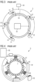
- FIG. 3 shows a prior art bearing lubrication system 5, in this case a single-line lubrication system.
- grease is provided from a grease supply 50, and a number of grease injection modules 51 are used to inject lubricant grease into a bearing 2.
- Waste grease passes from a waste outlet 52 into a common line 54 that feeds into a container 55.
- Grease collection is therefore only done when lubricant grease is replenished. If any hose of the lubricant circuit becomes faulty for any reason, the entire system is compromised and the pitch system must be halted for repair.
- Figure 4 shows another prior art single-line lubrication system 6 for a rotor blade pitch bearing.
- grease is provided from a grease supply 60, and waste grease passes from a waste outlet 62 of a single-line ejector 61 into a common line 64 that feeds into a container 65.
- the waste grease collection is driven by the amount of grease added, and waste grease is only collected when lubricant grease is replenished.
Landscapes
- Engineering & Computer Science (AREA)
- General Engineering & Computer Science (AREA)
- Mechanical Engineering (AREA)
- Life Sciences & Earth Sciences (AREA)
- Sustainable Development (AREA)
- Sustainable Energy (AREA)
- Chemical & Material Sciences (AREA)
- Combustion & Propulsion (AREA)
- Rolling Contact Bearings (AREA)
Priority Applications (5)
| Application Number | Priority Date | Filing Date | Title |
|---|---|---|---|
| EP20171473.0A EP3904676B1 (en) | 2020-04-27 | 2020-04-27 | Grease collection arrangement |
| ES20171473T ES2955732T3 (es) | 2020-04-27 | 2020-04-27 | Disposición de recolección de grasa |
| DK20171473.0T DK3904676T3 (da) | 2020-04-27 | 2020-04-27 | Fedtopsamlingsanordning |
| US17/234,956 US12038131B2 (en) | 2020-04-27 | 2021-04-20 | Grease collection arrangement |
| CN202110459309.7A CN113639182B (zh) | 2020-04-27 | 2021-04-27 | 油脂收集装置 |
Applications Claiming Priority (1)
| Application Number | Priority Date | Filing Date | Title |
|---|---|---|---|
| EP20171473.0A EP3904676B1 (en) | 2020-04-27 | 2020-04-27 | Grease collection arrangement |
Publications (2)
| Publication Number | Publication Date |
|---|---|
| EP3904676A1 EP3904676A1 (en) | 2021-11-03 |
| EP3904676B1 true EP3904676B1 (en) | 2023-07-05 |
Family
ID=70483022
Family Applications (1)
| Application Number | Title | Priority Date | Filing Date |
|---|---|---|---|
| EP20171473.0A Active EP3904676B1 (en) | 2020-04-27 | 2020-04-27 | Grease collection arrangement |
Country Status (5)
| Country | Link |
|---|---|
| US (1) | US12038131B2 (da) |
| EP (1) | EP3904676B1 (da) |
| CN (1) | CN113639182B (da) |
| DK (1) | DK3904676T3 (da) |
| ES (1) | ES2955732T3 (da) |
Families Citing this family (3)
| Publication number | Priority date | Publication date | Assignee | Title |
|---|---|---|---|---|
| DE102020211264A1 (de) * | 2020-09-08 | 2022-03-10 | Aktiebolaget Skf | System zum Schmieren eines gedichteten Lagers und zugehöriges Verfahren |
| ES2951135T3 (es) * | 2020-09-25 | 2023-10-18 | Siemens Gamesa Renewable Energy As | Disposición de recogida de grasa para recoger grasa residual de un cojinete de paso de pala de rotor lubricado con grasa de una turbina eólica |
| CN114294332B (zh) * | 2022-01-10 | 2023-09-26 | 江苏大学 | 一种主轴承主动润滑及清洁控制方法及其系统 |
Family Cites Families (15)
| Publication number | Priority date | Publication date | Assignee | Title |
|---|---|---|---|---|
| US2299119A (en) * | 1939-09-09 | 1942-10-20 | Bliss E W Co | Bearing |
| US4818706A (en) * | 1983-04-19 | 1989-04-04 | American Monitor Corporation | Reagent-dispensing system and method |
| JPH03222875A (ja) * | 1991-02-06 | 1991-10-01 | Toufuku Kk | 粘性流体圧送装置 |
| CN102753820A (zh) | 2010-02-10 | 2012-10-24 | 三菱重工业株式会社 | 风力发电装置 |
| EP2754908B1 (en) * | 2013-01-10 | 2018-01-10 | GE Renewable Technologies | Lubrication systems for bearing assemblies |
| CN103591433B (zh) | 2013-11-08 | 2016-05-18 | 青岛盘古润滑技术有限公司 | 一种废油脂主动回收装置及集中润滑系统以及回收方法 |
| CN205137028U (zh) | 2015-11-23 | 2016-04-06 | 龙源(北京)风电工程技术有限公司 | 风电机组变桨轴承油脂加注器具及含有该器具的变桨轴承 |
| US10316856B2 (en) * | 2015-12-01 | 2019-06-11 | General Electric Company | Casing for use in a turbofan engine and method of scavenging fluid therefrom |
| CN105972418A (zh) * | 2016-06-02 | 2016-09-28 | 湘电风能有限公司 | 一种轴承自动润滑与废脂收集系统 |
| DK3312493T3 (da) | 2016-10-18 | 2020-04-14 | Siemens Gamesa Renewable Energy As | Smøremiddelbeholder |
| EP3318790B1 (en) | 2016-11-04 | 2019-10-02 | Siemens Gamesa Renewable Energy A/S | Grease filter |
| CN107701902A (zh) * | 2017-09-29 | 2018-02-16 | 郑州奥特科技有限公司 | 轴承废油脂自动收集系统及轴承自动换脂系统 |
| CN109404708A (zh) | 2018-12-19 | 2019-03-01 | 国电联合动力技术有限公司 | 用于潮流能机组的智能轴承润滑系统及其机组、控制方法 |
| CN210319352U (zh) * | 2019-08-09 | 2020-04-14 | 湘电风能有限公司 | 一种轴承智能润滑与废油回收系统 |
| CN110513594A (zh) * | 2019-08-23 | 2019-11-29 | 舍弗勒技术股份两合公司 | 轴承单元及轴承排脂装置 |
-
2020
- 2020-04-27 EP EP20171473.0A patent/EP3904676B1/en active Active
- 2020-04-27 DK DK20171473.0T patent/DK3904676T3/da active
- 2020-04-27 ES ES20171473T patent/ES2955732T3/es active Active
-
2021
- 2021-04-20 US US17/234,956 patent/US12038131B2/en active Active
- 2021-04-27 CN CN202110459309.7A patent/CN113639182B/zh active Active
Also Published As
| Publication number | Publication date |
|---|---|
| ES2955732T3 (es) | 2023-12-05 |
| US12038131B2 (en) | 2024-07-16 |
| EP3904676A1 (en) | 2021-11-03 |
| DK3904676T3 (da) | 2023-08-21 |
| CN113639182A (zh) | 2021-11-12 |
| CN113639182B (zh) | 2023-10-10 |
| US20210332944A1 (en) | 2021-10-28 |
Similar Documents
| Publication | Publication Date | Title |
|---|---|---|
| EP3904676B1 (en) | Grease collection arrangement | |
| US8221075B2 (en) | Systems and method for operating a wind turbine having active flow control | |
| US11619210B2 (en) | Gearbox system for a wind turbine, wind turbine with a gearbox system, and method for operating a gearbox system | |
| US8480362B2 (en) | Method for dynamically lubricating a wind turbine pitch blade bearing | |
| EP1749976B1 (en) | Gas turbine comprising a washing device | |
| EP2535576A1 (en) | Wind power generation device | |
| EP3332103B1 (en) | Lubrication systems for transmissions | |
| US11828269B2 (en) | Grease collection arrangement for collecting waste grease from a grease lubricated rotor blade pitch bearing of a wind turbine | |
| CN108869205A (zh) | 一种风电机组发电机轴承自动润滑智能控制系统及方法 | |
| US11885311B2 (en) | Lubrication system | |
| CN218760265U (zh) | 一种风电主轴轴承润滑系统 | |
| CN108953077B (zh) | 润滑系统、润滑方法及风力发电机组 | |
| DE102020112724A1 (de) | System zur Energiespeicherung und -rückgewinnung | |
| WO2020104420A1 (de) | Vorrichtung zur entgasung von flüssigkeiten | |
| CN222296499U (zh) | 罗茨机械设备的自润滑控制装置、罗茨机械设备 | |
| CN220322163U (zh) | 开式冷却塔补水装置 | |
| EP2724006B1 (de) | Luftturbinenanlage und zugehörige verfahren | |
| CN223483958U (zh) | 一种页岩气压缩机自动补油装置 | |
| DE102013007629B4 (de) | Einwechselaggregat mit einem Kleinmengenschmiermittelspender II | |
| EP3650703B1 (de) | Vakuumpumpe und verfahren zur schmierung einer solchen | |
| CN118361367A (zh) | 变桨润滑系统及其控制方法和风力发电机组 | |
| KR20110096103A (ko) | 풍력 발전 장치 | |
| CN107237369A (zh) | 一种用于二次供水系统的人机交互界面系统 |
Legal Events
| Date | Code | Title | Description |
|---|---|---|---|
| PUAI | Public reference made under article 153(3) epc to a published international application that has entered the european phase |
Free format text: ORIGINAL CODE: 0009012 |
|
| STAA | Information on the status of an ep patent application or granted ep patent |
Free format text: STATUS: THE APPLICATION HAS BEEN PUBLISHED |
|
| AK | Designated contracting states |
Kind code of ref document: A1 Designated state(s): AL AT BE BG CH CY CZ DE DK EE ES FI FR GB GR HR HU IE IS IT LI LT LU LV MC MK MT NL NO PL PT RO RS SE SI SK SM TR |
|
| B565 | Issuance of search results under rule 164(2) epc |
Effective date: 20201007 |
|
| STAA | Information on the status of an ep patent application or granted ep patent |
Free format text: STATUS: REQUEST FOR EXAMINATION WAS MADE |
|
| 17P | Request for examination filed |
Effective date: 20220503 |
|
| RBV | Designated contracting states (corrected) |
Designated state(s): AL AT BE BG CH CY CZ DE DK EE ES FI FR GB GR HR HU IE IS IT LI LT LU LV MC MK MT NL NO PL PT RO RS SE SI SK SM TR |
|
| GRAP | Despatch of communication of intention to grant a patent |
Free format text: ORIGINAL CODE: EPIDOSNIGR1 |
|
| STAA | Information on the status of an ep patent application or granted ep patent |
Free format text: STATUS: GRANT OF PATENT IS INTENDED |
|
| RIC1 | Information provided on ipc code assigned before grant |
Ipc: F16C 33/10 20060101ALI20230209BHEP Ipc: F16N 31/00 20060101ALI20230209BHEP Ipc: F03D 80/70 20160101AFI20230209BHEP |
|
| INTG | Intention to grant announced |
Effective date: 20230309 |
|
| GRAS | Grant fee paid |
Free format text: ORIGINAL CODE: EPIDOSNIGR3 |
|
| GRAA | (expected) grant |
Free format text: ORIGINAL CODE: 0009210 |
|
| STAA | Information on the status of an ep patent application or granted ep patent |
Free format text: STATUS: THE PATENT HAS BEEN GRANTED |
|
| AK | Designated contracting states |
Kind code of ref document: B1 Designated state(s): AL AT BE BG CH CY CZ DE DK EE ES FI FR GB GR HR HU IE IS IT LI LT LU LV MC MK MT NL NO PL PT RO RS SE SI SK SM TR |
|
| REG | Reference to a national code |
Ref country code: CH Ref legal event code: EP |
|
| REG | Reference to a national code |
Ref country code: AT Ref legal event code: REF Ref document number: 1585067 Country of ref document: AT Kind code of ref document: T Effective date: 20230715 |
|
| REG | Reference to a national code |
Ref country code: DE Ref legal event code: R096 Ref document number: 602020013178 Country of ref document: DE |
|
| REG | Reference to a national code |
Ref country code: IE Ref legal event code: FG4D |
|
| REG | Reference to a national code |
Ref country code: DK Ref legal event code: T3 Effective date: 20230818 |
|
| REG | Reference to a national code |
Ref country code: LT Ref legal event code: MG9D |
|
| REG | Reference to a national code |
Ref country code: NL Ref legal event code: MP Effective date: 20230705 |
|
| REG | Reference to a national code |
Ref country code: ES Ref legal event code: FG2A Ref document number: 2955732 Country of ref document: ES Kind code of ref document: T3 Effective date: 20231205 |
|
| REG | Reference to a national code |
Ref country code: AT Ref legal event code: MK05 Ref document number: 1585067 Country of ref document: AT Kind code of ref document: T Effective date: 20230705 |
|
| PG25 | Lapsed in a contracting state [announced via postgrant information from national office to epo] |
Ref country code: NL Free format text: LAPSE BECAUSE OF FAILURE TO SUBMIT A TRANSLATION OF THE DESCRIPTION OR TO PAY THE FEE WITHIN THE PRESCRIBED TIME-LIMIT Effective date: 20230705 |
|
| PG25 | Lapsed in a contracting state [announced via postgrant information from national office to epo] |
Ref country code: GR Free format text: LAPSE BECAUSE OF FAILURE TO SUBMIT A TRANSLATION OF THE DESCRIPTION OR TO PAY THE FEE WITHIN THE PRESCRIBED TIME-LIMIT Effective date: 20231006 |
|
| PG25 | Lapsed in a contracting state [announced via postgrant information from national office to epo] |
Ref country code: IS Free format text: LAPSE BECAUSE OF FAILURE TO SUBMIT A TRANSLATION OF THE DESCRIPTION OR TO PAY THE FEE WITHIN THE PRESCRIBED TIME-LIMIT Effective date: 20231105 |
|
| PG25 | Lapsed in a contracting state [announced via postgrant information from national office to epo] |
Ref country code: SE Free format text: LAPSE BECAUSE OF FAILURE TO SUBMIT A TRANSLATION OF THE DESCRIPTION OR TO PAY THE FEE WITHIN THE PRESCRIBED TIME-LIMIT Effective date: 20230705 Ref country code: RS Free format text: LAPSE BECAUSE OF FAILURE TO SUBMIT A TRANSLATION OF THE DESCRIPTION OR TO PAY THE FEE WITHIN THE PRESCRIBED TIME-LIMIT Effective date: 20230705 Ref country code: PT Free format text: LAPSE BECAUSE OF FAILURE TO SUBMIT A TRANSLATION OF THE DESCRIPTION OR TO PAY THE FEE WITHIN THE PRESCRIBED TIME-LIMIT Effective date: 20231106 Ref country code: NO Free format text: LAPSE BECAUSE OF FAILURE TO SUBMIT A TRANSLATION OF THE DESCRIPTION OR TO PAY THE FEE WITHIN THE PRESCRIBED TIME-LIMIT Effective date: 20231005 Ref country code: LV Free format text: LAPSE BECAUSE OF FAILURE TO SUBMIT A TRANSLATION OF THE DESCRIPTION OR TO PAY THE FEE WITHIN THE PRESCRIBED TIME-LIMIT Effective date: 20230705 Ref country code: LT Free format text: LAPSE BECAUSE OF FAILURE TO SUBMIT A TRANSLATION OF THE DESCRIPTION OR TO PAY THE FEE WITHIN THE PRESCRIBED TIME-LIMIT Effective date: 20230705 Ref country code: IS Free format text: LAPSE BECAUSE OF FAILURE TO SUBMIT A TRANSLATION OF THE DESCRIPTION OR TO PAY THE FEE WITHIN THE PRESCRIBED TIME-LIMIT Effective date: 20231105 Ref country code: HR Free format text: LAPSE BECAUSE OF FAILURE TO SUBMIT A TRANSLATION OF THE DESCRIPTION OR TO PAY THE FEE WITHIN THE PRESCRIBED TIME-LIMIT Effective date: 20230705 Ref country code: GR Free format text: LAPSE BECAUSE OF FAILURE TO SUBMIT A TRANSLATION OF THE DESCRIPTION OR TO PAY THE FEE WITHIN THE PRESCRIBED TIME-LIMIT Effective date: 20231006 Ref country code: FI Free format text: LAPSE BECAUSE OF FAILURE TO SUBMIT A TRANSLATION OF THE DESCRIPTION OR TO PAY THE FEE WITHIN THE PRESCRIBED TIME-LIMIT Effective date: 20230705 Ref country code: AT Free format text: LAPSE BECAUSE OF FAILURE TO SUBMIT A TRANSLATION OF THE DESCRIPTION OR TO PAY THE FEE WITHIN THE PRESCRIBED TIME-LIMIT Effective date: 20230705 |
|
| PG25 | Lapsed in a contracting state [announced via postgrant information from national office to epo] |
Ref country code: PL Free format text: LAPSE BECAUSE OF FAILURE TO SUBMIT A TRANSLATION OF THE DESCRIPTION OR TO PAY THE FEE WITHIN THE PRESCRIBED TIME-LIMIT Effective date: 20230705 |
|
| REG | Reference to a national code |
Ref country code: DE Ref legal event code: R097 Ref document number: 602020013178 Country of ref document: DE |
|
| PG25 | Lapsed in a contracting state [announced via postgrant information from national office to epo] |
Ref country code: SM Free format text: LAPSE BECAUSE OF FAILURE TO SUBMIT A TRANSLATION OF THE DESCRIPTION OR TO PAY THE FEE WITHIN THE PRESCRIBED TIME-LIMIT Effective date: 20230705 Ref country code: RO Free format text: LAPSE BECAUSE OF FAILURE TO SUBMIT A TRANSLATION OF THE DESCRIPTION OR TO PAY THE FEE WITHIN THE PRESCRIBED TIME-LIMIT Effective date: 20230705 Ref country code: EE Free format text: LAPSE BECAUSE OF FAILURE TO SUBMIT A TRANSLATION OF THE DESCRIPTION OR TO PAY THE FEE WITHIN THE PRESCRIBED TIME-LIMIT Effective date: 20230705 Ref country code: CZ Free format text: LAPSE BECAUSE OF FAILURE TO SUBMIT A TRANSLATION OF THE DESCRIPTION OR TO PAY THE FEE WITHIN THE PRESCRIBED TIME-LIMIT Effective date: 20230705 Ref country code: SK Free format text: LAPSE BECAUSE OF FAILURE TO SUBMIT A TRANSLATION OF THE DESCRIPTION OR TO PAY THE FEE WITHIN THE PRESCRIBED TIME-LIMIT Effective date: 20230705 |
|
| PLBE | No opposition filed within time limit |
Free format text: ORIGINAL CODE: 0009261 |
|
| STAA | Information on the status of an ep patent application or granted ep patent |
Free format text: STATUS: NO OPPOSITION FILED WITHIN TIME LIMIT |
|
| PG25 | Lapsed in a contracting state [announced via postgrant information from national office to epo] |
Ref country code: IT Free format text: LAPSE BECAUSE OF FAILURE TO SUBMIT A TRANSLATION OF THE DESCRIPTION OR TO PAY THE FEE WITHIN THE PRESCRIBED TIME-LIMIT Effective date: 20230705 |
|
| 26N | No opposition filed |
Effective date: 20240408 |
|
| PG25 | Lapsed in a contracting state [announced via postgrant information from national office to epo] |
Ref country code: SI Free format text: LAPSE BECAUSE OF FAILURE TO SUBMIT A TRANSLATION OF THE DESCRIPTION OR TO PAY THE FEE WITHIN THE PRESCRIBED TIME-LIMIT Effective date: 20230705 |
|
| PG25 | Lapsed in a contracting state [announced via postgrant information from national office to epo] |
Ref country code: BG Free format text: LAPSE BECAUSE OF FAILURE TO SUBMIT A TRANSLATION OF THE DESCRIPTION OR TO PAY THE FEE WITHIN THE PRESCRIBED TIME-LIMIT Effective date: 20230705 |
|
| PG25 | Lapsed in a contracting state [announced via postgrant information from national office to epo] |
Ref country code: MC Free format text: LAPSE BECAUSE OF FAILURE TO SUBMIT A TRANSLATION OF THE DESCRIPTION OR TO PAY THE FEE WITHIN THE PRESCRIBED TIME-LIMIT Effective date: 20230705 |
|
| PG25 | Lapsed in a contracting state [announced via postgrant information from national office to epo] |
Ref country code: MC Free format text: LAPSE BECAUSE OF FAILURE TO SUBMIT A TRANSLATION OF THE DESCRIPTION OR TO PAY THE FEE WITHIN THE PRESCRIBED TIME-LIMIT Effective date: 20230705 Ref country code: BG Free format text: LAPSE BECAUSE OF FAILURE TO SUBMIT A TRANSLATION OF THE DESCRIPTION OR TO PAY THE FEE WITHIN THE PRESCRIBED TIME-LIMIT Effective date: 20230705 |
|
| REG | Reference to a national code |
Ref country code: CH Ref legal event code: PL |
|
| PG25 | Lapsed in a contracting state [announced via postgrant information from national office to epo] |
Ref country code: LU Free format text: LAPSE BECAUSE OF NON-PAYMENT OF DUE FEES Effective date: 20240427 |
|
| REG | Reference to a national code |
Ref country code: BE Ref legal event code: MM Effective date: 20240430 |
|
| PG25 | Lapsed in a contracting state [announced via postgrant information from national office to epo] |
Ref country code: LU Free format text: LAPSE BECAUSE OF NON-PAYMENT OF DUE FEES Effective date: 20240427 |
|
| PG25 | Lapsed in a contracting state [announced via postgrant information from national office to epo] |
Ref country code: BE Free format text: LAPSE BECAUSE OF NON-PAYMENT OF DUE FEES Effective date: 20240430 |
|
| PG25 | Lapsed in a contracting state [announced via postgrant information from national office to epo] |
Ref country code: BE Free format text: LAPSE BECAUSE OF NON-PAYMENT OF DUE FEES Effective date: 20240430 Ref country code: CH Free format text: LAPSE BECAUSE OF NON-PAYMENT OF DUE FEES Effective date: 20240430 |
|
| PG25 | Lapsed in a contracting state [announced via postgrant information from national office to epo] |
Ref country code: IE Free format text: LAPSE BECAUSE OF NON-PAYMENT OF DUE FEES Effective date: 20240427 |
|
| PGFP | Annual fee paid to national office [announced via postgrant information from national office to epo] |
Ref country code: DE Payment date: 20250428 Year of fee payment: 6 |
|
| PGFP | Annual fee paid to national office [announced via postgrant information from national office to epo] |
Ref country code: DK Payment date: 20250424 Year of fee payment: 6 Ref country code: ES Payment date: 20250513 Year of fee payment: 6 |
|
| PGFP | Annual fee paid to national office [announced via postgrant information from national office to epo] |
Ref country code: FR Payment date: 20250424 Year of fee payment: 6 |
|
| PG25 | Lapsed in a contracting state [announced via postgrant information from national office to epo] |
Ref country code: CY Free format text: LAPSE BECAUSE OF FAILURE TO SUBMIT A TRANSLATION OF THE DESCRIPTION OR TO PAY THE FEE WITHIN THE PRESCRIBED TIME-LIMIT; INVALID AB INITIO Effective date: 20200427 |
|
| PG25 | Lapsed in a contracting state [announced via postgrant information from national office to epo] |
Ref country code: HU Free format text: LAPSE BECAUSE OF FAILURE TO SUBMIT A TRANSLATION OF THE DESCRIPTION OR TO PAY THE FEE WITHIN THE PRESCRIBED TIME-LIMIT; INVALID AB INITIO Effective date: 20200427 |
|
| PGFP | Annual fee paid to national office [announced via postgrant information from national office to epo] |
Ref country code: GB Payment date: 20260323 Year of fee payment: 7 |