EP3904686A1 - Verdrängerpumpe - Google Patents
Verdrängerpumpe Download PDFInfo
- Publication number
- EP3904686A1 EP3904686A1 EP20171964.8A EP20171964A EP3904686A1 EP 3904686 A1 EP3904686 A1 EP 3904686A1 EP 20171964 A EP20171964 A EP 20171964A EP 3904686 A1 EP3904686 A1 EP 3904686A1
- Authority
- EP
- European Patent Office
- Prior art keywords
- stator housing
- coupling
- eccentric piston
- eccentric
- coupling part
- Prior art date
- Legal status (The legal status is an assumption and is not a legal conclusion. Google has not performed a legal analysis and makes no representation as to the accuracy of the status listed.)
- Granted
Links
Images

Classifications
-
- F—MECHANICAL ENGINEERING; LIGHTING; HEATING; WEAPONS; BLASTING
- F04—POSITIVE - DISPLACEMENT MACHINES FOR LIQUIDS; PUMPS FOR LIQUIDS OR ELASTIC FLUIDS
- F04C—ROTARY-PISTON, OR OSCILLATING-PISTON, POSITIVE-DISPLACEMENT MACHINES FOR LIQUIDS; ROTARY-PISTON, OR OSCILLATING-PISTON, POSITIVE-DISPLACEMENT PUMPS
- F04C2/00—Rotary-piston machines or pumps
- F04C2/02—Rotary-piston machines or pumps of arcuate-engagement type, i.e. with circular translatory movement of co-operating members, each member having the same number of teeth or tooth-equivalents
-
- F—MECHANICAL ENGINEERING; LIGHTING; HEATING; WEAPONS; BLASTING
- F01—MACHINES OR ENGINES IN GENERAL; ENGINE PLANTS IN GENERAL; STEAM ENGINES
- F01C—ROTARY-PISTON OR OSCILLATING-PISTON MACHINES OR ENGINES
- F01C17/00—Arrangements for drive of co-operating members, e.g. for rotary piston and casing
- F01C17/06—Arrangements for drive of co-operating members, e.g. for rotary piston and casing using cranks, universal joints or similar elements
- F01C17/066—Arrangements for drive of co-operating members, e.g. for rotary piston and casing using cranks, universal joints or similar elements with an intermediate piece sliding along perpendicular axes, e.g. Oldham coupling
-
- F—MECHANICAL ENGINEERING; LIGHTING; HEATING; WEAPONS; BLASTING
- F04—POSITIVE - DISPLACEMENT MACHINES FOR LIQUIDS; PUMPS FOR LIQUIDS OR ELASTIC FLUIDS
- F04C—ROTARY-PISTON, OR OSCILLATING-PISTON, POSITIVE-DISPLACEMENT MACHINES FOR LIQUIDS; ROTARY-PISTON, OR OSCILLATING-PISTON, POSITIVE-DISPLACEMENT PUMPS
- F04C15/00—Component parts, details or accessories of machines, pumps or pumping installations, not provided for in groups F04C2/00 - F04C14/00
- F04C15/0057—Driving elements, brakes, couplings, transmission specially adapted for machines or pumps
- F04C15/0061—Means for transmitting movement from the prime mover to driven parts of the pump, e.g. clutches, couplings, transmissions
- F04C15/0065—Means for transmitting movement from the prime mover to driven parts of the pump, e.g. clutches, couplings, transmissions for eccentric movement
-
- F—MECHANICAL ENGINEERING; LIGHTING; HEATING; WEAPONS; BLASTING
- F04—POSITIVE - DISPLACEMENT MACHINES FOR LIQUIDS; PUMPS FOR LIQUIDS OR ELASTIC FLUIDS
- F04C—ROTARY-PISTON, OR OSCILLATING-PISTON, POSITIVE-DISPLACEMENT MACHINES FOR LIQUIDS; ROTARY-PISTON, OR OSCILLATING-PISTON, POSITIVE-DISPLACEMENT PUMPS
- F04C15/00—Component parts, details or accessories of machines, pumps or pumping installations, not provided for in groups F04C2/00 - F04C14/00
- F04C15/0057—Driving elements, brakes, couplings, transmission specially adapted for machines or pumps
- F04C15/0061—Means for transmitting movement from the prime mover to driven parts of the pump, e.g. clutches, couplings, transmissions
- F04C15/0073—Couplings between rotors and input or output shafts acting by interengaging or mating parts, i.e. positive coupling of rotor and shaft
-
- F—MECHANICAL ENGINEERING; LIGHTING; HEATING; WEAPONS; BLASTING
- F04—POSITIVE - DISPLACEMENT MACHINES FOR LIQUIDS; PUMPS FOR LIQUIDS OR ELASTIC FLUIDS
- F04C—ROTARY-PISTON, OR OSCILLATING-PISTON, POSITIVE-DISPLACEMENT MACHINES FOR LIQUIDS; ROTARY-PISTON, OR OSCILLATING-PISTON, POSITIVE-DISPLACEMENT PUMPS
- F04C2/00—Rotary-piston machines or pumps
- F04C2/02—Rotary-piston machines or pumps of arcuate-engagement type, i.e. with circular translatory movement of co-operating members, each member having the same number of teeth or tooth-equivalents
- F04C2/04—Rotary-piston machines or pumps of arcuate-engagement type, i.e. with circular translatory movement of co-operating members, each member having the same number of teeth or tooth-equivalents of internal axis type
- F04C2/045—Rotary-piston machines or pumps of arcuate-engagement type, i.e. with circular translatory movement of co-operating members, each member having the same number of teeth or tooth-equivalents of internal axis type having a C-shaped piston
Definitions
- the invention relates to a positive displacement pump.
- a displacement pump has a stator housing and an eccentric piston.
- the eccentric piston follows a circular path relative to the stator housing.
- the eccentric piston is secured against rotation relative to the stator housing by means of an anti-twist device.
- this anti-rotation device must not block the relative movement between the eccentric piston and the stator housing on the circular path.
- At least one pump chamber is formed between the stator housing and the eccentric piston. The volume of the pump chamber changes with the movement of the eccentric piston along the circular path, whereby the delivery of the fluid can be brought about by the positive displacement pump.
- DE 697 14 935 T2 discloses a displacement pump of the type explained at the outset, in which the anti-rotation device is designed as a two-part corrugated tube which supports the eccentric piston on the starter housing.
- the torsional rigidity of the corrugated tube ensures the security with regard to a relative rotation between the eccentric piston and the stator housing.
- the corrugated tube is designed to be flexible about a transverse axis and axially compressible, which enables the relative movement between the eccentric piston and the stator housing on the circular path.
- the anti-rotation device is designed as a driver coupling.
- the eccentric piston is secured with regard to a rotation with respect to the stator housing via the Installation of drivers of coupling parts of the driver coupling in the circumferential direction. There is thus a related securing by a form fit of the driver in the circumferential direction. A very stiff securing against the relative rotation can thus take place.
- the relative rotational position of the eccentric piston with respect to the stator housing can also be specified very precisely by the design of the drivers of the coupling parts.
- the required relative movement between the eccentric piston and the stator housing on the circular path is made possible by a relative movement of the drivers, which can be a relative sliding movement, for example.
- This relative movement therefore does not require any elastic loading of an elastic element, as would be the case if a corrugated pipe was used to prevent rotation.
- this driver coupling there are various possibilities within the scope of the invention, provided that this driver coupling on the one hand enables the protection against rotation and on the other hand enables the relative movement on the circular path.
- this driver coupling can be designed as a cross-slot coupling or cross slide coupling or so-called “Oldham” coupling, cf. in this regard, for example, the entry on "Oldham coupling” under Wikipedia (date of inspection : 04/22/2020).
- the driver coupling has three coupling parts.
- a first coupling part is formed by the stator housing or (directly or indirectly) held on it.
- a second coupling part is formed by the eccentric piston or (directly or indirectly) held on it.
- a third coupling part is arranged between the first coupling part and the second coupling part.
- the third coupling part is mounted pivotably about a first transverse axis on the first coupling part or on the second coupling part.
- the storage also ensures an axial displacement along the first transverse axis.
- the third coupling part is also mounted displaceably in the direction of a second transverse axis on the other of the first coupling part and the second coupling part.
- first transverse axis and the second transverse axis are oriented orthogonally to one another.
- the relative movement between the stator housing and the eccentric piston (and thus between the first coupling part and the second coupling part) on a circular path can be ensured on the one hand by the displaceability along the first transverse axis and on the other hand by the displaceability in the direction of the second transverse axis.
- the Pivotability about a first transverse axis possibly also an adjustment of the inclination.
- the driver coupling has an axial degree of freedom, which for the use of the aforementioned coupling parts can mean that the first coupling part is axially displaceable with respect to the third coupling part.
- This axial degree of freedom can be ensured, for example, between the third coupling part and the other of the first and second coupling parts by simultaneously ensuring the displaceability in the direction of the second transverse axis and the displaceability in the direction of the axial degree of freedom.
- the third coupling part is a coupling disc.
- the clutch disk can have two radial slots which are arranged offset from one another in the circumferential direction by 180 degrees in the circumferential direction and are thus arranged on opposite sides of the clutch disk.
- the clutch disc also has two pivot pins.
- the pivot pins are arranged offset from one another by 180 degrees in the circumferential direction and are thus arranged on opposite sides of the clutch disc.
- the pivot pins are arranged coaxially to one another.
- the pivot pins are offset by 90 degrees in the circumferential direction with respect to the aforementioned slots.
- the slots on the one hand and the pivot pins on the other hand are thus provided on the clutch disc in accordance with an X or in the form of a cross.
- the driver formed by the eccentric piston or held thereon (directly or indirectly) is mounted rotatably about the longitudinal axis of the pivot pin.
- the additional degree of freedom of displacement can then be ensured in a particularly simple manner in that this driver is mounted such that it can be displaced in the longitudinal direction of the pivot pin with respect to the pivot pin.
- the driver can have a bearing eye or a bearing bore through which the pivot pin extends, whereby the degree of freedom of rotation and the degree of freedom of displacement can be provided in a simple but reliable manner at the same time.
- two drivers formed by the stator or held thereon (directly or indirectly) are guided displaceably in the radial direction and / or in the axial direction in the slots.
- the boundaries of the slots form driver surfaces on which corresponding driver surfaces of the driver formed by the stator housing or held thereon for contact come.
- the displacement in the radial direction and / or in the axial direction can then be ensured by means of a relative sliding movement of the driver surfaces.
- a corrugated pipe or a torsionally rigid bellows are not (exclusively) used for the anti-twist protection. It is entirely possible, however, that in addition to the measures mentioned, a bellows is also used in a displacement pump according to the invention, via which the stator housing and the eccentric piston are then additionally connected. It is also possible to use a torsion-soft bellows, which can then serve exclusively or primarily for a required seal, but at the same time enables the necessary relative movements.
- the bellows can be made of any material within the scope of the invention.
- a bellows is preferably made from plastic. It is possible that the bellows is made of a polymer material, in particular a PTFE.
- Fig. 1 shows a positive displacement pump 1 in the area of a pump part 2 in a cross section II (with regard to the section, cf. Fig. 2 ).
- a stator housing 5 is held on a housing 3, here a housing cover 4.
- the stator housing 5 has a basically hollow-cylindrical stator housing outer part 6 as well as a stator housing inner part 7, which is likewise embodied in the form of a hollow cylinder.
- the stator housing outer part 6 and the stator housing inner part 7 are designed and arranged concentrically to a drive axis 8.
- the stator housing outer part 6 is firmly connected to the stator housing inner part 7 via a web 9 that runs approximately radially here.
- a hollow-cylindrical receiving space 10 oriented coaxially to the drive axis 4 is formed between the outer part 6 of the stator housing and the inner part 7 of the stator housing. Adjacent to the web 9 in one circumferential direction, a connection channel 11 is formed in the stator housing outer part 6, while the stator housing inner part 7 is provided on the side of the web 9 arranged in the other circumferential direction, a connection channel 32 and the stator housing inner part 7 a slot or an opening 12 is formed here.
- An eccentric piston 13 has an eccentric piston outer part 14 and an eccentric piston inner part 15, which have an annular body 33 (cf. Fig. 2 ) are firmly connected to each other.
- the eccentric piston outer part 14 is designed as a hollow cylinder and has a slot or an opening 16 through which the web 9 of the stator housing 5 extends.
- the eccentric piston inner part 15 has a cylindrical outer surface 17 and is also designed as a hollow cylinder for the illustrated embodiment.
- the eccentric piston outer part 14 and the jacket surface 17 of the eccentric piston inner part 15 are arranged concentrically to an eccentric axis 18 which has an eccentricity 19 with respect to the drive axis 8.
- the eccentric axis 18 (and with it the eccentric piston 13) moves on a circular path 20 around the drive axis 8
- Connecting gap 21 is formed with an inner surface 22 of the stator housing inner part 7.
- a jacket surface 23 of the stator housing inner part 7 rests on the side opposite the eccentricity in a sealing area 25 on an inner surface 24 of the stator housing outer part 6, while on the opposite in the circumferential direction Side, that is, in the direction of the eccentricity, between the lateral surface 23 of the stator housing inner part 7 and the inner surface 24 of the eccentric piston outer part Gap is formed with a gap height that is continuously changed in between.
- a jacket surface 30 of the eccentric piston outer part 14 in the direction of eccentricity forms a sealing area 26 with an inner surface 27 of the stator housing outer part 6, while these have a maximum distance on the opposite side in the circumferential direction, with the distance between them continuously changing in the circumferential direction .
- a pump chamber 28 is formed between the stator housing outer part 6 and the eccentric piston outer part 14, which is sealed in a peripheral end area by the sealing area 26 limited pump chamber 29 is formed.
- the pumping effect of the positive displacement pump 1 is exemplified for a direction of movement 31 of the eccentric piston 13 on the circular path 20 clockwise in FIG Fig. 1 explained:
- the pump chamber 28 can be filled with a fluid to be conveyed via the connection channel 11. If the sealing area 26 is moved in front of the connection channel 11 in the direction of movement 31, the sealing area 26 closes the connection between the connection channel 11 and the pump chamber 28, while the pump chamber 28 is connected to a connection channel 32.
- the volume of the pump chamber 28 decreases, since the circumferential distance of the sealing area 26 from the connection channel 32 decreases. The pump chamber 28 thus pushes the fluid arranged therein out of the connection channel 32.
- the pump chamber 29 If its sealing area 25 is located behind the opening 16 in the direction of movement 31, the pump chamber 29 can also be filled with fluid from the connection channel 11. In the operating position according to Fig. 1 has the Sealing area 25 has already been displaced upwards, the pump chamber 29 arranged in front of the sealing area 25 in the direction of movement 31 having already reduced its volume in such a way that fluid from the pump chamber 29 can also be pushed out of the connection channel 32.
- the pump chambers 28, 29 are arranged in the circumferential direction on opposite sides, so that they alternately suck in fluid and push it out, whereby a delivery rate that is largely independent of the movement in the direction of movement 31 can be achieved. It is possible that the displacement pump 1 works reversibly, so that a reverse pumping effect can be achieved when the direction of movement 31 is reversed.
- a chamber formed between the inner surface 22 of the stator housing inner part 7 and the jacket surface 17 of the eccentric piston inner part 15 is preferably not involved in providing the conveying capacity.
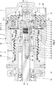
- Fig. 2 is the further embodiment of the pump part 2 of the positive displacement pump 1 in a longitudinal section (with regard to the section, cf. II-II in Fig. 1 ) shown.
- the stator housing 5 forms a semi-longitudinal section corresponding to a lying U, the side legs of the lying U forming the stator housing outer part 6 and the stator housing inner part 7 and the base leg U being formed by the annular body 33, which is in an axial The direction of the pump chambers 28, 29 is limited.
- the stator housing 5 is made in one piece for the illustrated embodiment and connected to the housing cover 4 and a hollow cylindrical housing part 34 for the purpose of forming the housing 3. It is possible that an assembly aid, guidance and / or axial adjustability is ensured by pins 35 and / or a fastening takes place by means of housing screws 36.
- the eccentric piston 13 is constructed in several parts and has the eccentric piston outer part 14 and the eccentric piston inner part 15 as well as a union nut or cap 37, which are assembled together to form the eccentric piston 13 as a rigid structural unit.
- the eccentric piston outer part 14 is designed in the form of a horizontal T in a half longitudinal section.
- the vertical leg of the lying T forms an annular body 38, whose radially outer end area closes the pump chamber 28 in the other axial direction and whose radially inner end area is clamped between a shoulder of the eccentric piston inner part 15 and an end face of the cap 37, for which purpose the cap 37 with an internal thread on an external thread of an axial extension of the eccentric piston -Inner part 15 can be screwed on.
- An additional anti-rotation device between the eccentric piston outer part 14 and the eccentric piston inner part 15 can be achieved in that at least one pin 39 received in a longitudinal bore of the eccentric piston inner part 15 is positively received in the circumferential direction in a radial recess 40 in the inner surface of the ring body 38.
- the horizontal leg of the lying T forms the inner surface 24 on the inside and the jacket surface 30 on the outside.
- the eccentric piston 13 is driven to move on the circular path 20 via a pump shaft 41 rotating about the drive axis 8 8 is offset, so that the eccentric axis 18 moves with the rotation of the pump shaft 41 on the circular path 20.
- the eccentric shaft 43 forms a bearing journal 44 on which an inner ring 45 of a roller bearing 46 is mounted.
- An inner surface 48 of the eccentric piston 13 is supported on the outer ring 47 of the roller bearing 46. The eccentric movement of the eccentric shaft 43 can be transmitted to the eccentric piston 13 via this support, the roller bearing 46 allowing the eccentric shaft 43 to rotate while the eccentric piston 13 does not perform any rotational movement.
- the eccentric piston inner part 15 forms a sleeve-shaped flange 49.
- An end region of a bellows 50 is attached to the flange 49 in a sealing manner on the outside.
- the other end region of the bellows 50 is also fastened with a seal on a bearing sleeve 51, which extends radially on the inside from the housing part 34 coaxially to the drive shaft 8 and is firmly connected to the housing part 34 in a manner not shown here.
- the bearing sleeve 51 serves to support roller bearings 52, 53 and sealing elements 54 lying radially on the inside.
- the roller bearings 52, 53 are used to support the pump shaft 41, while the sealing elements 54 serve to seal an interior space of the housing 3 in which the roller bearings 52, 53 are arranged and lubricated.
- connection channel 32 is connected to a fluidic connection 55 via the space between the housing part 34 and the bellows 50, which, depending on the direction of movement 31 and thus the direction of rotation of the pump shaft 41, can be a suction side or a pressure side of the positive displacement pump 1.
- connection channel 11 is connected to a fluidic connection 56, which can then form the pressure side or the suction side of the positive displacement pump 1.
- the pump chambers 28, 29 are axially sealed by pressing the axial end faces of the stator housing 5 against the associated end faces of the eccentric piston 13.
- the other spring base of the compression spring 57 is supported on the outer ring 47 of the roller bearing.
- the compressive force of the pretensioned compression spring 57 is applied in Fig. 2 the eccentric piston 13 to the left in the direction of the stator housing 5, which is firmly held on the housing 3, whereby the required axial sealing of the pump chambers 28, 29 is ensured. If, as a result of the operation of the positive displacement pump 1, the axial end faces which are pressed against one another are worn, the eccentric piston 13 (caused by the compressive force of the compression spring 57) can perform a readjusting movement that ensures further sealing and compensates for wear.
- the eccentric shaft 43 is not held rigidly with the eccentricity 19 on the pump shaft 41. Rather, the pump shaft 41 is connected to the eccentric shaft 43 via a pivot bearing 59 so that it can pivot about a pivot axis 60 arranged vertically to the eccentric axis 18 and / or to the drive axis 8, the eccentric shaft 43 extending from the pivot bearing 59 through a longitudinal recess 42 out of the pump shaft 41 so that the bearing journal 44 formed by an end region of the eccentric shaft 43 is arranged outside the pump shaft 41.
- the pivot bearing 59 has a bearing eye arranged in the inner end area of the eccentric shaft 43 and a bearing bolt penetrating the bearing eye, which is arranged in the base of the longitudinal recess 42 and penetrates the pump shaft 41 in the direction of the pivot axis 60 and is held on the pump shaft 41 , educated.
- At least one sealing and / or adjusting spring 61a, 61b is spaced apart from the pivot axis 60 between the inner surface of the longitudinal recess 42 the pump shaft 41 and the eccentric shaft 43 are arranged.
- the sealing and / or readjusting spring 61a, 61b generates an application torque on the eccentric shaft 43 about the pivot axis 60, which is directed in the direction of increasing the eccentricity 19.
- the eccentric shaft 43 and the eccentric piston 13 via the roller bearing 46 are acted upon in the direction of eccentricity via the sealing and / or adjusting spring 61a, 61b so that a pressing force ensuring the sealing effect is generated in the sealing areas 25, 26.
- the sealing and / or adjusting springs 61a, 61b can also increase the eccentricity 19 in the event of wear as a result of the contact in the sealing areas 25, 26 with an accompanying adjustment movement, with which the desired sealing effect in the sealing area continues despite wear 25, 26 can be guaranteed.
- the eccentric axis 18 may be inclined at a very small angle relative to the drive axis 8. Such a small angle can be compensated for by the roller bearing 46, which is designed as a self-aligning ball bearing for this purpose.
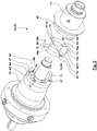
- the anti-rotation device 62 is designed as a driver coupling 63, which here has three coupling parts 64, 65, 66.
- the coupling parts 64, 66, between which the coupling part 65 is arranged and with which the coupling part 65 interacts in a manner still to be explained, can be designed as separate components or be designed integrally with the components already described.
- the coupling part 64 is held rigidly on the bearing sleeve 51, which takes place via fastening screws 67 for the exemplary embodiment shown. However, it is also entirely possible for the coupling part 64 to be formed integrally from the bearing sleeve 51.
- the coupling part 64 has an annular body 68 from which, in the direction of the drive axis 8, two drivers 69, 70 arranged in the circumferential direction on opposite sides protrude.
- the drivers 69, 70 are designed, for example, in the shape of a cuboid or a hollow cylinder segment.
- the coupling part 65 is designed as a circular disk 71 and in the area of the lateral surface has slots 72, 73, which are oriented radially inward and formed by grooves.
- the lateral boundaries of the slots 72 form drivers 84a, 84b and 75a, 75b.
- the slots 72, 73 are arranged on opposite sides in the circumferential direction.
- the drivers 69, 70 can find a precisely fitting receptacle or form a receptacle with a play or transition fit.
- carrier contacts are formed via which an anti-rotation torque can be transmitted around the drive axis 8 or eccentric axis 18, during this contact, possibly with a sliding movement between the drivers, both a movement in the radial direction to the drive axis 8 or the eccentric axis 18, in the axial direction and also an inclination of the coupling part 65 with respect to the coupling part 64.
- the circular disk 71 carries pivot bolts 76, 77 which are arranged coaxially to one another and which protrude radially outward from the circular disk 71, offset by 90 degrees in the circumferential direction.
- the pivot pins 76, 77 can extend through slots 78, 79 of the circular disk 71 formed by grooves, which slots can basically be formed in accordance with the slots 72, 73.
- the coupling part 66 is formed integrally from the flange 49 and has, on opposite sides in the circumferential direction, a driver 80 and a further driver hidden in the figures.
- the driver 80 and the concealed further driver are in the longitudinal section in Fig. 2 arranged at the level of the drive axis 8 or eccentric axis 18 in front of and behind the plane of the drawing.
- the driver 80 and the further driver each form with an associated pivot pin 76, 77 a pivot bearing for the bearing part 65, by means of which a relative pivoting of the coupling part 65 with respect to the coupling part 66 and thus with respect to the flange 49 about the axis through the longitudinal axes of the pivot pins 76, 77 predetermined pivot axis is enabled.
- pivot pins 76, 77 in bearing eyes 81 formed by the drivers 80 also ensures a limited radial relative displacement of the coupling part 65 along the pivot axis specified by the pivot bolts 76, 77 relative to the flange 49 Transmission of an anti-rotation torque around the drive axis 8 or the eccentric axis 18 between the coupling parts 65, 66 is made possible.
- the longitudinal axes of the pivot pins 76, 77 define a first transverse axis 87.
- the coupling part 65 can be pivoted relative to the coupling part 66 about the transverse axis 87. Furthermore, the coupling part 65 can be displaced along the transverse axis 87 relative to the coupling part 66.
- the slots 72, 73 provide a second transverse axis 88 along which the coupling part 64 can be displaced relative to the coupling part 65. Under certain circumstances, the engagement of the drivers 69, 70 of the coupling part 64 in the slots 72, 73 also ensures a relative axial degree of freedom 89.
- the eccentric piston 13 moves along the circular path 20
- this is accompanied on the one hand with a radial compensation movement of the drivers 69, 70 in the slots 72, 73 along the second transverse axis 88 and the pivot pins 76, 77 in the bearing eyes 81 of the drivers 80 along the first transverse axis 87.
- the movement of the eccentric piston 13 on the circular path 20 is therefore not hindered by the anti-rotation device 62.
- the anti-rotation lock 62 enables the transmission of the support torque or the anti-rotation torque, which does not allow a rotation of the eccentric piston 13 about the eccentric axis 18 or the drive axis 8.
- a displacement pump 1 claimed by the scope of the patent claims can only include the pump part 2 with the in the Fig. 2 and 3 Have described components, while an electric motor drive, for example, is not part of the positive displacement pump 1 and is therefore not the subject of the claim.
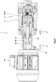
- the positive displacement pump 1 it is also entirely possible, however, for the positive displacement pump 1 to have, in addition to the pump part 2, also a drive part 82 with an electric drive, like this Fig. 4 shows.
- the positive displacement pump 1 is supported in relation to the environment via a flange 83.
- An output shaft 84 of the drive part 82 is non-rotatably connected to the pump shaft 41 via a coupling 85 compensating for angle errors but transmitting the drive torque.
- the housing 3 of the pump part 2 is via an intermediate housing 86 in which the coupling 85 is the
- the output shaft 84 connects to the pump shaft 41, connected to the housing of the drive part 82.
- the anti-rotation device 62 is referred to as a "driver coupling".
- ... coupling is not used in the sense that the structural unit identified in this way connects two shafts rotating at the same or different speeds with one another. Rather, the “driver coupling” serves to (direct or indirect) non-rotatable coupling of the eccentric piston 13 with the stator housing 5 while ensuring the required and described degrees of freedom.
Landscapes
- Engineering & Computer Science (AREA)
- Mechanical Engineering (AREA)
- General Engineering & Computer Science (AREA)
- Reciprocating Pumps (AREA)
- Polysaccharides And Polysaccharide Derivatives (AREA)
Abstract
Description
- Die Erfindung betrifft eine Verdrängerpumpe. Eine derartige Verdrängerpumpe verfügt über ein Statorgehäuse sowie einen Exzenterkolben. Der Exzenterkolben führt eine Kreisbahn relativ zu dem Statorgehäuse aus. Hierbei ist der Exzenterkolben über eine Verdrehsicherung gegenüber einer Verdrehung relativ zum Statorgehäuse gesichert. Diese Verdrehsicherung darf aber die Relativbewegung zwischen dem Exzenterkolben und dem Statorgehäuse auf der Kreisbahn nicht blockieren. Zwischen dem Statorgehäuse und dem Exzenterkolben ist mindestens eine Pumpenkammer gebildet. Das Volumen der Pumpenkammer ändert sich mit der Bewegung des Exzenterkolbens entlang der Kreisbahn, womit die Förderung des Fluides durch die Verdrängerpumpe herbeigeführt werden kann.
-
DE 697 14 935 T2 offenbart eine Verdrängerpumpe der eingangs erläuterten Art, bei der die Verdrehsicherung als zweiteiliges Wellrohr ausgebildet, welches den Exzenterkolben an dem Startergehäuse abstützt. Die Torsionssteifigkeit des Wellrohres gewährleistet die Sicherung hinsichtlich einer relativen Verdrehung zwischen dem Exzenterkolben und dem Statorgehäuse. Hingegen ist das Wellrohr biegeweich um eine Querachse und axial kompressibel ausgebildet, womit die Relativbewegung zwischen dem Exzenterkolben und dem Statorgehäuse auf der Kreisbahn ermöglicht wird. - Der vorliegenden Erfindung liegt die Aufgabe zugrunde, eine Verdrängerpumpe vorzuschlagen, die insbesondere
- hinsichtlich einer Vereinfachung der Montage und/oder
- der Gewährleistung einer Verschleißnachstellung und/oder
- der Fertigungs- und Montagetoleranzen und/oder
- der konstruktiven Ausgestaltung der Verdrehsicherung
- Die Aufgabe der Erfindung wird erfindungsgemäß mit den Merkmalen des unabhängigen Patentanspruchs gelöst. Weitere bevorzugte erfindungsgemäße Ausgestaltungen sind den abhängigen Patentansprüchen zu entnehmen.
- Die vorliegende Erfindung basiert insbesondere auf der Erkenntnis, dass bei der Verwendung eines Wellrohrs als Verdrehsicherung gemäß
DE 697 14 935 T2 ein Ziehkonflikt zu lösen ist: - Einerseits ist die Torsionssteifigkeit des Wellrohrs möglichst groß zu wählen, um eine steife Sicherung gegenüber einer relativen Verdrehung zwischen dem Exzenterkolben und dem Statorgehäuse zu vermeiden.
- Andererseits muss die Verdrehsicherung die Freiheitsgrade zur Ermöglichung der Relativbewegung zwischen dem Exzenterkolben und dem Statorgehäuse auf der Kreisbahn ermöglichen, wozu das Wellrohr möglichst weich ausgebildet sein muss.
- Zwar können die unterschiedlichen Steifigkeiten des Wellrohrs einerseits hinsichtlich einer Torsion und andererseits hinsichtlich einer Biegung, eines radialen und/oder axialen Versatzes durch die gewählte Wellenform des Wellrohrs herbeigeführt werden. Dies ist aber lediglich in eingeschränktem Ausmaß möglich.
- Erfindungsgemäß wird vorgeschlagen, dass die Verdrehsicherung als Mitnehmerkupplung ausgebildet ist. Bei der erfindungsgemäß eingesetzten Mitnehmerkupplung erfolgt die Sicherung des Exzenterkolbens hinsichtlich einer Verdrehung gegenüber dem Statorgehäuse über die Anlage von Mitnehmern von Kupplungsteilen der Mitnehmerkupplung in Umfangsrichtung. Es erfolgt somit eine diesbezügliche Sicherung durch einen Formschluss der Mitnehmer in Umfangsrichtung. Somit kann eine sehr steife Sicherung gegenüber der relativen Verdrehung erfolgen. In einigen Fällen kann auch die relative Drehstellung des Exzenterkolbens gegenüber dem Statorgehäuse sehr präzise durch die Gestaltung der Mitnehmer der Kupplungsteile vorgegeben werden. Die erforderliche Relativbewegung zwischen dem Exzenterkolben und dem Statorgehäuse auf der Kreisbahn wird hingegen durch eine Relativbewegung der Mitnehmer ermöglicht, bei der es sich beispielsweise um eine relative Gleitbewegung handeln kann. Somit erfordert diese Relativbewegung keine elastische Beaufschlagung eines elastischen Elements, wie dies bei Einsatz eines Wellrohres als Verdrehsicherung der Fall wäre.
- Für die Ausgestaltung der Mitnehmerkupplung gibt es im Rahmen der Erfindung vielfältige Möglichkeiten, sofern diese Mitnehmerkupplung einerseits die Sicherung gegenüber einer Verdrehung und andererseits die Ermöglichung der Relativbewegung auf der Kreisbahn ermöglicht. Um lediglich ein die Erfindung nicht beschränkendes Beispiel für die Mitnehmerkupplung zu nennen, kann diese als Kreuzschlitzkupplung oder Kreuzschieberkupplung oder so genannte "Oldham"-Kupplung ausgebildet sein, vgl. diesbezüglich bspw. den Eintrag zu "Oldham-Kupplung" unter Wikipedia (Datum der Einsichtnahme: 22.04.2020).
- Für einen Vorschlag der Erfindung weist die Mitnehmerkupplung drei Kupplungsteile auf. Ein erstes Kupplungsteil ist von dem Statorgehäuse ausgebildet oder (unmittelbar oder mittelbar) an diesem gehalten. Hingegen ist ein zweites Kupplungsteil von dem Exzenterkolben ausgebildet oder (unmittelbar oder mittelbar) an diesem gehalten. Schließlich ist ein drittes Kupplungsteil zwischen dem ersten Kupplungsteil und dem zweiten Kupplungsteil angeordnet. Dabei ist das dritte Kupplungsteil verschwenkbar um eine erste Querachse an dem ersten Kupplungsteil oder an dem zweiten Kupplungsteil gelagert. Hierbei gewährleistet die Lagerung auch eine axiale Verschiebung entlang der ersten Querachse. Das dritte Kupplungsteil ist darüber hinaus auch verschieblich in Richtung einer zweiten Querachse an dem anderen von dem ersten Kupplungsteil und dem zweiten Kupplungsteil gelagert. Hierbei sind die erste Querachse und die zweite Querachse orthogonal zueinander orientiert. Für diese Ausgestaltung kann die Relativbewegung zwischen dem Statorgehäuse und dem Exzenterkolben (und damit zwischen dem ersten Kupplungsteil und dem zweiten Kupplungsteil) auf einer Kreisbahn gewährleistet werden einerseits durch die Verschieblichkeit entlang der ersten Querachse und andererseits durch die Verschieblichkeit in Richtung der zweiten Querachse. Darüber hinaus gewährleistet die Verschwenkbarkeit um eine erste Querachse unter Umständen auch eine Anpassung der Neigung.
- Möglich ist im Rahmen der Erfindung auch, dass die Mitnehmerkupplung einen axialen Freiheitsgrad aufweist, was für den Einsatz der vorgenannten Kupplungsteile bedeuten kann, dass das erste Kupplungsteil axial gegenüber dem dritten Kupplungsteil verschieblich ist. Dieser axiale Freiheitsgrad kann beispielsweise zwischen dem dritten Kupplungsteil und dem anderen des ersten und zweiten Kupplungsteils gewährleistet werden, indem hier gleichzeitig die Verschieblichkeit in Richtung der zweiten Querachse und die Verschieblichkeit in Richtung des axialen Freiheitsgrades gewährleistet wird.
- Für einen besonderen Vorschlag der Erfindung ist das dritte Kupplungsteil eine Kupplungsscheibe. In diesem Fall kann die Kupplungsscheibe zwei radiale Schlitze aufweisen, die in Umfangsrichtung um 180 Grad in Umfangsrichtung versetzt zueinander angeordnet sind und somit auf gegenüberliegenden Seiten der Kupplungsscheibe angeordnet sind. Des Weiteren verfügt die Kupplungsscheibe über zwei Schwenkbolzen. Die Schwenkbolzen sind um 180 Grad in Umfangsrichtung versetzt zueinander angeordnet und somit auf gegenüberliegenden Seiten der Kupplungsscheibe angeordnet. Die Schwenkbolzen sind koaxial zueinander angeordnet. Dabei sind die Schwenkbolzen um 90 Grad in Umfangsrichtung gegenüber den vorgenannten Schlitzen versetzt angeordnet. Die Schlitze einerseits und die Schwenkbolzen andererseits sind somit entsprechend einem X oder kreuzartig an der Kupplungsscheibe vorgesehen. In diesem Fall ist der von dem Exzenterkolben ausgebildete oder an diesem (unmittelbar oder mittelbar) gehaltene Mitnehmer verdrehbar um die Längsachse des Schwenkbolzens gelagert. Der zusätzliche Verschiebe-Freiheitsgrad kann dann auf besonders einfache Weise gewährleistet werden, indem dieser Mitnehmer in Längsrichtung des Schwenkbolzens verschiebbar gegenüber dem Schwenkbolzen gelagert ist. Im einfachsten Fall kann der Mitnehmer ein Lagerauge oder eine Lagerbohrung aufweisen, durch welchen sich der Schwenkbolzen erstreckt, womit gleichzeitig der Verdreh-Freiheitsgrad und der Verschiebe-Freiheitsgrad auf einfache, aber zuverlässige Weise bereitgestellt werden können. Für diese Ausgestaltung sind in den Schlitzen zwei von dem Stator ausgebildete oder (unmittelbar oder mittelbar) an diesem gehaltene Mitnehmer verschieblich in radialer Richtung und/oder in axialer Richtung geführt. Somit bilden die Begrenzungen der Schlitze Mitnehmerflächen, an welchen entsprechende Mitnehmerflächen der von dem Statorgehäuse ausgebildeten oder hieran gehaltenen Mitnehmer zur Anlage kommen. Die Verschiebung in radialer Richtung und/oder in axialer Richtung kann dann mittels einer relativen Gleitbewegung der Mitnehmerflächen gewährleistet werden.
- Wie eingangs erläutert findet erfindungsgemäß für die Verdrehsicherung nicht (ausschließlich) ein Wellrohr oder ein torsionssteifer Faltenbalg Einsatz. Durchaus möglich ist aber, dass zusätzlich zu den genannten Maßnahmen in einer erfindungsgemäßen Verdrängerpumpe auch ein Faltenbalg Einsatz findet, über den dann zusätzlich eine Verbindung des Statorgehäuses und des Exzenterkolbens erfolgt. Möglich ist dabei auch der Einsatz eines torsionsweichen Faltenbalges, der dann ausschließlich oder vorrangig einer erforderlichen Abdichtung dienen kann, aber gleichzeitig die erforderlichen Relativbewegungen ermöglicht.
- Der Faltenbalg kann im Rahmen der Erfindung aus einem beliebigen Material hergestellt sein. Vorzugsweise ist ein Faltenbalg aus Kunststoff hergestellt. Möglich ist dabei, dass der Faltenbalg aus einem Polymermaterial, insbesondere einem PTFE, hergestellt ist.
- Vorteilhafte Weiterbildungen der Erfindung ergeben sich aus den Patentansprüchen, der Beschreibung und den Zeichnungen.
- Die in der Beschreibung genannten Vorteile von Merkmalen und von Kombinationen mehrerer Merkmale sind lediglich beispielhaft und können alternativ oder kumulativ zur Wirkung kommen, ohne dass die Vorteile zwingend von erfindungsgemäßen Ausführungsformen erzielt werden müssen.
- Hinsichtlich des Offenbarungsgehalts - nicht des Schutzbereichs - der ursprünglichen Anmeldungsunterlagen und des Patents gilt Folgendes: Weitere Merkmale sind den Zeichnungen - insbesondere den dargestellten Geometrien und den relativen Abmessungen mehrerer Bauteile zueinander sowie deren relativer Anordnung und Wirkverbindung - zu entnehmen. Die Kombination von Merkmalen unterschiedlicher Ausführungsformen der Erfindung oder von Merkmalen unterschiedlicher Patentansprüche ist ebenfalls abweichend von den gewählten Rückbeziehungen der Patentansprüche möglich und wird hiermit angeregt. Dies betrifft auch solche Merkmale, die in separaten Zeichnungen dargestellt sind oder bei deren Beschreibung genannt werden. Diese Merkmale können auch mit Merkmalen unterschiedlicher Patentansprüche kombiniert werden. Ebenso können in den Patentansprüchen aufgeführte Merkmale für weitere Ausführungsformen der Erfindung entfallen, was aber nicht für die unabhängigen Patentansprüche des erteilten Patents gilt.
- Die in den Patentansprüchen und der Beschreibung genannten Merkmale sind bezüglich ihrer Anzahl so zu verstehen, dass genau diese Anzahl oder eine größere Anzahl als die genannte Anzahl vorhanden ist, ohne dass es einer expliziten Verwendung des Adverbs "mindestens" bedarf. Wenn also beispielsweise von einem Element die Rede ist, ist dies so zu verstehen, dass genau ein Element, zwei Elemente oder mehr Elemente vorhanden sind. Diese Merkmale können durch andere Merkmale ergänzt werden oder die einzigen Merkmale sein, aus denen das jeweilige Erzeugnis besteht.
- Die in den Patentansprüchen enthaltenen Bezugszeichen stellen keine Beschränkung des Umfangs der durch die Patentansprüche geschützten Gegenstände dar. Sie dienen lediglich dem Zweck, die Patentansprüche leichter verständlich zu machen.
- Im Folgenden wird die Erfindung anhand in den Figuren dargestellter bevorzugter Ausführungsbeispiele weiter erläutert und beschrieben.
- Fig. 1
- einen Querschnitt I-I (Schnittführung s.
Fig. 2 ) eine Verdrängerpumpe. - Fig. 2
- zeigt ein Pumpenteil der Verdrängerpumpe gemäß
Fig. 1 in einem Längsschnitt II-II (Schnittführung s.Fig. 2 ). - Fig. 3
- zeigt in einer Explosionsdarstellung Bestandteile einer Verdrängerpumpe gemäß
Fig. 1 und2 mit einer Mitnehmerkupplung. - Fig. 4
- zeigt in einem Teillängsschnitt eine Verdrängerpumpe gemäß
Fig. 1 und2 mit einem Antriebsteil und einem Pumpenteil. -
Fig. 1 zeigt eine Verdrängerpumpe 1 im Bereich eines Pumpenteils 2 in einem Querschnitt I-I (bzgl. der Schnittführung vgl.Fig. 2 ). An einem Gehäuse 3, hier einem Gehäusedeckel 4, ist ein Statorgehäuse 5 gehalten. Das Statorgehäuse 5 weist ein grundsätzlich hohlzylinderförmiges Statorgehäuse-Außenteil 6 sowie ein ebenfalls hohlzylinderförmig ausgebildetes Statorgehäuse-Innenteil 7 auf. Das Statorgehäuse-Außenteil 6 und das Statorgehäuse-Innenteil 7 sind konzentrisch zu einer Antriebsachse 8 ausgebildet und angeordnet. Das Statorgehäuse-Außenteil 6 ist über einen hier ungefähr radial verlaufenden Steg 9 fest mit dem Statorgehäuse-Innenteil 7 verbunden. Zwischen dem Statorgehäuse-Außenteil 6 und dem Statorgehäuse-Innenteil 7 ist ein hohlzylindrisch ausgebildeter und koaxial zur Antriebsachse 4 orientierter Aufnahmeraum 10 ausgebildet. Benachbart zu dem Steg 9 in eine Umfangsrichtung ist in dem Statorgehäuse-Außenteil 6 ein Anschlusskanal 11 gebildet, während das Statorgehäuse-Innenteil 7 auf der in die andere Umfangsrichtung angeordneten Seite von dem Steg 9 ein Anschlusskanal 32 vorhanden ist und das das Statorgehäuse-Innenteil 7 hier einen Schlitz oder eine Öffnung 12 ausbildet. - Ein Exzenterkolben 13 verfügt über ein Exzenterkolben-Außenteil 14 und ein Exzenterkolben-Innenteil 15, die über einen Kreisringkörper 33 (vgl.
Fig. 2 ) fest miteinander verbunden sind. Das Exzenterkolben-Außenteil 14 ist hohlzylindrisch ausgebildet und verfügt über einen Schlitz oder eine Öffnung 16, durch die sich der Steg 9 des Statorgehäuses 5 erstreckt. Das Exzenterkolben-Innenteil 15 weist eine zylindrische Mantelfläche 17 auf und ist für das dargestellte Ausführungsbeispiel ebenfalls hohlzylindrisch ausgebildet. Das Exzenterkolben-Außenteil 14 und die Mantelfläche 17 des Exzenterkolben-Innenteils 15 sind konzentrisch zu einer Exzenterachse 18 angeordnet, die gegenüber der Antriebsachse 8 eine Exzentrizität 19 aufweist. - Die Exzenterachse 18 (und mit dieser der Exzenterkolben 13) bewegt sich auf einer Kreisbahn 20 um die Antriebsachse 8. Die Durchmesser der wirksamen zylindrischen Wirkflächen des Statorgehäuses 5 und des Exzenterkolbens 13 sind derart aufeinander abgestimmt, dass die Mantelfläche 17 des Exzenterkolben-Innenteils 15 einen Verbindungsspalt 21 ausbildet mit einer Innenfläche 22 des Statorgehäuse-Innenteils 7. Eine Mantelfläche 23 des Statorgehäuse-Innenteils 7 liegt auf der der Exzentrizität gegenüberliegenden Seite in einem Dichtbereich 25 an einer Innenfläche 24 des Statorgehäuse-Außenteils 6 an, während auf der in Umfangsrichtung gegenüber liegenden Seite, also in Richtung der Exzentrizität, zwischen der Mantelfläche 23 des Statorgehäuse-Innenteils 7 und der Innenfläche 24 des Exzenterkolben-Außenteils ein maximaler Spalt ausgebildet ist mit dazwischen kontinuierlich veränderter Spalthöhe. Schließlich bildet in entsprechender Weise eine Mantelfläche 30 des Exzenterkolben-Außenteils 14 in Richtung der Exzentrizität einen Dichtbereich 26 mit einer Innenfläche 27 des Statorgehäuse-Außenteils 6 aus, während diese auf der in Umfangsrichtung gegenüberliegenden Seite einen maximalen Abstand aufweisen mit dazwischen in Umfangsrichtung kontinuierlich verändertem Abstand.
- Zwischen dem Statorgehäuse-Außenteil 6 und dem Exzenterkolben-Außenteil 14 ist eine Pumpenkammer 28 gebildet, die in einem Umfangs-Endbereich abgedichtet ist durch den Dichtbereich 26. Entsprechend ist zwischen dem Exzenterkolben-Außenteil 14 und dem Statorgehäuse-Innenteil 7 eine von dem Dichtbereich 25 begrenzte Pumpenkammer 29 gebildet.
- Bewegt sich die Exzenterachse 18 auf der Kreisbahn 20 um die Antriebsachse 8, wandern die Dichtbereiche 25, 26 entsprechend in die Bewegungsrichtung 31. Während der Bewegung des Exzenterkolbens 13 auf der Kreisbahn 20 erfolgt keine Rotation des Exzenterkolbens 13 um eine parallel zur Antriebsachse 8 bzw. Exzenterachse 18 orientierte Rotationsachse. Vielmehr behalten die Querschnitte des Exzenterkolbens 13 während der Bewegung auf der Kreisbahn 20 in dem in
Fig. 1 dargestellten Querschnitt dieselbe Orientierung. - Die Förderwirkung der Verdrängerpumpe 1 wird beispielhaft für eine Bewegungsrichtung 31 des Exzenterkolbens 13 auf der Kreisbahn 20 im Uhrzeigersinn in
Fig. 1 erläutert:
In der Betriebsstellung gemäßFig. 1 , in welcher sich der Dichtbereich 26 in Bewegungsrichtung 31 hinter dem Anschlusskanal 11 befindet, kann die Pumpenkammer 28 über den Anschlusskanal 11 mit einem zu fördernden Fluid gefüllt werden. Wird der Dichtbereich 26 in Bewegungsrichtung 31 vor den Anschlusskanal 11 bewegt, schließt der Dichtbereich 26 die Verbindung zwischen dem Anschlusskanal 11 und der Pumpenkammer 28, während die Pumpenkammer 28 mit einem Anschlusskanal 32 verbunden ist. Mit weiterer Verlagerung des Dichtbereichs 26 verringert sich das Volumen der Pumpenkammer 28, da sich der Umfangsabstand des Dichtbereichs 26 von dem Anschlusskanal 32 verringert. Die Pumpenkammer 28 schiebt somit das darin angeordnete Fluid aus dem Anschlusskanal 32 aus. - Das Entsprechende gilt für die Pumpenkammer 29: Befindet sich deren Dichtbereich 25 in Bewegungsrichtung 31 hinter der Öffnung 16, kann die Pumpenkammer 29 ebenfalls aus dem Anschlusskanal 11 mit Fluid befüllt werden. In der Betriebsstellung gemäß
Fig. 1 hat sich der Dichtbereich 25 bereits nach oben verlagert, wobei die in Bewegungsrichtung 31 vor dem Dichtbereich 25 angeordnete Pumpenkammer 29 schon ihr Volumen derart verringert hat, dass auch Fluid aus der Pumpenkammer 29 aus dem Anschlusskanal 32 ausgeschoben werden kann. - Die Pumpenkammern 28, 29 sind in Umfangsrichtung auf gegenüberliegenden Seiten angeordnet, so dass diese abwechselnd Fluid ansaugen und ausschieben, womit eine von der Bewegung in Bewegungsrichtung 31 weitestgehend unabhängige Förderleistung erwirkt werden kann. Möglich ist, dass die Verdrängerpumpe 1 reversibel arbeitet, so dass eine umgekehrte Förderwirkung erzielt werden kann, wenn die Bewegungsrichtung 31 umgekehrt wird. Eine zwischen der Innenfläche 22 des Statorgehäuse-Innenteils 7 und der Mantelfläche 17 des Exzenterkolben-Innenteils 15 gebildete Kammer ist vorzugsweise nicht an der Erbringung der Förderleistung beteiligt.
- Die Gestaltung der Geometrie des Statorgehäuses 5 und des Exzenterkolbens 13 und der Pumpenkammern 28, 29 sowie deren Verbindung mit den Anschlusskanälen 11, 32 in
Fig. 1 ist lediglich beispielhaft - im Rahmen der Erfindung können auch andere aus dem Stand der Technik bekannte Ausgestaltungen hierfür verwendet werden. - In
Fig. 2 ist die weitere Ausgestaltung des Pumpenteils 2 der Verdrängerpumpe 1 in einem Längsschnitt (bzgl. der Schnittführung vgl. II-II inFig. 1 ) dargestellt. Zu erkennen ist hier, dass das Statorgehäuse 5 einen Halblängsschnitt entsprechend einem liegenden U ausbildet, wobei die Seitenschenkel des liegenden U das Statorgehäuse-Außenteil 6 und das Statorgehäuse-Innenteil 7 ausbilden und der Grundschenkel U von dem Kreisringkörper 33 gebildet ist, der in eine axiale Richtung die Pumpenkammern 28, 29 begrenzt. Das Statorgehäuse 5 ist für das dargestellte Ausführungsbeispiel einstückig ausgebildet und mit dem Gehäusedeckel 4 und einem hohlzylindrischen Gehäuseteil 34 verbunden zwecks Bildung des Gehäuses 3. Möglich ist, dass durch Stifte 35 eine Montagehilfe, Führung und/oder axiale Einstellbarkeit gewährleistet ist und/oder eine Befestigung mittels Gehäuseschrauben 36 erfolgt. - Der Exzenterkolben 13 ist mehrteilig ausgebildet und verfügt über das Exzenterkolben-Außenteil 14 sowie das Exzenterkolben-Innenteil 15 sowie eine Überwurfmutter oder -kappe 37, die gemeinsam miteinander zur Bildung des Exzenterkolbens 13 als starre Baueinheit miteinander montiert sind. Das Exzenterkolben-Außenteil 14 ist im Halblängsschnitt in der Form eines liegenden T ausgebildet. Der Vertikalschenkel des liegenden T bildet einen Ringkörper 38, dessen radial außenliegender Endbereich in die andere axiale Richtung die Pumpenkammer 28 abschließt und dessen radial innenliegender Endbereich zwischen einem Absatz des Exzenterkolben-Innenteils 15 und einer Stirnseite der Überwurfkappe 37 eingespannt ist, wozu die Überwurfkappe 37 mit einem Innengewinde auf ein Außengewinde eines axialen Fortsatzes des Exzenterkolben-Innenteils 15 aufgeschraubt sein kann.
- Eine zusätzliche Verdrehsicherung zwischen dem Exzenterkolben-Außenteil 14 und dem Exzenterkolben-Innenteil 15 kann dadurch erfolgen, dass mindestens ein in einer Längsbohrung des Exzenterkolben-Innenteils 15 aufgenommener Stift 39 formschlüssig in Umfangsrichtung aufgenommen ist in einer radialen Ausnehmung 40 der Innenfläche des Ringkörpers 38.
- Der Horizontalschenkel des liegenden T bildet auf der Innenseite die Innenfläche 24 und auf der Außenseite die Mantelfläche 30 aus.
- Ein Antrieb des Exzenterkolbens 13 zur Bewegung auf der Kreisbahn 20 erfolgt über eine um die Antriebsachse 8 rotierende Pumpenwelle 41. Die Pumpenwelle 41 hält in im Folgenden noch näher spezifizierter Weise in einem Endbereich eine Exzenterwelle 43, deren Exzenterachse 18 mit der Exzentrizität 19 gegenüber der Antriebsachse 8 versetzt ist, so dass sich die Exzenterachse 18 mit der Verdrehung der Pumpenwelle 41 auf der Kreisbahn 20 bewegt. In einem aus der Pumpenwelle 41 auskragenden Endbereich bildet die Exzenterwelle 43 einen Lagerzapfen 44, auf dem ein Innenring 45 eines Wälzlagers 46 gelagert ist. An dem Außenring 47 des Wälzlagers 46 ist eine Innenfläche 48 des Exzenterkolbens 13 abgestützt. Über diese Abstützung kann die Exzenterbewegung der Exzenterwelle 43 übertragen werden an den Exzenterkolben 13, wobei das Wälzlagers 46 ermöglicht, dass die Exzenterwelle 43 rotiert, während der Exzenterkolben 13 keine Rotationsbewegung ausführt.
- Auf der dem Ringkörper 38 abgewandten Seite des Statorgehäuses 5 bildet das Exzenterkolben-Innenteil 15 einen hülsenförmigen Flansch 49 aus. An dem Flansch 49 ist außenliegend abdichtend ein Endbereich eines Faltenbalges 50 befestigt. Der andere Endbereich des Faltenbalges 50 ist ebenfalls unter Abdichtung befestigt an einer Lagerhülse 51, die sich radial innenliegend von dem Gehäuseteil 34 koaxial zur Antriebsachse 8 erstreckt und auf hier nicht dargestellte Weise mit dem Gehäuseteil 34 fest verbunden ist. Die Lagerhülse 51 dient neben der abdichtenden Verbindung mit dem Faltenbalg 50 dazu, radial innenliegend Wälzlager 52, 53 und Dichtelemente 54 abzustützen. Die Wälzlager 52, 53 dienen der Lagerung der Pumpenwelle 41, während die Dichtelemente 54 der Abdichtung eines Innenraums des Gehäuses 3, in dem die Wälzlager 52, 53 angeordnet und geschmiert sind, dienen.
- Der Anschlusskanal 32 ist über den Zwischenraum zwischen dem Gehäuseteil 34 und dem Faltenbalg 50 verbunden mit einem fluidischen Anschluss 55, bei dem es sich je nach Bewegungsrichtung 31 und damit Drehrichtung der Pumpenwelle 41 um eine Saugseite oder eine Druckseite der Verdrängerpumpe 1 handeln kann. Auf entsprechende Weise (hier nicht dargestellt) ist der Anschlusskanal 11 mit einem fluidischen Anschluss 56 verbunden, der dann die Druckseite oder die Saugseite der Verdrängerpumpe 1 bilden kann.
- Eine axiale Abdichtung der Pumpenkammern 28, 29 erfolgt durch Anpressung der axialen Stirnseiten des Statorgehäuses 5 an zugeordnete Stirnseiten des Exzenterkolbens 13. Zu diesem Zweck stützt sich eine vorgespannte Druckfeder 47 mit einem Federfußpunkt an einem an der Innenfläche 48 des Flansches 49 abgestützten Sicherungsring 58 ab. Der andere Federfußpunkt der Druckfeder 57 ist an dem Außenring 47 des Wälzlagers abgestützt. Die Druckkraft der vorgespannten Druckfeder 57 beaufschlagt in
Fig. 2 den Exzenterkolben 13 nach links in Richtung des fest an dem Gehäuse 3 gehaltenen Statorgehäuses 5, womit die erforderliche axiale Abdichtung der Pumpenkammern 28, 29 gewährleistet ist. Kommt es infolge des Betriebs der Verdrängerpumpe 1 zu einem Verschleiß der aneinander angepressten axialen Stirnseiten, kann der Exzenterkolben 13 (verursacht durch die Druckkraft der Druckfeder 57) eine die weitere Abdichtung gewährleistende Nachstellbewegung mit einem Verschleißausgleich ausführen. - Als eine nicht zwingende Besonderheit ist die Exzenterwelle 43 nicht starr mit der Exzentrizität 19 an der Pumpenwelle 41 gehalten. Vielmehr ist die Pumpenwelle 41 über ein Schwenklager 59 verschwenkbar um eine vertikal zur Exzenterachse 18 und/oder zur Antriebsachse 8 angeordnete Schwenkachse 60 mit der Exzenterwelle 43 verbunden, wobei sich die Exzenterwelle 43 von dem Schwenklager 59 durch eine Längsausnehmung 42 aus der Pumpenwelle 41 heraus erstreckt, so dass der von einem Endbereich der Exzenterwelle 43 gebildete Lagerzapfen 44 außerhalb der Pumpenwelle 41 angeordnet ist. Für das dargestellte Ausführungsbeispiel ist das Schwenklager 59 mit einem im innenliegenden Endbereich der Exzenterwelle 43 angeordneten Lagerauge und einem das Lagerauge durchsetzenden Lagerbolzen, der im Grund der Längsausnehmung 42 angeordnet ist und die Pumpenwelle 41 in Richtung der Schwenkachse 60 durchsetzt und an der Pumpenwelle 41 gehalten ist, gebildet. Mindestens eine Dicht- und/oder Nachstellfeder 61a, 61b ist beabstandet von der Schwenkachse 60 zwischen der Innenfläche der Längsausnehmung 42 der Pumpenwelle 41 und der Exzenterwelle 43 angeordnet. Die Dicht- und/oder Nachstellfeder 61a, 61b erzeugt ein Beaufschlagungsmoment auf die Exzenterwelle 43 um die Schwenkachse 60, welches in Richtung einer Vergrößerung der Exzentrizität 19 gerichtet ist. Über die Dicht- und/oder Nachstellfeder 61a, 61b wird auf diese Weise die Exzenterwelle 43 und über das Wälzlager 46 auch der Exzenterkolben 13 so in Richtung der Exzentrizität beaufschlagt, dass in den Dichtbereichen 25, 26 eine die Dichtwirkung gewährleistende Anpresskraft erzeugt wird. Gleichzeitig kann über die Dicht- und/oder Nachstellfedern 61a, 61b bei einem Verschleiß infolge des Kontakts in den Dichtbereichen 25, 26 auch eine Vergrößerung der Exzentrizität 19 erfolgen mit einer damit einhergehenden Nachstellbewegung, mit der dann trotz eines Verschleißes weiterhin die gewünschte Dichtwirkung im Dichtbereich 25, 26 gewährleistet werden kann. Infolge der Verschwenkung um die Schwenkachse 60 ist unter Umständen die Exzenterachse 18 unter einem sehr kleinen Winkel geneigt gegenüber der Antriebsachse 8. Ein derartiger kleiner Winkel kann ausgeglichen werden durch das Wälzlager 46, welches zu diesem Zweck als Pendelkugellager ausgebildet ist.
- Für die auf Grundlage von
Fig. 1 beschriebene Pumpfunktion der Verdrängerpumpe 1 muss gewährleistet werden, dass sich bei einer Rotation der Pumpenwelle 41 und der Exzenterwelle 43 sowie des Innenrings 45 des Wälzlagers 46 (und unter Umständen auch trotz etwaiger in den Pumpenkammern 28, 29 auf den Exzenterkolben 13 ausgeübten Kräften) der Exzenterkolben 13 nicht mitdreht. Zu diesem Zweck ist in der Verdrängerpumpe 1 eine Verdrehsicherung 62 vorhanden, welche insbesondere auf Grundlage vonFig. 3 erläutert wird. - Die Verdrehsicherung 62 ist als Mitnehmerkupplung 63 ausgebildet, die hier drei Kupplungsteile 64, 65, 66 aufweist. Hierbei können die Kupplungsteile 64, 66, zwischen denen das Kupplungsteil 65 angeordnet ist und mit denen das Kupplungsteil 65 in noch zu erläuternder Weise in Wechselwirkung tritt, als separate Bauelemente ausgebildet sein oder integral mit den bereits beschriebenen Bauelementen ausgebildet sein.
- Das Kupplungsteil 64 ist starr an der Lagerhülse 51 gehalten, was für das dargestellte Ausführungsbeispiel über Befestigungsschrauben 67 erfolgt. Durchaus möglich ist aber auch, dass das Kupplungsteil 64 integral von der Lagerhülse 51 ausgebildet ist. Das Kupplungsteil 64 verfügt über einen Ringkörper 68, von dem in Richtung der Antriebsachse 8 zwei in Umfangsrichtung auf gegenüberliegenden Seiten angeordnete Mitnehmer 69, 70 hervorstehen.
- Die Mitnehmer 69, 70 sind beispielsweise quaderförmig oder hohlzylindersegmentförmig ausgebildet.
- Das Kupplungsteil 65 ist als Kreisscheibe 71 ausgebildet und verfügt im Bereich der Mantelfläche über radial nach innen orientierte, von Nuten ausgebildete Schlitze 72, 73. Die seitlichen Begrenzungen der Schlitze 72 bilden Mitnehmer 84a, 84b bzw. 75a, 75b aus. Die Schlitze 72, 73 sind in Umfangsrichtung auf gegenüberliegenden Seiten angeordnet. In den Schlitzen 72, 73 des Kupplungsteils 65 können die Mitnehmer 69, 70 passgenaue Aufnahme finden oder eine Aufnahme mit einer Spiel- oder Übergangspassung bilden. Zwischen den Mitnehmern 69, 70 des Kupplungsteils 64 und den die Schlitze 72, 73 begrenzenden Mitnehmern 74, 75 des Kupplungsteils 65 werden Mitnehmerkontakte ausgebildet, über die ein Verdrehsicherungsmoment um die Antriebsachse 8 oder Exzenterachse 18 übertragen werden kann, während dieser Kontakt, unter Umständen mit einer Gleitbewegung zwischen den Mitnehmern, sowohl eine Bewegung in radialer Richtung zu der Antriebsachse 8 oder der Exzenterachse 18, in axialer Richtung und auch eine Neigung des Kupplungsteils 65 gegenüber dem Kupplungsteil 64 ermöglichen kann.
- Um 90 Grad in Umfangsrichtung versetzt zu den Schlitzen 72, 73 trägt die Kreisscheibe 71 koaxial zueinander angeordnete Schwenkbolzen 76, 77, die radial nach außen von der Kreisscheibe 71 auskragen. Hierbei können sich die Schwenkbolzen 76, 77 durch von Nuten ausgebildete Schlitze 78, 79 der Kreisscheibe 71 erstrecken, welche grundsätzlich entsprechend den Schlitzen 72, 73 ausgebildet sein können.
- Das Kupplungsteil 66 ist für das dargestellte Ausführungsbeispiel integral von dem Flansch 49 ausgebildet und weist auf in Umfangsrichtung gegenüberliegenden Seiten einen Mitnehmer 80 und einen in den Figuren verdeckten weiteren Mitnehmer auf. Der Mitnehmer 80 und der verdeckte weitere Mitnehmer sind in dem Längsschnitt in
Fig. 2 in Höhe der Antriebsachse 8 oder Exzenterachse 18 vor und hinter der Zeichenebene angeordnet. Der Mitnehmer 80 und der weitere Mitnehmer bilden jeweils mit einem zugeordneten Schwenkbolzen 76, 77 ein Schwenklager für das Lagerteil 65, mittels dessen eine relative Verschwenkung des Kupplungsteils 65 gegenüber dem Kupplungsteil 66 und damit gegenüber dem Flansch 49 um die durch die Längsachsen der Schwenkbolzen 76, 77 vorgegebene Schwenkachse ermöglicht ist. Darüber hinaus gewährleistet die Aufnahme der Schwenkbolzen 76, 77 in von den Mitnehmern 80 ausgebildeten Lageraugen 81 auch eine begrenzte radiale relative Verschiebung des Kupplungsteils 65 entlang der durch die Schwenkbolzen 76, 77 vorgegebenen Schwenkachse relativ zu dem Flansch 49. Hingegen bilden die Schwenkbolzen 76, 77 auch Mitnehmer 90, 91 des Kupplungsteils 65, die infolge der Aufnahme in den Lageraugen 81 der Mitnehmer 80 des Kupplungsteils 66 eine Übertragung eines Verdrehsicherungsmoments um die Antriebsachse 8 oder die Exzenterachse 18 zwischen den Kupplungsteilen 65, 66 ermöglicht. - Die Längsachsen der Schwenkbolzen 76, 77 geben eine erste Querachse 87 vor. Um die Querachse 87 ist das Kupplungsteil 65 relativ zu dem Kupplungsteil 66 verschwenkbar. Des Weiteren ist das Kupplungsteil 65 entlang der Querachse 87 relativ zu dem Kupplungsteil 66 verschiebbar. Hingegen geben die Schlitze 72, 73 eine zweite Querachse 88 vor, entlang welcher das Kupplungsteil 64 relativ zu dem Kupplungsteil 65 verschieblich ist. Unter Umständen gewährleistet der Eingriff der Mitnehmer 69, 70 des Kupplungsteils 64 in die Schlitze 72, 73 auch einen relativen axialen Freiheitsgrad 89.
- Führt wie erläutert der Exzenterkolben 13 eine Bewegung entlang der Kreisbahn 20 aus, geht dies einher einerseits mit einer radialen Ausgleichbewegung der Mitnehmer 69, 70 in den Schlitzen 72, 73 entlang der zweiten Querachse 88 sowie der Schwenkbolzen 76, 77 in den Lageraugen 81 der Mitnehmer 80 entlang der ersten Querachse 87. Die Bewegung des Exzenterkolbens 13 auf der Kreisbahn 20 wird somit durch die Verdrehsicherung 62 nicht behindert. Gleichzeitig ermöglicht die Verdrehsicherung 62 aber die Übertragung des Abstützmomentes oder Verdrehsicherungsmoments, welche eine Rotation des Exzenterkolbens 13 um die Exzenterachse 18 bzw. die Antriebsachse 8 nicht zulässt.
- Eine von dem Schutzbereich der Patentansprüche beanspruchte Verdrängerpumpe 1 kann ausschließlich den Pumpenteil 2 mit den in den
Fig. 2 und3 beschriebenen Bauelementen aufweisen, während ein beispielsweise elektromotorischer Antrieb nicht Bestandteil der Verdrängerpumpe 1 ist und somit nicht Gegenstand des Patentanspruchs ist. - Durchaus möglich ist aber auch, dass die Verdrängerpumpe 1 neben dem Pumpenteil 2 auch ein Antriebsteil 82 mit einem elektrischen Antrieb aufweist, wie dies
Fig. 4 zeigt. Die Verdrängerpumpe 1 ist dabei über einen Flansch 83 gegenüber der Umgebung abgestützt. Eine Abtriebswelle 84 des Antriebsteils 82 ist über eine Winkelfehler ausgleichende, aber das Antriebsmoment übertragende Kupplung 85 drehfest verbunden mit der Pumpenwelle 41. Das Gehäuse 3 des Pumpenteils 2 ist über ein Zwischengehäuse 86, in dem die Kupplung 85 die Abtriebswelle 84 mit der Pumpenwelle 41 verbindet, mit dem Gehäuse des Antriebsteils 82 verbunden. - In der vorliegenden Beschreibung und in den Patentansprüchen ist die Verdrehsicherung 62 als "Mitnehmerkupplung" bezeichnet. Hierbei erfolgt die Verwendung der Bezeichnung "... kupplung" nicht in dem Sinne, dass die derart bezeichnete Baueinheit zwei mit gleichen oder unterschiedlichen Drehzahlen rotierende Wellen miteinander verbindet. Vielmehr dient die "Mitnehmerkupplung" der (unmittelbaren oder mittelbaren) drehfesten Kupplung des Exzenterkolbens 13 mit dem Statorgehäuse 5 unter Gewährleistung der erforderlichen und beschriebenen Freiheitsgrade.
-
- 1
- Verdrängerpumpe
- 2
- Pumpenteil
- 3
- Gehäuse
- 4
- Gehäusedeckel
- 5
- Statorgehäuse
- 6
- Statorgehäuse-Außenteil
- 7
- Statorgehäuse-Innenteil
- 8
- Antriebsachse
- 9
- Steg
- 10
- Aufnahmeraum
- 11
- Anschlusskanal
- 12
- Öffnung Statorgehäuse-Innenteil
- 13
- Exzenterkolben
- 14
- Exzenterkolben-Außenteil
- 15
- Exzenterkolben-Innenteil
- 16
- Öffnung Exzenterkolben-Außenteil
- 17
- Mantelfläche Exzenterkolben-Innenteil
- 18
- Exzenterachse
- 19
- Exzentrizität
- 20
- Kreisbahn
- 21
- Verbindungsspalt
- 22
- Innenfläche Statorgehäuse-Innenteil
- 23
- Mantelfläche Statorgehäuse-Innenteil
- 24
- Innenfläche Exzenterkolben-Außenteil
- 25
- Dichtbereich Exzenterkolben-Außenteil/Statorgehäuse-Innenteil
- 26
- Dichtbereich Exzenterkolben-Außenteil/Statorgehäuse-Außenteil
- 27
- Innenfläche Statorgehäuse-Außenteil
- 28
- Pumpenkammer
- 29
- Pumpenkammer
- 30
- Mantelfläche Exzenterkolben-Außenteil
- 31
- Bewegungsrichtung
- 32
- Anschlusskanal
- 33
- Kreisringkörper
- 34
- Gehäuseteil
- 35
- Stift
- 36
- Gehäuseschraube
- 37
- Überwurfkappe
- 38
- Ringkörper
- 39
- Stift
- 40
- Ausnehmung
- 41
- Pumpenwelle
- 42
- Längsausnehmung
- 43
- Exzenterwelle
- 44
- Lagerzapfen
- 45
- Innenring
- 46
- Wälzlager
- 47
- Außenring
- 48
- Innenfläche
- 49
- Flansch
- 50
- Faltenbalg
- 51
- Lagerhülse
- 52
- Wälzlager
- 53
- Wälzlager
- 54
- Dichtelement
- 55
- Anschluss
- 56
- Anschluss
- 57
- Druckfeder
- 58
- Sicherungsring
- 59
- Schwenklager
- 60
- Schwenkachse
- 61
- Dicht- und/oder Nachstellfeder
- 62
- Verdrehsicherung
- 63
- Mitnehmerkupplung
- 64
- Kupplungsteil
- 65
- Kupplungsteil
- 66
- Kupplungsteil
- 67
- Befestigungsschraube
- 68
- Ringkörper
- 69
- Mitnehmer
- 70
- Mitnehmer
- 71
- Kreisscheibe
- 72
- Schlitz
- 73
- Schlitz
- 74
- Mitnehmer
- 75
- Mitnehmer
- 76
- Schwenkbolzen
- 77
- Schwenkbolzen
- 78
- Schlitz
- 79
- Schlitz
- 80
- Mitnehmer
- 81
- Lagerauge
- 82
- Antriebsteil
- 83
- Flansch
- 84
- Abtriebswelle
- 85
- Kupplung
- 86
- Zwischengehäuse
- 87
- erste Querachse
- 88
- zweite Querachse
- 89
- axialer Freiheitsgrad
- 90
- Mitnehmer
- 91
- Mitnehmer
Claims (6)
- Verdrängerpumpe (1)a) mit einem Statorgehäuse (5) undb) mit einem Exzenterkolben (13),
wobeic) der Exzenterkolben (13) auf einer Kreisbahn (20) relativ zum Statorgehäuse (5) bewegt wird,d) eine Verdrehsicherung (62) vorhanden ist, welcheda) den Exzenterkolben (13) an einer Verdrehung gegenüber dem Statorgehäuse (5) hindert unddb) eine Relativbewegung zwischen dem Exzenterkolben (13) und dem Statorgehäuse (5) auf der Kreisbahn (20) ermöglicht, unde) zwischen dem Statorgehäuse (5) und dem Exzenterkolben (13) mindestens eine Pumpenkammer (28, 29) gebildet ist, deren Volumen sich mit der Bewegung des Exzenterkolbens (13) entlang der Kreisbahn (20) verändert,
dadurch gekennzeichnet, dassf) die Verdrehsicherung (62) als Mitnehmerkupplung (63) ausgebildet ist, bei derfa) die Hinderung des Exzenterkolbens (13) an einer Verdrehung gegenüber dem Statorgehäuse (5) über die Anlage von Mitnehmern (69, 70; 74, 75; 80; 90, 91) von Kupplungsteilen (64, 65, 66) der Mitnehmerkupplung (63) in Umfangsrichtung erfolgt undfb) die Relativbewegung zwischen dem Exzenterkolben (13) und dem Statorgehäuse (5) auf der Kreisbahn (20) durch eine Relativbewegung der Mitnehmer (69, 70; 74, 75; 80; 90, 91) ermöglicht wird. - Verdrängerpumpe (1) nach Anspruch 1, dadurch gekennzeichnet, dass die Mitnehmerkupplung (63) drei Kupplungsteile (64, 65, 66) aufweist, wobeia) ein erstes Kupplungsteil (64) von dem Statorgehäuse (5) ausgebildet ist oder an diesem gehalten ist,b) ein zweites Kupplungsteil (66) von dem Exzenterkolben (13) ausgebildet ist oder an diesem gehalten ist undc) ein drittes Kupplungsteil (65) zwischen dem ersten Kupplungsteil (64) und dem zweiten Kupplungsteil (66) angeordnet ist,
wobeid) das dritte Kupplungsteil (65) verschwenkbar um eine erste Querachse (87) sowie axial verschieblich entlang der ersten Querachse an einem der anderen Kupplungsteile (66) gelagert ist,e) das dritte Kupplungsteil (65) verschieblich in Richtung einer zweiten Querachse an dem anderen der anderen Kupplungsteile (64) gelagert ist undf) die erste Querachse und die zweite Querachse orthogonal zueinander orientiert sind. - Verdrängerpumpe (1) nach Anspruch 1 oder 2, dadurch gekennzeichnet, dass die Mitnehmerkupplung (63) einen axialen Freiheitsgrad (89) aufweist.
- Verdrängerpumpe (1) nach Anspruch 2 oder nach Anspruch 3 in Rückbeziehung auf Anspruch 2, dadurch gekennzeichnet, dassa) das dritte Kupplungsteil (65) eine Kupplungsscheibe (71) ist,b) die Kupplungsscheibe (71) zwei radiale Schlitze (72, 73) aufweist, die um 180° in Umfangsrichtung versetzt zueinander angeordnet sind,c) die Kupplungsscheibe (71) zwei Schwenkbolzen (76, 77) aufweist, die um 180° in Umfangsrichtung versetzt zueinander und koaxial zueinander angeordnet sind und um 90° in Umfangsrichtung gegenüber den Schlitzen (72, 73) versetzt angeordnet sind,d) wobei von dem Exzenterkolben (13) ausgebildete oder an diesem gehaltene Mitnehmer (80) verdrehbar um die Längsachse der Schwenkbolzen (76, 77) und in Längsrichtung der Schwenkbolzen (76, 77) verschiebbar gegenüber den Schwenkbolzen (76, 77) gelagert sind, unde) in den Schlitzen (72, 73) zwei von dem Statorgehäuse (5) ausgebildete oder an diesem gehaltene Mitnehmer (69, 70) verschieblich in radialer Richtung und/oder in axialer Richtung geführt sind.
- Verdrängerpumpe (1) nach einem der vorhergehenden Ansprüche, dadurch gekennzeichnet, dass das Statorgehäuse (5) und der Exzenterkolben (13) über einen Faltenbalg (50) miteinander verbunden sind.
- Verdrängerpumpe (1) nach Anspruch 5, dadurch gekennzeichnet, dass der Faltenbalg (650) aus Kunststoff, insbesondere einem Polymermaterial, beispielsweise PTFE, hergestellt ist.
Priority Applications (3)
| Application Number | Priority Date | Filing Date | Title |
|---|---|---|---|
| EP20171964.8A EP3904686B1 (de) | 2020-04-29 | 2020-04-29 | Verdrängerpumpe |
| ES20171964T ES2943501T3 (es) | 2020-04-29 | 2020-04-29 | Bomba de desplazamiento positivo |
| PL20171964.8T PL3904686T3 (pl) | 2020-04-29 | 2020-04-29 | Pompa wyporowa |
Applications Claiming Priority (1)
| Application Number | Priority Date | Filing Date | Title |
|---|---|---|---|
| EP20171964.8A EP3904686B1 (de) | 2020-04-29 | 2020-04-29 | Verdrängerpumpe |
Publications (2)
| Publication Number | Publication Date |
|---|---|
| EP3904686A1 true EP3904686A1 (de) | 2021-11-03 |
| EP3904686B1 EP3904686B1 (de) | 2023-02-01 |
Family
ID=70476101
Family Applications (1)
| Application Number | Title | Priority Date | Filing Date |
|---|---|---|---|
| EP20171964.8A Active EP3904686B1 (de) | 2020-04-29 | 2020-04-29 | Verdrängerpumpe |
Country Status (3)
| Country | Link |
|---|---|
| EP (1) | EP3904686B1 (de) |
| ES (1) | ES2943501T3 (de) |
| PL (1) | PL3904686T3 (de) |
Citations (4)
| Publication number | Priority date | Publication date | Assignee | Title |
|---|---|---|---|---|
| GB1446214A (en) * | 1972-11-01 | 1976-08-18 | Inventa Ag | Fluid operated drive arrangement |
| EP0360754A2 (de) * | 1988-09-20 | 1990-03-28 | Gutag Innovations Ag | Kreuzscheibenkupplung |
| DE69714935T2 (de) | 1996-03-22 | 2003-05-28 | Blackmer, Auxerre | Abgedichtete exzentergetriebene welle für eine verdrängerpumpe |
| JP2003336657A (ja) * | 2002-05-17 | 2003-11-28 | Sanden Corp | 軸継手およびスクロール圧縮機 |
-
2020
- 2020-04-29 ES ES20171964T patent/ES2943501T3/es active Active
- 2020-04-29 PL PL20171964.8T patent/PL3904686T3/pl unknown
- 2020-04-29 EP EP20171964.8A patent/EP3904686B1/de active Active
Patent Citations (4)
| Publication number | Priority date | Publication date | Assignee | Title |
|---|---|---|---|---|
| GB1446214A (en) * | 1972-11-01 | 1976-08-18 | Inventa Ag | Fluid operated drive arrangement |
| EP0360754A2 (de) * | 1988-09-20 | 1990-03-28 | Gutag Innovations Ag | Kreuzscheibenkupplung |
| DE69714935T2 (de) | 1996-03-22 | 2003-05-28 | Blackmer, Auxerre | Abgedichtete exzentergetriebene welle für eine verdrängerpumpe |
| JP2003336657A (ja) * | 2002-05-17 | 2003-11-28 | Sanden Corp | 軸継手およびスクロール圧縮機 |
Also Published As
| Publication number | Publication date |
|---|---|
| ES2943501T3 (es) | 2023-06-13 |
| PL3904686T3 (pl) | 2023-08-07 |
| EP3904686B1 (de) | 2023-02-01 |
Similar Documents
| Publication | Publication Date | Title |
|---|---|---|
| DE102007061322B4 (de) | Exzentergetriebe und Verfahren zum Übertragen einer Drehkraft durch das Exzentergetriebe | |
| EP2836416A1 (de) | Loslager für ein lenkgetriebe | |
| DE4031626C2 (de) | Gelenkverbinderelement | |
| EP2060824A1 (de) | Torsionsschwingungsdämpferanordnung | |
| DE102015209600A1 (de) | Kugelgewindetrieb | |
| EP3544878A1 (de) | Lenkgetriebe und lenksystem | |
| DE102010016472B3 (de) | Wälzmühle | |
| WO2007137781A1 (de) | Zahnradpumpe, insbesondere für eine servolenkung | |
| WO2013149901A1 (de) | Antriebsvorrichtung eines bremskraftverstärkers mit einer antreibbaren welle | |
| DE102005041579B4 (de) | Innenzahnradpumpe mit Füllstück | |
| DE10207118B4 (de) | Lagermechanismus und Pumpe | |
| DE3000477C2 (de) | ||
| EP3904686B1 (de) | Verdrängerpumpe | |
| EP2329161B1 (de) | Kreuzgelenkanordnung für eine gelenkwelle | |
| DE10315477A1 (de) | Axialkolbenverdichter, insbesondere CO2-Verdichter für Kraftfahrzeug-Klimaanlagen | |
| DE102008017535B3 (de) | Radialkolbenpumpe | |
| DE19620654B4 (de) | Verstellbare Axialkolbenmaschine in Schrägscheibenbauweise | |
| WO2001011276A1 (de) | Co2-kompressor | |
| EP3106698A1 (de) | Mechanisches getriebe mit integrierter lastmomentsperre | |
| DE3419307A1 (de) | Anordnung zur loesbaren reibschlussverbindung zwischen einer als hohlwelle ausgebildeten getriebeeingangswelle und einer in diese einschiebbaren antriebswelle | |
| DE2027993A1 (de) | Gelenk für eine Exzenterschneckenpumpe | |
| DE60110314T2 (de) | Axialkolbenpumpe | |
| DE10082684B4 (de) | Einrichtung zur Förderung eines gasförmigen oder flüssigen Mediums | |
| DE69602387T2 (de) | Wellenkupplungsvorrichtung | |
| DE19962035B4 (de) | Schwenkmotor |
Legal Events
| Date | Code | Title | Description |
|---|---|---|---|
| PUAI | Public reference made under article 153(3) epc to a published international application that has entered the european phase |
Free format text: ORIGINAL CODE: 0009012 |
|
| STAA | Information on the status of an ep patent application or granted ep patent |
Free format text: STATUS: REQUEST FOR EXAMINATION WAS MADE |
|
| 17P | Request for examination filed |
Effective date: 20201217 |
|
| AK | Designated contracting states |
Kind code of ref document: A1 Designated state(s): AL AT BE BG CH CY CZ DE DK EE ES FI FR GB GR HR HU IE IS IT LI LT LU LV MC MK MT NL NO PL PT RO RS SE SI SK SM TR |
|
| B565 | Issuance of search results under rule 164(2) epc |
Effective date: 20200928 |
|
| GRAP | Despatch of communication of intention to grant a patent |
Free format text: ORIGINAL CODE: EPIDOSNIGR1 |
|
| STAA | Information on the status of an ep patent application or granted ep patent |
Free format text: STATUS: GRANT OF PATENT IS INTENDED |
|
| INTG | Intention to grant announced |
Effective date: 20220907 |
|
| GRAS | Grant fee paid |
Free format text: ORIGINAL CODE: EPIDOSNIGR3 |
|
| GRAA | (expected) grant |
Free format text: ORIGINAL CODE: 0009210 |
|
| STAA | Information on the status of an ep patent application or granted ep patent |
Free format text: STATUS: THE PATENT HAS BEEN GRANTED |
|
| AK | Designated contracting states |
Kind code of ref document: B1 Designated state(s): AL AT BE BG CH CY CZ DE DK EE ES FI FR GB GR HR HU IE IS IT LI LT LU LV MC MK MT NL NO PL PT RO RS SE SI SK SM TR |
|
| REG | Reference to a national code |
Ref country code: GB Ref legal event code: FG4D Free format text: NOT ENGLISH |
|
| REG | Reference to a national code |
Ref country code: CH Ref legal event code: EP Ref country code: AT Ref legal event code: REF Ref document number: 1547006 Country of ref document: AT Kind code of ref document: T Effective date: 20230215 |
|
| REG | Reference to a national code |
Ref country code: DE Ref legal event code: R096 Ref document number: 502020002469 Country of ref document: DE |
|
| REG | Reference to a national code |
Ref country code: IE Ref legal event code: FG4D Free format text: LANGUAGE OF EP DOCUMENT: GERMAN |
|
| REG | Reference to a national code |
Ref country code: LT Ref legal event code: MG9D |
|
| REG | Reference to a national code |
Ref country code: NL Ref legal event code: MP Effective date: 20230201 |
|
| REG | Reference to a national code |
Ref country code: ES Ref legal event code: FG2A Ref document number: 2943501 Country of ref document: ES Kind code of ref document: T3 Effective date: 20230613 |
|
| P01 | Opt-out of the competence of the unified patent court (upc) registered |
Effective date: 20230529 |
|
| PG25 | Lapsed in a contracting state [announced via postgrant information from national office to epo] |
Ref country code: RS Free format text: LAPSE BECAUSE OF FAILURE TO SUBMIT A TRANSLATION OF THE DESCRIPTION OR TO PAY THE FEE WITHIN THE PRESCRIBED TIME-LIMIT Effective date: 20230201 Ref country code: PT Free format text: LAPSE BECAUSE OF FAILURE TO SUBMIT A TRANSLATION OF THE DESCRIPTION OR TO PAY THE FEE WITHIN THE PRESCRIBED TIME-LIMIT Effective date: 20230601 Ref country code: NO Free format text: LAPSE BECAUSE OF FAILURE TO SUBMIT A TRANSLATION OF THE DESCRIPTION OR TO PAY THE FEE WITHIN THE PRESCRIBED TIME-LIMIT Effective date: 20230501 Ref country code: NL Free format text: LAPSE BECAUSE OF FAILURE TO SUBMIT A TRANSLATION OF THE DESCRIPTION OR TO PAY THE FEE WITHIN THE PRESCRIBED TIME-LIMIT Effective date: 20230201 Ref country code: LV Free format text: LAPSE BECAUSE OF FAILURE TO SUBMIT A TRANSLATION OF THE DESCRIPTION OR TO PAY THE FEE WITHIN THE PRESCRIBED TIME-LIMIT Effective date: 20230201 Ref country code: LT Free format text: LAPSE BECAUSE OF FAILURE TO SUBMIT A TRANSLATION OF THE DESCRIPTION OR TO PAY THE FEE WITHIN THE PRESCRIBED TIME-LIMIT Effective date: 20230201 Ref country code: HR Free format text: LAPSE BECAUSE OF FAILURE TO SUBMIT A TRANSLATION OF THE DESCRIPTION OR TO PAY THE FEE WITHIN THE PRESCRIBED TIME-LIMIT Effective date: 20230201 |
|
| PG25 | Lapsed in a contracting state [announced via postgrant information from national office to epo] |
Ref country code: SE Free format text: LAPSE BECAUSE OF FAILURE TO SUBMIT A TRANSLATION OF THE DESCRIPTION OR TO PAY THE FEE WITHIN THE PRESCRIBED TIME-LIMIT Effective date: 20230201 Ref country code: IS Free format text: LAPSE BECAUSE OF FAILURE TO SUBMIT A TRANSLATION OF THE DESCRIPTION OR TO PAY THE FEE WITHIN THE PRESCRIBED TIME-LIMIT Effective date: 20230601 Ref country code: GR Free format text: LAPSE BECAUSE OF FAILURE TO SUBMIT A TRANSLATION OF THE DESCRIPTION OR TO PAY THE FEE WITHIN THE PRESCRIBED TIME-LIMIT Effective date: 20230502 Ref country code: FI Free format text: LAPSE BECAUSE OF FAILURE TO SUBMIT A TRANSLATION OF THE DESCRIPTION OR TO PAY THE FEE WITHIN THE PRESCRIBED TIME-LIMIT Effective date: 20230201 |
|
| PG25 | Lapsed in a contracting state [announced via postgrant information from national office to epo] |
Ref country code: SM Free format text: LAPSE BECAUSE OF FAILURE TO SUBMIT A TRANSLATION OF THE DESCRIPTION OR TO PAY THE FEE WITHIN THE PRESCRIBED TIME-LIMIT Effective date: 20230201 Ref country code: RO Free format text: LAPSE BECAUSE OF FAILURE TO SUBMIT A TRANSLATION OF THE DESCRIPTION OR TO PAY THE FEE WITHIN THE PRESCRIBED TIME-LIMIT Effective date: 20230201 Ref country code: EE Free format text: LAPSE BECAUSE OF FAILURE TO SUBMIT A TRANSLATION OF THE DESCRIPTION OR TO PAY THE FEE WITHIN THE PRESCRIBED TIME-LIMIT Effective date: 20230201 Ref country code: DK Free format text: LAPSE BECAUSE OF FAILURE TO SUBMIT A TRANSLATION OF THE DESCRIPTION OR TO PAY THE FEE WITHIN THE PRESCRIBED TIME-LIMIT Effective date: 20230201 Ref country code: CZ Free format text: LAPSE BECAUSE OF FAILURE TO SUBMIT A TRANSLATION OF THE DESCRIPTION OR TO PAY THE FEE WITHIN THE PRESCRIBED TIME-LIMIT Effective date: 20230201 |
|
| REG | Reference to a national code |
Ref country code: DE Ref legal event code: R097 Ref document number: 502020002469 Country of ref document: DE |
|
| PG25 | Lapsed in a contracting state [announced via postgrant information from national office to epo] |
Ref country code: SK Free format text: LAPSE BECAUSE OF FAILURE TO SUBMIT A TRANSLATION OF THE DESCRIPTION OR TO PAY THE FEE WITHIN THE PRESCRIBED TIME-LIMIT Effective date: 20230201 |
|
| REG | Reference to a national code |
Ref country code: CH Ref legal event code: PL |
|
| PLBE | No opposition filed within time limit |
Free format text: ORIGINAL CODE: 0009261 |
|
| STAA | Information on the status of an ep patent application or granted ep patent |
Free format text: STATUS: NO OPPOSITION FILED WITHIN TIME LIMIT |
|
| PG25 | Lapsed in a contracting state [announced via postgrant information from national office to epo] |
Ref country code: LU Free format text: LAPSE BECAUSE OF NON-PAYMENT OF DUE FEES Effective date: 20230429 |
|
| 26N | No opposition filed |
Effective date: 20231103 |
|
| REG | Reference to a national code |
Ref country code: BE Ref legal event code: MM Effective date: 20230430 |
|
| PG25 | Lapsed in a contracting state [announced via postgrant information from national office to epo] |
Ref country code: MC Free format text: LAPSE BECAUSE OF FAILURE TO SUBMIT A TRANSLATION OF THE DESCRIPTION OR TO PAY THE FEE WITHIN THE PRESCRIBED TIME-LIMIT Effective date: 20230201 |
|
| PG25 | Lapsed in a contracting state [announced via postgrant information from national office to epo] |
Ref country code: SI Free format text: LAPSE BECAUSE OF FAILURE TO SUBMIT A TRANSLATION OF THE DESCRIPTION OR TO PAY THE FEE WITHIN THE PRESCRIBED TIME-LIMIT Effective date: 20230201 Ref country code: MC Free format text: LAPSE BECAUSE OF FAILURE TO SUBMIT A TRANSLATION OF THE DESCRIPTION OR TO PAY THE FEE WITHIN THE PRESCRIBED TIME-LIMIT Effective date: 20230201 Ref country code: LI Free format text: LAPSE BECAUSE OF NON-PAYMENT OF DUE FEES Effective date: 20230430 Ref country code: CH Free format text: LAPSE BECAUSE OF NON-PAYMENT OF DUE FEES Effective date: 20230430 |
|
| REG | Reference to a national code |
Ref country code: IE Ref legal event code: MM4A |
|
| PG25 | Lapsed in a contracting state [announced via postgrant information from national office to epo] |
Ref country code: BE Free format text: LAPSE BECAUSE OF NON-PAYMENT OF DUE FEES Effective date: 20230430 |
|
| PG25 | Lapsed in a contracting state [announced via postgrant information from national office to epo] |
Ref country code: IE Free format text: LAPSE BECAUSE OF NON-PAYMENT OF DUE FEES Effective date: 20230429 |
|
| PG25 | Lapsed in a contracting state [announced via postgrant information from national office to epo] |
Ref country code: IE Free format text: LAPSE BECAUSE OF NON-PAYMENT OF DUE FEES Effective date: 20230429 |
|
| PG25 | Lapsed in a contracting state [announced via postgrant information from national office to epo] |
Ref country code: BG Free format text: LAPSE BECAUSE OF FAILURE TO SUBMIT A TRANSLATION OF THE DESCRIPTION OR TO PAY THE FEE WITHIN THE PRESCRIBED TIME-LIMIT Effective date: 20230201 |
|
| PG25 | Lapsed in a contracting state [announced via postgrant information from national office to epo] |
Ref country code: BG Free format text: LAPSE BECAUSE OF FAILURE TO SUBMIT A TRANSLATION OF THE DESCRIPTION OR TO PAY THE FEE WITHIN THE PRESCRIBED TIME-LIMIT Effective date: 20230201 |
|
| GBPC | Gb: european patent ceased through non-payment of renewal fee |
Effective date: 20240429 |
|
| PG25 | Lapsed in a contracting state [announced via postgrant information from national office to epo] |
Ref country code: GB Free format text: LAPSE BECAUSE OF NON-PAYMENT OF DUE FEES Effective date: 20240429 |
|
| PG25 | Lapsed in a contracting state [announced via postgrant information from national office to epo] |
Ref country code: GB Free format text: LAPSE BECAUSE OF NON-PAYMENT OF DUE FEES Effective date: 20240429 |
|
| PGFP | Annual fee paid to national office [announced via postgrant information from national office to epo] |
Ref country code: PL Payment date: 20250417 Year of fee payment: 6 Ref country code: DE Payment date: 20250212 Year of fee payment: 6 |
|
| PGFP | Annual fee paid to national office [announced via postgrant information from national office to epo] |
Ref country code: ES Payment date: 20250519 Year of fee payment: 6 |
|
| PGFP | Annual fee paid to national office [announced via postgrant information from national office to epo] |
Ref country code: IT Payment date: 20250430 Year of fee payment: 6 |
|
| PGFP | Annual fee paid to national office [announced via postgrant information from national office to epo] |
Ref country code: FR Payment date: 20250425 Year of fee payment: 6 |
|
| PGFP | Annual fee paid to national office [announced via postgrant information from national office to epo] |
Ref country code: AT Payment date: 20250721 Year of fee payment: 5 |
|
| PG25 | Lapsed in a contracting state [announced via postgrant information from national office to epo] |
Ref country code: CY Free format text: LAPSE BECAUSE OF FAILURE TO SUBMIT A TRANSLATION OF THE DESCRIPTION OR TO PAY THE FEE WITHIN THE PRESCRIBED TIME-LIMIT; INVALID AB INITIO Effective date: 20200429 |
|
| PG25 | Lapsed in a contracting state [announced via postgrant information from national office to epo] |
Ref country code: HU Free format text: LAPSE BECAUSE OF FAILURE TO SUBMIT A TRANSLATION OF THE DESCRIPTION OR TO PAY THE FEE WITHIN THE PRESCRIBED TIME-LIMIT; INVALID AB INITIO Effective date: 20200429 |
|
| PG25 | Lapsed in a contracting state [announced via postgrant information from national office to epo] |
Ref country code: TR Free format text: LAPSE BECAUSE OF FAILURE TO SUBMIT A TRANSLATION OF THE DESCRIPTION OR TO PAY THE FEE WITHIN THE PRESCRIBED TIME-LIMIT Effective date: 20230201 |