EP3904687B1 - Pompe à engrenages - Google Patents
Pompe à engrenages Download PDFInfo
- Publication number
- EP3904687B1 EP3904687B1 EP20171681.8A EP20171681A EP3904687B1 EP 3904687 B1 EP3904687 B1 EP 3904687B1 EP 20171681 A EP20171681 A EP 20171681A EP 3904687 B1 EP3904687 B1 EP 3904687B1
- Authority
- EP
- European Patent Office
- Prior art keywords
- gear
- lubrification
- sealing surface
- gear pump
- driving profile
- Prior art date
- Legal status (The legal status is an assumption and is not a legal conclusion. Google has not performed a legal analysis and makes no representation as to the accuracy of the status listed.)
- Active
Links
Images

Classifications
-
- F—MECHANICAL ENGINEERING; LIGHTING; HEATING; WEAPONS; BLASTING
- F04—POSITIVE - DISPLACEMENT MACHINES FOR LIQUIDS; PUMPS FOR LIQUIDS OR ELASTIC FLUIDS
- F04C—ROTARY-PISTON, OR OSCILLATING-PISTON, POSITIVE-DISPLACEMENT MACHINES FOR LIQUIDS; ROTARY-PISTON, OR OSCILLATING-PISTON, POSITIVE-DISPLACEMENT PUMPS
- F04C2/00—Rotary-piston machines or pumps
- F04C2/08—Rotary-piston machines or pumps of intermeshing-engagement type, i.e. with engagement of co-operating members similar to that of toothed gearing
- F04C2/12—Rotary-piston machines or pumps of intermeshing-engagement type, i.e. with engagement of co-operating members similar to that of toothed gearing of other than internal-axis type
- F04C2/14—Rotary-piston machines or pumps of intermeshing-engagement type, i.e. with engagement of co-operating members similar to that of toothed gearing of other than internal-axis type with toothed rotary pistons
- F04C2/18—Rotary-piston machines or pumps of intermeshing-engagement type, i.e. with engagement of co-operating members similar to that of toothed gearing of other than internal-axis type with toothed rotary pistons with similar tooth forms
-
- F—MECHANICAL ENGINEERING; LIGHTING; HEATING; WEAPONS; BLASTING
- F04—POSITIVE - DISPLACEMENT MACHINES FOR LIQUIDS; PUMPS FOR LIQUIDS OR ELASTIC FLUIDS
- F04C—ROTARY-PISTON, OR OSCILLATING-PISTON, POSITIVE-DISPLACEMENT MACHINES FOR LIQUIDS; ROTARY-PISTON, OR OSCILLATING-PISTON, POSITIVE-DISPLACEMENT PUMPS
- F04C15/00—Component parts, details or accessories of machines, pumps or pumping installations, not provided for in groups F04C2/00 - F04C14/00
- F04C15/0057—Driving elements, brakes, couplings, transmission specially adapted for machines or pumps
- F04C15/0061—Means for transmitting movement from the prime mover to driven parts of the pump, e.g. clutches, couplings, transmissions
- F04C15/0073—Couplings between rotors and input or output shafts acting by interengaging or mating parts, i.e. positive coupling of rotor and shaft
-
- F—MECHANICAL ENGINEERING; LIGHTING; HEATING; WEAPONS; BLASTING
- F04—POSITIVE - DISPLACEMENT MACHINES FOR LIQUIDS; PUMPS FOR LIQUIDS OR ELASTIC FLUIDS
- F04C—ROTARY-PISTON, OR OSCILLATING-PISTON, POSITIVE-DISPLACEMENT MACHINES FOR LIQUIDS; ROTARY-PISTON, OR OSCILLATING-PISTON, POSITIVE-DISPLACEMENT PUMPS
- F04C15/00—Component parts, details or accessories of machines, pumps or pumping installations, not provided for in groups F04C2/00 - F04C14/00
- F04C15/0088—Lubrication
Definitions
- the current invention relates to gear pumps, in particular to spur-toothed external gear pumps that are easy to maintain and easy to clean after a pumping process.
- gear pumps have a pump housing, in which a drive gear and an idler gear are rotatably mounted.
- the housing is laterally closed off on one side with a flange and on the opposite side thereof is closed off with a cover.
- the flange comprising a drive shaft and a coupling piece, by means of which the drive shaft is operatively connected to the drive gear.
- gear pump is disclosed in CN 105298834 .
- gear pumps are disclosed in US 5 391 068 , in US 2 346 761 and in DE 1 528 959 . These known gear pumps have the disadvantage of comprising a rather high number of spare parts resulting in high maintenance costs.
- a problem to be solved is the provision of a gear pump that is easy to maintain.
- a gear pump comprises a housing with a spur-toothed drive gear and a spur-toothed idle gear that are mounted rotatably around two parallel rotation axes within the housing with bushings.
- a connecting flange is arranged on a first lateral side of the housing, in the direction of the axes.
- a cover is arranged on a second lateral side of the housing, opposite the connecting flange.
- a drive shaft is rotatably mounted in the connecting flange by at least one bearing and is sealed against the connecting flange by at least one shaft seal, wherein the drive shaft is operatively connected to the drive gear by a coupling piece coupled to the drive shaft by a complementary profile.
- the drive gear and the idle gear are identical.
- each gear comprises a first bearing pin arranged on a first lateral side of the gear and a second bearing pin arranged on a second lateral side of the gear, opposite to the first lateral side.
- the axis of rotation of the bearing pins are congruent and the length and the diameter of the bearing pins are identical.
- the first bearing pin comprises an internal driving profile.
- the first bearing pin and the second bearing pin comprise an internal driving profile.
- the coupling piece extends along a longitudinal axis and comprises a driving profile over its entire length that is complementary to the driving profile of the gears or the driving profile of the drive shaft, respectively.
- the driving profile of the gears or the drive shaft is an internal profile
- the driving profile of the coupling piece is an external profile and vice versa. Therefore, if the drive gear comprises an internal drive profile and the drive shaft comprises an external drive, the coupling piece comprises an external driving profile on its one side and an internal driving profile on its other side.
- the gear pump can be taken apart individually, upon requirement, i.e. the seals can be replaced without removing the gears, or the gears can be replaced without removing the seals. Additionally, fewer spare parts are needed as the drive gear and the idle gear are interchangeable.
- the driving profile is part of a form-fit shaft-hub connection with a shaft selected from the group comprising polygon shaft, toothed shaft, splined shaft and cycloidal shaft.
- a shaft selected from the group comprising polygon shaft, toothed shaft, splined shaft and cycloidal shaft.
- any regular or irregular profile can be used that can act as a driving profile.
- a lubrification channel extends along the axis of rotation through each gear, from the first bearing pin to the second bearing pin, i.e. through the entire length of each gear.
- the drive shaft extends along a longitudinal axis from a first end to 25 a second end. The second end of the drive shaft comprises a driving profile.
- the driving profile of the drive shaft is identical to the driving profile of the gears, i.e. they all are either internal driving profiles or external profiles with identical cross-sections.
- a lubrification channel extends along the longitudinal axis of the drive shaft, at least in the region of the second end.
- the lubrification channel has a lateral opening spaced apart from the second end of the drive shaft.
- the first end of the drive shaft comprises a connecting profile for the connection to a drive element.
- the connecting profile acting as a driving profile is part of a form-fit shaft-hub connection with a shaft selected from the group comprising polygon shaft, toothed shaft, splined shaft and cycloidal shaft.
- any regular or irregular profile can be used that can act as a driving profile.
- a lubrification channel extends along the longitudinal axis over the entire length of the coupling piece.
- a first sealing surface of the housing faces a sealing surface of the connecting flange
- a second sealing surface of the housing faces a sealing surface of the cover.
- the end faces of the first bearing pin of the drive gear and of the idle gear and the outside end faces of the corresponding bushes are flush with the first sealing surface.
- the end faces of the second bearing pin of the drive gear and of the idle gear and the outside end faces of the corresponding bushes are flush with the second sealing surface.
- the sealing surface of the connecting flange comprises a sealing groove surrounding the corresponding bushes and comprises a first sealing ring.
- the sealing surface of the cover comprises a sealing groove surrounding the corresponding bushes and comprises a second sealing ring.
- the connecting flange comprises a seal cover that is removable from a side opposite the housing.
- the at least one bearing, the at least one shaft seal and the drive shaft are securely arranged in a recess in the seal cover. This design allows for the exchange of the shaft seal of the drive shaft without the need to disassemble the gear pump otherwise.
- the sealing surface of the connecting flange comprises a lubrification groove for connecting the lubrification channel of the idle gear with a lubrification port adjacent to the drive shaft and the sealing surface of the cover comprises a lubrification groove for connecting the lubrification channel of the drive gear with the lubrification channel of the idle gear.
- the lubrification groove of the connecting flange extends from a region comprising the projection of the lubrification channel of the idle gear in the direction of the axis of rotation and the lubrification groove of the cover extends from a region comprising the projection of the lubrification channel of the drive gear in the direction of the axis of rotation to a region comprising the projection of the lubrification channel of the idle gear in the direction of the axis of rotation.
- the gear pump comprises a lubrification channel insert that extends along a longitudinal axis and comprising a driving profile over its entire length that is complementary to the driving profile of the idle gear and a lubrification channel that extends along the longitudinal axis over the entire length of the lubrification insert.
- the length of the lubrification channel insert is identical to the length of a recess in the idle gear comprising the driving profile and an adjoining undercut for the driving profile. If the lubrification channel insert is introduced in said recess, the lubrification channel of the lubrification channel insert connects the lubrification channel of the idle gear to the lubrification groove of the connecting flange.
- the housing is clamped between the connecting flange and the cover by means of clamping elements.
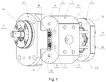
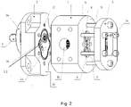
- Fig. 1 shows a perspective exploded view of a gear pump 15 according to the present invention and Fig. 2 shows an alternative view of the exploded view of Fig. 1 .
- the gear pump comprises a housing 1 with a spur-toothed drive gear 4 and a spur-toothed idle gear 5 that are mounted rotatably around two parallel rotation axes within the housing 1 comprising bushings 8.
- a connecting flange 2 is arranged on a first lateral side of the housing 1 in the direction of the axes.
- a cover 3 is arranged on a second lateral side of the housing 1, opposite the connecting flange 2.
- a drive shaft 7 is rotatably mounted in the connecting flange 2.
- the housing 1 comprises a pressure port 10 and a suction port 11.
- the housing 1 further comprises a first sealing surface 12 facing the connecting flange 2 and a second sealing surface 13 facing the cover 3. Through holes 14 extend from the first sealing surface 12 to the second sealing surface 13.
- the connecting flange 2 comprises a sealing surface 20 facing the housing 1.
- the sealing surface 20 comprises a lubrification groove 22 extending from a region of the rotation axis of the idle gear 5 to a location adjacent to the drive shaft 7.
- the connecting flange 2 further comprises thread holes 23 that are distributed around the periphery of the sealing surface 20.
- the connecting flange 2 further comprises a seal cover 24 that is removable from a side opposite the housing 1 and that is secured to the housing by means of screws.
- the drive shaft 7 is rotatably arranged in the seal cover 24.
- the cover 3 comprises a sealing surface 30 facing the housing 1.
- the sealing surface 20 of the connecting flange 2 comprises a lubrification groove 22 extending from a region of the rotation axis of the drive gear 4 to a region of the rotation axis of the idle gear 5.
- the cover 3 further comprises through holes 33 distributed around the periphery of the sealing surface 30 and extending from the sealing surface 30 through the entire thickness of the cover 3.
- screws 34 extend through the through holes 33 of the cover 3 and the through holes 14 of the housing 1 and are screwed-in in the thread holes 23 of the connecting flange 2.
- the housing 1 is clamped between the connecting flange 2 and the cover 3 by said screws 34.
- the sealing surface 20 of the connecting flange 2 comprises a closed sealing groove 21 that surrounds the corresponding region of the end faces of the bushings 8 and a corresponding lubrification groove 22 in the sealing surface 20 of the connecting flange 2.
- a first sealing ring 90 is arranged in said sealing groove 21 of the connecting flange 2.
- the sealing surface 30 of the cover 3 comprises a closed sealing groove 31 that surrounds the corresponding region of the end faces of the bushings 8 und the corresponding lubrification groove 32 in the sealing surface 30 of the cover 3.
- a second sealing ring 91 is arranged in said sealing groove 32.
- Fig. 3 shows a sectional view of the gear pump of Fig. 1 .
- the section being in a plane defined by the axis of rotation of the gears 4 and 5 and the drive shaft 7.
- Both, the drive gear 4 and the idle gear 5, are rotatably arranged with bushings 8 within a recess in the housing 1.
- the bushings 8 are arranged on both sides of each gear 4 and 5, respectively.
- the recess extends along the axis of rotation of the gears 4 and 5 through the entire housing 1 from the first sealing surface 12 to the second sealing surface 13. This design allows the introduction or the removal of the gears 4 and 5 and the bushings 8 from either side of the recess.
- There are bearing pins on both sides of the gears 4 and 5 which rest within the corresponding bushings 8.
- a coupling piece 6 is partially introduced in a complementary recess in the drive gear 4. The rest of the coupling piece 6 extends over the first sealing surface 12 and into a complementary recess in the drive shaft 7.
- the drive shaft 7 is rotatably mounted in the seal cover 24 of the connecting flange 2 with two bearings 80. The drive shaft 7 is sealed against the seal cover 24 with one shaft seal 9.
- the drive shaft 7, the bearings 80 and the shaft seal 9 are secured in a recess in the seal cover 24 by means of a retaining element, i.e.
- the seal cover 24 has a cylindrical husk body that is introduced into a corresponding recess of the flange body of the connecting flange 2.
- the seal cover 24 comprises a brim that extends laterally over the diameter of the husk body. Through holes are evenly distributed around the circumference of the brim.
- the seal cover 24 is fixed to the flange body by means of screws (see Fig. 1 ).
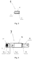
- Fig. 4 shows a partial sectional view of a gear according to the present invention, i.e. the drive gear 4 or the idle gear 5.
- the gear 4 comprises a gearing 40 located in its middle and extending in the direction of the axis of rotation A.
- a first bearing pin 41 extends along the axis of rotation A having an outside diameter that is smaller than the outside diameter of the gearing 40 and having a length that is shorter than the width of the gearing 40.
- a second bearing pin 42 is arranged on the opposite side of the gearing 40, having an outside diameter and a length that are identical to the ones of the first bearing pin.
- a recess is provided centrically in the first bearing pin 41 extending from the end face.
- the recess comprising a toothing 43 complementary to the one of the coupling piece 6 and an undercut adjoining the toothing 43.
- a lubrification channel 44 extends along the axis of rotation A from the undercut towards the end face of the second bearing pin 42.
- Fig. 5 shows a sectional view of a coupling piece 6 according to the present invention.
- the coupling piece 6 has a cylindrical body that extends along a longitudinal axis L that comprises an external toothing 60 along its entire length that is complementary to the one of the drive gear 4 and the drive shaft 7.
- a lubrification channel 61 extends along the longitudinal axis L over the entire length of the coupling piece 6.
- Fig. 6 shows a partial sectional view of a drive shaft 7 according to the present invention.
- the drive shaft 7 has a cylindrical body 70 that extends along a longitudinal axis L from a first end 71 to an opposite second end 72.
- the first end 71 having an outside diameter that is smaller than the one of an adjoining middle section, and the outside diameter of the middle section is smaller than the one of the adjoining second end 71.
- the outside diameter of the second end 71 is identical to the outside diameter of the bearing pins 41, 42 of the drive gear 4.
- a recess is provided centrically in the second end 72 extending from the end face towards the middle section.
- the recess comprising a gearing 73 complementary to the one of the coupling piece 6 and an undercut adjoining the gearing 73.
- a lubrification channel 74 extends along the longitudinal axis L from the undercut into the middle section. From there, the lubrification channel 74 extends essentially perpendicular to the longitudinal axis L towards a lateral opening 740.
- the diameter of the lubrification channel 74 of the drive shaft 7 is Identical to the one of the coupling piece 6 and the gears 4, 5.
- a connecting groove 75 in the form of a keyseat is provided at the first end 71.
Landscapes
- Engineering & Computer Science (AREA)
- Mechanical Engineering (AREA)
- General Engineering & Computer Science (AREA)
- Rotary Pumps (AREA)
Claims (14)
- Pompe à engrenages comprenant un boîtier (1) avec un pignon d'entraînement (4) à denture droite et un pignon fou (5) à denture droite qui sont montés rotatifs autour de deux axes de rotation parallèles à l'intérieur du boîtier (1) comprenant des douilles (8), une bride de raccordement (2) qui est disposée sur un premier côté latéral du boîtier (1) dans la direction des axes, un couvercle (3) qui est disposé sur un deuxième côté latéral du boîtier (1) opposé à la bride de raccordement (2), un arbre d'entraînement (7) qui est monté rotatif dans la bride de raccordement (2) par au moins un palier (80) et qui est rendu étanche par rapport à la bride de raccordement (2) par au moins un joint d'arbre (9), le pignon d'entraînement (4) et le pignon fou (5) étant identiques, caractérisé en ce que l'arbre d'entraînement (7) est relié fonctionnellement au pignon d'entraînement (4) par une pièce d'accouplement (6) couplée à l'arbre d'entraînement (7) par un profil complémentaire, chaque pignon (4 ; 5) comprenant un premier tourillon (41) disposé sur un premier côté latéral de l'engrenage (4 ; 5) et un deuxième tourillon (42) disposé sur un deuxième côté latéral de l'engrenage (4 ; 5), opposé au premier côté latéral, dans lequel les axes de rotation (A) des tourillons (41 ; 42) sont congruents et la longueur et le diamètre des tourillons (41 ; 42) sont identiques, le premier tourillon (41) présentant un profil d'entraînement interne (43) ou le premier tourillon (41) et le deuxième tourillon (42) présentant un profil d'entraînement interne (43) et la pièce d'accouplement (6) s'étendant le long d'un axe longitudinal (L) et présentant sur toute sa longueur un profil d'entraînement (60) complémentaire du profil d'entraînement (43) des roues dentées (4 ; 5) ou du profil d'entraînement (73) de l'arbre d'entraînement (7).
- Pompe à engrenages selon la revendication 1, dans laquelle le profil d'entraînement (43) fait partie d'une connexion arbre-moyeu à ajustement de forme avec un arbre choisi dans le groupe comprenant un arbre polygonal, un arbre denté, un arbre cannelé et un arbre cycloïdal.
- Pompe à engrenages selon l'une des revendications 1 ou 2, dans laquelle un canal de lubrification (44) s'étendant le long de l'axe de rotation (A) à travers chaque engrenage (4 ; 5) depuis le premier tourillon (41) jusqu'au second tourillon (42).
- Pompe à engrenages selon l'une des revendications précédentes, dans laquelle l'arbre d'entraînement (7) s'étendant le long d'un axe longitudinal (L) d'une première extrémité (71) à une seconde extrémité (72), la seconde extrémité (72) comprenant un profil d'entraînement (73).
- Pompe à engrenages selon la revendication 4, dans laquelle le profil d'entraînement (73) de l'arbre d'entraînement (7) est identique au profil d'entraînement (43) des engrenages (4 ; 5).
- Pompe à engrenages selon la revendication 4 ou 5, dans laquelle un canal de lubrification (74) s'étendant le long de l'axe longitudinal (L) de l'arbre d'entraînement (7), au moins dans la région de la deuxième extrémité (72) et présentant une ouverture de lubrification latérale (740), à distance de la deuxième extrémité (72).
- Pompe à engrenages selon la revendication 5 ou 6, dans laquelle la première extrémité (71) de l'arbre d'entraînement (7) comprend un profil de raccordement (75) pour le raccordement à un élément d'entraînement.
- Pompe à engrenages selon la revendication 1, dans laquelle il est prévu un canal de lubrification (61) s'étendant le long de l'axe longitudinal (L) sur toute la longueur de la pièce d'accouplement (6).
- Pompe à engrenages selon l'une des revendications précédentes, dans laquelle une première surface d'étanchéité (12) du carter (1) fait face à une surface d'étanchéité (20) de la bride de raccordement (2) et dans laquelle une deuxième surface d'étanchéité (13) du carter (1) fait face à une surface d'étanchéité (30) du couvercle (3) et dans laquelle les faces d'extrémité des premiers tourillons (41) et les faces d'extrémité extérieures des douilles correspondantes (8) sont en affleurement avec la première surface d'étanchéité (12) et dans lequel les faces d'extrémité des seconds tourillons (42) et les faces d'extrémité extérieures des douilles correspondantes (8) sont en affleurement avec la seconde surface d'étanchéité (13) .
- Pompe à engrenages selon la revendication 9, dans laquelle la surface d'étanchéité (20) de la bride de connexion (2) comprenant une rainure d'étanchéité (21) entourant les douilles correspondantes (8) et comprenant une première bague d'étanchéité (90), et dans laquelle la surface d'étanchéité (30) du couvercle (3) comprenant une rainure d'étanchéité (31) entourant les douilles correspondantes (8) et comprenant une seconde bague d'étanchéité (91).
- Pompe à engrenages selon l'une des revendications précédentes, dans laquelle la bride de raccordement (2) comprend un couvercle d'étanchéité (24) amovible depuis un côté opposé au boîtier (1) et dans laquelle le au moins un palier (80), le au moins un joint d'arbre (9) et l'arbre d'entraînement (7) sont disposés de manière fixe dans un évidement du couvercle d'étanchéité (24).
- Pompe à engrenages selon l'une des revendications 9 à 11, dans laquelle la surface d'étanchéité (20) de la bride de raccordement (2) comprend une rainure de lubrification (22) pour relier le canal de lubrification du pignon fou (5) à un orifice de lubrification adjacent à l'arbre d'entraînement (7), et dans laquelle la surface d'étanchéité (30) du couvercle (3) comprend une rainure de lubrification (32) pour relier le canal de lubrification du pignon d'entraînement (4) au canal de lubrification de l'arbre d'entraînement (7).
- Pompe à engrenages selon l'une des revendications 8 à 12, comprenant un insert de canal de lubrification s'étendant le long d'un axe longitudinal et comprenant un profil d'entraînement sur toute sa longueur qui est complémentaire au profil d'entraînement du pignon fou (5) et comprenant un canal de lubrification s'étendant le long de l'axe longitudinal sur toute la longueur de l'insert de canal de lubrification et dans lequel la longueur de l'insert de canal de lubrification est identique à la longueur d'un évidement dans le pignon fou (5) comprenant le profil d'entraînement et une contre-dépouille adjacente pour le profil d'entraînement.
- Pompe à engrenages selon l'une des revendications précédentes, dans laquelle le boîtier (1) est serré entre la bride de raccordement (2) et le couvercle (3) au moyen d'éléments de serrage (34).
Priority Applications (2)
| Application Number | Priority Date | Filing Date | Title |
|---|---|---|---|
| EP20171681.8A EP3904687B1 (fr) | 2020-04-28 | 2020-04-28 | Pompe à engrenages |
| PCT/EP2021/060475 WO2021219471A1 (fr) | 2020-04-28 | 2021-04-22 | Pompe à engrenages |
Applications Claiming Priority (1)
| Application Number | Priority Date | Filing Date | Title |
|---|---|---|---|
| EP20171681.8A EP3904687B1 (fr) | 2020-04-28 | 2020-04-28 | Pompe à engrenages |
Publications (2)
| Publication Number | Publication Date |
|---|---|
| EP3904687A1 EP3904687A1 (fr) | 2021-11-03 |
| EP3904687B1 true EP3904687B1 (fr) | 2022-10-26 |
Family
ID=70470947
Family Applications (1)
| Application Number | Title | Priority Date | Filing Date |
|---|---|---|---|
| EP20171681.8A Active EP3904687B1 (fr) | 2020-04-28 | 2020-04-28 | Pompe à engrenages |
Country Status (2)
| Country | Link |
|---|---|
| EP (1) | EP3904687B1 (fr) |
| WO (1) | WO2021219471A1 (fr) |
Cited By (1)
| Publication number | Priority date | Publication date | Assignee | Title |
|---|---|---|---|---|
| USD1017382S1 (en) | 2022-05-04 | 2024-03-12 | Caterpillar Inc. | Flange |
Families Citing this family (1)
| Publication number | Priority date | Publication date | Assignee | Title |
|---|---|---|---|---|
| US12366234B2 (en) * | 2022-05-04 | 2025-07-22 | Caterpillar Inc. | Pump having a flange for mounting an auxiliary pump |
Citations (1)
| Publication number | Priority date | Publication date | Assignee | Title |
|---|---|---|---|---|
| US5391068A (en) * | 1994-02-15 | 1995-02-21 | Eaton Corporation | Gear pump |
Family Cites Families (6)
| Publication number | Priority date | Publication date | Assignee | Title |
|---|---|---|---|---|
| US2346761A (en) * | 1940-04-25 | 1944-04-18 | James P Johnson | Hydraulic gear pump |
| CA2309458A1 (fr) * | 1998-09-28 | 2000-04-06 | Dana Corporation | Systeme de graissage pour pompes hydrauliques |
| US7878781B2 (en) * | 2007-12-11 | 2011-02-01 | Hamilton Sundstrand Corporation | Gear pump cavitation reduction |
| DE102008063983A1 (de) * | 2008-12-19 | 2010-07-01 | Dürr Systems GmbH | Pumpe zum Fördern eines Fluids, insbesondere Dosierpumpe |
| CN105298834B (zh) | 2015-11-16 | 2017-11-10 | 浙江纳德机电股份有限公司 | 一种能够用于正反转的外啮合齿轮泵 |
| ES2870543T3 (es) * | 2016-12-22 | 2021-10-27 | Hafnia Pumps Aps | Una máquina dispensadora de bebidas y una bomba de engranajes para la misma |
-
2020
- 2020-04-28 EP EP20171681.8A patent/EP3904687B1/fr active Active
-
2021
- 2021-04-22 WO PCT/EP2021/060475 patent/WO2021219471A1/fr not_active Ceased
Patent Citations (1)
| Publication number | Priority date | Publication date | Assignee | Title |
|---|---|---|---|---|
| US5391068A (en) * | 1994-02-15 | 1995-02-21 | Eaton Corporation | Gear pump |
Cited By (1)
| Publication number | Priority date | Publication date | Assignee | Title |
|---|---|---|---|---|
| USD1017382S1 (en) | 2022-05-04 | 2024-03-12 | Caterpillar Inc. | Flange |
Also Published As
| Publication number | Publication date |
|---|---|
| EP3904687A1 (fr) | 2021-11-03 |
| WO2021219471A1 (fr) | 2021-11-04 |
Similar Documents
| Publication | Publication Date | Title |
|---|---|---|
| US8998496B2 (en) | Gear pump with asymmetrical dual bearing | |
| US8708678B2 (en) | Gear pump | |
| RU2700840C2 (ru) | Насос, объединенный с двумя первичными приводами, приводимыми в действие независимо друг от друга (варианты), и способ работы насоса (варианты) | |
| CN101713437B (zh) | 轴的支承结构及减速装置 | |
| EP3904687B1 (fr) | Pompe à engrenages | |
| US11598333B2 (en) | Clearance adjustment for twin-screw pumps | |
| KR101597502B1 (ko) | 1축 편심 나사 펌프 | |
| US5695327A (en) | Sealing, mounting and drive of the rotors of a dry-running screw compressor | |
| CA1237601A (fr) | Pompe a rotor lobe | |
| JP2563865Y2 (ja) | ロータリーポンプ | |
| US9273555B2 (en) | Positive displacement pump with improved sealing arrangement and related method of making | |
| US9062676B2 (en) | Positive displacement pump with improved sealing arrangement and related method of making | |
| US20240344517A1 (en) | Rotary compressor drive line | |
| EP2789854B1 (fr) | Appareil à pression de fluide | |
| US6692244B2 (en) | Hydraulic pump utilizing floating shafts | |
| US6095781A (en) | Timed element, high pressure, industrial rotary lobe pump | |
| US6283740B1 (en) | Rotary lobe pumps | |
| EP3936725B1 (fr) | Moteur ou pompe à engrenages hélicoïdaux | |
| JP6767948B2 (ja) | 油冷式2段型スクリュ圧縮機 | |
| US6672853B2 (en) | Center driven pressure clamped hydraulic pump | |
| US20250290509A1 (en) | External gear and rotor hybrid pump | |
| JP2017057726A (ja) | 歯車ポンプ又は歯車モータ | |
| KR100823941B1 (ko) | 감속기 | |
| KR20170001931U (ko) | 내접 기어펌프 | |
| CN121429604A (zh) | 一种一体式凸轮转子泵 |
Legal Events
| Date | Code | Title | Description |
|---|---|---|---|
| PUAI | Public reference made under article 153(3) epc to a published international application that has entered the european phase |
Free format text: ORIGINAL CODE: 0009012 |
|
| STAA | Information on the status of an ep patent application or granted ep patent |
Free format text: STATUS: EXAMINATION IS IN PROGRESS |
|
| 17P | Request for examination filed |
Effective date: 20210528 |
|
| AK | Designated contracting states |
Kind code of ref document: A1 Designated state(s): AL AT BE BG CH CY CZ DE DK EE ES FI FR GB GR HR HU IE IS IT LI LT LU LV MC MK MT NL NO PL PT RO RS SE SI SK SM TR |
|
| B565 | Issuance of search results under rule 164(2) epc |
Effective date: 20201016 |
|
| GRAP | Despatch of communication of intention to grant a patent |
Free format text: ORIGINAL CODE: EPIDOSNIGR1 |
|
| STAA | Information on the status of an ep patent application or granted ep patent |
Free format text: STATUS: GRANT OF PATENT IS INTENDED |
|
| INTG | Intention to grant announced |
Effective date: 20220613 |
|
| GRAS | Grant fee paid |
Free format text: ORIGINAL CODE: EPIDOSNIGR3 |
|
| GRAA | (expected) grant |
Free format text: ORIGINAL CODE: 0009210 |
|
| STAA | Information on the status of an ep patent application or granted ep patent |
Free format text: STATUS: THE PATENT HAS BEEN GRANTED |
|
| AK | Designated contracting states |
Kind code of ref document: B1 Designated state(s): AL AT BE BG CH CY CZ DE DK EE ES FI FR GB GR HR HU IE IS IT LI LT LU LV MC MK MT NL NO PL PT RO RS SE SI SK SM TR |
|
| REG | Reference to a national code |
Ref country code: GB Ref legal event code: FG4D |
|
| REG | Reference to a national code |
Ref country code: CH Ref legal event code: EP |
|
| REG | Reference to a national code |
Ref country code: AT Ref legal event code: REF Ref document number: 1527202 Country of ref document: AT Kind code of ref document: T Effective date: 20221115 |
|
| REG | Reference to a national code |
Ref country code: DE Ref legal event code: R096 Ref document number: 602020005810 Country of ref document: DE |
|
| REG | Reference to a national code |
Ref country code: IE Ref legal event code: FG4D |
|
| REG | Reference to a national code |
Ref country code: LT Ref legal event code: MG9D |
|
| REG | Reference to a national code |
Ref country code: NL Ref legal event code: MP Effective date: 20221026 |
|
| REG | Reference to a national code |
Ref country code: AT Ref legal event code: MK05 Ref document number: 1527202 Country of ref document: AT Kind code of ref document: T Effective date: 20221026 |
|
| PG25 | Lapsed in a contracting state [announced via postgrant information from national office to epo] |
Ref country code: NL Free format text: LAPSE BECAUSE OF FAILURE TO SUBMIT A TRANSLATION OF THE DESCRIPTION OR TO PAY THE FEE WITHIN THE PRESCRIBED TIME-LIMIT Effective date: 20221026 |
|
| PG25 | Lapsed in a contracting state [announced via postgrant information from national office to epo] |
Ref country code: SE Free format text: LAPSE BECAUSE OF FAILURE TO SUBMIT A TRANSLATION OF THE DESCRIPTION OR TO PAY THE FEE WITHIN THE PRESCRIBED TIME-LIMIT Effective date: 20221026 Ref country code: PT Free format text: LAPSE BECAUSE OF FAILURE TO SUBMIT A TRANSLATION OF THE DESCRIPTION OR TO PAY THE FEE WITHIN THE PRESCRIBED TIME-LIMIT Effective date: 20230227 Ref country code: NO Free format text: LAPSE BECAUSE OF FAILURE TO SUBMIT A TRANSLATION OF THE DESCRIPTION OR TO PAY THE FEE WITHIN THE PRESCRIBED TIME-LIMIT Effective date: 20230126 Ref country code: LT Free format text: LAPSE BECAUSE OF FAILURE TO SUBMIT A TRANSLATION OF THE DESCRIPTION OR TO PAY THE FEE WITHIN THE PRESCRIBED TIME-LIMIT Effective date: 20221026 Ref country code: FI Free format text: LAPSE BECAUSE OF FAILURE TO SUBMIT A TRANSLATION OF THE DESCRIPTION OR TO PAY THE FEE WITHIN THE PRESCRIBED TIME-LIMIT Effective date: 20221026 Ref country code: ES Free format text: LAPSE BECAUSE OF FAILURE TO SUBMIT A TRANSLATION OF THE DESCRIPTION OR TO PAY THE FEE WITHIN THE PRESCRIBED TIME-LIMIT Effective date: 20221026 Ref country code: AT Free format text: LAPSE BECAUSE OF FAILURE TO SUBMIT A TRANSLATION OF THE DESCRIPTION OR TO PAY THE FEE WITHIN THE PRESCRIBED TIME-LIMIT Effective date: 20221026 |
|
| PG25 | Lapsed in a contracting state [announced via postgrant information from national office to epo] |
Ref country code: RS Free format text: LAPSE BECAUSE OF FAILURE TO SUBMIT A TRANSLATION OF THE DESCRIPTION OR TO PAY THE FEE WITHIN THE PRESCRIBED TIME-LIMIT Effective date: 20221026 Ref country code: PL Free format text: LAPSE BECAUSE OF FAILURE TO SUBMIT A TRANSLATION OF THE DESCRIPTION OR TO PAY THE FEE WITHIN THE PRESCRIBED TIME-LIMIT Effective date: 20221026 Ref country code: LV Free format text: LAPSE BECAUSE OF FAILURE TO SUBMIT A TRANSLATION OF THE DESCRIPTION OR TO PAY THE FEE WITHIN THE PRESCRIBED TIME-LIMIT Effective date: 20221026 Ref country code: IS Free format text: LAPSE BECAUSE OF FAILURE TO SUBMIT A TRANSLATION OF THE DESCRIPTION OR TO PAY THE FEE WITHIN THE PRESCRIBED TIME-LIMIT Effective date: 20230226 Ref country code: HR Free format text: LAPSE BECAUSE OF FAILURE TO SUBMIT A TRANSLATION OF THE DESCRIPTION OR TO PAY THE FEE WITHIN THE PRESCRIBED TIME-LIMIT Effective date: 20221026 Ref country code: GR Free format text: LAPSE BECAUSE OF FAILURE TO SUBMIT A TRANSLATION OF THE DESCRIPTION OR TO PAY THE FEE WITHIN THE PRESCRIBED TIME-LIMIT Effective date: 20230127 |
|
| P01 | Opt-out of the competence of the unified patent court (upc) registered |
Effective date: 20230507 |
|
| REG | Reference to a national code |
Ref country code: DE Ref legal event code: R097 Ref document number: 602020005810 Country of ref document: DE |
|
| PG25 | Lapsed in a contracting state [announced via postgrant information from national office to epo] |
Ref country code: SM Free format text: LAPSE BECAUSE OF FAILURE TO SUBMIT A TRANSLATION OF THE DESCRIPTION OR TO PAY THE FEE WITHIN THE PRESCRIBED TIME-LIMIT Effective date: 20221026 Ref country code: RO Free format text: LAPSE BECAUSE OF FAILURE TO SUBMIT A TRANSLATION OF THE DESCRIPTION OR TO PAY THE FEE WITHIN THE PRESCRIBED TIME-LIMIT Effective date: 20221026 Ref country code: EE Free format text: LAPSE BECAUSE OF FAILURE TO SUBMIT A TRANSLATION OF THE DESCRIPTION OR TO PAY THE FEE WITHIN THE PRESCRIBED TIME-LIMIT Effective date: 20221026 Ref country code: DK Free format text: LAPSE BECAUSE OF FAILURE TO SUBMIT A TRANSLATION OF THE DESCRIPTION OR TO PAY THE FEE WITHIN THE PRESCRIBED TIME-LIMIT Effective date: 20221026 Ref country code: CZ Free format text: LAPSE BECAUSE OF FAILURE TO SUBMIT A TRANSLATION OF THE DESCRIPTION OR TO PAY THE FEE WITHIN THE PRESCRIBED TIME-LIMIT Effective date: 20221026 |
|
| PG25 | Lapsed in a contracting state [announced via postgrant information from national office to epo] |
Ref country code: SK Free format text: LAPSE BECAUSE OF FAILURE TO SUBMIT A TRANSLATION OF THE DESCRIPTION OR TO PAY THE FEE WITHIN THE PRESCRIBED TIME-LIMIT Effective date: 20221026 Ref country code: AL Free format text: LAPSE BECAUSE OF FAILURE TO SUBMIT A TRANSLATION OF THE DESCRIPTION OR TO PAY THE FEE WITHIN THE PRESCRIBED TIME-LIMIT Effective date: 20221026 |
|
| PLBE | No opposition filed within time limit |
Free format text: ORIGINAL CODE: 0009261 |
|
| STAA | Information on the status of an ep patent application or granted ep patent |
Free format text: STATUS: NO OPPOSITION FILED WITHIN TIME LIMIT |
|
| 26N | No opposition filed |
Effective date: 20230727 |
|
| PG25 | Lapsed in a contracting state [announced via postgrant information from national office to epo] |
Ref country code: SI Free format text: LAPSE BECAUSE OF FAILURE TO SUBMIT A TRANSLATION OF THE DESCRIPTION OR TO PAY THE FEE WITHIN THE PRESCRIBED TIME-LIMIT Effective date: 20221026 |
|
| PG25 | Lapsed in a contracting state [announced via postgrant information from national office to epo] |
Ref country code: LU Free format text: LAPSE BECAUSE OF NON-PAYMENT OF DUE FEES Effective date: 20230428 |
|
| REG | Reference to a national code |
Ref country code: BE Ref legal event code: MM Effective date: 20230430 |
|
| PG25 | Lapsed in a contracting state [announced via postgrant information from national office to epo] |
Ref country code: MC Free format text: LAPSE BECAUSE OF FAILURE TO SUBMIT A TRANSLATION OF THE DESCRIPTION OR TO PAY THE FEE WITHIN THE PRESCRIBED TIME-LIMIT Effective date: 20221026 |
|
| PG25 | Lapsed in a contracting state [announced via postgrant information from national office to epo] |
Ref country code: MC Free format text: LAPSE BECAUSE OF FAILURE TO SUBMIT A TRANSLATION OF THE DESCRIPTION OR TO PAY THE FEE WITHIN THE PRESCRIBED TIME-LIMIT Effective date: 20221026 Ref country code: FR Free format text: LAPSE BECAUSE OF NON-PAYMENT OF DUE FEES Effective date: 20230430 |
|
| REG | Reference to a national code |
Ref country code: DE Ref legal event code: R082 Ref document number: 602020005810 Country of ref document: DE Representative=s name: GEITZ PATENTANWAELTE PARTG MBB, DE |
|
| REG | Reference to a national code |
Ref country code: IE Ref legal event code: MM4A |
|
| PG25 | Lapsed in a contracting state [announced via postgrant information from national office to epo] |
Ref country code: BE Free format text: LAPSE BECAUSE OF NON-PAYMENT OF DUE FEES Effective date: 20230430 |
|
| PG25 | Lapsed in a contracting state [announced via postgrant information from national office to epo] |
Ref country code: IE Free format text: LAPSE BECAUSE OF NON-PAYMENT OF DUE FEES Effective date: 20230428 |
|
| PG25 | Lapsed in a contracting state [announced via postgrant information from national office to epo] |
Ref country code: IE Free format text: LAPSE BECAUSE OF NON-PAYMENT OF DUE FEES Effective date: 20230428 |
|
| PG25 | Lapsed in a contracting state [announced via postgrant information from national office to epo] |
Ref country code: BG Free format text: LAPSE BECAUSE OF FAILURE TO SUBMIT A TRANSLATION OF THE DESCRIPTION OR TO PAY THE FEE WITHIN THE PRESCRIBED TIME-LIMIT Effective date: 20221026 |
|
| PG25 | Lapsed in a contracting state [announced via postgrant information from national office to epo] |
Ref country code: BG Free format text: LAPSE BECAUSE OF FAILURE TO SUBMIT A TRANSLATION OF THE DESCRIPTION OR TO PAY THE FEE WITHIN THE PRESCRIBED TIME-LIMIT Effective date: 20221026 |
|
| GBPC | Gb: european patent ceased through non-payment of renewal fee |
Effective date: 20240428 |
|
| PG25 | Lapsed in a contracting state [announced via postgrant information from national office to epo] |
Ref country code: GB Free format text: LAPSE BECAUSE OF NON-PAYMENT OF DUE FEES Effective date: 20240428 |
|
| PG25 | Lapsed in a contracting state [announced via postgrant information from national office to epo] |
Ref country code: GB Free format text: LAPSE BECAUSE OF NON-PAYMENT OF DUE FEES Effective date: 20240428 |
|
| PGFP | Annual fee paid to national office [announced via postgrant information from national office to epo] |
Ref country code: DE Payment date: 20250422 Year of fee payment: 6 |
|
| PGFP | Annual fee paid to national office [announced via postgrant information from national office to epo] |
Ref country code: IT Payment date: 20250424 Year of fee payment: 6 |
|
| PGFP | Annual fee paid to national office [announced via postgrant information from national office to epo] |
Ref country code: CH Payment date: 20250501 Year of fee payment: 6 |
|
| PG25 | Lapsed in a contracting state [announced via postgrant information from national office to epo] |
Ref country code: CY Free format text: LAPSE BECAUSE OF FAILURE TO SUBMIT A TRANSLATION OF THE DESCRIPTION OR TO PAY THE FEE WITHIN THE PRESCRIBED TIME-LIMIT; INVALID AB INITIO Effective date: 20200428 |
|
| PG25 | Lapsed in a contracting state [announced via postgrant information from national office to epo] |
Ref country code: HU Free format text: LAPSE BECAUSE OF FAILURE TO SUBMIT A TRANSLATION OF THE DESCRIPTION OR TO PAY THE FEE WITHIN THE PRESCRIBED TIME-LIMIT; INVALID AB INITIO Effective date: 20200428 |
|
| PG25 | Lapsed in a contracting state [announced via postgrant information from national office to epo] |
Ref country code: TR Free format text: LAPSE BECAUSE OF FAILURE TO SUBMIT A TRANSLATION OF THE DESCRIPTION OR TO PAY THE FEE WITHIN THE PRESCRIBED TIME-LIMIT Effective date: 20221026 |