EP3904723B1 - Dispositif amortisseur - Google Patents
Dispositif amortisseur Download PDFInfo
- Publication number
- EP3904723B1 EP3904723B1 EP19901966.2A EP19901966A EP3904723B1 EP 3904723 B1 EP3904723 B1 EP 3904723B1 EP 19901966 A EP19901966 A EP 19901966A EP 3904723 B1 EP3904723 B1 EP 3904723B1
- Authority
- EP
- European Patent Office
- Prior art keywords
- damper device
- elastic body
- torque
- inertia
- gear
- Prior art date
- Legal status (The legal status is an assumption and is not a legal conclusion. Google has not performed a legal analysis and makes no representation as to the accuracy of the status listed.)
- Active
Links
Images




Classifications
-
- F—MECHANICAL ENGINEERING; LIGHTING; HEATING; WEAPONS; BLASTING
- F16—ENGINEERING ELEMENTS AND UNITS; GENERAL MEASURES FOR PRODUCING AND MAINTAINING EFFECTIVE FUNCTIONING OF MACHINES OR INSTALLATIONS; THERMAL INSULATION IN GENERAL
- F16F—SPRINGS; SHOCK-ABSORBERS; MEANS FOR DAMPING VIBRATION
- F16F15/00—Suppression of vibrations in systems; Means or arrangements for avoiding or reducing out-of-balance forces, e.g. due to motion
- F16F15/10—Suppression of vibrations in rotating systems by making use of members moving with the system
- F16F15/12—Suppression of vibrations in rotating systems by making use of members moving with the system using elastic members or friction-damping members, e.g. between a rotating shaft and a gyratory mass mounted thereon
- F16F15/131—Suppression of vibrations in rotating systems by making use of members moving with the system using elastic members or friction-damping members, e.g. between a rotating shaft and a gyratory mass mounted thereon the rotating system comprising two or more gyratory masses
- F16F15/133—Suppression of vibrations in rotating systems by making use of members moving with the system using elastic members or friction-damping members, e.g. between a rotating shaft and a gyratory mass mounted thereon the rotating system comprising two or more gyratory masses using springs as elastic members, e.g. metallic springs
- F16F15/134—Wound springs
- F16F15/13469—Combinations of dampers, e.g. with multiple plates, multiple spring sets, i.e. complex configurations
-
- F—MECHANICAL ENGINEERING; LIGHTING; HEATING; WEAPONS; BLASTING
- F16—ENGINEERING ELEMENTS AND UNITS; GENERAL MEASURES FOR PRODUCING AND MAINTAINING EFFECTIVE FUNCTIONING OF MACHINES OR INSTALLATIONS; THERMAL INSULATION IN GENERAL
- F16D—COUPLINGS FOR TRANSMITTING ROTATION; CLUTCHES; BRAKES
- F16D3/00—Yielding couplings, i.e. with means permitting movement between the connected parts during the drive
- F16D3/02—Yielding couplings, i.e. with means permitting movement between the connected parts during the drive adapted to specific functions
- F16D3/12—Yielding couplings, i.e. with means permitting movement between the connected parts during the drive adapted to specific functions specially adapted for accumulation of energy to absorb shocks or vibration
-
- F—MECHANICAL ENGINEERING; LIGHTING; HEATING; WEAPONS; BLASTING
- F16—ENGINEERING ELEMENTS AND UNITS; GENERAL MEASURES FOR PRODUCING AND MAINTAINING EFFECTIVE FUNCTIONING OF MACHINES OR INSTALLATIONS; THERMAL INSULATION IN GENERAL
- F16F—SPRINGS; SHOCK-ABSORBERS; MEANS FOR DAMPING VIBRATION
- F16F15/00—Suppression of vibrations in systems; Means or arrangements for avoiding or reducing out-of-balance forces, e.g. due to motion
- F16F15/10—Suppression of vibrations in rotating systems by making use of members moving with the system
- F16F15/12—Suppression of vibrations in rotating systems by making use of members moving with the system using elastic members or friction-damping members, e.g. between a rotating shaft and a gyratory mass mounted thereon
- F16F15/131—Suppression of vibrations in rotating systems by making use of members moving with the system using elastic members or friction-damping members, e.g. between a rotating shaft and a gyratory mass mounted thereon the rotating system comprising two or more gyratory masses
- F16F15/13157—Suppression of vibrations in rotating systems by making use of members moving with the system using elastic members or friction-damping members, e.g. between a rotating shaft and a gyratory mass mounted thereon the rotating system comprising two or more gyratory masses with a kinematic mechanism or gear system, e.g. planetary
-
- F—MECHANICAL ENGINEERING; LIGHTING; HEATING; WEAPONS; BLASTING
- F16—ENGINEERING ELEMENTS AND UNITS; GENERAL MEASURES FOR PRODUCING AND MAINTAINING EFFECTIVE FUNCTIONING OF MACHINES OR INSTALLATIONS; THERMAL INSULATION IN GENERAL
- F16F—SPRINGS; SHOCK-ABSORBERS; MEANS FOR DAMPING VIBRATION
- F16F15/00—Suppression of vibrations in systems; Means or arrangements for avoiding or reducing out-of-balance forces, e.g. due to motion
- F16F15/10—Suppression of vibrations in rotating systems by making use of members moving with the system
- F16F15/14—Suppression of vibrations in rotating systems by making use of members moving with the system using masses freely rotating with the system, i.e. uninvolved in transmitting driveline torque, e.g. rotative dynamic dampers
- F16F15/1407—Suppression of vibrations in rotating systems by making use of members moving with the system using masses freely rotating with the system, i.e. uninvolved in transmitting driveline torque, e.g. rotative dynamic dampers the rotation being limited with respect to the driving means
- F16F15/1464—Masses connected to driveline by a kinematic mechanism or gear system
- F16F15/1471—Masses connected to driveline by a kinematic mechanism or gear system with a kinematic mechanism, i.e. linkages, levers
-
- B—PERFORMING OPERATIONS; TRANSPORTING
- B60—VEHICLES IN GENERAL
- B60K—ARRANGEMENT OR MOUNTING OF PROPULSION UNITS OR OF TRANSMISSIONS IN VEHICLES; ARRANGEMENT OR MOUNTING OF PLURAL DIVERSE PRIME-MOVERS IN VEHICLES; AUXILIARY DRIVES FOR VEHICLES; INSTRUMENTATION OR DASHBOARDS FOR VEHICLES; ARRANGEMENTS IN CONNECTION WITH COOLING, AIR INTAKE, GAS EXHAUST OR FUEL SUPPLY OF PROPULSION UNITS IN VEHICLES
- B60K6/00—Arrangement or mounting of plural diverse prime-movers for mutual or common propulsion, e.g. hybrid propulsion systems comprising electric motors and internal combustion engines
- B60K6/20—Arrangement or mounting of plural diverse prime-movers for mutual or common propulsion, e.g. hybrid propulsion systems comprising electric motors and internal combustion engines the prime-movers consisting of electric motors and internal combustion engines, e.g. HEVs
- B60K6/42—Arrangement or mounting of plural diverse prime-movers for mutual or common propulsion, e.g. hybrid propulsion systems comprising electric motors and internal combustion engines the prime-movers consisting of electric motors and internal combustion engines, e.g. HEVs characterised by the architecture of the hybrid electric vehicle
- B60K6/46—Series type
-
- B—PERFORMING OPERATIONS; TRANSPORTING
- B60—VEHICLES IN GENERAL
- B60Y—INDEXING SCHEME RELATING TO ASPECTS CROSS-CUTTING VEHICLE TECHNOLOGY
- B60Y2200/00—Type of vehicle
- B60Y2200/90—Vehicles comprising electric prime movers
- B60Y2200/92—Hybrid vehicles
-
- B—PERFORMING OPERATIONS; TRANSPORTING
- B60—VEHICLES IN GENERAL
- B60Y—INDEXING SCHEME RELATING TO ASPECTS CROSS-CUTTING VEHICLE TECHNOLOGY
- B60Y2400/00—Special features of vehicle units
- B60Y2400/48—Vibration dampers, e.g. dual mass flywheels
-
- F—MECHANICAL ENGINEERING; LIGHTING; HEATING; WEAPONS; BLASTING
- F16—ENGINEERING ELEMENTS AND UNITS; GENERAL MEASURES FOR PRODUCING AND MAINTAINING EFFECTIVE FUNCTIONING OF MACHINES OR INSTALLATIONS; THERMAL INSULATION IN GENERAL
- F16F—SPRINGS; SHOCK-ABSORBERS; MEANS FOR DAMPING VIBRATION
- F16F15/00—Suppression of vibrations in systems; Means or arrangements for avoiding or reducing out-of-balance forces, e.g. due to motion
- F16F15/10—Suppression of vibrations in rotating systems by making use of members moving with the system
- F16F15/12—Suppression of vibrations in rotating systems by making use of members moving with the system using elastic members or friction-damping members, e.g. between a rotating shaft and a gyratory mass mounted thereon
- F16F15/131—Suppression of vibrations in rotating systems by making use of members moving with the system using elastic members or friction-damping members, e.g. between a rotating shaft and a gyratory mass mounted thereon the rotating system comprising two or more gyratory masses
- F16F15/133—Suppression of vibrations in rotating systems by making use of members moving with the system using elastic members or friction-damping members, e.g. between a rotating shaft and a gyratory mass mounted thereon the rotating system comprising two or more gyratory masses using springs as elastic members, e.g. metallic springs
- F16F15/134—Wound springs
-
- F—MECHANICAL ENGINEERING; LIGHTING; HEATING; WEAPONS; BLASTING
- F16—ENGINEERING ELEMENTS AND UNITS; GENERAL MEASURES FOR PRODUCING AND MAINTAINING EFFECTIVE FUNCTIONING OF MACHINES OR INSTALLATIONS; THERMAL INSULATION IN GENERAL
- F16F—SPRINGS; SHOCK-ABSORBERS; MEANS FOR DAMPING VIBRATION
- F16F15/00—Suppression of vibrations in systems; Means or arrangements for avoiding or reducing out-of-balance forces, e.g. due to motion
- F16F15/30—Flywheels
- F16F15/31—Flywheels characterised by means for varying the moment of inertia
-
- F—MECHANICAL ENGINEERING; LIGHTING; HEATING; WEAPONS; BLASTING
- F16—ENGINEERING ELEMENTS AND UNITS; GENERAL MEASURES FOR PRODUCING AND MAINTAINING EFFECTIVE FUNCTIONING OF MACHINES OR INSTALLATIONS; THERMAL INSULATION IN GENERAL
- F16H—GEARING
- F16H1/00—Toothed gearings for conveying rotary motion
- F16H1/28—Toothed gearings for conveying rotary motion with gears having orbital motion
Definitions
- the invention of the present disclosure relates to a damper device including an elastic body that transmits a torque between an input element and an output element, and a rotary inertia mass damper.
- a flywheel device that includes an elastic member that transmits a torque between a primary flange (input element) and a boss portion (output element), and a rotary inertia mass damper having a ring gear fixed to the boss portion, a pinion gear supported by the primary flange such that the pinion gear is rotatable, and a sun gear that meshes with the pinion gear is known (for example, see Patent Document 1).
- the sun gear functions as a mass body that rotates in accordance with a relative rotation of the primary flange and the boss portion to apply an inertial torque to the boss portion.
- a rotary inertia mass damper including a planetary gear mechanism has a function of distributing a moment of inertia of a mass body to an input side rotation element and an output side rotation element (for example, see Non-patent Documents 1 and 2).
- Non-patent Documents 1 and 2 for example, in a rotary inertia mass damper in which a ring gear functions as a mass body, a moment of inertia can be adjusted so that a moment of inertia of one of input side and output side rotation elements becomes larger than the total value of a moment of inertia of the ring gear and the pinion gear serving as inertial elements, and so that a moment of inertia of the other one of the input side and output side rotation elements is decreased.
- WO 2016 / 208 767 A1 and WO 2016 / 104 783 A1 disclose a damper device with a rotary inertia mass damper including a planetary gear mechanism.
- EP 3 081 423 A1 discloses a powertrain unit with an engine and a power transmission device that transmits drive force of the engine to a drive wheel as well as a rotating electric machine coupled to the engine and a transmission shaft.
- the main object of the invention of the present disclosure is to satisfactorily suppress the shaft resonance of a transmission from becoming apparent, with the damper device including the rotary inertia mass damper.
- the damper device of the present disclosure includes: an input element to which a torque from an engine is transmitted; an output element; an elastic body that transmits a torque between the input element and the output element; and a rotary inertia mass damper having a mass body that rotates in accordance with a relative rotation of the input element and the output element, in which the output element is coupled to a rotor of an electric motor, the rotor of the electric motor is coupled to an input shaft of a transmission, the rotary inertia mass damper includes a planetary gear mechanism having a sun gear, a ring gear, a plurality of pinion gears, and a carrier that supports the plurality of pinion gears, the carrier is a part of the input element, one of the sun gear and the ring gear is a part of the output element, and the other of the sun gear and the ring gear functions as the mass body.
- the present invention is set out in the appended claim set.
- the output element is coupled to the rotor of the electric motor
- the input shaft of the transmission is coupled to rotor of the electric motor.
- the electric motor is disposed between the damper device and the transmission in this way, in addition to the moment of inertia of the output element, the moment of inertia of the rotor is applied to the moment of inertia of the input shaft of the transmission and thus, the natural frequency of the input shaft of the transmission that rotates integrally with the output element and the rotor, that is, the frequency of the shaft resonance, becomes smaller.
- the damper device of the present disclosure is configured such that a part of the input element functions as a carrier of the planetary gear mechanism (rotary inertia mass damper), and a part of the output element functions as the one of the sun gear and the ring gear.
- a characteristic of the rotary inertia mass damper including the planetary gear mechanism while the moment of inertia larger than the total value of the moment of inertia of the plurality of pinion gears and the other of the sun gear and the ring gear serving as the mass body is applied to the carrier, that is, the input element, the moment of inertia of the one of the sun gear and the ring gear, that is, the output element can be decreased.
- the damper device of the present disclosure it is possible to transmit, from the rotary inertia mass damper to the output element, the vibration (inertial torque) having an opposite phase of the vibration transmitted from the elastic body to the output element, and the torque fluctuation resulting from the shaft resonance can be decreased with the vibration transmitted from the rotary inertia mass damper to the output element.
- the damper device of the present disclosure it is possible to satisfactorily suppress the shaft resonance of the transmission from being generated in a relatively low rotation range and becoming apparent.
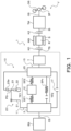
- FIG. 1 is a schematic configuration diagram showing a power transmission device 1 including a damper device 10 according to the first embodiment of the present disclosure.
- the power transmission device 1 shown in FIG. 1 is mounted on a vehicle V including an engine (internal combustion engine) EG that generates power by explosive combustion of a mixture of air and hydrocarbon fuel such as gasoline, light oil, and LPG.
- the power transmission device 1 can transmit power from the engine EG to a drive shaft DS. As shown in FIG.
- the power transmission device 1 in addition to the damper device 10 coupled to a crankshaft CS of the engine EG, the power transmission device 1 includes a motor generator MG, a transmission TM, a clutch K0 disposed between the damper device 10 and the motor generator MG, a clutch K2 disposed between the motor generator MG and the transmission TM, and a differential gear DF coupled to the transmission TM and the drive shaft DS.
- the motor generator MG is a three-phase synchronous generator motor coupled to a battery (not shown) via an inverter (not shown).
- the motor generator MG includes a stator S, and a rotor R that is coupled to the damper device 10 via the clutch K0 and that is coupled to the transmission TM via the clutch K2.
- the motor generator MG can be driven by electric power from a battery to output a drive torque to the transmission TM, and can also output a regenerative braking torque to the transmission TM during braking of the vehicle V. Electric power generated by the motor generator MG with the output of a regenerative braking torque is used for charging the battery and driving an auxiliary machine (not shown).
- the transmission TM is, for example, a 4-speed to 10-speed stepped transmission, and includes an input shaft (input member) IS that is coupled to the rotor R of the motor generator MG via the clutch K2, an intermediate shaft not shown that is coupled to the input shaft IS, an output shaft (output member) OS that is coupled to the differential gear DF via a gear mechanism not shown or that is directly coupled to the differential gear DF, at least one planetary gear mechanism for changing a power transmission path from the input shaft IS to the output shaft OS into a plurality of paths, a plurality of clutches and brakes (all not shown), and the like.
- the transmission TM may be, for example, a belt-type continuously variable transmission (CVT), a dual clutch transmission, or the like.
- the clutch K0 is, for example, a multi-plate type hydraulic clutch, and couples a transmission shaft TS, which is coupled to the damper device 10, and the rotor R of the motor generator MG, and also releases the coupling of the transmission shaft TS and the rotor R.
- the clutch K2 is, for example, a multi-plate type hydraulic clutch that couples the rotor R of the motor generator MG and the input shaft IS of the transmission TM and that releases the coupling of the rotor R and the input shaft IS.
- the clutches K0 and K2 may be a single plate type hydraulic clutch, or may be a dry type clutch such as a dog clutch or an electromagnetic clutch.
- the clutch K0 is released and the clutch K2 is engaged when the vehicle V starts.
- a drive torque from the motor generator MG driven by electric power from the battery can be output to the drive shaft DS via the transmission TM, the differential gear DF, etc. so as to start the vehicle V.
- the engine EG is cranked and started by a starter motor (not shown) in accordance with the satisfaction of an engine starting condition. Further, when an engagement condition of the clutch K0 is satisfied, the clutch K0 is gradually engaged by slip control.
- a drive torque can be output from the engine EG to the drive shaft DS via the damper device 10, the transmission TM, the differential gear DF, and the like.
- the battery in a state in which the clutch K2 is released and the clutch K0 is engaged, the battery can be charged by electric power from the motor generator MG that is driven by the engine EG to generate electricity.
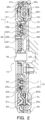
- the damper device 10 is configured as a dry damper, and as shown in FIGS. 1 and 2 , includes a drive plate (input element) 11, an intermediate member (intermediate element) 12, and a driven member (output element) 15, as rotation elements. Further, the damper device 10 includes, as torque transmission elements (torque transmission elastic bodies), a plurality of (for example, three in the present embodiment) first springs (input side elastic bodies) SP1 that transmits a torque between the drive member 11 and the intermediate member 12, a plurality of (for example, three in the present embodiment) second springs (output side elastic bodies) SP2 that acts in series on each corresponding first spring SP1 to transmit a torque between the intermediate member 12 and a driven member 15, and a plurality of (for example, three in the present embodiment) springs (second elastic bodies) SPx that can act in parallel and transmit a torque between the drive member 11 and the driven member 15.
- torque transmission elastic bodies a plurality of (for example, three in the present embodiment) first springs (input side
- an "axial direction” basically indicates an extending direction of a central axis (axial center) of the damper device 10.
- a "radial direction” is basically indicates the radial direction of the damper device 10 and a rotation element of the damper device 10 and the like, that is, the linear extending direction that extends from the central axis of the damper device 10 in a direction (radial direction) orthogonal to the central axis.
- a “circumferential direction” basically indicates a circumferential direction of the damper device 10 and the rotation element of the damper device 10, that is, a direction along a rotating direction of the rotation element.
- the plurality of first springs SP1, the intermediate member 12, and the plurality of second springs SP2 configure a first torque transmission path TP1 that transmits a torque between the drive member 11 and the driven member 15.
- coil springs having the same specifications (spring constants) as each other are adopted as the first and second springs SP1, SP2 of the first torque transmission path TP1.
- the plurality of springs SPx configure a second torque transmission path TP2 for transmitting a torque between the drive member 11 and the driven member 15.
- the second torque transmission path TP2 is provided in parallel with the first torque transmission path TP1.
- the plurality of springs SPx of the second torque transmission path TP2 acts in parallel with the first and second springs SP1, SP2 of the first torque transmission path TP1, after an input torque to the drive member 11 reaches a predetermined torque (first threshold) T1 that is smaller than a torque T2 (second threshold) corresponding to a maximum torsion angle ⁇ max of the damper device 10 and a torsion angle of the drive member 11 with respect to the driven member 15 becomes a predetermined angle ⁇ ref or more.
- first threshold predetermined torque
- second threshold torque corresponding to a maximum torsion angle ⁇ max of the damper device 10 and a torsion angle of the drive member 11 with respect to the driven member 15 becomes a predetermined angle ⁇ ref or more.
- the damper device 10 has a two-step (two-stage) damping characteristic.
- the first and second springs SP1, SP2 and the springs SPx a linear type coil spring made of a metal material spirally wound so as to have an axial center extending straight when no load is applied is adopted.
- the first and second springs SP1, SP2 and the springs SPx can be expanded and contracted more appropriately along the axial center, compared to the case in which an arc coil spring is used.
- an arc coil spring may be adopted as at least one of the first and second springs SP1, SP2 and the springs SPx.
- the drive member 11 of the damper device 10 includes a front cover 3 fixed to the crankshaft CS of the engine EG and a rear cover 21 integrated with the front cover 3.
- the front cover 3 is an annular member including an annular side wall portion and a short outer tubular portion extending in the axial direction from an outer periphery of the side wall portion.
- a plurality of bolt holes are provided on an inner peripheral portion of the front cover 3 (side wall portion), and the front cover 3 is fixed to the crankshaft CS via a plurality of bolts each inserted through a corresponding bolt hole and screwed to the crankshaft CS.
- the front cover 3 includes a plurality of (for example, three in the present embodiment) torque transmitting and receiving portions (elastic body contact portions) 3c.
- the plurality of torque transmitting and receiving portions 3c protrude from an outer peripheral side region of the front cover 3 in the same direction (axial direction) as the outer tubular portion at intervals (at equal intervals) in the circumferential direction.
- an external gear 30 that meshes with a pinion gear (not shown) attached to a rotation shaft of the starter motor described above is fixed to an outer peripheral portion of the front cover 3.
- the rear cover 21 is an annular member including an annular side wall portion and a short outer tubular portion extending in the axial direction from an outer periphery of the side wall portion, and has an inner radius larger than an inner radius of the front cover 3 (side wall portion).
- the outer tubular portion of the rear cover 21 is joined to the outer tubular portion of the front cover 3 by welding and thus, the front cover 3 and the rear cover 21 are integrated so that the side wall portions face each other at an interval.
- the rear cover 21 includes a plurality of (for example, three in the present embodiment) torque transmitting and receiving portions (elastic body contact portions) 21c.
- the plurality of torque transmitting and receiving portions 21c protrudes from an outer peripheral side region of the rear cover 21 in the same direction (axial direction) as the outer tubular portion at intervals (at equal intervals) in the circumferential direction, and each face the corresponding torque transmitting and receiving portion 3c of the front cover 3 at an interval in the axial direction.
- a plurality of (for example, three in the present embodiment) spring holding recess portions 21x is formed on an inner surface of a corner portion on the outer peripheral side of the rear cover 21 at intervals in the circumferential direction.
- Each spring holding recess portion 21x has a peripheral length corresponding to a natural length of the spring SPx, and holds the spring SPx from both sides as shown in FIG. 3 .
- a plurality of (for example, three in the present embodiment) spring supporting members 211 is fixed to the rear cover 21 by welding so as to be positioned radially inward of each corresponding spring holding recess portion 21x.
- the intermediate member 12 is an annular member disposed in the outer peripheral side region inside the front cover 3 and the rear cover 21.
- the intermediate member 12 has a plurality of (for example, three in the present embodiment) spring housing windows 12w and a plurality of (for example, three in the present embodiment) torque transmitting and receiving portions (elastic body contact portions) 12c that are each extended in an arc shape and that are disposed at intervals (at equal intervals) in the circumferential direction.
- One torque transmitting and receiving portion 12c is provided between the spring housing windows 12w adjacent to each other along the circumferential direction.
- the driven plate 25 is an annular member having an inner radius smaller than an outer radius of the damper hub 7 and an outer radius larger than an outer radius of the damper hub 7.
- the driven plate 25 is disposed so as to be offset in the axial direction from the plate portion of the damper hub 7 toward the rear cover 21 side, and is fixed to the outer peripheral portion of the damper hub 7 (plate portion) via a plurality of rivets.
- each torque transmitting and receiving portions 25c is offset in the axial direction from the inner peripheral portion of the driven plate 25 so that the torque transmitting and receiving portion 25c is positioned between the torque transmitting and receiving portions 3c of the front cover 3 and the torque transmitting and receiving portions 21c of the rear cover 21.
- the plurality of spring contact portions 25x is disposed so as to be arranged at intervals (at equal intervals) in the circumferential direction, and is each positioned on one side of the corresponding spring holding recess portion 21x of the rear cover 21 in the circumferential direction.
- a plurality of internal teeth 25tr is formed on an inner periphery of the driven plate 25.
- the plurality of internal teeth 25tr may be formed on the entire inner circumference of the driven plate 25, and a plurality of internal teeth 25tr may be formed at set positions at intervals (at equal intervals) in the circumferential direction on the inner circumference of the driven plate 25.
- each spring SPx In the mounted state of the damper device 10, one end portion of each spring SPx is in contact with a spring contact portion formed on one side of the corresponding spring holding recess portion 21x, and the other end portion of each spring SPx is in contact with a spring contact portion formed on the other side of the corresponding spring holding recess portion 21x, while being separated from the corresponding spring contact portion 25x of the driven plate 25 in the circumferential direction.
- the damper device 10 includes a stopper 17 that restricts a relative rotation between the drive member 11 and the driven member 15.
- the stopper 17 restricts a relative rotation between the drive member 11 and a driven plate 15, and all deflections of the first and second springs SP1, SP2 and the springs SPx are restricted accordingly.
- the gear member 221 and the spacer 222 are rotatably supported by the outer peripheral surface of the inner tubular portion of the damper hub 7 via a washer 224 made of resin. As shown in FIG. 2 , a plurality of work holes used when coupling the front cover 3 to the crankshaft CS with bolts is formed in the gear member 221, the spacer 222, and the damper hub 7.
- a resin sheet or the like is disposed between two members that rotate relative to each other.
- a drive torque from the engine EG is transmitted to the drive member 11, that is, the front cover 3 and the rear cover 21.
- a torque (average torque) transmitted from the engine EG to the drive member 11 is transmitted to the driven member 15 via the first torque transmission path TP1 including the plurality of first springs SP1, the intermediate member 12, and the plurality of second springs SP2, until the input torque reaches the torque T1 described above.
- a torque transmitted to the driven member 15 is transmitted to the drive shaft DS via the transmission shaft TS, the clutch K0, the rotor R of the motor generator MG, the clutch K2, the transmission TM, the differential gear DF, and the like.
- the sun gear 22 is accelerated by the action of the planetary gear mechanism PG, and rotates at a rotation speed higher than that of the rear cover 21, that is, the drive member 11.
- an inertial torque is applied from the sun gear 22, which is the mass body of the rotary inertia mass damper 20, to the driven plate 25, that is, the driven member 15, which is the output element of the damper device 10, via the pinion gear 23 and vibration of the driven member 15 can be dampened.
- the rotary inertia mass damper 20 mainly transmits an inertial torque between the drive member 11 and the driven member 15, and does not transmit an average torque.
- a torque (average torque) transmitted from the plurality of second springs SP2 (first torque transmission path TP1) to the driven member 15 depends on (is proportional to) a displacement (a deflection amount, that is, a torsion angle) of the second spring SP2 between the intermediate member 12 and the driven member 15.
- a torque (inertial torque) transmitted from the rotary inertia mass damper 20 to the driven member 15 depends on (is proportional to) the difference in angular acceleration between the drive member 11 and the driven member 15, that is, a two-time differential value of the displacement of the first and second springs SP1, SP2 between the drive member 11 and the driven member 15.
- a phase of the vibration transmitted from the drive member 11 to the driven member 15 via the plurality of second springs SP2 and a phase of the vibration transmitted from the drive member 11 to the driven member 15 via the rotary inertia mass damper 20 are deviated by 180°.
- the damper device 10 it is possible to satisfactorily dampen the vibration of the driven member 15 by having one of the vibration transmitted from the plurality of second springs SP2 to the driven member 15 and the vibration transmitted from the rotary inertia mass damper 20 to the driven member 15 cancel out at least a part of the other one.
- two natural frequencies are set for a state in which deflection of the first and second springs SP1, SP2 is allowed and the springs SPx are not deflected. That is, in the first torque transmission path TP1, when deflection of the first and second springs SP1, SP2 is allowed, the springs SPx are not deflected, and a rotation speed Ne of the engine EG (a rotation speed of the drive member 11) is extremely low, for example, resonance (first resonance) occurs due to the drive member 11 and the driven member 15 vibrating in opposite phases to each other.
- the driven member 15 of the damper device 10 that is, the damper hub 7 and the driven plate 25 are coupled to the rotor R of the motor generator MG via the transmission shaft TS and the clutch K0, and the rotor R is coupled to the input shaft IS of the transmission TM via the clutch K2.
- the rotary inertia mass damper 20 including the planetary gear mechanism PG due to a characteristic of the rotary inertia mass damper 20 including the planetary gear mechanism PG, while the moment of inertia larger than the total value of the moment of inertia of the plurality of pinion gears 23 and the sun gear 22 serving as the mass body is applied to the rear cover 21 serving as a carrier, that is, the drive member 11, the moment of inertia of the driven plate 25 serving as the ring gear, that is, the driven member 15 can be decreased.
- the moment of inertia of the sun gear 22 including the gear member 221 is set as "Js”
- the total value of the moment of inertia of the plurality of pinion gears 23 is set as "Jp”
- a gear ratio of the planetary gear mechanism PG (the number of teeth of the sun gear 22 (external teeth 22t) divided by the number of teeth of the internal teeth 25tr) is set as " ⁇ ”
- a moment of inertia Ji distributed to the drive member 11 by the planetary gear mechanism PG and the moment of inertia Jo distributed to the driven member 15 by the planetary gear mechanism PG is expressed by the following equations (1) and (2).
- the moment of inertia Js of the sun gear 22 is sufficiently larger than the total value Jp of the moment of inertia of the plurality of pinion gears 23, and the moment of inertia Ji distributed to the drive member 11 becomes a positive value larger than the total value (Js + Jp) of the moment of inertia of the sun gear 22 and the plurality of pinion gears 23.
- the moment of inertia Js of the sun gear 22 serving as the mass body of the rotary inertia mass damper 20, etc., the moment of inertia Jp of the plurality of pinion gears 23, and the gear ratio ⁇ of the planetary gear mechanism PG are set such that the moment of inertia Jo distributed to the driven member 15 by the planetary gear mechanism PG becomes a negative value. Further, the moment of inertia Js, the moment of inertia Jp, and the gear ratio ⁇ are preferably set so as to satisfy Jo + Jm ⁇ 0 when the moment of inertia of the rotor R of the motor generator MG is "Jm".
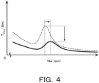
- the vibration (inertial torque) having a opposite phase of the vibration transmitted from the second springs SP2 to the driven member 15 can be transmitted from the rotary inertia mass damper 20 to the driven member 15, and as shown by a solid line in FIG. 4 , the torque fluctuation T Fluc due to the shaft resonance can be decreased by the vibration transmitted from the rotary inertia mass damper 20 to the driven member 15.
- the level of the shaft resonance decreases as the frequency, that is, the rotation speed of the input shaft IS increases.
- a damper device configured such that a part of the drive member 11 functions as a ring gear and a part of the driven member 15 functions as a carrier, and the sun gear 22 functions as a mass body
- the moment of inertia distributed to the drive member 11 by the planetary gear mechanism PG is represented by the above equation (2)
- the moment of inertia distributed to the driven member 15 by the planetary gear mechanism PG is represented by the above equation (1).
- the driven plate 25 that is a part of the driven member 15 functions as a ring gear
- the sun gear 22 functions as a mass body
- the first and second springs SP1, SP2 are disposed radially outward of the plurality of pinion gears 23. This makes it possible to reduce the rigidity of the first and second springs SP1, SP2 (the combined springs of the first and second springs SP1, SP2) and further improve the vibration damping performance of the damper device 10.
- the plurality of springs SPx may be disposed so as to be adjacent to the plurality of pinion gears 23 in the circumferential direction on an inner side of the first and second springs SP1, SP2 in the radial direction of the damper device 10.
- the damper device 10 can be made compact.
- the first torque transmission path TP1 may be configured by a plurality of (for example, six) springs SP that can act in parallel with each other between the drive member 11 and the driven member 15 so as to transmit a torque.
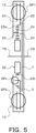
- the moment of inertia Ji distributed to the drive member 11 is always a positive value larger than the total value (Jr + Jp) of the moment of inertia of the ring gear 27 and the moment of inertia of the plurality of pinion gears 23.
- the damper device 10B it is possible to suppress an increase in the moment of inertia (total value) of the input shaft IS of the transmission TM that rotates integrally with the driven member 15B and the rotor R of the motor generator MG, that is, it is possible to suppress a decrease in the frequency of the shaft resonance.
- the vibration (inertial torque) having a opposite phase of the vibration transmitted from the second springs SP2 to the driven member 15B can be transmitted from the rotary inertia mass damper 20B to the driven member 15B, the torque fluctuation T Fluc due to the shaft resonance can be decreased by the vibration transmitted from the rotary inertia mass damper 20B to the driven member 15B.
- the damper device 10B it is possible to satisfactorily suppress the shaft resonance of the transmission TM from being generated in a relatively low rotation range and becoming apparent.
- a damper device configured such that a part of the drive member 11 functions as a sun gear and a part of the driven member 15B functions as a carrier, and the ring gear 27 functions as a mass body
- the moment of inertia distributed to the drive member 11 by the planetary gear mechanism PG' is represented by the above equation (4)
- the moment of inertia distributed to the driven member 15B by the planetary gear mechanism PG' is represented by the above equation (3).
- the plurality of springs SPx may be disposed on the inner side of the first and second springs SP1, SP2 in the radial direction of the damper device 10B.
- the first torque transmission path TP1 of the damper device 10B may be configured by a plurality of (for example, six) springs SP that can act in parallel with each other between the drive member 11 and the driven member 15B so as to transmit a torque.
- the output element is coupled to the rotor of the electric motor
- the input shaft of the transmission is coupled to rotor of the electric motor.
- the damper device of the present disclosure is configured such that a part of the input element functions as a carrier of the planetary gear mechanism (rotary inertia mass damper), and a part of the output element functions as one of the sun gear and the ring gear.
- a characteristic of the rotary inertia mass damper including the planetary gear mechanism while the moment of inertia larger than the total value of the moment of inertia of the plurality of pinion gears and the other of the sun gear and the ring gear serving as the mass body is applied to the carrier, that is, the input element, the moment of inertia of the one of the sun gear and the ring gear, that is, the output element can be decreased.
- the damper device of the present disclosure it is possible to transmit, from the rotary inertia mass damper to the output element, the vibration (inertial torque) having an opposite phase of the vibration transmitted from the elastic body to the output element, and the torque fluctuation resulting from the shaft resonance can be decreased with the vibration transmitted from the rotary inertia mass damper to the output element.
- the damper device of the present disclosure it is possible to satisfactorily suppress the shaft resonance of the transmission from being generated in a relatively low rotation range and becoming apparent.
- the ring gear (25) may be a part of the output element (15), the sun gear (22) may function as the mass body, and the elastic body (SP1, SP2, SP) may be disposed on an outer side of the plurality of pinion gears (23) in a radial direction of the damper device (10). This makes it possible to reduce the rigidity of the elastic body and further improve the vibration damping performance of the damper device.
- the input element (11) including the carrier (21) may be formed so as to surround the elastic body (SP1, SP2, SP), the ring gear (25), and the plurality of pinion gears (23).
- the carrier (21) may be formed in an annular shape
- the sun gear (22) may include a gear member (221) having external teeth (22t) that mesh with gear teeth (23t) of the plurality of pinion gears (23), and an annular member (223) that is disposed on an outer side of the carrier (21) in an axial direction of the damper device (10) and that is coupled to the gear member (221) on an inner side of the carrier (21) in a radial direction of the damper device (10).
- the moment of inertia of the sun gear serving as a mass body can be made larger, the vibration damping performance of the rotary inertia mass damper can be improved, and the moment of inertia (total value) of the input shaft of the transmission can be increased, that is, a decrease in the frequency of the shaft resonance can be satisfactorily suppressed.
- a moment of inertia of the mass body (22, 27), a moment of inertia of the plurality of pinion gears (23), and a gear ratio ( ⁇ ) of the planetary gear mechanism (PG, PG') may be set such that a moment of inertia distributed to the output element (15, 15B) by the planetary gear mechanism (PG, PG') is a negative value.
- the invention of the present disclosure can be used in a manufacturing field of a damper device and the like.
Landscapes
- Engineering & Computer Science (AREA)
- General Engineering & Computer Science (AREA)
- Mechanical Engineering (AREA)
- Physics & Mathematics (AREA)
- Acoustics & Sound (AREA)
- Aviation & Aerospace Engineering (AREA)
- Retarders (AREA)
Claims (15)
- Dispositif amortisseur (10, 10B) comprenant :un élément d'entrée (11) auquel un couple de rotation provenant d'un moteur (EG) est transmis ;un élément de sortie (15, 15B) ;un corps élastique (SP1, SP2, SP) qui transmet un couple de rotation entre l'élément d'entrée (11) et l'élément de sortie (15, 15B) ; etun amortisseur à masse d'inertie rotative (20, 20B) présentant un corps de masse qui tourne conformément à une rotation relative de l'élément d'entrée (11) et de l'élément de sortie (15, 15B), dans lequell'élément de sortie (15, 15B) est configuré pour être couplé à un rotor (R) d'un moteur-générateur électrique (MG),le rotor (R) du moteur-générateur électrique (MG) est couplé à un arbre d'entrée (IS) d'une transmission (TM),l'amortisseur à masse d'inertie rotative inclut un mécanisme de train planétaire (PG, PG') présentant un planétaire (22, 25B), une couronne (25, 27), une pluralité de pignons (23) et un support (21) qui supporte la pluralité de pignons (23), etle support (21) est une partie de l'élément d'entrée (11), l'un du planétaire (25B) et de la couronne (25) est une partie de l'élément de sortie (15, 15B), et l'autre du planétaire (22) et de la couronne (27) fait office de corps de masse,caractérisé en ce queun moment d'inertie supérieur à une valeur totale d'un moment d'inertie de la pluralité de pignons et du corps de masse est appliqué à l'élément d'entrée (11), et un moment d'inertie de l'élément de sortie (15, 15B) est une valeur négative.
- Dispositif amortisseur (10, 10B) selon la revendication 1, dans lequella couronne (25) fait partie de l'élément de sortie (15),le planétaire (22) fait office de corps de masse, etle corps élastique (SP1, SP2, SP) est disposé sur un côté extérieur de la pluralité de pignons (23) dans une direction radiale du dispositif amortisseur (10).
- Dispositif amortisseur (10, 10B) selon la revendication 2, dans lequel l'élément d'entrée (11) incluant le support (21) est formé de manière à entourer le corps élastique (SP1, SP2, SP), la couronne (25) et la pluralité de pignons (23).
- Dispositif amortisseur (10, 10B) selon la revendication 3, dans lequelle support (21) présente une forme annulaire, etle planétaire (22) inclut un élément d'engrenage (221) présentant des dents externes (22t) qui s'engrènent avec des dents d'engrenage (23t) de la pluralité de pignons (23), et un élément annulaire (223) qui est disposé sur un côté extérieur du support (21) dans une direction axiale du dispositif amortisseur (10) et qui est couplé à l'élément d'engrenage (221) sur un côté intérieur du support (21) dans une direction radiale du dispositif amortisseur (10).
- Dispositif amortisseur (10, 10B) selon la revendication 3 ou 4, dans lequel le support (21) inclut une partie de transmission et de réception de couple de rotation (21c), qui transmet et reçoit un couple de rotation vers et depuis le corps élastique (SP1, SP2, SP) correspondant, et supporte une extrémité d'une pluralité d'arbres de pignon (24), chacun inséré à travers le pignon (23) sur un côté intérieur de la partie de transmission et de réception de couple de rotation (21c) dans la direction radiale du dispositif amortisseur (10).
- Dispositif amortisseur (10, 10B) selon la revendication 1, dans lequelle planétaire (25B) fait partie de l'élément de sortie (15B),la couronne (27) fait office de corps de masse, etle corps élastique (SP1, SP2, SP) est disposé sur un côté intérieur de la pluralité de pignons (23) dans une direction radiale du dispositif amortisseur (10B).
- Dispositif amortisseur (10, 10B) selon la revendication 6, dans lequel l'élément d'entrée (11) incluant le support (21) est formé de manière à entourer le corps élastique (SP1, SP2, SP), la couronne (27) et la pluralité de pignons.
- Dispositif amortisseur (10, 10B) selon l'une quelconque des revendications 1 à 7, dans lequelle dispositif amortisseur (10, 10B) présente en outre un élément intermédiaire (12), etle corps élastique (SP1, SP2, SP) inclut un corps élastique côté entrée (SP1) qui transmet un couple de rotation entre l'élément d'entrée (11) et l'élément intermédiaire (12), et un corps élastique côté sortie (SP2) qui transmet un couple de rotation entre l'élément intermédiaire (12) et l'élément de sortie (15, 15B).
- Dispositif amortisseur (10, 10B) selon l'une quelconque des revendications 1 à 8, dans lequel le dispositif amortisseur (10, 10B) inclut en outre un second corps élastique (SPx) qui agit en parallèle avec le corps élastique (SP1, SP2, SP) lorsqu'un couple de rotation transmis entre l'élément d'entrée (11) et l'élément de sortie (15, 15B) est égal ou supérieur à une valeur prédéterminée (T1).
- Dispositif amortisseur (10, 10B) selon la revendication 9, dans lequel le second corps élastique (SPx) est disposé sur un côté extérieur du corps élastique (SP1, SP2, SP) dans une direction radiale du dispositif amortisseur (10, 10B).
- Dispositif amortisseur (10, 10B) selon la revendication 9, dans lequel le second corps élastique (SPx) est disposé sur un côté intérieur du corps élastique (SP1, SP2, SP) dans une direction radiale du dispositif amortisseur (10, 10B).
- Dispositif amortisseur (10, 10B) selon la revendication 9, dans lequel le second corps élastique est disposé de manière à chevaucher au moins partiellement le corps élastique lorsqu'il est vu dans une direction radiale du dispositif amortisseur (10, 10B).
- Dispositif amortisseur (10, 10B) selon la revendication 10 ou 11, dans lequel le second corps élastique (SPx) est disposé de manière à être adjacent à la pluralité de pignons (23) dans une direction circonférentielle.
- Dispositif amortisseur (10, 10B) selon l'une quelconque des revendications 1 à 13, dans lequel un embrayage (K0, K2) est disposé entre le dispositif amortisseur (10, 10B) et le moteur-générateur électrique (MG) et entre le moteur-générateur électrique (MG) et la transmission (TM).
- Dispositif amortisseur (10, 10B) selon l'une quelconque des revendications 1 à 14, dans lequel le moment d'inertie du corps de masse, un moment d'inertie de la pluralité de pignons (23) et un rapport de transmission (λ) du mécanisme de train planétaire (PG, PG') sont réglés de telle sorte que le moment d'inertie distribué à l'élément de sortie (15, 15B) par le mécanisme de train planétaire (PG, PG') soit une valeur négative.
Applications Claiming Priority (2)
| Application Number | Priority Date | Filing Date | Title |
|---|---|---|---|
| JP2018242829 | 2018-12-26 | ||
| PCT/JP2019/051295 WO2020138361A1 (fr) | 2018-12-26 | 2019-12-26 | Dispositif amortisseur |
Publications (4)
| Publication Number | Publication Date |
|---|---|
| EP3904723A1 EP3904723A1 (fr) | 2021-11-03 |
| EP3904723A4 EP3904723A4 (fr) | 2022-03-30 |
| EP3904723B1 true EP3904723B1 (fr) | 2025-06-25 |
| EP3904723B8 EP3904723B8 (fr) | 2025-09-03 |
Family
ID=71128811
Family Applications (1)
| Application Number | Title | Priority Date | Filing Date |
|---|---|---|---|
| EP19901966.2A Active EP3904723B8 (fr) | 2018-12-26 | 2019-12-26 | Dispositif amortisseur |
Country Status (5)
| Country | Link |
|---|---|
| US (1) | US12006997B2 (fr) |
| EP (1) | EP3904723B8 (fr) |
| JP (1) | JP7198289B2 (fr) |
| CN (1) | CN113272576B (fr) |
| WO (1) | WO2020138361A1 (fr) |
Families Citing this family (1)
| Publication number | Priority date | Publication date | Assignee | Title |
|---|---|---|---|---|
| US12498022B2 (en) * | 2019-05-15 | 2025-12-16 | The Regents Of The University Of California | Lossless continuously adjustable devices |
Family Cites Families (12)
| Publication number | Priority date | Publication date | Assignee | Title |
|---|---|---|---|---|
| DE19609042C2 (de) | 1996-03-08 | 1998-10-15 | Mannesmann Sachs Ag | Schwungmassenanordnung mit einem Planetengetriebe |
| CN103221714B (zh) * | 2010-11-19 | 2015-07-29 | 丰田自动车株式会社 | 车辆用减振装置 |
| JP2014184923A (ja) | 2013-03-25 | 2014-10-02 | Toyota Motor Corp | 車両用動力伝達装置 |
| JP6336291B2 (ja) * | 2014-02-19 | 2018-06-06 | ユニプレス株式会社 | ダイナミックダンパ及び動力伝達軸の回転変動抑制装置 |
| JP6301158B2 (ja) | 2014-02-27 | 2018-03-28 | 株式会社エクセディ | ダンパー装置 |
| JP6264998B2 (ja) * | 2014-03-27 | 2018-01-24 | アイシン精機株式会社 | ダンパ |
| JP6250841B2 (ja) | 2014-12-25 | 2017-12-20 | アイシン・エィ・ダブリュ工業株式会社 | ダンパ装置 |
| US9505446B2 (en) * | 2015-04-15 | 2016-11-29 | Toyota Jidosha Kabushiki Kaisha | Powertrain unit |
| US10677313B2 (en) | 2015-06-26 | 2020-06-09 | Aisin Aw Industries Co., Ltd. | Damper device |
| JP2018071624A (ja) | 2016-10-27 | 2018-05-10 | アイシン・エィ・ダブリュ工業株式会社 | ダンパ装置 |
| JP6384573B1 (ja) * | 2017-03-08 | 2018-09-05 | トヨタ自動車株式会社 | 捩り振動低減装置 |
| JP7056336B2 (ja) * | 2018-04-09 | 2022-04-19 | トヨタ自動車株式会社 | ハイブリッド車両 |
-
2019
- 2019-12-26 CN CN201980081840.6A patent/CN113272576B/zh active Active
- 2019-12-26 JP JP2020562453A patent/JP7198289B2/ja active Active
- 2019-12-26 EP EP19901966.2A patent/EP3904723B8/fr active Active
- 2019-12-26 US US17/413,620 patent/US12006997B2/en active Active
- 2019-12-26 WO PCT/JP2019/051295 patent/WO2020138361A1/fr not_active Ceased
Also Published As
| Publication number | Publication date |
|---|---|
| CN113272576B (zh) | 2024-10-18 |
| JP7198289B2 (ja) | 2022-12-28 |
| US20220042573A1 (en) | 2022-02-10 |
| EP3904723B8 (fr) | 2025-09-03 |
| EP3904723A4 (fr) | 2022-03-30 |
| US12006997B2 (en) | 2024-06-11 |
| WO2020138361A1 (fr) | 2020-07-02 |
| JPWO2020138361A1 (ja) | 2021-10-14 |
| EP3904723A1 (fr) | 2021-11-03 |
| CN113272576A (zh) | 2021-08-17 |
Similar Documents
| Publication | Publication Date | Title |
|---|---|---|
| US8991531B2 (en) | Hybrid drive module | |
| JP5561375B2 (ja) | 車両用ダンパ装置 | |
| JP6462874B2 (ja) | ダンパ装置 | |
| US11149817B2 (en) | Damper device | |
| US9797470B2 (en) | Torsional vibration damper and torsional vibration damping method | |
| WO2012066679A1 (fr) | Dispositif d'amortissement de véhicule | |
| JP6609028B2 (ja) | ダンパ装置 | |
| CN107709829B (zh) | 阻尼器装置 | |
| CN107850181A (zh) | 阻尼器装置 | |
| KR20150112992A (ko) | 차량의 파워 트레인용 비틀림 진동 댐핑 장치 | |
| JP2018040475A (ja) | ダンパ装置 | |
| JP5585377B2 (ja) | トルクリミッタ機構を備えたダンパ装置 | |
| EP3904723B1 (fr) | Dispositif amortisseur | |
| EP3348858B1 (fr) | Dispositif amortisseur | |
| US20220205491A1 (en) | Damper device | |
| JP5673460B2 (ja) | 車両用ダンパ装置 | |
| JP7631938B2 (ja) | ハイブリッド車両の動力伝達装置 | |
| JP7567590B2 (ja) | ハイブリッド車両の動力伝達装置 | |
| WO2020230651A1 (fr) | Appareil amortisseur | |
| US20180208041A1 (en) | Vehicle drive device | |
| JP2022144138A (ja) | ハイブリッド車両の動力伝達装置 | |
| WO2001096759A2 (fr) | Embrayage a huile a deux masses |
Legal Events
| Date | Code | Title | Description |
|---|---|---|---|
| STAA | Information on the status of an ep patent application or granted ep patent |
Free format text: STATUS: THE INTERNATIONAL PUBLICATION HAS BEEN MADE |
|
| PUAI | Public reference made under article 153(3) epc to a published international application that has entered the european phase |
Free format text: ORIGINAL CODE: 0009012 |
|
| STAA | Information on the status of an ep patent application or granted ep patent |
Free format text: STATUS: REQUEST FOR EXAMINATION WAS MADE |
|
| 17P | Request for examination filed |
Effective date: 20210519 |
|
| AK | Designated contracting states |
Kind code of ref document: A1 Designated state(s): AL AT BE BG CH CY CZ DE DK EE ES FI FR GB GR HR HU IE IS IT LI LT LU LV MC MK MT NL NO PL PT RO RS SE SI SK SM TR |
|
| RAP3 | Party data changed (applicant data changed or rights of an application transferred) |
Owner name: AISIN CORPORATION Owner name: AISIN AW INDUSTRIES CO., LTD. |
|
| A4 | Supplementary search report drawn up and despatched |
Effective date: 20220225 |
|
| RIC1 | Information provided on ipc code assigned before grant |
Ipc: F16F 15/31 20060101ALN20220221BHEP Ipc: F16H 1/28 20060101ALI20220221BHEP Ipc: F16F 15/134 20060101ALI20220221BHEP Ipc: F16F 15/131 20060101AFI20220221BHEP |
|
| DAV | Request for validation of the european patent (deleted) | ||
| DAX | Request for extension of the european patent (deleted) | ||
| REG | Reference to a national code |
Ref legal event code: R079 Free format text: PREVIOUS MAIN CLASS: F16H0001280000 Ref country code: DE Ref document number: 602019071756 Country of ref document: DE Ipc: F16F0015131000 |
|
| RIC1 | Information provided on ipc code assigned before grant |
Ipc: F16F 15/31 20060101ALN20241116BHEP Ipc: F16H 1/28 20060101ALI20241116BHEP Ipc: F16F 15/134 20060101ALI20241116BHEP Ipc: F16F 15/131 20060101AFI20241116BHEP |
|
| GRAP | Despatch of communication of intention to grant a patent |
Free format text: ORIGINAL CODE: EPIDOSNIGR1 |
|
| STAA | Information on the status of an ep patent application or granted ep patent |
Free format text: STATUS: GRANT OF PATENT IS INTENDED |
|
| RIC1 | Information provided on ipc code assigned before grant |
Ipc: F16F 15/31 20060101ALN20241219BHEP Ipc: F16H 1/28 20060101ALI20241219BHEP Ipc: F16F 15/134 20060101ALI20241219BHEP Ipc: F16F 15/131 20060101AFI20241219BHEP |
|
| INTG | Intention to grant announced |
Effective date: 20250117 |
|
| GRAS | Grant fee paid |
Free format text: ORIGINAL CODE: EPIDOSNIGR3 |
|
| GRAA | (expected) grant |
Free format text: ORIGINAL CODE: 0009210 |
|
| STAA | Information on the status of an ep patent application or granted ep patent |
Free format text: STATUS: THE PATENT HAS BEEN GRANTED |
|
| AK | Designated contracting states |
Kind code of ref document: B1 Designated state(s): AL AT BE BG CH CY CZ DE DK EE ES FI FR GB GR HR HU IE IS IT LI LT LU LV MC MK MT NL NO PL PT RO RS SE SI SK SM TR |
|
| RAP3 | Party data changed (applicant data changed or rights of an application transferred) |
Owner name: AISIN CORPORATION Owner name: AISIN AW INDUSTRIES CO., LTD |
|
| REG | Reference to a national code |
Ref country code: GB Ref legal event code: FG4D |
|
| REG | Reference to a national code |
Ref country code: CH Ref legal event code: EP |
|
| REG | Reference to a national code |
Ref country code: CH Ref legal event code: EP |
|
| REG | Reference to a national code |
Ref country code: IE Ref legal event code: FG4D |
|
| REG | Reference to a national code |
Ref country code: DE Ref legal event code: R096 Ref document number: 602019071756 Country of ref document: DE |
|
| REG | Reference to a national code |
Ref country code: CH Ref legal event code: PK Free format text: BERICHTIGUNG B8 |
|
| RAP4 | Party data changed (patent owner data changed or rights of a patent transferred) |
Owner name: AISIN AW INDUSTRIES CO., LTD Owner name: AISIN CORPORATION |
|
| PG25 | Lapsed in a contracting state [announced via postgrant information from national office to epo] |
Ref country code: FI Free format text: LAPSE BECAUSE OF FAILURE TO SUBMIT A TRANSLATION OF THE DESCRIPTION OR TO PAY THE FEE WITHIN THE PRESCRIBED TIME-LIMIT Effective date: 20250625 |
|
| REG | Reference to a national code |
Ref country code: LT Ref legal event code: MG9D |
|
| PG25 | Lapsed in a contracting state [announced via postgrant information from national office to epo] |
Ref country code: NO Free format text: LAPSE BECAUSE OF FAILURE TO SUBMIT A TRANSLATION OF THE DESCRIPTION OR TO PAY THE FEE WITHIN THE PRESCRIBED TIME-LIMIT Effective date: 20250925 Ref country code: GR Free format text: LAPSE BECAUSE OF FAILURE TO SUBMIT A TRANSLATION OF THE DESCRIPTION OR TO PAY THE FEE WITHIN THE PRESCRIBED TIME-LIMIT Effective date: 20250926 |
|
| PG25 | Lapsed in a contracting state [announced via postgrant information from national office to epo] |
Ref country code: BG Free format text: LAPSE BECAUSE OF FAILURE TO SUBMIT A TRANSLATION OF THE DESCRIPTION OR TO PAY THE FEE WITHIN THE PRESCRIBED TIME-LIMIT Effective date: 20250625 |
|
| PG25 | Lapsed in a contracting state [announced via postgrant information from national office to epo] |
Ref country code: HR Free format text: LAPSE BECAUSE OF FAILURE TO SUBMIT A TRANSLATION OF THE DESCRIPTION OR TO PAY THE FEE WITHIN THE PRESCRIBED TIME-LIMIT Effective date: 20250625 |
|
| PG25 | Lapsed in a contracting state [announced via postgrant information from national office to epo] |
Ref country code: RS Free format text: LAPSE BECAUSE OF FAILURE TO SUBMIT A TRANSLATION OF THE DESCRIPTION OR TO PAY THE FEE WITHIN THE PRESCRIBED TIME-LIMIT Effective date: 20250925 |
|
| PG25 | Lapsed in a contracting state [announced via postgrant information from national office to epo] |
Ref country code: LV Free format text: LAPSE BECAUSE OF FAILURE TO SUBMIT A TRANSLATION OF THE DESCRIPTION OR TO PAY THE FEE WITHIN THE PRESCRIBED TIME-LIMIT Effective date: 20250625 |
|
| REG | Reference to a national code |
Ref country code: NL Ref legal event code: MP Effective date: 20250625 |
|
| PG25 | Lapsed in a contracting state [announced via postgrant information from national office to epo] |
Ref country code: NL Free format text: LAPSE BECAUSE OF FAILURE TO SUBMIT A TRANSLATION OF THE DESCRIPTION OR TO PAY THE FEE WITHIN THE PRESCRIBED TIME-LIMIT Effective date: 20250625 |
|
| PG25 | Lapsed in a contracting state [announced via postgrant information from national office to epo] |
Ref country code: PT Free format text: LAPSE BECAUSE OF FAILURE TO SUBMIT A TRANSLATION OF THE DESCRIPTION OR TO PAY THE FEE WITHIN THE PRESCRIBED TIME-LIMIT Effective date: 20251027 |
|
| REG | Reference to a national code |
Ref country code: AT Ref legal event code: MK05 Ref document number: 1806718 Country of ref document: AT Kind code of ref document: T Effective date: 20250625 |
|
| PG25 | Lapsed in a contracting state [announced via postgrant information from national office to epo] |
Ref country code: IS Free format text: LAPSE BECAUSE OF FAILURE TO SUBMIT A TRANSLATION OF THE DESCRIPTION OR TO PAY THE FEE WITHIN THE PRESCRIBED TIME-LIMIT Effective date: 20251025 |
|
| PGFP | Annual fee paid to national office [announced via postgrant information from national office to epo] |
Ref country code: DE Payment date: 20251028 Year of fee payment: 7 |
|
| PGFP | Annual fee paid to national office [announced via postgrant information from national office to epo] |
Ref country code: GB Payment date: 20251114 Year of fee payment: 7 |
|
| PG25 | Lapsed in a contracting state [announced via postgrant information from national office to epo] |
Ref country code: AT Free format text: LAPSE BECAUSE OF FAILURE TO SUBMIT A TRANSLATION OF THE DESCRIPTION OR TO PAY THE FEE WITHIN THE PRESCRIBED TIME-LIMIT Effective date: 20250625 Ref country code: SM Free format text: LAPSE BECAUSE OF FAILURE TO SUBMIT A TRANSLATION OF THE DESCRIPTION OR TO PAY THE FEE WITHIN THE PRESCRIBED TIME-LIMIT Effective date: 20250625 |
|
| PGFP | Annual fee paid to national office [announced via postgrant information from national office to epo] |
Ref country code: FR Payment date: 20251117 Year of fee payment: 7 |
|
| PG25 | Lapsed in a contracting state [announced via postgrant information from national office to epo] |
Ref country code: CZ Free format text: LAPSE BECAUSE OF FAILURE TO SUBMIT A TRANSLATION OF THE DESCRIPTION OR TO PAY THE FEE WITHIN THE PRESCRIBED TIME-LIMIT Effective date: 20250625 |
|
| PG25 | Lapsed in a contracting state [announced via postgrant information from national office to epo] |
Ref country code: PL Free format text: LAPSE BECAUSE OF FAILURE TO SUBMIT A TRANSLATION OF THE DESCRIPTION OR TO PAY THE FEE WITHIN THE PRESCRIBED TIME-LIMIT Effective date: 20250625 |
|
| PG25 | Lapsed in a contracting state [announced via postgrant information from national office to epo] |
Ref country code: SK Free format text: LAPSE BECAUSE OF FAILURE TO SUBMIT A TRANSLATION OF THE DESCRIPTION OR TO PAY THE FEE WITHIN THE PRESCRIBED TIME-LIMIT Effective date: 20250625 |
|
| PG25 | Lapsed in a contracting state [announced via postgrant information from national office to epo] |
Ref country code: ES Free format text: LAPSE BECAUSE OF FAILURE TO SUBMIT A TRANSLATION OF THE DESCRIPTION OR TO PAY THE FEE WITHIN THE PRESCRIBED TIME-LIMIT Effective date: 20250625 |
|
| PG25 | Lapsed in a contracting state [announced via postgrant information from national office to epo] |
Ref country code: RO Free format text: LAPSE BECAUSE OF FAILURE TO SUBMIT A TRANSLATION OF THE DESCRIPTION OR TO PAY THE FEE WITHIN THE PRESCRIBED TIME-LIMIT Effective date: 20250625 |
|
| PG25 | Lapsed in a contracting state [announced via postgrant information from national office to epo] |
Ref country code: DK Free format text: LAPSE BECAUSE OF FAILURE TO SUBMIT A TRANSLATION OF THE DESCRIPTION OR TO PAY THE FEE WITHIN THE PRESCRIBED TIME-LIMIT Effective date: 20250625 |
|
| PG25 | Lapsed in a contracting state [announced via postgrant information from national office to epo] |
Ref country code: IT Free format text: LAPSE BECAUSE OF FAILURE TO SUBMIT A TRANSLATION OF THE DESCRIPTION OR TO PAY THE FEE WITHIN THE PRESCRIBED TIME-LIMIT Effective date: 20250625 |
|
| PLBE | No opposition filed within time limit |
Free format text: ORIGINAL CODE: 0009261 |
|
| STAA | Information on the status of an ep patent application or granted ep patent |
Free format text: STATUS: NO OPPOSITION FILED WITHIN TIME LIMIT |