EP3904937A1 - Système de microscope - Google Patents
Système de microscope Download PDFInfo
- Publication number
- EP3904937A1 EP3904937A1 EP19906490.8A EP19906490A EP3904937A1 EP 3904937 A1 EP3904937 A1 EP 3904937A1 EP 19906490 A EP19906490 A EP 19906490A EP 3904937 A1 EP3904937 A1 EP 3904937A1
- Authority
- EP
- European Patent Office
- Prior art keywords
- image
- microscope system
- assisting
- projected image
- basis
- Prior art date
- Legal status (The legal status is an assumption and is not a legal conclusion. Google has not performed a legal analysis and makes no representation as to the accuracy of the status listed.)
- Granted
Links
Images










Classifications
-
- G—PHYSICS
- G06—COMPUTING OR CALCULATING; COUNTING
- G06T—IMAGE DATA PROCESSING OR GENERATION, IN GENERAL
- G06T7/00—Image analysis
- G06T7/0002—Inspection of images, e.g. flaw detection
- G06T7/0012—Biomedical image inspection
-
- G—PHYSICS
- G06—COMPUTING OR CALCULATING; COUNTING
- G06V—IMAGE OR VIDEO RECOGNITION OR UNDERSTANDING
- G06V20/00—Scenes; Scene-specific elements
- G06V20/60—Type of objects
- G06V20/69—Microscopic objects, e.g. biological cells or cellular parts
- G06V20/693—Acquisition
-
- G—PHYSICS
- G02—OPTICS
- G02B—OPTICAL ELEMENTS, SYSTEMS OR APPARATUS
- G02B21/00—Microscopes
- G02B21/0004—Microscopes specially adapted for specific applications
- G02B21/0088—Inverse microscopes
-
- G—PHYSICS
- G02—OPTICS
- G02B—OPTICAL ELEMENTS, SYSTEMS OR APPARATUS
- G02B21/00—Microscopes
- G02B21/06—Means for illuminating specimens
- G02B21/08—Condensers
- G02B21/086—Condensers for transillumination only
-
- G—PHYSICS
- G02—OPTICS
- G02B—OPTICAL ELEMENTS, SYSTEMS OR APPARATUS
- G02B21/00—Microscopes
- G02B21/32—Micromanipulators structurally combined with microscopes
-
- G—PHYSICS
- G02—OPTICS
- G02B—OPTICAL ELEMENTS, SYSTEMS OR APPARATUS
- G02B21/00—Microscopes
- G02B21/36—Microscopes arranged for photographic purposes or projection purposes or digital imaging or video purposes including associated control and data processing arrangements
- G02B21/365—Control or image processing arrangements for digital or video microscopes
-
- G—PHYSICS
- G02—OPTICS
- G02B—OPTICAL ELEMENTS, SYSTEMS OR APPARATUS
- G02B21/00—Microscopes
- G02B21/36—Microscopes arranged for photographic purposes or projection purposes or digital imaging or video purposes including associated control and data processing arrangements
- G02B21/368—Microscopes arranged for photographic purposes or projection purposes or digital imaging or video purposes including associated control and data processing arrangements details of associated display arrangements, e.g. mounting of LCD monitor
-
- G—PHYSICS
- G06—COMPUTING OR CALCULATING; COUNTING
- G06V—IMAGE OR VIDEO RECOGNITION OR UNDERSTANDING
- G06V10/00—Arrangements for image or video recognition or understanding
- G06V10/10—Image acquisition
- G06V10/12—Details of acquisition arrangements; Constructional details thereof
- G06V10/14—Optical characteristics of the device performing the acquisition or on the illumination arrangements
- G06V10/141—Control of illumination
-
- G—PHYSICS
- G06—COMPUTING OR CALCULATING; COUNTING
- G06V—IMAGE OR VIDEO RECOGNITION OR UNDERSTANDING
- G06V10/00—Arrangements for image or video recognition or understanding
- G06V10/70—Arrangements for image or video recognition or understanding using pattern recognition or machine learning
- G06V10/82—Arrangements for image or video recognition or understanding using pattern recognition or machine learning using neural networks
-
- G—PHYSICS
- G06—COMPUTING OR CALCULATING; COUNTING
- G06V—IMAGE OR VIDEO RECOGNITION OR UNDERSTANDING
- G06V20/00—Scenes; Scene-specific elements
- G06V20/60—Type of objects
- G06V20/69—Microscopic objects, e.g. biological cells or cellular parts
-
- G—PHYSICS
- G06—COMPUTING OR CALCULATING; COUNTING
- G06T—IMAGE DATA PROCESSING OR GENERATION, IN GENERAL
- G06T2207/00—Indexing scheme for image analysis or image enhancement
- G06T2207/10—Image acquisition modality
- G06T2207/10016—Video; Image sequence
-
- G—PHYSICS
- G06—COMPUTING OR CALCULATING; COUNTING
- G06T—IMAGE DATA PROCESSING OR GENERATION, IN GENERAL
- G06T2207/00—Indexing scheme for image analysis or image enhancement
- G06T2207/10—Image acquisition modality
- G06T2207/10056—Microscopic image
-
- G—PHYSICS
- G06—COMPUTING OR CALCULATING; COUNTING
- G06T—IMAGE DATA PROCESSING OR GENERATION, IN GENERAL
- G06T2207/00—Indexing scheme for image analysis or image enhancement
- G06T2207/20—Special algorithmic details
- G06T2207/20081—Training; Learning
-
- G—PHYSICS
- G06—COMPUTING OR CALCULATING; COUNTING
- G06T—IMAGE DATA PROCESSING OR GENERATION, IN GENERAL
- G06T2207/00—Indexing scheme for image analysis or image enhancement
- G06T2207/20—Special algorithmic details
- G06T2207/20084—Artificial neural networks [ANN]
-
- G—PHYSICS
- G06—COMPUTING OR CALCULATING; COUNTING
- G06T—IMAGE DATA PROCESSING OR GENERATION, IN GENERAL
- G06T2207/00—Indexing scheme for image analysis or image enhancement
- G06T2207/30—Subject of image; Context of image processing
- G06T2207/30004—Biomedical image processing
- G06T2207/30024—Cell structures in vitro; Tissue sections in vitro
-
- G—PHYSICS
- G06—COMPUTING OR CALCULATING; COUNTING
- G06V—IMAGE OR VIDEO RECOGNITION OR UNDERSTANDING
- G06V2201/00—Indexing scheme relating to image or video recognition or understanding
- G06V2201/03—Recognition of patterns in medical or anatomical images
Definitions
- the disclosure of this specification relates to a microscope system.
- Micro-insemination is known as one market for inverted microscopes. Micro-insemination is a type of in vitro fertilization, and is a method of fertilizing an egg with sperm under a microscope. In general, micro-insemination is performed by intracytoplasmic sperm injection (ICSI), in which an egg held in place with a holding pipette is pierced by an injection pipette containing sperm to thereby inject the sperm directly inside the egg.
- ICSI intracytoplasmic sperm injection
- Patent Literature 1 describes an observation apparatus that observes micro-insemination by switching between a polarized observation method, a differential interference contrast observation method, and a relief contrast observation method.
- Patent Literature 1 International Publication No. WO 2012/150689
- an object according to one aspect of the present invention is to provide a technology that assists micro-insemination.
- a microscope system is a microscope system provided with a transillumination subsystem that illuminates a sample.
- the microscope system is provided with: an eyepiece lens; an objective that guides transmitted light transmitted through the sample to the eyepiece lens; a tube lens, disposed between the eyepiece lens and the objective, that forms an optical image of the sample on the basis of the transmitted light; an imaging device that acquires digital image data of the sample on the basis of the transmitted light; a processing device that generates projected image data corresponding to a projected image on the basis of at least the digital image data acquired by the imaging device, the projected image including an assisting image that assists with micro-insemination using the sample; a projection device that projects the projected image on a basis of the projected image data onto an image plane where the optical image is formed; a first modulation element, included in the transillumination subsystem, that modulates illuminating light irradiating the sample; and a second modulation element, disposed between the objective and the tube lens, that modulates the transmitted light.
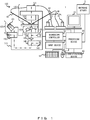
- Figure 1 is a diagram illustrating an example of a configuration of a microscope system 1 according to the present embodiment.
- Figure 2 is a diagram illustrating an example of a configuration of an inverted microscope 100.
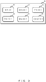
- Figure 3 is a diagram illustrating an example of a configuration of an operation unit of an input device 50.
- Figure 4 is a diagram illustrating an example of a functional configuration of a processing device 20.
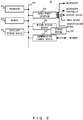
- Figure 5 is a diagram illustrating an example of a hardware configuration of the processing device 20.
- the microscope system 1 illustrated in Figure 1 is an inverted microscope system provided with a transillumination subsystem 120 used for micro-insemination, and is used by an embryologist who performs micro-insemination, for example.
- the microscope system 1 is provided with at least an eyepiece lens 101, objectives 102, a tube lens 103, an imaging unit 140, a processing device 20, and a projection device 153. Furthermore, in the microscope system 1, a modulation element for visualizing an unstained sample used in micro-insemination is provided in each of an illumination optical path and an observation optical path.
- the microscope system 1 uses the projection device 153 to project a projected image onto an image plane where an optical image of the sample is formed by one of the objectives 102 and the tube lens 103. With this arrangement, a user of the microscope system 1 sees an image in which the projected image is superimposed onto the optical image.
- the microscope system 1 is capable of providing various information that assists with micro-insemination superimposed onto the optical image to the user who observes a sample by peering into the eyepiece lens 101 to perform the micro-insemination work.
- the microscope system 1 is provided with an inverted microscope 100, a microscope controller 10, a processing device 20, a display device 30, a plurality of input devices (input device 40, input device 50, input device 60, input device 70), and an identification device 80. Furthermore, the microscope system 1 is connected to a database server 2 where various data is stored.
- the inverted microscope 100 is provided with a microscope body 110, in addition to a plurality of objectives 102, a stage 111, a transillumination subsystem 120, and an eyepiece tube 170, which are attached to the microscope body 110.
- the user is able to use the inverted microscope 100 to observe a sample according to the four microscopy methods of bright field (BF) observation, polarized (PO) observation, differential interference contrast (DIC) observation, and modulation contrast (MC) observation.
- BF bright field
- PO polarized
- DIC differential interference contrast
- MC modulation contrast
- modulation contrast observation is also referred to as relief contrast (RC) observation.
- the plurality of objectives 102 are mounted onto a revolving nosepiece 112. As illustrated in Figure 2 , the plurality of objectives 102 include an objective 102a used for BF observation, an objective 102b used for PO observation and DIC observation, and an objective 102c used for MC observation. Additionally, the objective 102c includes a modulator 104.
- the modulator 104 has three zones with different degrees of transmittance (for example, a zone with approximately 100% transmittance, a zone with approximately 5% transmittance, and a zone with approximately 0% transmittance).
- the plurality of objectives 102 may also include a plurality of objectives with different magnifications for each microscopy method.
- a 4x objective used for BF observation, 10x, 20x, and 40x objectives used for MC observation, a 20x objective used for PO observation, and a 60x objective used for DIC observation will be described as an example.
- the revolving nosepiece 112 is a switching device that switches the objective disposed on the optical path from among the plurality of objectives 102.
- the revolving nosepiece 112 switches the objective disposed on the optical path according to the microscopy method and the observation magnification.
- the objective disposed on the optical path by the revolving nosepiece 112 guides transmitted light that has transmitted through a sample to the eyepiece lens 101.
- a sample inserted into a container is placed on the stage 111.
- the container is a Petri dish and the sample includes reproductive cells, for example.
- the stage 111 moves in the optical axis direction of the objective 102 disposed on the optical path, and also in a direction orthogonal to the optical axis of the objective 102. Note that the stage 111 may be a manual stage or a motorized stage.
- the transillumination subsystem 120 illuminates the sample placed on the stage 111 from above the stage 111.
- the transillumination subsystem 120 includes a light source 121 and a universal condenser 122.
- the light source 121 may be a light-emitting diode (LED) light source or a halogen lamp light source, for example.
- the universal condenser 122 includes a polarizer 123 (first polarizing plate), a plurality of optical elements housed in a turret 124, and a condenser lens 128.
- the polarizer 123 is used in MC observation, PO observation, and DIC observation.
- a plurality of optical elements used by being switched depending on the microscopy method are housed in the turret 124.
- a DIC prism 125 is used in DIC observation.
- An aperture plate 126 is used in BF observation and PO observation.
- An optical element 127 is a combination of a slit plate 127a, which is a light-shielding plate having a slit formed therein, and a polarizing plate 127b (second polarizing plate) disposed to cover a portion of the slit.
- the optical element 127 is used in MC observation.
- the eyepiece lens 101 is included in the eyepiece tube 170.
- the tube lens 103 is disposed between the eyepiece lens 101 and the objective 102.
- the tube lens 103 forms an optical image of the sample on the basis of transmitted light in an image plane IP between the eyepiece lens 101 and the tube lens 103.
- a projected image described later is also formed in the image plane IP on the basis of light from the projection device 153. With this arrangement, the projected image is superimposed onto the optical image in the image plane IP.
- the user of the microscope system 1 uses the eyepiece lens 101 to observe a virtual image of the image in which the projected image is superimposed onto the optical image formed in the image plane IP.
- the microscope body 110 includes a laser-assisted hatching unit 130, an imaging unit 140, and a projection unit 150. Also, as illustrated in Figure 2 , the microscope body 110 includes an intermediate magnification change unit 160. Furthermore, the microscope body 110 includes a DIC prism 105 and an analyzer 106, which are detachable from the optical path.
- the laser-assisted hatching unit 130 is a laser unit disposed between the objective 102 and the tube lens 103.
- the laser-assisted hatching unit 130 shines laser light onto the sample by introducing laser light from between the objective 102 and the tube lens 103. More specifically, the laser-assisted hatching unit 130 shines laser light onto the zona pellucida surrounding an embryo that grows from a fertilized egg, for example.
- the laser-assisted hatching unit 130 includes a splitter 131, a scanner 133, a lens 134, and a laser 135.
- the splitter 131 is a dichroic mirror, for example.
- the scanner 133 is a galvano scanner, for example, and adjusts the irradiation position of the laser light in a direction orthogonal to the optical axis of the objective 102.
- the lens 134 converts the laser light into a beam of collimated light. With this arrangement, the laser light is condensed onto the sample by the objective 102.
- the imaging unit 140 is an imaging device that acquires digital image data of the sample on the basis of the transmitted light.
- the imaging unit 140 is disposed between the tube lens 103 and the eyepiece lens 101.
- the imaging unit 140 includes a splitter 141 and an imaging element 143.
- the splitter 141 is a half mirror, for example.
- the tube lens 103 forms an optical image of the sample on a light-receiving face of the imaging element 143.
- the imaging element 143 is for example a charge-coupled device (CCD) image sensor or a complementary metal-oxide-semiconductor (CMOS) image sensor that detects lights from the sample, and converts the detected light into an electrical signal by photoelectric conversion.
- the imaging unit 140 generates digital image data of the sample on the basis of the electrical signal obtained by the imaging element 143.
- CCD charge-coupled device
- CMOS complementary metal-oxide-semiconductor
- the microscope system 1 described later is used to observe samples such as sperm, and the fine features of sperm, such as the tail portion for example, are approximately ⁇ 0.5 ⁇ m.
- the pixel pitch is demanded to be ⁇ 0.5 ⁇ m or less when projected onto the object plane.
- the pitch of the pixel-projected image in the object plane calculated by dividing the pixel pitch by the total magnification (that is, the magnification of the objective ⁇ the magnification of the intermediate magnification change unit ⁇ the magnification of a camera adapter not illustrated) is demanded to be ⁇ 0.5 ⁇ m or less.
- the total magnification is 10x.
- the pitch of the pixel-projected image in the object plane is 0.345 ⁇ m, and even the tail portion of sperm is discernible. Note that when selecting the actual digital camera, further consideration should be given such that the region formed by the effective pixels has a size that fills the entire field of view.
- the projection unit 150 is disposed between the tube lens 103 and the eyepiece lens 101. As illustrated in Figure 2 , the projection unit 150 includes a splitter 151, a lens 152, and a projection device 153.
- the splitter 151 is a half mirror, for example.
- the projection device 153 projects a projected image on the basis of projected image data generated by the processing device 20.
- the lens 152 projects the projected image by condensing light from the projection device 153 onto the image plane of the tube lens 103, or in other words the same position as the image plane IP where the optical image is formed.
- the size of a single sperm from head to tail is roughly 60 ⁇ m, and the size of the head is approximately 3 ⁇ m across the short side. If such a sperm is projected onto the image plane IP in front of the eyepiece lens with the combination of a 20x objective used for MC observation and a 1x intermediate magnification change lens, the image of the sperm has a size of 1.2 mm ⁇ 0.06 mm. If projected image data containing such a sperm is created, the result is a rectangle with a minimum size of approximately 1.5 mm ⁇ 0.1 mm.
- a projection device 153 including a light-emitting element with a pitch of 0.05 mm or less (in the monochromatic case). This arrangement makes it possible to display a projected image in which the above 0.1 mm gap is perceivable.
- the projection device 153 projects a projected image onto a field of view that not only satisfies the field number ⁇ 22 of the eyepiece lens, but also an even larger field number of ⁇ 23 or greater.
- a projection device 153 having an effective light-emitting area of ⁇ 23 or greater is used.
- data about sperm in the periphery of the field of view entering the field of view from outside the eyepiece lens field of view is also included in the projected image data. Consequently, it is possible to recognize favorable sperm thoroughly from among all sperm inside the field of view, including the periphery of the eyepiece lens field of view.
- the effective pixel area of the imaging element 143 obviously also needs to have a size of ⁇ 23 or greater in the eyepiece lens part.
- the intermediate magnification change unit 160 is disposed between the objective 102 and the tube lens 103. As illustrated in Figure 2 , the intermediate magnification change unit 160 includes a plurality of lenses (lens 161, lens 162, lens 163), and by switching the lens disposed on the optical path from among these lenses, the magnification of the optical image formed in the image plane is changed. By using the intermediate magnification change unit 160, the magnification of the optical image can be changed without switching the objective 102 positioned close to the sample.
- the DIC prism 105 and the analyzer 106 are disposed between the objective 102 and the tube lens 103.
- the DIC prism 105 is used in DIC observation.
- the analyzer 106 is used in PO observation and DIC observation.
- the polarizer 123 and the optical element 127 are disposed on the illumination optical path as a first modulation element that modulates the illuminating light irradiating the sample, and the modulator 104 is disposed on the observation optical path as a second modulation element that modulates the transmitted light.
- the polarizer 123 is disposed on the illumination optical path as a first modulation element
- the analyzer 106 is disposed on the observation optical path as a second modulation element.
- the polarizer 123 and the DIC prism 125 are disposed on the illumination optical path as a first modulation element, and the analyzer 106 and the DIC prism 105 are disposed on the observation optical path as a second modulation element. With this arrangement, an unstained sample can be visualized.
- the microscope controller 10 is a device that controls the inverted microscope 100.
- the microscope controller 10 is connected to the processing device 20, the input device 50, and the inverted microscope 100, and controls the inverted microscope 100 according to commands from the processing device 20 or the input device 50.
- the display device 30 is a liquid crystal display, an organic EL (OLED) display, or a cathode ray tube (CRT) display, for example.
- OLED organic EL
- CRT cathode ray tube
- the input device 40 includes a handle 41 and a handle 42.
- the handle 41 and the handle 42 are operated to control the movements of micromanipulators not illustrated that move a pipette 43 and a pipette 44.
- the pipette 43 and the pipette 44 are used to manipulate the sample in micro-insemination work.
- the pipette 43 is a holding pipette, for example, and the pipette 44 is an injection pipette, for example.
- the input device 50 is a hand switch device for changing the settings of the inverted microscope 100. As illustrated in Figure 3 , the input device 50 includes six buttons (button 51 to button 56), for example, and by simply pressing these buttons, the user is able to quickly switch the settings of the inverted microscope 100.
- the settings of the inverted microscope 100 are switched to settings for BF observation at an observation magnification of 4x (hereinafter designated BF 4x observation).
- the settings of the inverted microscope 100 are switched to settings for MC observation at an observation magnification of 10x (hereinafter designated MC 10x observation).
- the settings of the inverted microscope 100 are switched to settings for MC observation at an observation magnification of 20x (hereinafter designated MC 20x observation).
- the settings of the inverted microscope 100 are switched to settings for MC observation at an observation magnification of 40x (hereinafter designated MC 40x observation).
- the settings of the inverted microscope 100 are switched to settings for PO observation at an observation magnification of 20x (hereinafter designated PO 20x observation).
- PO 20x observation an observation magnification of 20x
- DIC 60x observation an observation magnification of 60x
- the input device 60 is a keyboard.
- the input device 70 is a mouse.
- the input device 60 and the input device 70 are each connected to the processing device 20.
- the identification device 80 is a device that acquires identification information attached to a sample. Note that attaching identification information to a sample includes the case where the identification information is affixed to a container housing the sample, for example.
- the identification information is information that identifies the sample, and more specifically is information that specifies the patient who provided the sample.
- the identification device 80 is a barcode reader, an RFID(R) reader, or a QR Code(R) reader, for example.
- the processing device 20 is a device that controls the microscope system 1 overall. As illustrated in Figure 1 , the processing device 20 is connected to the inverted microscope 100, the microscope controller 10, the display device 30, the input device 60, the input device 70, and the identification device 80. Additionally, the processing device 20 is also connected to the database server 2.
- the processing device 20 generates projected image data corresponding to a projected image on the basis of at least digital image data acquired by the imaging unit 140.
- the projected image includes an assisting image that assists with micro-insemination.
- the processing device 20 controls the projection device 153 by outputting the projected image data to the projection device 153.
- the processing device 20 is provided with a camera control unit 21, an analysis unit 22, a projected image generation unit 23, and a projection control unit 24 mainly as components related to the control of the projection device 153.
- the camera control unit 21 acquires digital image data of the sample by controlling the imaging unit 140.
- the digital image data acquired by the camera control unit 21 is outputted to the analysis unit 22.
- the analysis unit 22 analyzes at least the digital image data acquired by the camera control unit 21, and outputs an analysis result to the projected image generation unit 23.
- the projected image generation unit 23 generates projected image data corresponding to the projected image including the assisting image that assists with micro-insemination on the basis of the analysis result generated by the analysis unit 22, and outputs the generated projected image data to the projection control unit 24.
- the analysis unit 22 may for example generate an analysis result that specifies candidate cells, that is, reproductive cells suitable for fertilization from among the reproductive cells included in the sample, on the basis of at least the digital image data.
- the projected image generation unit 23 may also generate projected image data corresponding to the projected image including an image (first assisting image) that specifies candidate cells as the assisting image.
- the projection control unit 24 controls the projection of the projected image onto the image plane by controlling the projection device 153. More specifically, the projection control unit 24 outputs the projected image data to the projection device 153, thereby causing the projection device 153 to project the projected image onto the image plane on the basis of the projected image data acquired from the projection control unit 24.
- the microscope system 1 configured as above is capable of superimposing the projected image including the assisting image that assists with micro-insemination onto the optical image. For this reason, the user is able to obtain information necessary for micro-insemination while observing the sample. Consequently, according to the microscope system 1, it is possible to assist with micro-insemination performed by the user.
- This configuration makes it possible to reduce inconsistencies in fertilization success rates among embryologists performing micro-insemination, and an improvement in fertilization success rates may be expected.
- the projected image is projected onto the image plane between the eyepiece lens 101 and the tube lens 103 and superimposed onto the optical image.
- the user is able to obtain various information that assists with micro-insemination while peering into the eyepiece lens 101, and movement of the line of sight, such as line of sight going back and forth between a monitor and the eyepiece lens 101, can be avoided compared to a case where the assisting image is displayed on a monitor or the like. Consequently, according to the microscope system 1, the user is able to obtain information necessary for micro-insemination from the projected image by simply observing the sample using the optical image, without taking his or her eyes away from the eyepiece lens 101.
- the microscope system 1 is capable of assisting with the work of micro-insemination with the assisting image and reducing the burden on the user for micro-insemination, without changing the user's workflow. Also, the work time of the user is shortened, and as a result, the amount of time that the sample is exposed to open air under the microscope is also shortened, thereby reducing the damage received by the sample.
- the processing device 20 included in the microscope system 1 may be a general-purpose device or a special-purpose device.
- the processing device 20 is not particularly limited in configuration, but may have a physical configuration like the one illustrated in Figure 5 , for example.
- the processing device 20 may be provided with a processor 20a, a memory 20b, an auxiliary storage device 20c, an input/output interface 20d, a medium driving device 20e, and a communication control device 20f, and these components may be interconnected by a bus 20g.
- the processor 20a is a processing circuit of any type, such as a central processing unit (CPU), for example.
- the processor 20a may execute programs stored in the memory 20b, the auxiliary storage device 20c, and a storage medium 20h to perform programmed processes, and thereby achieve the components (camera control unit 21, analysis unit 22, projected image generation unit 23, projection control unit 24) related to the control of the projection device 153 described above.
- the processor 20a may also be configured using a dedicated processor such as an application-specific integrated circuit (ASIC) or a field-programmable gate array (FPGA), and may also be configured using a graphics processing unit (GPU).
- ASIC application-specific integrated circuit
- FPGA field-programmable gate array
- the memory 20b is a working memory for the processor 20a.
- the memory 20b is a semiconductor memory of any type, such as random access memory (RAM), for example.
- the auxiliary storage device 20c is a non-volatile memory such as erasable programmable ROM (EPROM), a hard disk drive (HDD), or a solid-state drive (SSD).
- the input/output interface 20d exchanges information with external devices (inverted microscope 100, microscope controller 10, display device 30, input device 60, input device 70, identification device 80).
- the medium driving device 20e is capable of outputting data stored in the memory 20b and the auxiliary storage device 20c to the storage medium 20h, and is also capable of reading out information such as programs and data from the storage medium 20h.
- the storage medium 20h is a portable recording medium of any type.
- the storage medium 20h may be an SD card, Universal Serial Bus (USB) flash memory, a Compact Disc (CD), or a Digital Versatile Disc (DVD).
- the communication control device 20f inputs and outputs information with respect to a network.
- a device such as a network interface card (NIC), a Wi-Fi(R) module, a Bluetooth(R) module, or a BLE module may be adopted as the communication control device 20f.
- the bus 20g interconnects components such as the processor 20a, the memory 20b, and the auxiliary storage device 20c such that data can be exchanged among the components.
- Figure 6 is a flowchart illustrating an example of an ICSI procedure.
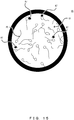
- Figure 7 is a diagram illustrating an example of a configuration of a drop formed as a sample 200 inside a Petri dish 210.
- Figure 8 is a flowchart illustrating an example of a sperm selection procedure.
- Figure 9 is a flowchart of an image projection process performed by the microscope system 1.
- Figure 10 is a diagram for explaining an image processing method performed by an analysis unit 22.
- Figure 11 is a diagram illustrating an example of an image seen from an eyepiece lens 101.
- an ICSI procedure that the user performs using the microscope system 1 will be described specifically with reference to Figures 6 to 11 .
- the user prepares a sample (step S1).
- the user creates a sample 200 including a plurality of drops inside a Petri dish 210 as illustrated in Figure 7 for example, and places the sample 200 onto the stage 111.
- a drop 201 is a cleaning drop used to clean the pipettes.
- Drops 202 are sperm suspension drops in which a sperm suspension is dropped into a PVP solution, for example.
- Drops 203 are egg manipulation drops in which eggs are placed in an m-HTF solution, for example. Note that the m-HTF solution is a Hepps-containing HTF solution to which 10% serum has been added. These drops are covered with mineral oil.
- the user sets up the microscope system 1 (step S2).
- the user presses the button 51 of the input device 50 to switch the settings of the microscope system 1 to BF 4x observation, for example.
- the user operates the input device 40 to adjust the positions of the pipette 43 and the pipette 44, and bring the pipette 43 and the pipette 44 into focus.
- the user moves the stage 111 to clean the pipette 43 and the pipette 44 with the drop 201 (cleaning drop).
- the user checks the growth state of the eggs (oocytes) inside the drops 203 (egg manipulation drops) (step S3).
- the user presses the button 53 of the input device 50 to switch the settings of the microscope system 1 to MC 20x observation, for example.
- the user observes the state of the eggs at MC 20x observation, and selects an egg.
- the user may also press the button 55 of the input device 50 to switch the settings of the microscope system 1 to PO 20x observation, for example.
- the user may assess the maturity of the eggs to further select an egg.
- step S4 When the selection of an egg is finished, the user selects a sperm according to the procedure illustrated in Figure 8 (step S4). First, the user presses the button 53 of the input device 50 to switch the settings of the microscope system 1 to MC 20x observation, for example. Next, the user moves the stage 111 to move the observation position to the drops 202 (sperm suspension drops), and bring the sperm into focus at MC 20x observation (step S11).
- step S12 the user selects sperm at MC 20x observation, and picks out favorable sperm suitable for fertilization (step S12). Whether a sperm is favorable or not is generally determined on the basis of the appearance and motility of the sperm, but definitive criteria do not exist. For this reason, the selection of sperm often depends on the experience and intuition of the embryologist acting as the user of the microscope system 1, and the judgment differs depending on the embryologist. This is a factor that leads to differences in fertilization success rates among embryologists.
- the microscope system 1 estimates that a sperm selected by an experienced embryologist with a high fertilization success rate are favorable sperm suitable for fertilization, and notifies the user of the microscope system 1 about the estimated sperm as candidate cells (candidate sperm).
- step S12 the microscope system 1 notifies the user of candidate cells by performing the image projection process illustrated in Figure 9 .
- the microscope system 1 projects an optical image O1 of the sample onto the image plane (step S21).
- the imaging unit 140 acquires digital image data of the sample (step S22).
- the digital image data acquired by the imaging unit 140 is outputted to the processing device 20, and the analysis unit 22 of the processing device 20 generates an analysis result that specifies candidate cells (candidate sperm) on the basis of the digital image data (step S23).
- the analysis algorithm that specifies the candidate cells is not particularly limited, but it is desirable to reproduce selection by an experienced embryologist with a high fertilization success rate. More specifically, it is desirable for the analysis unit 22 to analyze sperm on the basis of at least the appearance and motility of the sperm as a reproductive cell, and thereby reproduce selection by an experienced embryologist with a high fertilization success rate. Additionally, the digital image data used for the analysis may be still image data or moving image data.
- the analysis unit 22 may first process and combine the still image data of a still image M1 with an image indicating motility (an image of arrows), and thereby generate still image data of a still image M2.
- the image indicating motility is an image indicating a trail of movement by the sperm from the point in time going back a predetermined length of time to the current point, and may be generated on the basis of plural image data acquired within a corresponding period.
- the appearance and motility of the sperm may be analyzed on the basis of the still image data of the still image M2 obtained by combination with the image indicating motility, and an analysis result that specifies a candidate sperm may be generated.
- a rule-based algorithm that reproduces selection by an experienced embryologist may be adopted by the analysis unit 22.
- an algorithm (model) for estimating favorable sperm may be trained to select sperm like an experienced embryologist through machine learning, and the trained model may be adopted by the analysis unit 22.
- the machine learning may be traditional machine learning in which features necessary for estimation are given in advance by humans, or deep learning in which features are extracted by the machine itself.
- the projected image generation unit 23 of the processing device 20 When the analysis result is generated, the projected image generation unit 23 of the processing device 20 generates projected image data corresponding to a projected image P1 including an assisting image A1 that specifies each candidate cell based on the analysis result (step S24), and outputs the generated projected image data to the projection device 153. Thereafter, the projection device 153 projects the projected image P1 onto the image plane on the basis of the projected image data (step S25).
- an image V1 in which the projected image P1 including the assisting image(s) A1 is superimposed onto an optical image O1 is formed in the image plane, as illustrated in Figure 11 for example.
- Each assisting image A1 illustrated in Figure 11 is an image that surrounds an image of a candidate cell.
- the projected image P1 includes the assisting image A1 at a position that does not overlap with the image of each candidate cell when projected onto the image plane.
- step S12 the user can select sperm while paying attention to the candidate cells (candidate sperm) specified by the assisting images A1, and pick out favorable sperm. Consequently, the sperm selection work becomes easy, and the burden imposed by the selection work is reduced substantially.
- step S13 the user damages the tail of each favorable sperm at RC 20x observation to immobilize the favorable sperm.
- step S14 the user observes the appearance of the immobilized favorable sperm in further detail, and further selects favorable sperm (step S14).
- the microscope system 1 may estimate favorable sperm that an experienced embryologist with a high fertilization success rate would select, and notify the user of the microscope system 1 about the estimated favorable sperm as candidate cells (candidate sperm).
- step S14 differs from step S12 in that the analysis unit 22 analyzes the sperm on the basis of at least the appearance of the sperm.
- step S15 When the selection of favorable sperm at MC 40x observation is completed, the user further observes the heads of the favorable sperm in detail, and further selects favorable sperm according to the size of the blank existing in the head (step S15). At this point, the user presses the button 56 of the input device 50 to switch the settings of the microscope system 1 to DIC 60x observation, for example. Thereafter, the user picks out the favorable sperm having a small blank at DIC 60x observation. Note that step S15 may also be performed under MC 40x observation. In this case, the user picks out favorable sperm by recognizing a bright spot in the head as a blank.
- the user draws up the chosen favorable sperm into the pipette 44 acting as the injection pipette, moves the observation position to one of the drops 203 (egg manipulation drops) (step S16), and ends the series of steps in the sperm selection illustrated in Figure 8 .
- step S5 the user checks the position of the spindle to prepare for injection of favorable sperm (step S5).
- the user observes the egg chosen in step S3 existing inside one of the drops 203, and checks the position of the spindle of the egg.
- the user presses the button 55 of the input device 50 to switch the settings of the microscope system 1 to PO 20x observation, for example.
- the user reorients the spindle by manipulating the pipette 43 acting as the holding pipette, such that the spindle of the egg visualized at PO 20x observation is positioned in the 12 o'clock or the 6 o'clock direction. This is to avoid damaging the spindle with the pipette that is thrust into the egg from the 3 o'clock or 9 o'clock direction in step S6 described later.
- step S6 the user injects the sperm into the egg (step S6), and ends ICSI.
- the favorable sperm is injected into the egg from the pipette 44.
- the user returns the egg containing the injected sperm to an incubator for cultivation. Additionally, the user may also operate the processing device 20 using the input device 60 and the input device 70 to save information obtained by ICSI in the database server 2. For example, patient information about the sperm and the egg (such as clinical data about the mother and examination results regarding the semen containing the sperm), and data about the culture fluid of the sperm and the egg (such as the type, concentration, and pH, for example) may be associated with information such as image data of the egg containing the injected sperm, image data of the favorable sperm picked out, and the ICSI work time, and saved in the database server 2.
- patient information about the sperm and the egg such as clinical data about the mother and examination results regarding the semen containing the sperm
- data about the culture fluid of the sperm and the egg such as the type, concentration, and pH, for example
- This information may also be used in the analysis by the analysis unit 22 used in steps S12 and S14 of Figure 8 .
- the processing device 20 may generate projected image data corresponding to a projected image including an assisting image on the basis of digital image data as well as other data saved in the database server 2. In this way, by synthesizing a variety of information not solely limited to image data to estimate favorable sperm, the achievement of even higher fertilization success rates may be expected.
- a projected image including an assisting image that specifies candidate sperm is projected onto the image plane.
- the size of sperm is approximately 60 ⁇ m, and an objective with a magnification of at least 20x is used to distinguish favorable sperm. Because the field number of an inverted microscope is generally approximately 22, the actual field of view is approximately ⁇ 1 mm. It is extremely difficult to perform the work of selecting freely-moving sperm inside a region with an actual field of view of ⁇ 1 mm.
- the sperm selection work requires the user to observe the appearance of relatively fast-moving sperm quickly and judge whether the sperm is favorable or not.
- superimposing an assisting image that specifies a candidate sperm estimated as a favorable sperm onto an optical image greatly contributes to reducing the burden of the sperm selection work.
- improved fertilization success rates can be achieved while at the same time also reducing inconsistencies in fertilization success rates among embryologists. Consequently, according to the microscope system 1, it is possible to assist with sperm selection by the user effectively.
- Figures 12 to 15 are diagrams illustrating other examples of images seen from the eyepiece lens 101.
- the microscope system 1 may superimpose any of the projected images P2 to P5 illustrated in Figures 12 to 15 instead of the projected image P1 illustrated in Figure 11 onto the optical image O1.
- An image V2 illustrated in Figure 12 is obtained by superimposing a projected image P2 onto the optical image O1.
- Figure 11 illustrates an example in which the projected image P1 includes the assisting image A1 having a shape that surrounds each image of a candidate sperm, but the projected image may also include other images.
- the projected image P2 includes an assisting image A2 indicating the trail of movement of each candidate sperm in addition to the assisting image A1 that specifies each candidate sperm.
- the assisting image A2 expresses the motility of each candidate sperm with the trail of movement.
- An image V3 illustrated in Figure 13 is obtained by superimposing a projected image P3 onto the optical image O1.
- Figure 11 illustrates an example of specifying candidate sperm with a single type of image (assisting image A1), but candidate sperm may also be specified with multiple types of images.
- the projected image P3 includes two types of images (assisting image A1 and assisting image A3) that specify candidate sperm.
- the assisting image A3 is an image that specifies candidate sperm having a lower degree of recommendation compared to the assisting image A1, and the color of the assisting image A3 (light blue, for example) is different from the color of the assisting image A1 (dark blue, for example).
- the assisting image A1 and the assisting image A3 are respectively colored according to the degree of recommendation of the candidate sperm specified by the assisting image.
- the degree of recommendation of sperm may be absolute or relative. In actuality, some patients may only have suboptimal sperm overall, and in such cases, a relatively healthy sperm is selected from among the limited choices. In this case, even if the degree of recommendation is absolute, if the system is set to project multiple images indicating multiple types of degrees of recommendation, then at least an image indicating a relatively low degree of recommendation will be projected.
- the assisting image A3 with a light blue color will be projected even if the assisting image A1 with a dark blue color is not projected. Consequently, the possibility where no assisting images are projected at all can be greatly reduced.
- the images are not limited to indicating high degrees of recommendation, and images indicating particularly low degrees of recommendation may also be projected.
- An image V4 illustrated in Figure 14 is obtained by superimposing a projected image P4 onto the optical image O1.
- Figure 13 illustrates an example of an assisting image colored according to the degree of recommendation of candidate sperm, but it is sufficient for an assisting image to have a different appearance depending on the degree of recommendation of the candidate sperm specified by the assisting image.
- the projected image P4 includes four types of images (assisting image A1, assisting image A4, assisting image A5, and assisting image A6) that specify candidate sperm. These assisting images have different line styles or shapes from each other, and express degrees of recommendation of candidate sperm according to the differences in the line styles or shapes.
- An image V5 illustrated in Figure 15 is obtained by superimposing a projected image P5 onto the optical image O1.
- Figure 11 illustrates an example in which the projected image P1 includes the assisting image A1 having a shape that surrounds each image of a candidate sperm, but it is sufficient for the projected image to include an image that specifies a candidate sperm.
- the projected image P5 illustrated in Figure 15 includes an assisting image A7 having a shape that points out an image of a candidate sperm.
- the user can easily grasp the candidate sperm, and the burden of the sperm selection work can be greatly reduced.
- Figure 16 is a diagram illustrating a configuration of a neural network.
- Figure 17 is a flowchart illustrating an example of a training procedure.
- Figure 18 is a diagram for explaining a method of applying labels to teaching images.
- the analysis unit 22 may adopt a model trained by machine learning or a neural network trained by deep learning, for example. In other words, the analysis unit 22 may use a trained neural network to at least analyze digital image data.
- a procedure for training the neural network NN illustrated in Figure 16 to recognize favorable sperm will be described with reference to Figures 16 to 18 .
- the microscope system 1 records the work of selecting sperm performed under MC 20x observation as a moving image or a still image (step S31). At this point, during the sperm selection work, the imaging unit 140 acquires image data, and the processing device 20 saves the image data.
- the microscope system 1 extracts images of sperm portions from the recorded image, and arranges the extracted images for display (step S32).
- the processing device 20 reads out the moving image data or still image data saved in step S31, extracts images of sperm portions from the moving image or still image as teaching images, and arranges the teaching images for display on the display device 30.
- the teaching images arranged for display are evaluated by an experienced embryologist with a high fertilization success rate.
- the microscope system 1 labels the teaching images on the basis of the evaluations by an experienced embryologist (step S33).
- the evaluation results (labels) provided by the experienced embryologist are saved in association with the teaching images.
- teaching data data combining the teaching images and the labels will be referred to as teaching data.
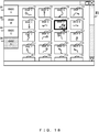
- teaching images (T1, T10, T14, ...) that are clicked while a button B1 is selected in a window W1 are saved in association with a Grade A label.
- teaching images (T2, T3, T6, T8, T9, T11, T15, ...) that are clicked while a button B2 is selected are saved in association with a Grade B label.
- teaching images (T4, T5, T13, T16, ...) that are clicked while a button B3 is selected are saved in association with a Grade C label.
- teaching images (T7, T12, ...) that are clicked while a button B4 is selected are saved in association with a Grade D label.
- Grades A, B, C, and D indicate successively lower degrees of recommendation in the above order.
- the microscope system 1 uses a large amount of created teaching data to train a neural network (step S34).
- the microscope system 1 performs processes similar to steps S31 to S33 for selection work under MC 40x observation to train the neural network (step S35). With this arrangement, the microscope system 1 obtains a trained neural network.
- the trained neural network of the microscope system 1 is a neural network that has been trained using image data corresponding to images of sperm labeled as suitable or unsuitable for fertilization as the teaching data.
- the microscope system 1 verifies the trained neural network (step S36). At this point, the microscope system 1 verifies whether or not the neural network recognizes favorable sperm appropriately with respect to different sperm than the training stage, for example. If the verification result confirms that favorable sperm is recognized appropriately, the trained neural network obtained in step S35 is adopted by the analysis unit 22.
- neural networks may be trained in units of hospitals, or further trained in units of hospitals, and a different model for each hospital may be adopted in the analysis unit 22. This arrangement makes it possible to easily accommodate favorable sperm selection conforming to the guidelines of each hospital.
- Figure 17 illustrates an example of using the microscope system 1 to generate the teaching data and train the neural network
- the generation of the teaching data and the training of the neural network may also be performed by a different system from the microscope system 1, and a trained neural network that has been constructed on another system may be applied to the microscope system 1.
- Figure 19 is a diagram for explaining a method of creating teaching data.
- Figure 18 illustrates an example in which the microscope system 1 labels data by having an embryologist evaluate teaching images displayed on the display device 30, but an embryologist may also label images seen using the eyepiece lens 101.
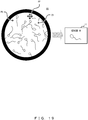
- the processing device 20 when an experienced embryologist is observing sperm using the eyepiece lens 101 under MC 20x observation, the processing device 20 generates pointer image data corresponding to a pointer image PP that points out a position corresponding to a mouse movement operation (first input operation) performed by the embryologist, and the projection device 153 projects the pointer image PP onto the image plane on the basis of the pointer image data, as illustrated in Figure 19 .
- An image V6 illustrated in Figure 19 is obtained by superimposing a projected image P6 onto the optical image O1.
- the projected image P6 includes the pointer image PP that points out the position corresponding to a mouse movement operation.
- the processing device 20 specifies the sperm selected by the embryologist on the basis of the position of the pointer image PP when the mouse click operation is detected. Subsequently, an image T1 of the specified sperm is recorded as a teaching image.
- the image T1 may also be labeled according to the content of the second input operation. For example, the image may be labeled as Grade A if the mouse click operation is a left click, as Grade B if the mouse click operation is a left double-click, or as Grade C if the mouse click operation is a right click.
- a teaching image can be acquired and labeled at the same time to generate teaching data.
- the image quality of images displayed on the display device 30 is degraded compared to the image quality of images observed using the eyepiece lens 101, and therefore it is difficult to distinguish subtle individual differences between sperm from images displayed on the display device 30.
- sperm can be selected and teaching data can be created while recognizing subtle individual differences between sperm under the same environment as the ICSI work. Consequently, the knowledge of an experienced embryologist with a high fertilization success rate can be converted into teaching data more correctly.
- Figures 20 and 21 are diagrams illustrating still other examples of images seen from the eyepiece lens 101.
- the above illustrates an example in which the projected image includes an assisting image that specifies candidate sperm, but in addition to the assisting image that specifies candidate sperm, the projected image may also include another assisting image that assists with micro-insemination.
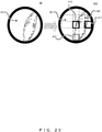
- An image V7 illustrated in Figure 20 is obtained by superimposing a projected image P7 onto the optical image O1.
- the projected image P7 includes an assisting image A9 indicating information about the patient (one example of a seventh assisting image) in addition to the assisting image A1 that specifies each candidate sperm.
- the identification device 80 acquires identification information attached to the sample.
- the processing device 20 acquires information about the patient providing the sample, on the basis of the identification information acquired by the identification device 80. Specifically, for example, the processing device 20 acquires information about the patient providing the sample by extracting information about the patient corresponding to the identification information from the database server 2.
- the information about the patient includes information such as the name of the patient and an ID, for example.
- the processing device 20 generates projected image data corresponding to the projected image P7 including the assisting image A1 and the assisting image A9 on the basis of at least the digital image data acquired by the imaging unit 140 and the information about the patient.
- the projection device 153 projects the projected image P7 onto the image plane on the basis of the projected image data, thereby causing the image V7 to be formed in the image plane.
- the assisting image A9 indicating information about the patient onto the image plane, the user can perform ICSI while continually confirming the patient acting as the sperm donor.
- An image V8 illustrated in Figure 21 is obtained by superimposing a projected image P8 onto the optical image O1.
- the projected image P8 includes an assisting image A10 indicating the elapsed time since the processing device 20 detected a predetermined operation (one example of an eighth assisting image) in addition to the assisting image A1 that specifies each candidate sperm.
- the predetermined operation is an operation of placing a sample on the stage 111, for example.
- the processing device 20 acquires the elapsed time since a sample was placed on the stage 111.
- the processing device 20 generates projected image data corresponding to the projected image P8 including the assisting image A1 and the assisting image A10 on the basis of at least the digital image data acquired by the imaging unit 140 and the elapsed time.
- the projection device 153 projects the projected image P8 onto the image plane on the basis of the projected image data, thereby causing the image V8 to be formed in the image plane.
- the user can perform ICSI while confirming the elapsed time.
- Figure 22 is a flowchart illustrating another example of a sperm selection procedure.
- Figure 23 is a diagram illustrating yet another example of an image seen from the eyepiece lens 101.
- the configuration of the microscope system according to the present embodiment is similar to the configuration of the microscope system 1, and therefore components of the microscope system according to the present embodiment will be referenced by the same signs as the components of the microscope system 1.
- the present embodiment differs from the first embodiment in that the sperm selection work in ICSI is performed according to the procedure illustrated in Figure 22 instead of the procedure illustrated in Figure 8 .
- the user presses the button 52 of the input device 50 to switch the settings of the microscope system to MC 10x observation, for example.
- the user moves the stage 111 to move the observation position to the drops 202 (sperm suspension drops), and bring the drops 202 into focus at MC 10x observation (step S41).
- the user observes the drops 202 at MC 10x observation, and moves the stage 111 to move the observation position to a region where favorable sperm are expected to exist.
- the microscope system estimates a region where favorable sperm are expected to exist, and assists with the work by the user by notifying the user about the estimated region as a candidate region.
- An image V9 illustrated in Figure 23 is an optical image O2 at MC 10x observation. As illustrated by the image V9, at MC 10x observation, the detailed appearance of the sperm inside one of the drops 202 cannot be confirmed, but the existence of sperm can be confirmed. Accordingly, in step S42, first, the analysis unit 22 divides the sample into a plurality of regions on the basis of the digital image data, treats the region in which the amount of movement by sperm is greater than the amount of movement by sperm inside other regions as a candidate region, and generates an analysis result (second analysis result) that specifies the candidate region.
- the projected image generation unit 23 generates projected image data corresponding to a projected image including an assisting image (second assisting image) that specifies the candidate region.
- the projection device 153 notifies the user of the candidate region by projecting the projected image onto the image plane on the basis of the projected image data.
- An image V10 illustrated in Figure 23 is obtained by superimposing a projected image P10 onto the optical image O2.
- the projected image P10 includes an assisting image A11 that specifies each candidate region.
- the projected image P10 also includes an assisting image A12 that specifies a region where the amount of movement by sperm is small.
- step S42 the user can specify a region where favorable sperm are expected to exist by referencing the assisting image A11, and move the observation position to the specified region. Consequently, it is possible to avoid wasting time due to moving the observation position to regions where favorable sperm do not exist.
- step S43 to step S47 is similar to the procedure from step S12 to step S16 illustrated in Figure 8 .
- an assisting image that specifies candidate sperm estimated to be favorable sperm is likewise superimposed onto an optical image, thereby making it possible to reduce the burden of the sperm selection work and assist with micro-insemination, similarly to the microscope system 1. Furthermore, according to the microscope system according to the present embodiment, it is possible to avoid moving the observation position to regions where favorable sperm do not exist. Consequently, it is possible to avoid a situation of repeatedly moving the stage 111 to search for favorable sperm.
- the present embodiment illustrates an example of capturing an assisting image that specifies one or more candidate regions at MC 10x observation and projecting an assisting image that specifies candidate sperm at MC 20x observation
- these magnifications are merely an example. It is sufficient if the assisting image that specifies one or more candidate regions is captured at a magnification lower than a predetermined magnification factor, and the assisting image that specifies the candidate sperm at a magnification equal to or higher than the predetermined magnification.
- the analysis unit 22 may generate an analysis result that specifies candidate cells, and on the basis of the analysis result, the projected image generation unit 23 may generate projected image data corresponding to a projected image including an assisting image that specifies the candidate cells.
- the analysis unit 22 may generate an analysis result that specifies a candidate region, and on the basis of the analysis result, the projected image generation unit 23 may generate the projected image data corresponding to a projected image including an assisting image that specifies the candidate region.
- Figure 24 is a diagram illustrating yet another example of an image seen from the eyepiece lens 101.
- the configuration of the microscope system according to the present embodiment is similar to the configuration of the microscope system 1, and therefore components of the microscope system according to the present embodiment will be referenced by the same signs as the components of the microscope system 1.
- testicular sperm extraction TSE
- An image V11 illustrated in Figure 24 is obtained by superimposing a projected image P11 onto an optical image O3.
- the optical image O3 is an image of seminiferous tubules inside the testicles, extracted by making an incision in the scrotum.
- the optical image O3 includes images of various tissues, including red blood cells and white blood cells.
- the projected image P11 includes an assisting image (fourth assisting image) that specifies reproductive cells, namely sperm.
- the analysis unit 22 generates an analysis result that specifies sperm included in the sample on the basis of at least digital image data. Also, on the basis of the analysis result generated by the analysis unit 22, the projected image generation unit 23 generates projected image data including an assisting image that specifies each sperm as an assisting image. Furthermore, the projection device 153 projects the projected image onto the image plane on the basis of the projected image data. With this arrangement, as illustrated in Figure 24 , the projected image P11 including the assisting image A13 is superimposed onto the optical image O3.
- sperm mixed in among a variety of tissues can be specified easily in TESE. Consequently, it is possible to greatly reduce the burden of the sperm searching work and assist with micro-insemination, similarly to the microscope system 1.
- Figure 25 is a flowchart illustrating an example of a procedure for preimplantation diagnosis.
- Figure 26 is a diagram illustrating yet another example of an image seen from the eyepiece lens 101.
- the configuration of the microscope system according to the present embodiment is similar to the configuration of the microscope system 1, and therefore components of the microscope system according to the present embodiment will be referenced by the same signs as the components of the microscope system 1.
- the microscope system according to the present embodiment differs from the microscope system 1 according to the first embodiment by being used for laser-assisted hatching for assisting with the implantation of an embryo (blastocyst) developed from a fertilized egg and also for the extraction of trophectoderm cells for preimplantation diagnosis.
- the sample includes an embryo developed from a fertilized egg and the zona pellucida surrounding the embryo.
- the user presses the button 53 or the button 54 of the input device 50 to switch the settings of the microscope system to MC 20x observation or MC 40x observation, for example. Additionally, the user moves the stage 111 to bring the zona pellucida surrounding the embryo into focus (step S51).
- step S52 the user observes the zona pellucida, and decides a position for laser irradiation by the laser-assisted hatching unit 130 (step S52).
- the zona pellucida has a qualitative abnormality, such as being thick or hard, the embryo will be unable to pierce the zona pellucida and become implanted in the endometrium.
- laser-assisted hatching removes the zona pellucida to assist with implantation.
- step S52 it is necessary to decide the position to be irradiated with laser light appropriately to remove the zona pellucida without injuring the embryo.
- the microscope system calculates an appropriate irradiation position by image analysis and notifies the user.
- the analysis unit 22 generates an analysis result that specifies a candidate spot suitable for irradiation with laser light in the zona pellucida, on the basis of at least digital image data acquired by the imaging unit 140.
- the projected image generation unit 23 generates projected image data corresponding to a projected image including an assisting image (fifth assisting image) that specifies the candidate spot as an assisting image that generates projected image data.
- the projection device 153 projects the projected image onto the image plane on the basis of the projected image data generated by the projected image generation unit 23, and superimposes the projected image onto an optical image of the sample.
- An image V12 illustrated in Figure 26 is obtained by superimposing a projected image P12 onto an optical image O4.
- the optical image O4 includes an image of an embryo (inner cell mass 041, blastocoel O42, and trophectoderm O43) and an image of a zona pellucida O44 surrounding the embryo.
- the projected image P12 includes an assisting image A14 that specifies a candidate spot suitable for irradiation with laser light.
- step S52 the user can refer to the position of the assisting image A14 to decide and set the position for laser irradiation in the laser-assisted hatching unit 130. Consequently, an appropriate position for laser irradiation can be set easily.
- An image V13 illustrated in Figure 26 is an optical image O5 of the sample after irradiation with laser light, and illustrates a state after an aperture AP has been formed in the zona pellucida O44 by irradiation with laser light.
- the microscope system specifies the position of the trophectoderm O43 by image analysis and notifies the user.
- the analysis unit 22 generates an analysis result that specifies the trophectoderm O43 inside the embryo on the basis of at least digital image data acquired by the imaging unit 140.
- the projected image generation unit 23 generates projected image data corresponding to a projected image including an assisting image (sixth assisting image) that specifies the trophectoderm as an assisting image.
- the projection device 153 projects the projected image onto the image plane on the basis of the projected image data generated by the projected image generation unit 23, and superimposes the projected image onto an optical image of the sample.
- An image V14 illustrated in Figure 26 is obtained by superimposing a projected image P14 onto an optical image O5.
- the projected image P14 includes an assisting image A15 that specifies the trophectoderm O43.
- step S54 the user can easily confirm the position of the trophectoderm with the assisting image A15.
- step S55 the user inserts a pipette into the aperture AP and extracts the trophectoderm O43 (step S55). At this point, negative pressure is applied to the inserted pipette to suction the trophectoderm O43 at the position confirmed in step S54.
- the trophectoderm is highly viscous, the trophectoderm protrudes out from the embryo after pulling the pipette out from the aperture AP. For this reason, the user uses the laser-assisted hatching unit 130 again to sever the trophectoderm protruding out by irradiating the space between the pipette and the embryo with laser light (step S56).
- step S57 the user inspects the extracted trophectoderm inside the pipette. At this point, several cells of the extracted trophectoderm are used to make a preimplantation diagnosis.
- the analysis unit 22 may also adopt a rule-based algorithm or a trained model constructed by machine learning.
- Figure 12 illustrates an example of projecting the assisting image A1 that specifies each candidate sperm together with the assisting image A2 that indicates the trail of movement by each candidate sperm, but it is also possible to superimpose only an assisting image (third assisting image) that indicates the trail of movement by each candidate sperm onto the optical image.
- the analysis unit 22 may specify a trail of movement by a reproductive cell included in the sample on the basis of digital image data, and on the basis of the analysis result, the projected image generation unit 23 may generate projected image data corresponding to a projected image including an assisting image that indicates the trail of movement by the reproductive cell as an assisting image.
- an assisting image that indicates a trail of movement by sperm other than the candidate sperm may also be projected.
- the embodiments described above illustrate an example of a microscope system that observes a sample according to the four microscopy methods of bright field (BF) observation, polarized (PO) observation, differential interference contrast (DIC) observation, and modulation contrast (MC) observation, but the sample may also be observed according to another microscopy method such as phase-contrast (PC) observation in addition to the above.
- BF bright field
- PO polarized
- DIC differential interference contrast
- MC modulation contrast
- PC phase-contrast
- a phase-contrast objective is included.
- Figure 27 is a diagram illustrating an example of a configuration of an inverted microscope 300.
- the microscope system 1 may include the inverted microscope 300 instead of the inverted microscope 100.
- the inverted microscope 300 differs from the inverted microscope 100 in that an imaging unit 144 is included instead of the imaging unit 140, and the tube lens 103 is positioned between the imaging unit 144 and the eyepiece lens 101.
- the imaging unit 144 includes a lens 145 for condensing light incident without passing through the tube lens 103 onto the imaging element 143.
- the microscope system 1 is capable of obtaining effects similar to the case of including the inverted microscope 100.
- FIG 28 is a diagram illustrating an example of a configuration of an inverted microscope 400.
- the microscope system 1 may include the inverted microscope 400 instead of the inverted microscope 100.
- the inverted microscope 400 differs from the inverted microscope 100 in that the imaging unit 144 is included instead of the imaging unit 140, a projection unit 154 is included instead of the projection unit 150, and the tube lens 103 is positioned between the projection unit 154 and the eyepiece lens 101.
- the imaging unit 144 includes a lens 145 for condensing light incident without passing through the tube lens 103 onto the imaging element 143.
- the projection unit 154 includes a lens 155 having a different focal length than the lens 152, so as to condense light onto the image plane IP through the tube lens 103.
- the microscope system 1 is capable of obtaining effects similar to the case of including the inverted microscope 100.
Landscapes
- Engineering & Computer Science (AREA)
- Physics & Mathematics (AREA)
- General Physics & Mathematics (AREA)
- Optics & Photonics (AREA)
- Chemical & Material Sciences (AREA)
- Analytical Chemistry (AREA)
- Theoretical Computer Science (AREA)
- Multimedia (AREA)
- Health & Medical Sciences (AREA)
- General Health & Medical Sciences (AREA)
- Computer Vision & Pattern Recognition (AREA)
- Medical Informatics (AREA)
- Quality & Reliability (AREA)
- Nuclear Medicine, Radiotherapy & Molecular Imaging (AREA)
- Radiology & Medical Imaging (AREA)
- Life Sciences & Earth Sciences (AREA)
- Molecular Biology (AREA)
- Biomedical Technology (AREA)
- Evolutionary Computation (AREA)
- Computing Systems (AREA)
- Software Systems (AREA)
- Databases & Information Systems (AREA)
- Artificial Intelligence (AREA)
- Microscoopes, Condenser (AREA)
- Image Input (AREA)
- Image Analysis (AREA)
- Apparatus Associated With Microorganisms And Enzymes (AREA)
Applications Claiming Priority (2)
| Application Number | Priority Date | Filing Date | Title |
|---|---|---|---|
| JP2018247359 | 2018-12-28 | ||
| PCT/JP2019/051101 WO2020138279A1 (fr) | 2018-12-28 | 2019-12-26 | Système de microscope |
Publications (3)
| Publication Number | Publication Date |
|---|---|
| EP3904937A1 true EP3904937A1 (fr) | 2021-11-03 |
| EP3904937A4 EP3904937A4 (fr) | 2022-09-21 |
| EP3904937B1 EP3904937B1 (fr) | 2025-04-09 |
Family
ID=71128709
Family Applications (1)
| Application Number | Title | Priority Date | Filing Date |
|---|---|---|---|
| EP19906490.8A Active EP3904937B1 (fr) | 2018-12-28 | 2019-12-26 | Système de microscope |
Country Status (5)
| Country | Link |
|---|---|
| US (1) | US11861921B2 (fr) |
| EP (1) | EP3904937B1 (fr) |
| JP (1) | JP7214753B2 (fr) |
| CN (1) | CN113260894B (fr) |
| WO (1) | WO2020138279A1 (fr) |
Cited By (2)
| Publication number | Priority date | Publication date | Assignee | Title |
|---|---|---|---|---|
| EP4209820A1 (fr) * | 2021-12-27 | 2023-07-12 | Evident Corporation | Système de microscope et procédé de support de tri |
| EP4130843A4 (fr) * | 2020-03-31 | 2024-05-01 | Evident Corporation | Système de microscope, unité de projection et procédé d'aide au triage de sperme |
Families Citing this family (17)
| Publication number | Priority date | Publication date | Assignee | Title |
|---|---|---|---|---|
| CN112714887B (zh) | 2018-09-28 | 2024-02-23 | 仪景通株式会社 | 显微镜系统、投影单元以及图像投影方法 |
| CN112703440B (zh) | 2018-09-28 | 2022-12-23 | 仪景通株式会社 | 显微镜系统 |
| CN112714888B (zh) | 2018-09-28 | 2023-02-17 | 仪景通株式会社 | 显微镜系统、投影单元以及图像投影方法 |
| EP3988987A4 (fr) * | 2018-09-28 | 2023-09-20 | Evident Corporation | Système de microscope, unité de projection et procédé de projection d'image |
| CN115552309A (zh) * | 2020-03-31 | 2022-12-30 | 仪景通株式会社 | 显微镜系统、投影单元以及检卵辅助方法 |
| JP7568212B2 (ja) * | 2020-08-27 | 2024-10-16 | リプロバイオ株式会社 | 精子運動性能評価システム及び精子運動性能評価方法 |
| US20230326165A1 (en) * | 2020-09-11 | 2023-10-12 | The Brigham And Women's Hospital, Inc. | Determining locations in reproductive cellular structures |
| US20220156922A1 (en) * | 2020-11-17 | 2022-05-19 | Alejandro Chávez Badiola | System for real-time automatic quantitative evaluation, assessment and/or ranking of individual sperm, aimed for intracytoplasmic sperm injection (icsi), and other fertilization procedures, allowing the selection of a single sperm |
| JP7755381B2 (ja) * | 2021-01-08 | 2025-10-16 | 株式会社エビデント | 顕微鏡 |
| US20220293219A1 (en) | 2021-03-09 | 2022-09-15 | Thread Robotics Inc. | System and method for dfi-based gamete selection |
| US11694344B2 (en) * | 2021-11-05 | 2023-07-04 | Thread Robotics Inc. | System and method for automated cell positioning |
| CN114518362A (zh) * | 2022-02-24 | 2022-05-20 | 上海北昂医药科技股份有限公司 | 精子质量分析装置、系统、方法及可读存储介质 |
| JP7851755B2 (ja) * | 2022-03-08 | 2026-04-27 | 株式会社エビデント | 接眼鏡筒 |
| EP4731105A1 (fr) * | 2023-06-26 | 2026-04-29 | Conceivable Life Sciences, Inc. | Fécondation in vitro automatisée intelligente et arrière-plan de plateforme d'injection de sperme intracytoplasmique |
| JP7580169B1 (ja) * | 2024-09-09 | 2024-11-11 | 株式会社アークス | 精子選別補助装置、精子選別補助システム、及び精子選別補助プログラム |
| CN118879485A (zh) * | 2024-09-27 | 2024-11-01 | 季华实验室 | Icsi辅助操作仪及其控制方法 |
| JP7751345B1 (ja) * | 2025-04-24 | 2025-10-08 | 株式会社アークス | 精子選別補助装置、投影装置、及び顕微鏡システム |
Family Cites Families (28)
| Publication number | Priority date | Publication date | Assignee | Title |
|---|---|---|---|---|
| JPH0829694A (ja) * | 1994-07-20 | 1996-02-02 | Nikon Corp | 画像処理装置付き顕微鏡 |
| WO2010021392A1 (fr) * | 2008-08-21 | 2010-02-25 | 独立行政法人理化学研究所 | Procédé d’observation par fluorescence in vitro pour embryon mammalien, et procédé de selection d’embryon mammalien réduit en termes de risque d’échec d’implantation ou d’avortement |
| EP2447752A4 (fr) | 2009-05-08 | 2018-07-04 | Nikon Corporation | Dispositif de commande de mise au point, et dispositif d'incubation et d'observation |
| JP2011004638A (ja) | 2009-06-24 | 2011-01-13 | Nikon Corp | 受精卵観察の画像処理方法、画像処理プログラム及び画像処理装置 |
| JP5581752B2 (ja) * | 2010-03-16 | 2014-09-03 | 株式会社ニコン | オートフォーカス光学装置、顕微鏡 |
| CA2812776C (fr) | 2010-09-27 | 2022-05-17 | Auxogyn, Inc. | Appareil, procede et systeme pour l'imagerie automatisee et l'evaluation d'embryons, d'ovocytes et de cellules souches |
| JP5532459B2 (ja) * | 2011-01-12 | 2014-06-25 | 株式会社ニコン | 顕微鏡システム |
| WO2012150689A1 (fr) | 2011-05-02 | 2012-11-08 | オリンパス株式会社 | Microscope et procédé de micro-insémination utilisant un microscope |
| US8928973B2 (en) * | 2011-12-16 | 2015-01-06 | Taiwan Semiconductor Manufacturing Company, Ltd. | Microscope apparatus for phase image acquisition |
| JP6076042B2 (ja) | 2012-11-01 | 2017-02-08 | オリンパス株式会社 | 顕微鏡および制御方法 |
| US9177192B2 (en) | 2013-02-28 | 2015-11-03 | Progyny, Inc. | Apparatus, method, and system for image-based human embryo cell classification |
| JP6192335B2 (ja) | 2013-03-29 | 2017-09-06 | オリンパス株式会社 | 顕微鏡 |
| JP6150586B2 (ja) | 2013-03-29 | 2017-06-21 | オリンパス株式会社 | 顕微鏡 |
| EP2993509B1 (fr) * | 2013-04-30 | 2019-06-26 | Olympus Corporation | Dispositif d'observation d'échantillon et procédé d'observation d'échantillon |
| CN103389369A (zh) | 2013-07-31 | 2013-11-13 | 中国人民解放军军事医学科学院基础医学研究所 | 一种快速简便判定精液粘稠度的方法 |
| WO2015077333A1 (fr) * | 2013-11-20 | 2015-05-28 | Brigham And Women's Hospital , Inc. | Système et procédé de tri de spermatozoïdes |
| WO2016001754A2 (fr) * | 2014-07-01 | 2016-01-07 | Institut National De La Santé Et De La Recherche Médicale (Inserm) | Procédés de reconstruction tridimensionnelle et de détermination de la qualité d'un embryon |
| CN107615066B (zh) * | 2015-05-07 | 2020-06-30 | 技术创新动力基金(以色列)有限合伙公司 | 用于包括精子的生物细胞和生物有机体的干涉系统和方法 |
| JP6696152B2 (ja) * | 2015-11-11 | 2020-05-20 | ソニー株式会社 | 情報処理装置、情報処理方法、プログラム及び情報処理システム |
| US10595940B2 (en) * | 2016-04-20 | 2020-03-24 | Coopersurgical, Inc. | Laser systems and related methods |
| JP2018022216A (ja) | 2016-08-01 | 2018-02-08 | ソニー株式会社 | 情報処理装置、情報処理方法、及びプログラム |
| EP3504573A4 (fr) | 2016-08-28 | 2020-07-29 | Augmentiqs Medical Ltd. | Système d'examen histologique de prélèvements tissulaires |
| CN110799829B (zh) * | 2017-07-06 | 2023-01-03 | 特拉维夫大学拉莫特有限公司 | 用于在环境室中的生物细胞样品的三维无标记光学成像的系统和方法 |
| WO2020059522A1 (fr) * | 2018-09-21 | 2020-03-26 | 公立大学法人横浜市立大学 | Système de soutien à la médecine reproductive |
| CN112714887B (zh) | 2018-09-28 | 2024-02-23 | 仪景通株式会社 | 显微镜系统、投影单元以及图像投影方法 |
| CN112703440B (zh) | 2018-09-28 | 2022-12-23 | 仪景通株式会社 | 显微镜系统 |
| CN112714888B (zh) | 2018-09-28 | 2023-02-17 | 仪景通株式会社 | 显微镜系统、投影单元以及图像投影方法 |
| EP3988987A4 (fr) | 2018-09-28 | 2023-09-20 | Evident Corporation | Système de microscope, unité de projection et procédé de projection d'image |
-
2019
- 2019-12-26 EP EP19906490.8A patent/EP3904937B1/fr active Active
- 2019-12-26 JP JP2020562401A patent/JP7214753B2/ja active Active
- 2019-12-26 WO PCT/JP2019/051101 patent/WO2020138279A1/fr not_active Ceased
- 2019-12-26 CN CN201980087302.8A patent/CN113260894B/zh active Active
-
2021
- 2021-06-24 US US17/357,357 patent/US11861921B2/en active Active
Cited By (2)
| Publication number | Priority date | Publication date | Assignee | Title |
|---|---|---|---|---|
| EP4130843A4 (fr) * | 2020-03-31 | 2024-05-01 | Evident Corporation | Système de microscope, unité de projection et procédé d'aide au triage de sperme |
| EP4209820A1 (fr) * | 2021-12-27 | 2023-07-12 | Evident Corporation | Système de microscope et procédé de support de tri |
Also Published As
| Publication number | Publication date |
|---|---|
| CN113260894A (zh) | 2021-08-13 |
| US20210319208A1 (en) | 2021-10-14 |
| EP3904937B1 (fr) | 2025-04-09 |
| JP7214753B2 (ja) | 2023-01-30 |
| WO2020138279A1 (fr) | 2020-07-02 |
| EP3904937A4 (fr) | 2022-09-21 |
| US11861921B2 (en) | 2024-01-02 |
| CN113260894B (zh) | 2023-04-04 |
| JPWO2020138279A1 (ja) | 2021-10-28 |
Similar Documents
| Publication | Publication Date | Title |
|---|---|---|
| EP3904937B1 (fr) | Système de microscope | |
| Jiang et al. | Artificial intelligence in the in vitro fertilization laboratory: a review of advancements over the last decade | |
| EP4130843A1 (fr) | Système de microscope, unité de projection et procédé d'aide au triage de sperme | |
| JP6007182B2 (ja) | 胚、卵母細胞および幹細胞の自動撮像および評価のための装置、手段およびシステム | |
| JP7661462B2 (ja) | 顕微鏡システム、プログラム、及び、投影画像生成方法 | |
| US20220383986A1 (en) | Complex System for Contextual Spectrum Mask Generation Based on Quantitative Imaging | |
| JP2019532352A (ja) | 組織標本の組織学的検査のためのシステム | |
| US20090196482A1 (en) | Apparatus, a method and software for analyzing a cell image | |
| CN114326075B (zh) | 一种生物样品的数字显微成像系统及镜检方法 | |
| JP2022547900A (ja) | 生殖補助手順に用いられる品質保証の評価指標の自動評価 | |
| JP2026050293A (ja) | 精子選別補助装置、精子選別補助システム、及び精子選別補助プログラム | |
| WO2023248958A1 (fr) | Système de microscope, unité de projection, procédé d'aide au tri et support d'enregistrement | |
| JP7751345B1 (ja) | 精子選別補助装置、投影装置、及び顕微鏡システム | |
| CN113166701A (zh) | 用于细胞培养监测的紧凑型光学成像系统 | |
| US20190121112A1 (en) | Image processing device and microscope system | |
| JP7693533B2 (ja) | 顕微鏡システム、投影ユニット、及び、選別支援方法 | |
| Pfeil et al. | Mobile microscopy for the examination of blood samples | |
| WO2025096572A1 (fr) | Procédés, systèmes et dispositifs de test d'échantillon biologique | |
| JP2025158211A (ja) | 顕微鏡システム | |
| JP2024059329A (ja) | 顕微鏡システム | |
| WO2023127001A1 (fr) | Système de microscope, unité de projection et procédé d'aide à la sélection | |
| Matias et al. | Optimizing Confocal Imaging Protocols for Muscle Fiber Typing in the Mouse Masseter Muscle | |
| Farah | Microscope automation: machine vision to support in-cell signal detection | |
| CN112862743A (zh) | 利用高光谱数据分析的人工智能的细胞检测方法及其系统 | |
| JP2023541841A (ja) | 生殖細胞構造における位置の特定 |
Legal Events
| Date | Code | Title | Description |
|---|---|---|---|
| STAA | Information on the status of an ep patent application or granted ep patent |
Free format text: STATUS: THE INTERNATIONAL PUBLICATION HAS BEEN MADE |
|
| PUAI | Public reference made under article 153(3) epc to a published international application that has entered the european phase |
Free format text: ORIGINAL CODE: 0009012 |
|
| STAA | Information on the status of an ep patent application or granted ep patent |
Free format text: STATUS: REQUEST FOR EXAMINATION WAS MADE |
|
| 17P | Request for examination filed |
Effective date: 20210705 |
|
| AK | Designated contracting states |
Kind code of ref document: A1 Designated state(s): AL AT BE BG CH CY CZ DE DK EE ES FI FR GB GR HR HU IE IS IT LI LT LU LV MC MK MT NL NO PL PT RO RS SE SI SK SM TR |
|
| DAV | Request for validation of the european patent (deleted) | ||
| DAX | Request for extension of the european patent (deleted) | ||
| A4 | Supplementary search report drawn up and despatched |
Effective date: 20220822 |
|
| RIC1 | Information provided on ipc code assigned before grant |
Ipc: G06V 20/69 20220101ALI20220816BHEP Ipc: G06V 10/82 20220101ALI20220816BHEP Ipc: G06V 10/141 20220101ALI20220816BHEP Ipc: G06T 7/00 20170101ALI20220816BHEP Ipc: G02B 21/08 20060101ALI20220816BHEP Ipc: C12N 5/071 20100101ALI20220816BHEP Ipc: G01N 33/48 20060101ALI20220816BHEP Ipc: G02B 21/32 20060101ALI20220816BHEP Ipc: G02B 21/36 20060101ALI20220816BHEP Ipc: G02B 21/06 20060101ALI20220816BHEP Ipc: G02B 21/00 20060101AFI20220816BHEP |
|
| RAP1 | Party data changed (applicant data changed or rights of an application transferred) |
Owner name: EVIDENT CORPORATION |
|
| GRAP | Despatch of communication of intention to grant a patent |
Free format text: ORIGINAL CODE: EPIDOSNIGR1 |
|
| STAA | Information on the status of an ep patent application or granted ep patent |
Free format text: STATUS: GRANT OF PATENT IS INTENDED |
|
| INTG | Intention to grant announced |
Effective date: 20241106 |
|
| GRAS | Grant fee paid |
Free format text: ORIGINAL CODE: EPIDOSNIGR3 |
|
| GRAA | (expected) grant |
Free format text: ORIGINAL CODE: 0009210 |
|
| STAA | Information on the status of an ep patent application or granted ep patent |
Free format text: STATUS: THE PATENT HAS BEEN GRANTED |
|
| AK | Designated contracting states |
Kind code of ref document: B1 Designated state(s): AL AT BE BG CH CY CZ DE DK EE ES FI FR GB GR HR HU IE IS IT LI LT LU LV MC MK MT NL NO PL PT RO RS SE SI SK SM TR |
|
| REG | Reference to a national code |
Ref country code: GB Ref legal event code: FG4D |
|
| REG | Reference to a national code |
Ref country code: CH Ref legal event code: EP |
|
| P01 | Opt-out of the competence of the unified patent court (upc) registered |
Free format text: CASE NUMBER: APP_10989/2025 Effective date: 20250306 |
|
| REG | Reference to a national code |
Ref country code: DE Ref legal event code: R096 Ref document number: 602019068576 Country of ref document: DE |
|
| REG | Reference to a national code |
Ref country code: IE Ref legal event code: FG4D |
|
| REG | Reference to a national code |
Ref country code: NL Ref legal event code: MP Effective date: 20250409 |
|
| PG25 | Lapsed in a contracting state [announced via postgrant information from national office to epo] |
Ref country code: NL Free format text: LAPSE BECAUSE OF FAILURE TO SUBMIT A TRANSLATION OF THE DESCRIPTION OR TO PAY THE FEE WITHIN THE PRESCRIBED TIME-LIMIT Effective date: 20250409 |
|
| REG | Reference to a national code |
Ref country code: AT Ref legal event code: MK05 Ref document number: 1784023 Country of ref document: AT Kind code of ref document: T Effective date: 20250409 |
|
| PG25 | Lapsed in a contracting state [announced via postgrant information from national office to epo] |
Ref country code: PT Free format text: LAPSE BECAUSE OF FAILURE TO SUBMIT A TRANSLATION OF THE DESCRIPTION OR TO PAY THE FEE WITHIN THE PRESCRIBED TIME-LIMIT Effective date: 20250811 Ref country code: ES Free format text: LAPSE BECAUSE OF FAILURE TO SUBMIT A TRANSLATION OF THE DESCRIPTION OR TO PAY THE FEE WITHIN THE PRESCRIBED TIME-LIMIT Effective date: 20250409 Ref country code: FI Free format text: LAPSE BECAUSE OF FAILURE TO SUBMIT A TRANSLATION OF THE DESCRIPTION OR TO PAY THE FEE WITHIN THE PRESCRIBED TIME-LIMIT Effective date: 20250409 |
|
| REG | Reference to a national code |
Ref country code: LT Ref legal event code: MG9D |
|
| PG25 | Lapsed in a contracting state [announced via postgrant information from national office to epo] |
Ref country code: NO Free format text: LAPSE BECAUSE OF FAILURE TO SUBMIT A TRANSLATION OF THE DESCRIPTION OR TO PAY THE FEE WITHIN THE PRESCRIBED TIME-LIMIT Effective date: 20250709 Ref country code: GR Free format text: LAPSE BECAUSE OF FAILURE TO SUBMIT A TRANSLATION OF THE DESCRIPTION OR TO PAY THE FEE WITHIN THE PRESCRIBED TIME-LIMIT Effective date: 20250710 |
|
| PG25 | Lapsed in a contracting state [announced via postgrant information from national office to epo] |
Ref country code: PL Free format text: LAPSE BECAUSE OF FAILURE TO SUBMIT A TRANSLATION OF THE DESCRIPTION OR TO PAY THE FEE WITHIN THE PRESCRIBED TIME-LIMIT Effective date: 20250409 |
|
| PG25 | Lapsed in a contracting state [announced via postgrant information from national office to epo] |
Ref country code: BG Free format text: LAPSE BECAUSE OF FAILURE TO SUBMIT A TRANSLATION OF THE DESCRIPTION OR TO PAY THE FEE WITHIN THE PRESCRIBED TIME-LIMIT Effective date: 20250409 |
|
| PG25 | Lapsed in a contracting state [announced via postgrant information from national office to epo] |
Ref country code: HR Free format text: LAPSE BECAUSE OF FAILURE TO SUBMIT A TRANSLATION OF THE DESCRIPTION OR TO PAY THE FEE WITHIN THE PRESCRIBED TIME-LIMIT Effective date: 20250409 |
|
| PG25 | Lapsed in a contracting state [announced via postgrant information from national office to epo] |
Ref country code: AT Free format text: LAPSE BECAUSE OF FAILURE TO SUBMIT A TRANSLATION OF THE DESCRIPTION OR TO PAY THE FEE WITHIN THE PRESCRIBED TIME-LIMIT Effective date: 20250409 |
|
| PG25 | Lapsed in a contracting state [announced via postgrant information from national office to epo] |
Ref country code: RS Free format text: LAPSE BECAUSE OF FAILURE TO SUBMIT A TRANSLATION OF THE DESCRIPTION OR TO PAY THE FEE WITHIN THE PRESCRIBED TIME-LIMIT Effective date: 20250709 |
|
| PG25 | Lapsed in a contracting state [announced via postgrant information from national office to epo] |
Ref country code: IS Free format text: LAPSE BECAUSE OF FAILURE TO SUBMIT A TRANSLATION OF THE DESCRIPTION OR TO PAY THE FEE WITHIN THE PRESCRIBED TIME-LIMIT Effective date: 20250809 |
|
| PG25 | Lapsed in a contracting state [announced via postgrant information from national office to epo] |
Ref country code: LV Free format text: LAPSE BECAUSE OF FAILURE TO SUBMIT A TRANSLATION OF THE DESCRIPTION OR TO PAY THE FEE WITHIN THE PRESCRIBED TIME-LIMIT Effective date: 20250409 |
|
| PGFP | Annual fee paid to national office [announced via postgrant information from national office to epo] |
Ref country code: DE Payment date: 20251028 Year of fee payment: 7 |
|
| REG | Reference to a national code |
Ref country code: DE Ref legal event code: R097 Ref document number: 602019068576 Country of ref document: DE |
|
| PG25 | Lapsed in a contracting state [announced via postgrant information from national office to epo] |
Ref country code: DK Free format text: LAPSE BECAUSE OF FAILURE TO SUBMIT A TRANSLATION OF THE DESCRIPTION OR TO PAY THE FEE WITHIN THE PRESCRIBED TIME-LIMIT Effective date: 20250409 Ref country code: SM Free format text: LAPSE BECAUSE OF FAILURE TO SUBMIT A TRANSLATION OF THE DESCRIPTION OR TO PAY THE FEE WITHIN THE PRESCRIBED TIME-LIMIT Effective date: 20250409 |
|
| PG25 | Lapsed in a contracting state [announced via postgrant information from national office to epo] |
Ref country code: CZ Free format text: LAPSE BECAUSE OF FAILURE TO SUBMIT A TRANSLATION OF THE DESCRIPTION OR TO PAY THE FEE WITHIN THE PRESCRIBED TIME-LIMIT Effective date: 20250409 |
|
| PG25 | Lapsed in a contracting state [announced via postgrant information from national office to epo] |
Ref country code: EE Free format text: LAPSE BECAUSE OF FAILURE TO SUBMIT A TRANSLATION OF THE DESCRIPTION OR TO PAY THE FEE WITHIN THE PRESCRIBED TIME-LIMIT Effective date: 20250409 |
|
| PG25 | Lapsed in a contracting state [announced via postgrant information from national office to epo] |
Ref country code: RO Free format text: LAPSE BECAUSE OF FAILURE TO SUBMIT A TRANSLATION OF THE DESCRIPTION OR TO PAY THE FEE WITHIN THE PRESCRIBED TIME-LIMIT Effective date: 20250409 Ref country code: SK Free format text: LAPSE BECAUSE OF FAILURE TO SUBMIT A TRANSLATION OF THE DESCRIPTION OR TO PAY THE FEE WITHIN THE PRESCRIBED TIME-LIMIT Effective date: 20250409 |
|
| PG25 | Lapsed in a contracting state [announced via postgrant information from national office to epo] |
Ref country code: IT Free format text: LAPSE BECAUSE OF FAILURE TO SUBMIT A TRANSLATION OF THE DESCRIPTION OR TO PAY THE FEE WITHIN THE PRESCRIBED TIME-LIMIT Effective date: 20250409 |
|
| PLBE | No opposition filed within time limit |
Free format text: ORIGINAL CODE: 0009261 |
|
| STAA | Information on the status of an ep patent application or granted ep patent |
Free format text: STATUS: NO OPPOSITION FILED WITHIN TIME LIMIT |
|
| REG | Reference to a national code |
Ref country code: CH Ref legal event code: L10 Free format text: ST27 STATUS EVENT CODE: U-0-0-L10-L00 (AS PROVIDED BY THE NATIONAL OFFICE) Effective date: 20260218 |
|
| 26N | No opposition filed |
Effective date: 20260112 |