EP3905382B1 - Batterie secondaire - Google Patents
Batterie secondaire Download PDFInfo
- Publication number
- EP3905382B1 EP3905382B1 EP19903727.6A EP19903727A EP3905382B1 EP 3905382 B1 EP3905382 B1 EP 3905382B1 EP 19903727 A EP19903727 A EP 19903727A EP 3905382 B1 EP3905382 B1 EP 3905382B1
- Authority
- EP
- European Patent Office
- Prior art keywords
- electrode
- positive electrode
- core body
- negative electrode
- plate
- Prior art date
- Legal status (The legal status is an assumption and is not a legal conclusion. Google has not performed a legal analysis and makes no representation as to the accuracy of the status listed.)
- Active
Links
Images




Classifications
-
- H—ELECTRICITY
- H01—ELECTRIC ELEMENTS
- H01M—PROCESSES OR MEANS, e.g. BATTERIES, FOR THE DIRECT CONVERSION OF CHEMICAL ENERGY INTO ELECTRICAL ENERGY
- H01M50/00—Constructional details or processes of manufacture of the non-active parts of electrochemical cells other than fuel cells, e.g. hybrid cells
- H01M50/50—Current conducting connections for cells or batteries
- H01M50/531—Electrode connections inside a battery casing
- H01M50/538—Connection of several leads or tabs of wound or folded electrode stacks
-
- B—PERFORMING OPERATIONS; TRANSPORTING
- B23—MACHINE TOOLS; METAL-WORKING NOT OTHERWISE PROVIDED FOR
- B23K—SOLDERING OR UNSOLDERING; WELDING; CLADDING OR PLATING BY SOLDERING OR WELDING; CUTTING BY APPLYING HEAT LOCALLY, e.g. FLAME CUTTING; WORKING BY LASER BEAM
- B23K26/00—Working by laser beam, e.g. welding, cutting or boring
- B23K26/20—Bonding
- B23K26/21—Bonding by welding
-
- B—PERFORMING OPERATIONS; TRANSPORTING
- B23—MACHINE TOOLS; METAL-WORKING NOT OTHERWISE PROVIDED FOR
- B23K—SOLDERING OR UNSOLDERING; WELDING; CLADDING OR PLATING BY SOLDERING OR WELDING; CUTTING BY APPLYING HEAT LOCALLY, e.g. FLAME CUTTING; WORKING BY LASER BEAM
- B23K26/00—Working by laser beam, e.g. welding, cutting or boring
- B23K26/20—Bonding
- B23K26/32—Bonding taking account of the properties of the material involved
-
- B—PERFORMING OPERATIONS; TRANSPORTING
- B23—MACHINE TOOLS; METAL-WORKING NOT OTHERWISE PROVIDED FOR
- B23K—SOLDERING OR UNSOLDERING; WELDING; CLADDING OR PLATING BY SOLDERING OR WELDING; CUTTING BY APPLYING HEAT LOCALLY, e.g. FLAME CUTTING; WORKING BY LASER BEAM
- B23K26/00—Working by laser beam, e.g. welding, cutting or boring
- B23K26/36—Removing material
- B23K26/38—Removing material by boring or cutting
-
- B—PERFORMING OPERATIONS; TRANSPORTING
- B23—MACHINE TOOLS; METAL-WORKING NOT OTHERWISE PROVIDED FOR
- B23K—SOLDERING OR UNSOLDERING; WELDING; CLADDING OR PLATING BY SOLDERING OR WELDING; CUTTING BY APPLYING HEAT LOCALLY, e.g. FLAME CUTTING; WORKING BY LASER BEAM
- B23K26/00—Working by laser beam, e.g. welding, cutting or boring
- B23K26/36—Removing material
- B23K26/40—Removing material taking account of the properties of the material involved
-
- H—ELECTRICITY
- H01—ELECTRIC ELEMENTS
- H01M—PROCESSES OR MEANS, e.g. BATTERIES, FOR THE DIRECT CONVERSION OF CHEMICAL ENERGY INTO ELECTRICAL ENERGY
- H01M10/00—Secondary cells; Manufacture thereof
- H01M10/04—Construction or manufacture in general
- H01M10/0431—Cells with wound or folded electrodes
-
- H—ELECTRICITY
- H01—ELECTRIC ELEMENTS
- H01M—PROCESSES OR MEANS, e.g. BATTERIES, FOR THE DIRECT CONVERSION OF CHEMICAL ENERGY INTO ELECTRICAL ENERGY
- H01M10/00—Secondary cells; Manufacture thereof
- H01M10/05—Accumulators with non-aqueous electrolyte
- H01M10/058—Construction or manufacture
- H01M10/0587—Construction or manufacture of accumulators having only wound construction elements, i.e. wound positive electrodes, wound negative electrodes and wound separators
-
- H—ELECTRICITY
- H01—ELECTRIC ELEMENTS
- H01M—PROCESSES OR MEANS, e.g. BATTERIES, FOR THE DIRECT CONVERSION OF CHEMICAL ENERGY INTO ELECTRICAL ENERGY
- H01M4/00—Electrodes
- H01M4/02—Electrodes composed of, or comprising, active material
- H01M4/64—Carriers or collectors
- H01M4/66—Selection of materials
- H01M4/661—Metal or alloys, e.g. alloy coatings
-
- H—ELECTRICITY
- H01—ELECTRIC ELEMENTS
- H01M—PROCESSES OR MEANS, e.g. BATTERIES, FOR THE DIRECT CONVERSION OF CHEMICAL ENERGY INTO ELECTRICAL ENERGY
- H01M4/00—Electrodes
- H01M4/02—Electrodes composed of, or comprising, active material
- H01M4/64—Carriers or collectors
- H01M4/66—Selection of materials
- H01M4/661—Metal or alloys, e.g. alloy coatings
- H01M4/662—Alloys
-
- H—ELECTRICITY
- H01—ELECTRIC ELEMENTS
- H01M—PROCESSES OR MEANS, e.g. BATTERIES, FOR THE DIRECT CONVERSION OF CHEMICAL ENERGY INTO ELECTRICAL ENERGY
- H01M4/00—Electrodes
- H01M4/02—Electrodes composed of, or comprising, active material
- H01M4/64—Carriers or collectors
- H01M4/70—Carriers or collectors characterised by shape or form
-
- H—ELECTRICITY
- H01—ELECTRIC ELEMENTS
- H01M—PROCESSES OR MEANS, e.g. BATTERIES, FOR THE DIRECT CONVERSION OF CHEMICAL ENERGY INTO ELECTRICAL ENERGY
- H01M50/00—Constructional details or processes of manufacture of the non-active parts of electrochemical cells other than fuel cells, e.g. hybrid cells
- H01M50/50—Current conducting connections for cells or batteries
- H01M50/531—Electrode connections inside a battery casing
- H01M50/533—Electrode connections inside a battery casing characterised by the shape of the leads or tabs
-
- H—ELECTRICITY
- H01—ELECTRIC ELEMENTS
- H01M—PROCESSES OR MEANS, e.g. BATTERIES, FOR THE DIRECT CONVERSION OF CHEMICAL ENERGY INTO ELECTRICAL ENERGY
- H01M50/00—Constructional details or processes of manufacture of the non-active parts of electrochemical cells other than fuel cells, e.g. hybrid cells
- H01M50/50—Current conducting connections for cells or batteries
- H01M50/531—Electrode connections inside a battery casing
- H01M50/534—Electrode connections inside a battery casing characterised by the material of the leads or tabs
-
- B—PERFORMING OPERATIONS; TRANSPORTING
- B23—MACHINE TOOLS; METAL-WORKING NOT OTHERWISE PROVIDED FOR
- B23K—SOLDERING OR UNSOLDERING; WELDING; CLADDING OR PLATING BY SOLDERING OR WELDING; CUTTING BY APPLYING HEAT LOCALLY, e.g. FLAME CUTTING; WORKING BY LASER BEAM
- B23K2101/00—Articles made by soldering, welding or cutting
- B23K2101/36—Electric or electronic devices
-
- B—PERFORMING OPERATIONS; TRANSPORTING
- B23—MACHINE TOOLS; METAL-WORKING NOT OTHERWISE PROVIDED FOR
- B23K—SOLDERING OR UNSOLDERING; WELDING; CLADDING OR PLATING BY SOLDERING OR WELDING; CUTTING BY APPLYING HEAT LOCALLY, e.g. FLAME CUTTING; WORKING BY LASER BEAM
- B23K2103/00—Materials to be soldered, welded or cut
- B23K2103/08—Non-ferrous metals or alloys
- B23K2103/10—Aluminium or alloys thereof
-
- B—PERFORMING OPERATIONS; TRANSPORTING
- B23—MACHINE TOOLS; METAL-WORKING NOT OTHERWISE PROVIDED FOR
- B23K—SOLDERING OR UNSOLDERING; WELDING; CLADDING OR PLATING BY SOLDERING OR WELDING; CUTTING BY APPLYING HEAT LOCALLY, e.g. FLAME CUTTING; WORKING BY LASER BEAM
- B23K2103/00—Materials to be soldered, welded or cut
- B23K2103/08—Non-ferrous metals or alloys
- B23K2103/12—Copper or alloys thereof
-
- Y—GENERAL TAGGING OF NEW TECHNOLOGICAL DEVELOPMENTS; GENERAL TAGGING OF CROSS-SECTIONAL TECHNOLOGIES SPANNING OVER SEVERAL SECTIONS OF THE IPC; TECHNICAL SUBJECTS COVERED BY FORMER USPC CROSS-REFERENCE ART COLLECTIONS [XRACs] AND DIGESTS
- Y02—TECHNOLOGIES OR APPLICATIONS FOR MITIGATION OR ADAPTATION AGAINST CLIMATE CHANGE
- Y02E—REDUCTION OF GREENHOUSE GAS [GHG] EMISSIONS, RELATED TO ENERGY GENERATION, TRANSMISSION OR DISTRIBUTION
- Y02E60/00—Enabling technologies; Technologies with a potential or indirect contribution to GHG emissions mitigation
- Y02E60/10—Energy storage using batteries
-
- Y—GENERAL TAGGING OF NEW TECHNOLOGICAL DEVELOPMENTS; GENERAL TAGGING OF CROSS-SECTIONAL TECHNOLOGIES SPANNING OVER SEVERAL SECTIONS OF THE IPC; TECHNICAL SUBJECTS COVERED BY FORMER USPC CROSS-REFERENCE ART COLLECTIONS [XRACs] AND DIGESTS
- Y02—TECHNOLOGIES OR APPLICATIONS FOR MITIGATION OR ADAPTATION AGAINST CLIMATE CHANGE
- Y02P—CLIMATE CHANGE MITIGATION TECHNOLOGIES IN THE PRODUCTION OR PROCESSING OF GOODS
- Y02P70/00—Climate change mitigation technologies in the production process for final industrial or consumer products
- Y02P70/50—Manufacturing or production processes characterised by the final manufactured product
Definitions
- the present invention relates to a secondary battery.
- водородн ⁇ е ⁇ лектрол ⁇ ⁇ лектро ⁇ ество For power sources for driving an electric vehicle (EV), a hybrid electric vehicle (HEV, PHEV), and the like, secondary batteries such as an alkali secondary battery and a non-aqueous electrolyte secondary battery have been used.
- EV electric vehicle
- HEV hybrid electric vehicle
- PHEV PHEV
- secondary batteries such as an alkali secondary battery and a non-aqueous electrolyte secondary battery have been used.
- a bottomed cylindrical exterior member having an opening and a sealing plate that seals the opening constitute a battery case.
- An electrode assembly composed of a positive electrode plate, a negative electrode plate, and a separator, together with an electrolyte, is housed in the battery case.
- a positive electrode terminal and a negative electrode terminal are attached to the sealing plate.
- the positive electrode terminal is electrically connected to the positive electrode plate via a positive electrode current collector
- the negative electrode terminal is electrically connected to the negative electrode plate via a negative electrode current collector.
- a secondary battery comprising a flat-shaped wound electrode assembly obtained by winding a strip-shaped positive electrode plate having a plurality of positive electrode tabs and a strip-shaped negative electrode plate having a plurality of negative electrode tabs with a strip-shaped separator therebetween has been proposed (Patent Literature 1, described below).
- Patent Literature 2 discloses a current collecting structure for electrode
- Patent Literature 4 discloses a rechargeable battery and manufacturing method thereof
- Patent Literature 5 discloses a nonaqueous electrolyte battery.
- a secondary battery according to an aspect of the present invention comprises
- the wound electrode assembly when a protrusion exists on a surface oriented toward a winding outer side (outer peripheral side) of the first electrode core body on the first end side of the first electrode plate, large stress is easily applied to the protrusion. Therefore, the protrusion existing on the surface oriented toward the winding outer side (outer peripheral side) of the first electrode core body on the first end side is easily detached from the first electrode core body.
- the first electrode plate and the second electrode plate may be short-circuited due to the protrusion detached from the first electrode core body.
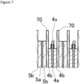
- the first protrusion is arranged on a surface oriented toward a winding center side (winding inner side) of the first electrode core body on the first end side of the first electrode plate. Accordingly, stress is not easily applied to the first protrusion, and the first protrusion is not easily detached from the first electrode core body. Therefore, a highly reliable secondary battery in which the first electrode plate and the second electrode plate are effectively prevented from being short-circuited is obtained.
- a configuration of a rectangular secondary battery 20 as a secondary battery according to an embodiment will be described below.
- the present invention is not limited to the following embodiment.
- a positive electrode tab group 40A composed of a plurality of positive electrode tabs 40 and a negative electrode tab group 50A composed of a plurality of negative electrode tabs 50 are provided in an end portion on the sealing plate 2 side of the wound electrode assembly 3.
- the positive electrode tab group 40A is electrically connected to a positive electrode terminal 7 via a second positive electrode current collector 6b and a first positive electrode current collector 6a.
- the negative electrode tab group 50A is electrically connected to a negative electrode terminal 9 via a second negative electrode current collector 8b and a first negative electrode current collector 8a.
- the first positive electrode current collector 6a and the second positive electrode current collector 6b constitute a positive electrode current collector 6.
- the positive electrode current collector 6 may be one component.
- the first negative electrode current collector 8a and the second negative electrode current collector 8b constitute a negative electrode current collector 8.
- the negative electrode current collector 8 may be one component.
- the negative electrode active material layer slurry produced in the above-described method is applied to both surfaces of a copper foil having a thickness of 8 ⁇ m as a negative electrode core body with a die coater.
- FIG. 5(b) is a plan view of a negative electrode original plate 501 after tab formation.
- the negative electrode core body exposure part 5c in the negative electrode original plate 501 after tab formation is cut to a predetermined shape, to produce the negative electrode original plate 501 after tab formation.
- the negative electrode original plate 500 can be cut by irradiation of an energy beam such as a laser, a metal mold, a cutter (cutting blade), or the like.
- the plurality of negative electrode tabs 50 are formed in a longitudinal direction of the negative electrode original plate 501 after tab formation at both ends in a width direction of the negative electrode original plate 501 after tab formation.
- Each of the negative electrode tabs 50 is composed of the negative electrode core body exposure part 5c.
- the negative electrode original plate 500 is preferably cut by irradiation of an energy beam to form the negative electrode tabs 50.
- the first protrusion 4x can be effectively prevented from being detached from the positive electrode core body 4a.
- the protrusion height of the first protrusion 4x preferably changes along the first end side 4A. That is, a region where the protrusion height of the first protrusion 4x is partially small is preferably formed. As a result, stress to be applied to the first protrusion 4x can be reduced. Accordingly, the first protrusion 4x can be more effectively prevented from being detached from the positive electrode core body 4a.
- the protrusion height of the first protrusion 4x in the region where the protrusion height of the first protrusion 4x is partially small is preferably two-thirds or less and more preferably one-third or less the protrusion height of the first protrusion 4x in the portion where the protrusion height of the first protrusion 4x is the largest.
- the second protrusion having a smaller height than the protrusion height of the first protrusion 4x may be formed on a surface, oriented toward the winding outer side (outer peripheral side) of the wound electrode assembly 3, of the positive electrode core body 4a.
- the number of positive electrode tabs 40 to be laminated is preferably 0.8 ⁇ N1 or more and more preferably 0.9 ⁇ N1 or more.
- respective positive electrode tab groups 40A in two wound electrode assemblies 3 are connected to the second positive electrode current collector 6b, and respective negative electrode tab groups 50A in two wound electrode assemblies 3 are connected to the second negative electrode current collector 8b.
- the positive electrode tab groups 40A are bonded to the second positive electrode current collector 6b, to respectively form bonding parts 60.
- the negative electrode tab groups 50A are bonded to the second negative electrode current collector 8b, to respectively form bonding parts 61.
- ultrasonic welding ultrasonic bonding
- resistance welding resistance welding
- laser welding or the like
- a thin-walled part 6c is formed in the second positive electrode current collector 6b, and a current collector opening 6d is formed in the thin-walled part 6c.
- the second positive electrode current collector 6b is bonded to the first positive electrode current collector 6a.
- a current collector through hole 6e is formed at a position opposing the electrolyte injection hole 15 in the sealing plate 2.
- a thin-walled part 8c is formed in the second negative electrode current collector 8b, and a current collector opening 8d is formed in the thin-walled part 8c.
- the second negative electrode current collector 8b is bonded to the first negative electrode current collector 8a.
- FIG. 10 is a diagram illustrating a surface, on the inner side of the battery, of the sealing plate 2 to which each of components is attached. Each of the components is attached to the sealing plate 2 in the following manner.
- the outer-side insulating member 10 is arranged on the outer surface side of the battery around a positive electrode terminal insertion hole 2a of the sealing plate 2.
- the inner-side insulating member 11 and the first positive electrode current collector 6a are arranged on the inner surface side of the battery around the positive electrode terminal insertion hole 2a of the sealing plate 2.
- the positive electrode terminal 7 is inserted into a through hole of the outer-side insulating member 10, the positive electrode terminal insertion hole 2a of the sealing plate 2, a through hole of the inner-side insulating member 11, and a through hole of the first positive electrode current collector 6a from the outer side of the battery, to caulk a distal end of the positive electrode terminal 7 onto the first positive electrode current collector 6a.
- the positive electrode terminal 7 and the first positive electrode current collector 6a are fixed to the sealing plate 2.
- a portion caulked in the positive electrode terminal 7 and the first positive electrode current collector 6a are preferably welded to each other.
- the outer-side insulating member 12 is arranged on the outer surface side of the battery around a negative electrode terminal insertion hole 2b of the sealing plate 2.
- the inner-side insulating member 13 and the first negative electrode current collector 8a are arranged on the inner surface side of the battery around the negative electrode terminal insertion hole 2b of the sealing plate 2.
- the negative electrode terminal 9 is inserted into a through hole of the outer-side insulating member 12, the negative electrode terminal insertion hole 2b of the sealing plate 2, a through hole of the inner-side insulating member 13, and a through hole of the first negative electrode current collector 8a from the outer side of the battery, to caulk a distal end of the negative electrode terminal 9 onto the first negative electrode current collector 8a.
- the negative electrode terminal 9 and the first negative electrode current collector 8a are fixed to the sealing plate 2.
- a portion caulked in the negative electrode terminal 9 and the first negative electrode current collector 8a are preferably welded to each other.
- a portion, opposing the electrolyte injection hole 15 provided in the sealing plate 2, in the inner-side insulating member 11 is provided with an injection opening 11a.
- An edge portion of the injection opening 11a is provided with a cylindrical part 11b.
- FIG. 11 is a diagram illustrating a surface, on the inner side of the battery, of the sealing plate 2 after the second positive electrode current collector 6b is attached to the first positive electrode current collector 6a and the second negative electrode current collector 8b is attached to the first negative electrode current collector 8a.
- the second positive electrode current collector 6b to which the positive electrode tab groups 40A are connected is arranged on the inner-side insulating member 11 such that its part overlaps the first positive electrode current collector 6a.
- the thin-walled part 6c is irradiated with a laser, to bond the second positive electrode current collector 6b and the first positive electrode current collector 6a to each other.
- a bonding part 62 is formed.
- the second negative electrode current collector 8b to which the negative electrode tab groups 50A are connected is arranged on the inner-side insulating member 13 such that its part overlaps the first negative electrode current collector 8a.
- the thin-walled part 8c is irradiated with a laser, to bond the second negative electrode current collector 8b and the first negative electrode current collector 8a to each other.
- a bonding part 63 is formed.
- the two positive electrode tab groups 40A and the two negative electrode tab groups 50A are curved such that an upper surface of one of the wound electrode assemblies 3 and an upper surface of the other wound electrode assembly 3 in FIG. 11 contact each other directly or via another member. As a result, the two wound electrode assemblies 3 are integrated.
- the two wound electrode assemblies 3 are arranged in the electrode assembly holder 14 composed of the insulating sheet shaped in a box shape or a bag shape.
- the one positive electrode tab group 40A and the other positive electrode tab group 40A enter a state where they are respectively curved in different directions.
- the one negative electrode tab group 50A and the other negative electrode tab group 50A enter a state where they are respectively curved in different directions.
- the two wound electrode assemblies 3 wrapped by the electrode assembly holder 14 are inserted into the rectangular exterior member 1.
- the sealing plate 2 and the rectangular exterior member 1 are welded to each other, and the opening of the rectangular exterior member 1 is sealed with the sealing plate 2.
- An electrolyte is injected into the rectangular exterior member 1 via the electrolyte injection hole 15 provided in the sealing plate 2.
- the electrolyte injection hole 15 is sealed with the sealing member 16 such as a blind rivet.
- the rectangular secondary battery 20 is completed.
- the first protrusion 4x in the vicinity of the first end side 4A of the positive electrode plate 4 has been described.
- the invention of the present application is not limited to the positive electrode plate side.
- the negative electrode plate side can also have a configuration related to the first protrusion disclosed in the above-described embodiment.
- Both the positive electrode plate side and the negative electrode plate side can also each have the configuration related to the first protrusion disclosed in the above-described embodiment.
- the core body is made of aluminum or an aluminum alloy
- the protrusion height of the first protrusion easily becomes high. Accordingly, the invention of the present application is particularly effective when the core body is made of aluminum or an aluminum alloy.
- the number of wound electrode assemblies may be one, or may be three or more.
- each of the positive electrode current collector and the negative electrode current collector may be composed of one component. If each of the positive electrode current collector and the negative electrode current collector is composed of one component, the positive electrode current collector and the negative electrode current collector are preferably respectively connected to the positive electrode terminal and the negative electrode terminal attached to the sealing plate after the positive electrode tab group and the negative electrode tab group are respectively connected to the positive electrode current collector and the negative electrode current collector.
- Known materials can be respectively used for a positive electrode plate, a negative electrode plate, a separator, an electrolyte, and the like.
Landscapes
- Chemical & Material Sciences (AREA)
- Engineering & Computer Science (AREA)
- Chemical Kinetics & Catalysis (AREA)
- Electrochemistry (AREA)
- General Chemical & Material Sciences (AREA)
- Physics & Mathematics (AREA)
- Optics & Photonics (AREA)
- Manufacturing & Machinery (AREA)
- Plasma & Fusion (AREA)
- Mechanical Engineering (AREA)
- Materials Engineering (AREA)
- Secondary Cells (AREA)
- Connection Of Batteries Or Terminals (AREA)
- Cell Electrode Carriers And Collectors (AREA)
- Battery Electrode And Active Subsutance (AREA)
Claims (6)
- Batterie rechargeable (20) comprenant :une première plaque d'électrode en forme de bande (4) ayant une pluralité de premières pattes d'électrode (40) ;une deuxième plaque d'électrode en forme de bande (5) ayant une polarité différente de celle de la première plaque d'électrode (4) ;un assemblage d'électrodes enroulées de forme plate (3) obtenu par enroulement de la première plaque d'électrode (4) et de la deuxième plaque d'électrode (5) avec un séparateur en forme de bande (70) entre elles ; etun premier collecteur de courant d'électrode (6) connecté à la pluralité de premières pattes d'électrode (40) stratifiées,dans laquelle la première plaque d'électrode (4) a un premier corps de coeur d'électrode (4a) fait en métal et une première couche de matériau actif d'électrode (4b) formée sur le premier corps de coeur d'électrode (4a), etsur un premier côté d'extrémité (4A) de la première plaque d'électrode (4) sur lequel la pluralité de premières pattes d'électrode (40) sont disposées,une première saillie (4x) saillant dans la direction de l'épaisseur du premier corps de coeur d'électrode (4a) depuis une certaine surface du premier corps de coeur d'électrode (4a) est formée sur la certaine surface du premier corps de coeur d'électrode (4a) sauf là où se trouve la pluralité de premières pattes d'électrode (40),une saillie saillant dans la direction de l'épaisseur du premier corps de coeur d'électrode (4a) depuis l'autre surface du premier corps de coeur d'électrode (4a) n'est pas formée sur l'autre surface du premier corps de coeur d'électrode (4a), ou bien une deuxième saillie saillant dans la direction de l'épaisseur du premier corps de coeur d'électrode (4a) depuis l'autre surface du premier corps de coeur d'électrode (4a) et ayant une hauteur de saillie inférieure à la hauteur de saillie de la première saillie est formée sur l'autre surface du premier corps de coeur d'électrode (4a),la hauteur de saillie de la première saillie (4x) est inférieure à l'épaisseur de la première couche de matériau actif d'électrode (4b), etdans l'assemblage d'électrodes enroulées (3), la certaine surface du premier corps de coeur d'électrode (4a) est disposée de manière à être orientée vers le côté du centre d'enroulement de l'assemblage d'électrodes enroulées (3).
- Batterie rechargeable (20) selon la revendication 1, dans laquellela première plaque d'électrode (4) est une plaque d'électrode positive (4), etla deuxième plaque d'électrode (5) est une plaque d'électrode négative (5).
- Batterie rechargeable (20) selon la revendication 1 ou 2, dans laquelle la première patte d'électrode (40) fait partie du premier corps de coeur d'électrode (4a).
- Batterie rechargeable (20) selon l'une quelconque des revendications 1 à 3, dans laquelle le premier corps de coeur d'électrode (4a) est composé d'aluminium ou d'un alliage d'aluminium.
- Batterie rechargeable (20) selon l'une quelconque des revendications 1 à 4, dans laquelle la pluralité de premières pattes d'électrode (40) est connectée au premier collecteur de courant d'électrode (6) sous une forme incurvée.
- Batterie rechargeable (20) selon l'une quelconque des revendications 1 à 5, dans laquellele premier côté d'extrémité (4A) de la première plaque d'électrode (4) a une région de non-formation de couche de matériau actif (4f), où la première couche de matériau actif d'électrode (4b) n'est pas formée, dans le premier corps de coeur d'électrode (4a), etune première couche protectrice d'électrode (4c) est formée dans une portion, adjacente à la première couche de matériau actif d'électrode (4b), dans la région de non-formation de couche de matériau actif (4f).
Applications Claiming Priority (2)
| Application Number | Priority Date | Filing Date | Title |
|---|---|---|---|
| JP2018244060 | 2018-12-27 | ||
| PCT/JP2019/049493 WO2020137714A1 (fr) | 2018-12-27 | 2019-12-17 | Batterie secondaire |
Publications (3)
| Publication Number | Publication Date |
|---|---|
| EP3905382A1 EP3905382A1 (fr) | 2021-11-03 |
| EP3905382A4 EP3905382A4 (fr) | 2022-01-19 |
| EP3905382B1 true EP3905382B1 (fr) | 2024-11-20 |
Family
ID=71125915
Family Applications (1)
| Application Number | Title | Priority Date | Filing Date |
|---|---|---|---|
| EP19903727.6A Active EP3905382B1 (fr) | 2018-12-27 | 2019-12-17 | Batterie secondaire |
Country Status (5)
| Country | Link |
|---|---|
| US (1) | US12438242B2 (fr) |
| EP (1) | EP3905382B1 (fr) |
| JP (1) | JP7353302B2 (fr) |
| CN (1) | CN113169428B (fr) |
| WO (1) | WO2020137714A1 (fr) |
Families Citing this family (4)
| Publication number | Priority date | Publication date | Assignee | Title |
|---|---|---|---|---|
| JP7385639B2 (ja) * | 2021-10-29 | 2023-11-22 | プライムプラネットエナジー&ソリューションズ株式会社 | 電池 |
| JP7463333B2 (ja) * | 2021-11-17 | 2024-04-08 | プライムプラネットエナジー&ソリューションズ株式会社 | 電池 |
| CN117712635B (zh) * | 2022-04-28 | 2025-07-25 | 宁德时代新能源科技股份有限公司 | 电池单体、电池、用电设备、电极组件及其制造方法 |
| CN120202590A (zh) * | 2022-11-16 | 2025-06-24 | 株式会社Lg新能源 | 电极组件、包括其的电池及包括这种电池的电池组和车辆 |
Family Cites Families (21)
| Publication number | Priority date | Publication date | Assignee | Title |
|---|---|---|---|---|
| US6238819B1 (en) * | 1998-01-23 | 2001-05-29 | Stork, N.V. | Metal foam support, electrode and method of making same |
| JP4245205B2 (ja) * | 1998-03-18 | 2009-03-25 | 三洋電機株式会社 | 非水電解質電池 |
| JP3628888B2 (ja) * | 1998-10-30 | 2005-03-16 | トヨタ自動車株式会社 | 電極の集電構造 |
| JP2001203001A (ja) | 2000-01-18 | 2001-07-27 | Sony Corp | 非水電解質電池及びその製造方法 |
| JP2001266899A (ja) | 2000-03-24 | 2001-09-28 | Sanyo Electric Co Ltd | 長尺状電極板、円筒形電池及びそれらの製造方法 |
| JP3551365B2 (ja) * | 2000-06-20 | 2004-08-04 | 株式会社デンソー | 扁平形状巻回型電極電池 |
| JP4245429B2 (ja) * | 2003-08-11 | 2009-03-25 | 三洋電機株式会社 | 渦巻状電極群を備えた電池 |
| JP2010086807A (ja) * | 2008-09-30 | 2010-04-15 | Toshiba Corp | 非水電解質電池 |
| CN102035013B (zh) * | 2009-10-01 | 2014-08-13 | 三星Sdi株式会社 | 二次电池和制造二次电池的方法 |
| JP5621762B2 (ja) | 2011-12-20 | 2014-11-12 | 株式会社豊田自動織機 | 電極体、二次電池、及び車両 |
| JP6045286B2 (ja) | 2012-10-15 | 2016-12-14 | 日立オートモティブシステムズ株式会社 | 円筒形蓄電素子 |
| JP5954339B2 (ja) * | 2014-01-30 | 2016-07-20 | 三洋電機株式会社 | 角形二次電池及びその製造方法 |
| KR102177506B1 (ko) * | 2014-07-30 | 2020-11-11 | 삼성에스디아이 주식회사 | 이차 전지 및 그 제조 방법 |
| JP6520097B2 (ja) | 2014-12-11 | 2019-05-29 | 株式会社Gsユアサ | 蓄電素子 |
| JP6582489B2 (ja) * | 2015-03-30 | 2019-10-02 | 三洋電機株式会社 | 角形二次電池及びそれを用いた組電池 |
| JP6701627B2 (ja) * | 2015-05-22 | 2020-05-27 | 株式会社豊田自動織機 | 蓄電装置 |
| JP2017142896A (ja) * | 2016-02-08 | 2017-08-17 | トヨタ自動車株式会社 | 二次電池 |
| KR20180001229A (ko) | 2016-06-27 | 2018-01-04 | 삼성에스디아이 주식회사 | 이차 전지의 제조 방법 및 이를 이용한 이차 전지 |
| JP6931277B2 (ja) | 2016-08-31 | 2021-09-01 | 三洋電機株式会社 | 二次電池用電極の製造方法、及び二次電池の製造方法 |
| JP6241529B2 (ja) * | 2016-10-17 | 2017-12-06 | 三洋電機株式会社 | 非水電解質二次電池の製造方法 |
| JP2018073767A (ja) * | 2016-11-04 | 2018-05-10 | トヨタ自動車株式会社 | 二次電池の製造方法 |
-
2019
- 2019-12-17 EP EP19903727.6A patent/EP3905382B1/fr active Active
- 2019-12-17 CN CN201980076422.8A patent/CN113169428B/zh active Active
- 2019-12-17 WO PCT/JP2019/049493 patent/WO2020137714A1/fr not_active Ceased
- 2019-12-17 JP JP2020563120A patent/JP7353302B2/ja active Active
- 2019-12-17 US US17/415,139 patent/US12438242B2/en active Active
Also Published As
| Publication number | Publication date |
|---|---|
| EP3905382A4 (fr) | 2022-01-19 |
| CN113169428A (zh) | 2021-07-23 |
| EP3905382A1 (fr) | 2021-11-03 |
| JPWO2020137714A1 (ja) | 2021-11-11 |
| JP7353302B2 (ja) | 2023-09-29 |
| WO2020137714A1 (fr) | 2020-07-02 |
| CN113169428B (zh) | 2023-03-28 |
| US20220059911A1 (en) | 2022-02-24 |
| US12438242B2 (en) | 2025-10-07 |
Similar Documents
| Publication | Publication Date | Title |
|---|---|---|
| US12176530B2 (en) | Electrode plate and method for manufacturing same, and secondary battery and method for manufacturing same | |
| EP3902047B1 (fr) | Batterie secondaire rectangulaire | |
| EP3905382B1 (fr) | Batterie secondaire | |
| EP3902046A1 (fr) | Batterie secondaire et son procédé de fabrication | |
| US11978895B2 (en) | Secondary battery electrode plate comprising a protrusion and secondary battery using the same | |
| CN112970144B (zh) | 二次电池用的电极板和使用了该电极板的二次电池 | |
| US12237497B2 (en) | Electrode plate for secondary batteries, and secondary battery using same | |
| EP3905384A1 (fr) | Électrode plane et batterie secondaire comprenant cette dernière | |
| EP3902030B1 (fr) | Plaque d'électrode de batterie secondaire et batterie secondaire l'utilisant |
Legal Events
| Date | Code | Title | Description |
|---|---|---|---|
| STAA | Information on the status of an ep patent application or granted ep patent |
Free format text: STATUS: THE INTERNATIONAL PUBLICATION HAS BEEN MADE |
|
| PUAI | Public reference made under article 153(3) epc to a published international application that has entered the european phase |
Free format text: ORIGINAL CODE: 0009012 |
|
| STAA | Information on the status of an ep patent application or granted ep patent |
Free format text: STATUS: REQUEST FOR EXAMINATION WAS MADE |
|
| 17P | Request for examination filed |
Effective date: 20210623 |
|
| AK | Designated contracting states |
Kind code of ref document: A1 Designated state(s): AL AT BE BG CH CY CZ DE DK EE ES FI FR GB GR HR HU IE IS IT LI LT LU LV MC MK MT NL NO PL PT RO RS SE SI SK SM TR |
|
| REG | Reference to a national code |
Ref country code: DE Ref legal event code: R079 Free format text: PREVIOUS MAIN CLASS: H01M0002260000 Ipc: H01M0004660000 Ref document number: 602019062413 Country of ref document: DE |
|
| A4 | Supplementary search report drawn up and despatched |
Effective date: 20211220 |
|
| RIC1 | Information provided on ipc code assigned before grant |
Ipc: B23K 103/10 20060101ALI20211214BHEP Ipc: B23K 103/12 20060101ALI20211214BHEP Ipc: B23K 101/36 20060101ALI20211214BHEP Ipc: B23K 26/40 20140101ALI20211214BHEP Ipc: B23K 26/38 20140101ALI20211214BHEP Ipc: B23K 26/32 20140101ALI20211214BHEP Ipc: B23K 26/21 20140101ALI20211214BHEP Ipc: H01M 50/531 20210101ALI20211214BHEP Ipc: B23K 26/00 20140101ALI20211214BHEP Ipc: H01M 50/534 20210101ALI20211214BHEP Ipc: H01M 50/533 20210101ALI20211214BHEP Ipc: H01M 4/70 20060101ALI20211214BHEP Ipc: H01M 10/0587 20100101ALI20211214BHEP Ipc: H01M 10/04 20060101ALI20211214BHEP Ipc: H01M 4/66 20060101AFI20211214BHEP |
|
| DAV | Request for validation of the european patent (deleted) | ||
| DAX | Request for extension of the european patent (deleted) | ||
| GRAP | Despatch of communication of intention to grant a patent |
Free format text: ORIGINAL CODE: EPIDOSNIGR1 |
|
| STAA | Information on the status of an ep patent application or granted ep patent |
Free format text: STATUS: GRANT OF PATENT IS INTENDED |
|
| INTG | Intention to grant announced |
Effective date: 20240613 |
|
| GRAS | Grant fee paid |
Free format text: ORIGINAL CODE: EPIDOSNIGR3 |
|
| GRAA | (expected) grant |
Free format text: ORIGINAL CODE: 0009210 |
|
| STAA | Information on the status of an ep patent application or granted ep patent |
Free format text: STATUS: THE PATENT HAS BEEN GRANTED |
|
| AK | Designated contracting states |
Kind code of ref document: B1 Designated state(s): AL AT BE BG CH CY CZ DE DK EE ES FI FR GB GR HR HU IE IS IT LI LT LU LV MC MK MT NL NO PL PT RO RS SE SI SK SM TR |
|
| REG | Reference to a national code |
Ref country code: GB Ref legal event code: FG4D |
|
| REG | Reference to a national code |
Ref country code: CH Ref legal event code: EP |
|
| REG | Reference to a national code |
Ref country code: DE Ref legal event code: R096 Ref document number: 602019062413 Country of ref document: DE |
|
| REG | Reference to a national code |
Ref country code: IE Ref legal event code: FG4D |
|
| REG | Reference to a national code |
Ref country code: LT Ref legal event code: MG9D |
|
| REG | Reference to a national code |
Ref country code: NL Ref legal event code: MP Effective date: 20241120 |
|
| PG25 | Lapsed in a contracting state [announced via postgrant information from national office to epo] |
Ref country code: PT Free format text: LAPSE BECAUSE OF FAILURE TO SUBMIT A TRANSLATION OF THE DESCRIPTION OR TO PAY THE FEE WITHIN THE PRESCRIBED TIME-LIMIT Effective date: 20250320 Ref country code: HR Free format text: LAPSE BECAUSE OF FAILURE TO SUBMIT A TRANSLATION OF THE DESCRIPTION OR TO PAY THE FEE WITHIN THE PRESCRIBED TIME-LIMIT Effective date: 20241120 Ref country code: IS Free format text: LAPSE BECAUSE OF FAILURE TO SUBMIT A TRANSLATION OF THE DESCRIPTION OR TO PAY THE FEE WITHIN THE PRESCRIBED TIME-LIMIT Effective date: 20250320 |
|
| PG25 | Lapsed in a contracting state [announced via postgrant information from national office to epo] |
Ref country code: FI Free format text: LAPSE BECAUSE OF FAILURE TO SUBMIT A TRANSLATION OF THE DESCRIPTION OR TO PAY THE FEE WITHIN THE PRESCRIBED TIME-LIMIT Effective date: 20241120 Ref country code: NL Free format text: LAPSE BECAUSE OF FAILURE TO SUBMIT A TRANSLATION OF THE DESCRIPTION OR TO PAY THE FEE WITHIN THE PRESCRIBED TIME-LIMIT Effective date: 20241120 |
|
| REG | Reference to a national code |
Ref country code: AT Ref legal event code: MK05 Ref document number: 1744416 Country of ref document: AT Kind code of ref document: T Effective date: 20241120 |
|
| PG25 | Lapsed in a contracting state [announced via postgrant information from national office to epo] |
Ref country code: BG Free format text: LAPSE BECAUSE OF FAILURE TO SUBMIT A TRANSLATION OF THE DESCRIPTION OR TO PAY THE FEE WITHIN THE PRESCRIBED TIME-LIMIT Effective date: 20241120 |
|
| PG25 | Lapsed in a contracting state [announced via postgrant information from national office to epo] |
Ref country code: ES Free format text: LAPSE BECAUSE OF FAILURE TO SUBMIT A TRANSLATION OF THE DESCRIPTION OR TO PAY THE FEE WITHIN THE PRESCRIBED TIME-LIMIT Effective date: 20241120 |
|
| PG25 | Lapsed in a contracting state [announced via postgrant information from national office to epo] |
Ref country code: NO Free format text: LAPSE BECAUSE OF FAILURE TO SUBMIT A TRANSLATION OF THE DESCRIPTION OR TO PAY THE FEE WITHIN THE PRESCRIBED TIME-LIMIT Effective date: 20250220 |
|
| PG25 | Lapsed in a contracting state [announced via postgrant information from national office to epo] |
Ref country code: AT Free format text: LAPSE BECAUSE OF FAILURE TO SUBMIT A TRANSLATION OF THE DESCRIPTION OR TO PAY THE FEE WITHIN THE PRESCRIBED TIME-LIMIT Effective date: 20241120 Ref country code: GR Free format text: LAPSE BECAUSE OF FAILURE TO SUBMIT A TRANSLATION OF THE DESCRIPTION OR TO PAY THE FEE WITHIN THE PRESCRIBED TIME-LIMIT Effective date: 20250221 Ref country code: LV Free format text: LAPSE BECAUSE OF FAILURE TO SUBMIT A TRANSLATION OF THE DESCRIPTION OR TO PAY THE FEE WITHIN THE PRESCRIBED TIME-LIMIT Effective date: 20241120 |
|
| PG25 | Lapsed in a contracting state [announced via postgrant information from national office to epo] |
Ref country code: PL Free format text: LAPSE BECAUSE OF FAILURE TO SUBMIT A TRANSLATION OF THE DESCRIPTION OR TO PAY THE FEE WITHIN THE PRESCRIBED TIME-LIMIT Effective date: 20241120 |
|
| PG25 | Lapsed in a contracting state [announced via postgrant information from national office to epo] |
Ref country code: RS Free format text: LAPSE BECAUSE OF FAILURE TO SUBMIT A TRANSLATION OF THE DESCRIPTION OR TO PAY THE FEE WITHIN THE PRESCRIBED TIME-LIMIT Effective date: 20250220 |
|
| PG25 | Lapsed in a contracting state [announced via postgrant information from national office to epo] |
Ref country code: SM Free format text: LAPSE BECAUSE OF FAILURE TO SUBMIT A TRANSLATION OF THE DESCRIPTION OR TO PAY THE FEE WITHIN THE PRESCRIBED TIME-LIMIT Effective date: 20241120 |
|
| PG25 | Lapsed in a contracting state [announced via postgrant information from national office to epo] |
Ref country code: DK Free format text: LAPSE BECAUSE OF FAILURE TO SUBMIT A TRANSLATION OF THE DESCRIPTION OR TO PAY THE FEE WITHIN THE PRESCRIBED TIME-LIMIT Effective date: 20241120 |
|
| PG25 | Lapsed in a contracting state [announced via postgrant information from national office to epo] |
Ref country code: EE Free format text: LAPSE BECAUSE OF FAILURE TO SUBMIT A TRANSLATION OF THE DESCRIPTION OR TO PAY THE FEE WITHIN THE PRESCRIBED TIME-LIMIT Effective date: 20241120 |
|
| PG25 | Lapsed in a contracting state [announced via postgrant information from national office to epo] |
Ref country code: RO Free format text: LAPSE BECAUSE OF FAILURE TO SUBMIT A TRANSLATION OF THE DESCRIPTION OR TO PAY THE FEE WITHIN THE PRESCRIBED TIME-LIMIT Effective date: 20241120 |
|
| PG25 | Lapsed in a contracting state [announced via postgrant information from national office to epo] |
Ref country code: SK Free format text: LAPSE BECAUSE OF FAILURE TO SUBMIT A TRANSLATION OF THE DESCRIPTION OR TO PAY THE FEE WITHIN THE PRESCRIBED TIME-LIMIT Effective date: 20241120 |
|
| PG25 | Lapsed in a contracting state [announced via postgrant information from national office to epo] |
Ref country code: CZ Free format text: LAPSE BECAUSE OF FAILURE TO SUBMIT A TRANSLATION OF THE DESCRIPTION OR TO PAY THE FEE WITHIN THE PRESCRIBED TIME-LIMIT Effective date: 20241120 |
|
| PG25 | Lapsed in a contracting state [announced via postgrant information from national office to epo] |
Ref country code: IT Free format text: LAPSE BECAUSE OF FAILURE TO SUBMIT A TRANSLATION OF THE DESCRIPTION OR TO PAY THE FEE WITHIN THE PRESCRIBED TIME-LIMIT Effective date: 20241120 |
|
| REG | Reference to a national code |
Ref country code: CH Ref legal event code: PL |
|
| PG25 | Lapsed in a contracting state [announced via postgrant information from national office to epo] |
Ref country code: LU Free format text: LAPSE BECAUSE OF NON-PAYMENT OF DUE FEES Effective date: 20241217 |
|
| REG | Reference to a national code |
Ref country code: DE Ref legal event code: R097 Ref document number: 602019062413 Country of ref document: DE |
|
| PG25 | Lapsed in a contracting state [announced via postgrant information from national office to epo] |
Ref country code: SE Free format text: LAPSE BECAUSE OF FAILURE TO SUBMIT A TRANSLATION OF THE DESCRIPTION OR TO PAY THE FEE WITHIN THE PRESCRIBED TIME-LIMIT Effective date: 20241120 |
|
| PG25 | Lapsed in a contracting state [announced via postgrant information from national office to epo] |
Ref country code: MC Free format text: LAPSE BECAUSE OF FAILURE TO SUBMIT A TRANSLATION OF THE DESCRIPTION OR TO PAY THE FEE WITHIN THE PRESCRIBED TIME-LIMIT Effective date: 20241120 |
|
| PLBE | No opposition filed within time limit |
Free format text: ORIGINAL CODE: 0009261 |
|
| STAA | Information on the status of an ep patent application or granted ep patent |
Free format text: STATUS: NO OPPOSITION FILED WITHIN TIME LIMIT |
|
| REG | Reference to a national code |
Ref country code: BE Ref legal event code: MM Effective date: 20241231 |
|
| PG25 | Lapsed in a contracting state [announced via postgrant information from national office to epo] |
Ref country code: BE Free format text: LAPSE BECAUSE OF NON-PAYMENT OF DUE FEES Effective date: 20241231 |
|
| PG25 | Lapsed in a contracting state [announced via postgrant information from national office to epo] |
Ref country code: CH Free format text: LAPSE BECAUSE OF NON-PAYMENT OF DUE FEES Effective date: 20241231 |
|
| 26N | No opposition filed |
Effective date: 20250821 |
|
| PG25 | Lapsed in a contracting state [announced via postgrant information from national office to epo] |
Ref country code: IE Free format text: LAPSE BECAUSE OF NON-PAYMENT OF DUE FEES Effective date: 20241217 |
|
| PGFP | Annual fee paid to national office [announced via postgrant information from national office to epo] |
Ref country code: DE Payment date: 20251211 Year of fee payment: 7 |
|
| PGFP | Annual fee paid to national office [announced via postgrant information from national office to epo] |
Ref country code: GB Payment date: 20251219 Year of fee payment: 7 |
|
| PGFP | Annual fee paid to national office [announced via postgrant information from national office to epo] |
Ref country code: FR Payment date: 20251229 Year of fee payment: 7 |