EP3905606B1 - Communication de sécurité dans un système de communication d'ascenseur - Google Patents
Communication de sécurité dans un système de communication d'ascenseur Download PDFInfo
- Publication number
- EP3905606B1 EP3905606B1 EP20172443.2A EP20172443A EP3905606B1 EP 3905606 B1 EP3905606 B1 EP 3905606B1 EP 20172443 A EP20172443 A EP 20172443A EP 3905606 B1 EP3905606 B1 EP 3905606B1
- Authority
- EP
- European Patent Office
- Prior art keywords
- safety
- elevator
- master node
- ethernet bus
- node
- Prior art date
- Legal status (The legal status is an assumption and is not a legal conclusion. Google has not performed a legal analysis and makes no representation as to the accuracy of the status listed.)
- Active
Links
Images


Classifications
-
- B—PERFORMING OPERATIONS; TRANSPORTING
- B66—HOISTING; LIFTING; HAULING
- B66B—ELEVATORS; ESCALATORS OR MOVING WALKWAYS
- B66B1/00—Control systems of elevators in general
- B66B1/34—Details, e.g. call counting devices, data transmission from car to control system, devices giving information to the control system
- B66B1/3415—Control system configuration and the data transmission or communication within the control system
- B66B1/3446—Data transmission or communication within the control system
-
- H—ELECTRICITY
- H04—ELECTRIC COMMUNICATION TECHNIQUE
- H04L—TRANSMISSION OF DIGITAL INFORMATION, e.g. TELEGRAPHIC COMMUNICATION
- H04L12/00—Data switching networks
- H04L12/28—Data switching networks characterised by path configuration, e.g. LAN [Local Area Networks] or WAN [Wide Area Networks]
- H04L12/40—Bus networks
- H04L12/403—Bus networks with centralised control, e.g. polling
-
- G—PHYSICS
- G08—SIGNALLING
- G08B—SIGNALLING SYSTEMS, e.g. PERSONAL CALLING SYSTEMS; ORDER TELEGRAPHS; ALARM SYSTEMS
- G08B26/00—Alarm systems in which substations are interrogated in succession by a central station
-
- B—PERFORMING OPERATIONS; TRANSPORTING
- B66—HOISTING; LIFTING; HAULING
- B66B—ELEVATORS; ESCALATORS OR MOVING WALKWAYS
- B66B1/00—Control systems of elevators in general
- B66B1/34—Details, e.g. call counting devices, data transmission from car to control system, devices giving information to the control system
- B66B1/3415—Control system configuration and the data transmission or communication within the control system
- B66B1/3446—Data transmission or communication within the control system
- B66B1/3453—Procedure or protocol for the data transmission or communication
-
- B—PERFORMING OPERATIONS; TRANSPORTING
- B66—HOISTING; LIFTING; HAULING
- B66B—ELEVATORS; ESCALATORS OR MOVING WALKWAYS
- B66B5/00—Applications of checking, fault-correcting, or safety devices in elevators
- B66B5/0006—Monitoring devices or performance analysers
- B66B5/0018—Devices monitoring the operating condition of the elevator system
- B66B5/0031—Devices monitoring the operating condition of the elevator system for safety reasons
-
- H—ELECTRICITY
- H04—ELECTRIC COMMUNICATION TECHNIQUE
- H04L—TRANSMISSION OF DIGITAL INFORMATION, e.g. TELEGRAPHIC COMMUNICATION
- H04L12/00—Data switching networks
- H04L12/02—Details
- H04L12/16—Arrangements for providing special services to substations
- H04L12/18—Arrangements for providing special services to substations for broadcast or conference, e.g. multicast
- H04L12/1863—Arrangements for providing special services to substations for broadcast or conference, e.g. multicast comprising mechanisms for improved reliability, e.g. status reports
-
- H—ELECTRICITY
- H04—ELECTRIC COMMUNICATION TECHNIQUE
- H04L—TRANSMISSION OF DIGITAL INFORMATION, e.g. TELEGRAPHIC COMMUNICATION
- H04L12/00—Data switching networks
- H04L12/02—Details
- H04L12/16—Arrangements for providing special services to substations
- H04L12/18—Arrangements for providing special services to substations for broadcast or conference, e.g. multicast
- H04L12/1895—Arrangements for providing special services to substations for broadcast or conference, e.g. multicast for short real-time information, e.g. alarms, notifications, alerts, updates
-
- H—ELECTRICITY
- H04—ELECTRIC COMMUNICATION TECHNIQUE
- H04L—TRANSMISSION OF DIGITAL INFORMATION, e.g. TELEGRAPHIC COMMUNICATION
- H04L12/00—Data switching networks
- H04L12/28—Data switching networks characterised by path configuration, e.g. LAN [Local Area Networks] or WAN [Wide Area Networks]
- H04L12/44—Star or tree networks
-
- H—ELECTRICITY
- H04—ELECTRIC COMMUNICATION TECHNIQUE
- H04L—TRANSMISSION OF DIGITAL INFORMATION, e.g. TELEGRAPHIC COMMUNICATION
- H04L63/00—Network architectures or network communication protocols for network security
- H04L63/20—Network architectures or network communication protocols for network security for managing network security; network security policies in general
-
- H—ELECTRICITY
- H04—ELECTRIC COMMUNICATION TECHNIQUE
- H04L—TRANSMISSION OF DIGITAL INFORMATION, e.g. TELEGRAPHIC COMMUNICATION
- H04L67/00—Network arrangements or protocols for supporting network services or applications
- H04L67/01—Protocols
- H04L67/12—Protocols specially adapted for proprietary or special-purpose networking environments, e.g. medical networks, sensor networks, networks in vehicles or remote metering networks
-
- H—ELECTRICITY
- H04—ELECTRIC COMMUNICATION TECHNIQUE
- H04L—TRANSMISSION OF DIGITAL INFORMATION, e.g. TELEGRAPHIC COMMUNICATION
- H04L12/00—Data switching networks
- H04L12/28—Data switching networks characterised by path configuration, e.g. LAN [Local Area Networks] or WAN [Wide Area Networks]
- H04L12/44—Star or tree networks
- H04L2012/445—Star or tree networks with switching in a hub, e.g. ETHERNET switch
Definitions
- the solution relates to the field of elevator communication systems. More specifically, the solution relates to safety communication in an elevator communication system.
- an elevator controller may receive information from call buttons and then control an elevator drive to serve calls, or the elevator controller may receive information from a safety circuit and then based on this information control one or more entities of the elevator system. These are only some possible examples of situations where information is received and/or sent within an elevator system.
- an elevator system may comprise multiple different internal data transmission solutions. This may mean that multiple different communication stacks and multiple different physical layers may be used simultaneously. The use of multiple different internal data transmission solutions may result in a complicated and inefficient solution. Further, in current solutions safety related data may be sent using a dedicated communication path between various safety related elements using a complicated communication protocol. This can mean that a separate safety communication system is needed in isolation of other elevator communication system(s), which may be complicated, expensive and increases overall latency in the elevator communication system.
- EP 3492419 A1 discloses an elevator safety system, an elevator system comprising an elevator safety system and to a method of operating an elevator safety system. The elevator safety system allows reducing the amount of data communicated via the communication bus without deteriorating the safety of the elevator system.
- an elevator communication system comprising an ethernet bus, a safety master node communicatively connected to the ethernet bus and configured to communicate via the ethernet bus, safety slave nodes communicatively connected to the ethernet bus and configured to communicate via the ethernet bus.
- the safety master node and the safety slave nodes are configured to communicate by using a time-triggered communication protocol.
- the safety master node is configured to send a polling diagnostic request message to the safety slave nodes by using a predetermined polling cycle.
- the safety master node is configured to send a broadcast diagnostic request message as the polling diagnostic request message to the safety slave nodes, and each of the safety slave nodes is configured to respond with a diagnostic reply message.
- the polling cycle depends on an operational status of an elevator car.
- the safety slave nodes are divided into at least two different polling groups having group specific polling cycles.
- the safety master node and the safety slave nodes are configured to communicate by using both the time-triggered communication protocol and an event-triggered communication protocol, wherein in the event-triggered communication protocol a safety slave node of the safety slave nodes is configured to send a status change message associated with the safety slave node to the safety master node in response to monitoring a status change.
- each of the safety slave nodes is configured to respond with the diagnostic reply message within a dedicated time window.
- the total polling cycle time may be adjustable such that the total cycle time is lengthened when new safety slave nodes are added to the bus segment.
- the safety master node when receiving no diagnostic reply message from a safety slave node within a dedicated time window, is configured to send a dedicated diagnostic request message to the safety slave node.
- the diagnostic reply message comprises a status indication associated with the safety slave node.
- the safety master node in the event-triggered communication protocol is configured to reply with an acknowledgement message to the safety slave node upon receipt of the status change message.
- the safety slave node in the event-triggered communication protocol is configured to repeat sending of the message to the safety master node until receiving an acknowledgement message from the safety master node.
- the safety master node is configured to divide the safety slave nodes into at least two groups and to apply a group-specific polling cycle for the at least two groups.
- the ethernet bus comprises a multi-drop ethernet bus segment, and the safety slave nodes are connected to the multi-drop ethernet bus segment.
- the elevator communication system further comprises a multi-drop ethernet bus segment communicatively connected to the ethernet bus and wherein the ethernet bus comprises a point-to-point ethernet bus, wherein at least one of the safety slave nodes is communicatively connected to the ethernet bus via the multi-drop ethernet bus segment.
- the safety master node is connected to the point-to-point ethernet bus.
- the ethernet bus comprises a multi-drop ethernet bus segment.
- both in the time-triggered communication protocol and in the event-triggered communication protocol turnaround time of the messaging between the safety master node and the safety slave nodes is determined to analyze bus traffic.
- a message from a safety slave node comprises a sequence number of last event data.
- the safety master node is configured to perform a safety shutdown of an elevator based on a message received from a safety slave node.
- a safety slave node of the safety slave nodes comprises one of the following: a node associated with an elevator shaft side entity; a node associated with an elevator car; and a node associated with a machinery entity.
- the safety slave node comprise a connector or an interface for connecting to a safety device or safety sensor, for example, a safety contact of an elevator safety chain.
- the safety slave node is integrated with the safety device or the safety sensor.
- a method for safety communication in an elevator communication system comprising an ethernet bus, a safety master node communicatively connected to the ethernet bus and configured to communicate via the ethernet bus, safety slaves nodes communicatively connected to the ethernet bus and configured to communicate via the ethernet bus.
- the method comprises communicating with the safety master node and the safety slave nodes by using a time-triggered communication protocol; sending by the safety master node in the time-triggered communication protocol a polling diagnostic request message to the safety slave nodes by using a predetermined polling cycle, sending by the safety master node a broadcast diagnostic request message as the polling diagnostic request message as to the safety slave nodes, and sending, by each of the safety slave nodes, a diagnostic reply message as a response message.
- the method further comprises communicating with the safety master node and the safety slave nodes by using both the time-triggered communication protocol and an event-triggered communication protocol, wherein in the event-triggered communication protocol sending, by a safety slave node of the safety slave nodes, a status change message associated with the safety slave node to the safety master node in response to monitoring a status change.
- the following description illustrates an elevator communication system that comprises an ethernet bus, a safety master node communicatively connected to the ethernet bus and configured to communicate via the ethernet bus, and safety slave nodes communicatively connected to the ethernet bus and configured to communicate via the ethernet bus.
- the safety master node and the safety slave nodes are configured to communicate by using a time-triggered communication protocol. Further, in the time-triggered communication protocol the safety master node is configured to send a polling diagnostic request message to the safety slave nodes by using a predetermined polling cycle.
- the safety master node and the safety slave nodes are configured to communicate by using both the time-triggered communication protocol and an event-triggered communication protocol, wherein in the event-triggered communication protocol a safety slave node of the safety slave nodes is configured to send a status change message associated with the safety slave node to the safety master node in response to monitoring a status change.
- the illustrated solution enables separating diagnostic messages from event associated messages.
- the various embodiments discussed below may be used in an elevator system comprising an elevator that is suitable and may be used for transferring passengers between landing floors of a building in response to service requests.
- the various embodiments discussed below may be used in an elevator system comprising an elevator that is suitable and may be used for automated transferring of passengers between landings in response to service requests.
- FIG. 1A illustrates an elevator communication system according to an example embodiment.
- the elevator communication system comprises a point-to-point ethernet bus 100 and at least one connecting unit 102A, 102B, 102C.
- One of more of the at least one connecting unit 102A, 102B, 102C may comprise a first port connected to a multi-drop ethernet bus segment 112A, 112B and a second port connected to the point-to-point ethernet bus 100.
- the connecting units 102A, 102B, 102C one or more multi-drop ethernet bus segments 112A, 112B may be connected to the point-to-point ethernet bus 100.
- the connecting unit 102A, 102B, 102C may refer, for example, to a switch, a hub or a router.
- the point-to-point ethernet bus 100 may be connected to an elevator controller.
- the point-to-point ethernet bus 100 may be, for example, 100BASE-TX or 10BASET1L point-to-point ethernet bus.
- the multi-drop ethernet bus segment 112A, 112B may comprise, for example, 10BASE-T1S multi-drop ethernet bus.
- the elevator communication system further comprises a safety master node 104 connected to the connecting unit 102A, and safety slave nodes 106A, 106B, 106C, 110A.
- the safety slave nodes 106A, 106B, 106C may be connected to the multi-drop ethernet bus segment 112A and the safety slave nodes 110A, 110B, 110C may be connected to the multi-drop ethernet bus segment 112B.
- the safety master node 104 may be separate from an elevator controller or it may be integrated with the elevator controller to form a single entity.
- the safety master node 104 may be a programmable safety controller configured to implement safety integrity level 3 (SIL 3) in accordance with norm IEC 61508.
- SIL 3 safety integrity level 3
- the safety master node 104 may be configured to selectively allow or prevent elevator operation based on the information received from the safety slave nodes.
- the safety master node 104 may be configured to perform safety shutdown of an elevator if an operational anomaly of the elevator has been detected.
- the safety shutdown may comprise activating hoisting machine brakes and interrupting power supply to hoisting motor.
- the safety master node 104 may be a separate control entity or it may integrated with another elevator control unit.
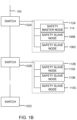
- FIG. 1B illustrates an elevator communication system according to an example embodiment.
- the elevator communication system comprises a point-to-point ethernet bus 100 and at least one connecting unit 102A, 102B, 102C.
- One or more of the at least one connecting unit 102A, 102B, 102C may comprise a first port connected to a multi-drop ethernet bus segment 112A, 112B and a second port connected to the point-to-point ethernet bus 100.
- the connecting units 102A, 102B, 102C one or more multi-drop ethernet bus segments 112A, 112B may be connected to the point-to-point ethernet bus 100.
- the connecting unit 102A, 102B, 102C may refer, for example, to a switch, a hub or a router.
- the point-to-point ethernet bus 100 may be connected to an elevator controller.
- the point-to-point ethernet bus 100 may be, for example, 100BASE-TX or 10BASET1L point-to-point ethernet bus.
- the multi-drop ethernet bus segment 112A, 112B may comprise, for example, 10BASE-T1S multi-drop ethernet bus.
- the elevator communication system further comprises a safety master node 114 connected to the multi-drop ethernet bus segment 112A, and safety slave nodes, 106B, 106C, 110A, 110B, 110C.
- the safety slave nodes 106B, 106C may be connected to the multi-drop ethernet bus segment 112A and the safety slave nodes 110A, 110B, 110C may be connected to the multi-drop ethernet bus segment 112B.
- the safety master node 104 may be a programmable safety controller configured to implement safety integrity level 3 (SIL 3) in accordance with norm IEC 61508. It may be configured to selectively allow or prevent elevator operation based on the information received from the safety slave nodes.
- SIL 3 safety integrity level 3
- the safety master node 104 may be configured to perform safety shutdown of an elevator if an operational anomaly of the elevator has been detected.
- the safety shutdown may comprise activating hoisting machine brakes and interrupting power supply to hoisting motor.
- the safety master node 104 may be a separate control entity or it may integrated with another elevator control unit.
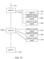
- FIG. 1C illustrates an elevator communication system according to an example embodiment.
- the elevator communication system comprises a point-to-point ethernet bus 100 and at least one connecting unit 102A, 102B, 102C.
- One of more of the at least one connecting unit 102A, 102B, 102C may comprise a first port connected to a multi-drop ethernet bus segment 112A, 112B and a second port connected to the point-to-point ethernet bus 100.
- the connecting units 102A, 102B, 102C one or more multi-drop ethernet bus segments 112A, 112B may be connected to the point-to-point ethernet bus 100.
- the connecting unit 102A, 102B, 102C may refer, for example, to a switch, a hub or a router.
- the point-to-point ethernet bus 100 may be connected to an elevator controller.
- the point-to-point ethernet bus 100 may be, for example, 100BASE-TX or 10BASET1L point-to-point ethernet bus.
- the multi-drop ethernet bus segment 112A, 112B may comprise, for example, 10BASE-T1S multi-drop ethernet bus.
- the elevator communication system further comprises a safety master node 114 connected to the multi-drop ethernet bus segment 112A, and safety slave nodes 106B, 106C connected to the multi-drop ethernet bus segment 112A.
- Safety slave nodes 116A, 116B, 116C are separately connected to the point-to-point ethernet bus 100 via the connecting unit 102B.
- the safety master node 114 may be a programmable safety controller configured to implement safety integrity level 3 (SIL 3) in accordance with norm IEC 61508. It may be configured to selectively allow or prevent elevator operation based on the information received from the safety slave nodes.
- SIL 3 safety integrity level 3
- the safety master node 114 may be configured to perform safety shutdown of an elevator if an operational anomaly of the elevator has been detected.
- the safety shutdown may comprise activating hoisting machine brakes and interrupting power supply to hoisting motor.
- the safety master node 114 may be a separate control entity or it may integrated with another elevator control unit.
- the connecting unit 102A, 102B, 102C may comprise an interface for directly interfacing, i.e. without an additional ethernet segment therebetween, with a safety sensor or a safety device.
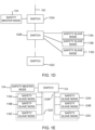
- FIG. 1D illustrates an elevator communication system according to an example embodiment.
- the elevator communication system comprises a point-to-point ethernet bus 100 and at least one connecting unit 102A, 102B, 102C. Further, the point-to-point ethernet bus 100 may be connected to an elevator controller.
- the point-to-point ethernet bus 100 may be, for example, 100BASE-TX or 10BASET1L point-to-point ethernet bus.
- the elevator communication system further comprises a safety master node 104 connected to the connecting unit 102A, and safety slave nodes 116A, 116B, 116C that are separately connected to the point-to-point ethernet bus 100 via the connecting unit 102B.
- the safety master node 104 may be a programmable safety controller configured to implement safety integrity level 3 (SIL 3) in accordance with norm IEC 61508. It may be configured to selectively allow or prevent elevator operation based on the information received from the safety slave nodes.
- the safety master node 104 may be configured to perform safety shutdown of an elevator if an operational anomaly of the elevator has been detected. The safety shutdown may comprise activating hoisting machine brakes and interrupting power supply to hoisting motor.
- the safety master node 104 may be a separate control entity or it may integrated with another elevator control unit.
- FIG. 1E illustrates an elevator communication system according to an example embodiment.
- the elevator communication system comprises a connecting unit 124, for example, a switch, a hub or a router.
- the elevator communication system further comprises one or more multi-drop ethernet bus segments 122A, 122B connected to the connecting unit 124.
- the multi-drop ethernet bus segment 122A, 122B may comprise, for example, 10BASE-T1S multi-drop ethernet bus.
- the elevator communication system further comprises a safety master node 104 connected to the connecting unit 124, and safety slave nodes 118A, 118B, 118C connected to the multi-drop ethernet bus segment 122A and safety slave nodes 120A, 120B, 120C connected to the multi-drop ethernet bus segment 122B.
- the safety master node 104 may be a programmable safety controller configured to implement safety integrity level 3 (SIL 3) in accordance with norm IEC 61508. It may be configured to selectively allow or prevent elevator operation based on the information received from the safety slave nodes.
- the safety master node 104 may be configured to perform safety shutdown of an elevator if an operational anomaly of the elevator has been detected. The safety shutdown may comprise activating hoisting machine brakes and interrupting power supply to hoisting motor.
- the safety master node 104 may be a separate control entity or it may integrated with another elevator control unit.
- FIG. 1F illustrates an elevator communication system according to an example embodiment.
- the elevator communication system comprises a connecting unit 130, for example, a switch, a hub or a router.
- the connecting unit 130 may be connected to an ethernet bus 132.
- the elevator communication system further comprises a safety master node 128 connected to the connecting unit 130, and safety slave nodes 126A, 126B, 126C connected directly to the safety master node 128.
- FIG. 2A illustrates a block diagram of a method for safety communication in an elevator communication system according to an example embodiment. The method may be implemented in any of the systems illustrated in FIGS. 1A - 1F .
- the safety master node and the safety slave nodes communicate by using a time-triggered communication protocol.
- the safety master node sends in the time-triggered communication protocol a polling diagnostic request message to the safety slave nodes by using a predetermined polling cycle.
- FIG. 2B illustrates a block diagram of a method for safety communication in an elevator communication system according to another example embodiment. The method may be implemented in any of the systems illustrated in FIGS. 1A - 1F .
- the safety master node and the safety slave nodes communicate by using both a time-triggered communication protocol and an event-triggered communication protocol.
- the safety master node sends in the time-triggered communication protocol a polling diagnostic request message to the safety slave nodes by using a predetermined polling cycle.
- a safety slave node sends in the event-triggered communication protocol a status change message associated with the safety slave node to the safety master node in response to monitoring a status change.
- this may be applicable in small elevators. For example, in case of 30 slave nodes it is reasonable to use the time triggered protocol with, for example, a 33ms polling cycle which gives around 1ms window for each safety slave node message. When the number of safety slave nodes increases, the polling cycle can be relaxed and the sufficient reaction time can be guaranteed by using the event triggered communication. This may enable a solution in which the processing needed at the receiving master node will be decreased.
- the polling cycle depends on an operational status of an elevator car. This may mean, for example, that when an elevator is idle, a less frequent polling cycle may be adopted than in a situation when the elevator is operating. Alternatively, when an elevator car door and/or a landing door is open, a more frequent polling cycle of a door zone sensor may be adopted than when the door is closed. By polling the door zone sensor more frequently when the door is open, it may be ensured that elevator car does not leave the door zone with an open door, which could lead to a dangerous situation for a passenger.
- the safety slave nodes may be divided into at least two different polling groups having group specific polling cycles. For example, safety slaves nodes or safety devices disposed in an elevator car and in a pit may be polled with a 10ms polling cycle whereas safety devices disposed on landings (for example, safety contacts of landing doors) may be polled with a 100ms polling cycle.
- the status change message may comprise a sequence number of last event data. By means of the sequence number, an actual order of status changes in the safety slave node can be solved afterwards by the safety master node. This is useful because in some cases the order of the messages received may be different from the order of the messages sent.
- the illustrated solution may also enable separating diagnostic messages from event associated messages.
- the safety master node In the time-triggered communication protocol the safety master node is configured to send a broadcast diagnostic request message to the safety slave nodes, and each of the safety slave nodes is configured to respond with a diagnostic reply message.
- This polling cycle may be constant.
- the sending frequency and/respond frequency may be variable, and it may vary, for example, in accordance with a random generator. This may mean that the time-triggered communication protocol is less vulnerable to electromagnetic interference, such as common mode disturbance.
- the diagnostic reply message may comprise a status indication associated with the safety slave node.
- the reply message may comprise a sequence number of last event data. By means of the sequence number, an actual order of status changes in the safety slave node can be solved afterwards by the safety master node. This is useful because in some cases the order of the messages received may be different from the order of the messages sent.
- each of the safety slave nodes may be configured to respond with a diagnostic reply message within a dedicated time window.
- the time window may be safety slave node specific for nodes in the same multi-drop ethernet bus segment.
- the total polling cycle time may be adjustable such that the total cycle time is lengthened when new safety slave nodes are added to the bus segment.
- the safety master node in the event-triggered communication protocol the safety master node is configured to reply with an acknowledgement message to the safety slave node upon receipt of the status change message. If the safety slave node does not receive the acknowledgement message from the safety master node, the safety slave node may be configured to repeat sending of the message to the safety master node until receiving the acknowledgement message from the safety master node.
- the safety master node may be configured to divide the safety slave nodes into at least two groups and to apply a group-specific polling cycle for the at least two groups.
- Some safety slave nodes may have different diagnostics reaction time requirements. Thus, this enables implementing different diagnostic requirements by the safety master node to the different safety slave node groups. For example, for a door zone sensor the diagnostics requirement might be 100ms and for a floor node it might be 1s .
- both in the time-triggered communication protocol and in the event-triggered communication protocol turnaround time of the messaging between the safety master node and the safety slave nodes may be determined to analyze bus traffic.
- the turnaround time may mean here a time delay from sending a message to receiving a related reply message.
- the analysis may provide information, such as statistical information about operating characteristics of the bus. For example, if an average turnaround time starts to increase, for example, deviate from what is expected, a degraded operating condition of the bus may be determined. In such a situation, as a specific diagnostic time requirement is set for the safety communication, it may be necessary to take specified maintenance or repairing actions to ensure elevator safety. Thus a maintenance visit may be scheduled if degraded operating condition of the bus is determined or, in case of extensive degradation, the elevator operation may even be terminated.
- the safety master node may be configured to perform a safety shutdown of an elevator based on a message received from a safety slave node.
- the message from the safety slave node may indicate a crucial event that has an effect for the operation of the elevator.
- the safety master node may be configured to resume a normal elevator operation based on a message received from a safety slave node (for example, when closing of a safety contact indicates that a landing door has been closed and elevator safety integrity has been restored).
- a safety slave node of the safety slave nodes may comprise one of the following: a node associated with an elevator shaft side entity, a node associated with an elevator car, and a node associated with a machinery entity.
- a safety slave node may be connected to a landing door safety circuit, a voice intercom device, a destination operating panel, a camera, a pit inspection device, a balancing rope sensor, a diverting pulley sensor etc.
- the node associated with the elevator car may be connected to a car encode, a door zone sensor, a car door safety contact, a car controller board, a car display, a door operator etc.
- the node associated with the machinery entity may be connected to a drive unit, a machinery sensor, a brake switch etc.
- the safety slave node may comprise a connector or an interface for connecting to a safety device or safety sensor, in particular a safety contact of an elevator safety chain.
- the safety slave node may be integrated with the safety device or the safety sensor.
- At least some of the above discussed example embodiments may allow connecting hundreds of safety related floor (slave) nodes to a safety master node.
- the safety master node may be implemented with a relatively low cost microcontroller.
- the illustrated solution uses only a small fraction of communication bandwidth of the ethernet bus. Further, the illustrated solution allows to separate diagnostics in several groups. One group of safety slave nodes can be diagnosed (polled) more frequently than another group.
- Example embodiments may be implemented in software, hardware, application logic or a combination of software, hardware and application logic.
- the example embodiments can store information relating to various methods described herein. This information can be stored in one or more memories, such as a hard disk, optical disk, magneto-optical disk, RAM, and the like.
- One or more databases can store the information used to implement the example embodiments.
- the databases can be organized using data structures (e.g., records, tables, arrays, fields, graphs, trees, lists, and the like) included in one or more memories or storage devices listed herein.
- the methods described with respect to the example embodiments can include appropriate data structures for storing data collected and/or generated by the methods of the devices and subsystems of the example embodiments in one or more databases.
- All or a portion of the example embodiments can be conveniently implemented using one or more general purpose processors, microprocessors, digital signal processors, micro-controllers, and the like, programmed according to the teachings of the example embodiments, as will be appreciated by those skilled in the computer and/or software art(s).
- Appropriate software can be readily prepared by programmers of ordinary skill based on the teachings of the example embodiments, as will be appreciated by those skilled in the software art.
- the example embodiments can be implemented by the preparation of application-specific integrated circuits or by interconnecting an appropriate network of conventional component circuits, as will be appreciated by those skilled in the electrical art(s).
Landscapes
- Engineering & Computer Science (AREA)
- Automation & Control Theory (AREA)
- Computer Networks & Wireless Communication (AREA)
- Signal Processing (AREA)
- Computer Security & Cryptography (AREA)
- Computing Systems (AREA)
- Business, Economics & Management (AREA)
- Emergency Management (AREA)
- Physics & Mathematics (AREA)
- General Physics & Mathematics (AREA)
- General Health & Medical Sciences (AREA)
- Medical Informatics (AREA)
- Health & Medical Sciences (AREA)
- Computer Hardware Design (AREA)
- General Engineering & Computer Science (AREA)
- Indicating And Signalling Devices For Elevators (AREA)
- Small-Scale Networks (AREA)
Claims (19)
- Système de communication d'ascenseur, comprenant :un bus Ethernet (100, 132) ;un nœud maître de sécurité (104, 114, 128) connecté en communication au bus Ethernet (100, 132) et configuré pour communiquer via le bus Ethernet (100, 132) ;des nœuds asservis de sécurité (106A, 106B, 106C, 110A, 110B, 110C, 116A, 116B, 116C, 118A, 118B, 118C, 120A, 120B, 120C) connectés en communication au bus Ethernet (100, 132) et configurés pour communiquer via le bus Ethernet (100, 132) ;dans lequel le nœud maître de sécurité (104, 114, 128) et les nœuds asservis de sécurité (106A, 106B, 106C, 110A, 110B, 110C, 116A, 116B, 116C, 118A, 118B, 118C, 120A, 120B, 120C) sont configurés pour communiquer en utilisant un protocole de communication à déclenchement temporel,dans lequel dans le protocole de communication à déclenchement temporel, le nœud maître de sécurité (104, 114, 128) est configuré pour envoyer un message de demande de diagnostic de sondage aux nœuds asservis de sécurité (106A, 106B, 106C, 110A, 110B, 110C, 116A, 116B, 116C, 118A, 118B, 118C, 120A, 120B, 120C) en utilisant un cycle de sondage prédéterminé, etdans lequel dans le protocole de communication à déclenchement temporel, le nœud maître de sécurité (104, 114, 128) est configuré pour envoyer un message de demande de diagnostic de diffusion en tant que message de demande de diagnostic de sondage aux nœuds asservis de sécurité (106A, 106B, 106C, 110A, 110B, 110C, 116A, 116B, 116C, 118A, 118B, 118C, 120A, 120B, 120C), et chacun des nœuds asservis de sécurité (106A, 106B, 106C, 110A, 110B, 110C, 116A, 116B, 116C, 118A, 118B, 118C, 120A, 120B, 120C) est configuré pour répondre avec un message de réponse de diagnostic.
- Système de communication d'ascenseur selon la revendication 1, dans lequel le cycle de sondage dépend d'un état opérationnel d'une cabine d'ascenseur.
- Système de communication d'ascenseur selon la revendication 1 ou la revendication 2, dans lequel les nœuds asservis de sécurité (106A, 106B, 106C, 110A, 110B, 110C, 116A, 116B, 116C, 118A, 118B, 118C, 120A, 120B, 120C) sont divisés en au moins deux groupes de sondage différents présentant des cycles de sondage spécifiques au groupe.
- Système de communication d'ascenseur selon l'une quelconque des revendications 1 à 3, dans lequel le nœud maître de sécurité (104, 114, 128) et les nœuds asservis de sécurité (106A, 106B, 106C, 110A, 110B, 110C, 116A, 116B, 116C, 118A, 118B, 118C, 120A, 120B, 120C) sont configurés pour communiquer en utilisant à la fois le protocole de communication à déclenchement temporel et un protocole de communication à déclenchement par événement, dans lequel dans le protocole de communication à déclenchement par événement, un nœud asservi de sécurité parmi les nœuds asservis de sécurité (106A, 106B, 106C, 110A, 110B, 110C, 116A, 116B, 116C, 118A, 118B, 118C, 120A, 120B, 120C) est configuré pour envoyer un message de changement d'état associé au nœud asservi de sécurité au nœud maître de sécurité (104, 114, 128) en réponse à la surveillance d'un changement d'état.
- Système de communication d'ascenseur selon l'une quelconque des revendications 1 à 4, dans lequel chacun des nœuds asservis de sécurité (106A, 106B, 106C, 110A, 110B, 110C, 116A, 116B, 116C, 118A, 118B, 118C, 120A, 120B, 120C) est configuré pour répondre avec le message de réponse de diagnostic dans une fenêtre de temps dédiée.
- Système de communication d'ascenseur selon la revendication 5, dans lequel, lorsqu'aucun message de réponse de diagnostic n'est reçu en provenance d'un nœud asservi de sécurité dans une fenêtre de temps dédiée, le nœud maître de sécurité (104, 114, 128) est configuré pour envoyer un message de demande de diagnostic dédié au nœud asservi de sécurité.
- Système de communication d'ascenseur selon l'une quelconque des revendications 1 à 6, dans lequel le message de réponse de diagnostic comprend une indication d'état associée au nœud asservi de sécurité.
- Système de communication d'ascenseur selon l'une quelconque des revendications 1 à 7, dans lequel dans le protocole de communication à déclenchement par événement, le nœud maître de sécurité (104, 114, 128) est configuré pour répondre avec un message d'accusé de réception au nœud asservi de sécurité à réception du message de changement d'état.
- Système de communication d'ascenseur selon la revendication 8, dans lequel dans le protocole de communication à déclenchement par événement le nœud asservi de sécurité est configuré pour répéter l'envoi du message au nœud maître de sécurité (104, 114, 128) jusqu'à la réception d'un message d'accusé de réception en provenance du nœud maître de sécurité (104, 114, 128).
- Système de communication d'ascenseur selon l'une quelconque des revendications 1 à 9, dans lequel le nœud maître de sécurité (104, 114, 128) est configuré pour diviser les nœuds asservis de sécurité (106A, 106B, 106C, 110A, 110B, 110C, 116A, 116B, 116C, 118A, 118B, 118C, 120A, 120B, 120C) en au moins deux groupes et pour appliquer un cycle de sondage spécifique au groupe pour les au moins deux groupes.
- Système de communication d'ascenseur selon l'une quelconque des revendications 1 à 10, dans lequel le bus Ethernet comprend un segment de bus Ethernet multipoint (112A, 112B, 122A, 122B).
- Système de communication d'ascenseur selon l'une quelconque des revendications 1 à 11, dans lequel le système de communication d'ascenseur comprend en outre un segment de bus Ethernet multipoint (112A, 112B) connecté en communication au bus Ethernet (100, 132) et dans lequel le bus Ethernet (100, 132) comprend un bus Ethernet point à point, dans lequel au moins l'un des nœuds asservis de sécurité (106A, 106B, 106C, 110A, 110B, 110C, 116A, 116B, 116C, 118A, 118B, 118C, 120A, 120B, 120C) est connecté en communication au bus Ethernet (100, 132) via le segment de bus Ethernet multipoint (112A, 112B).
- Système de communication d'ascenseur selon la revendication 12, dans lequel le nœud maître de sécurité (104, 114, 128) est connecté au bus Ethernet point à point.
- Système de communication d'ascenseur selon l'une quelconque des revendications 1 à 13, dans lequel dans le protocole de communication à déclenchement temporel et dans le protocole de communication à déclenchement par événement le temps d'exécution de la messagerie entre le nœud maître de sécurité (104, 114, 128) et les nœuds asservis de sécurité (106A, 106B, 106C, 110A, 110B, 110C, 116A, 116B, 116C, 118A, 118B, 118C, 120A, 120B, 120C) est déterminé pour analyser le trafic de bus.
- Système de communication d'ascenseur selon l'une quelconque des revendications 1 à 14, dans lequel un message provenant du nœud asservi de sécurité comprend un numéro de séquence de dernières données d'événement.
- Système de communication d'ascenseur selon l'une quelconque des revendications 1 à 15, dans lequel le nœud maître de sécurité (104, 114, 128) est configuré pour mettre en œuvre une interruption de sécurité d'un ascenseur sur la base d'un message reçu en provenance d'un nœud asservi de sécurité.
- Système de communication d'ascenseur selon l'une quelconque des revendications 1 à 16, dans lequel un nœud asservi de sécurité parmi les nœuds asservis de sécurité (106A, 106B, 106C, 110A, 110B, 110C, 116A, 116B, 116C, 118A, 118B, 118C, 120A, 120B, 120C) comprend l'un des suivants :un nœud associé à une entité de côté de cage d'ascenseur ;un nœud associé à une cabine d'ascenseur ; etun nœud associé à une entité de machinerie.
- Procédé de communication de sécurité dans un système de communication d'ascenseur, le système de communication d'ascenseur comprenant un bus Ethernet (100, 132), un nœud maître de sécurité (104, 114, 128) connecté en communication au bus Ethernet (100, 132) et configuré pour communiquer via le bus Ethernet (100, 132), des nœuds asservis de sécurité (106A, 106B, 106C, 110A, 110B, 110C, 116A, 116B, 116C, 118A, 118B, 118C, 120A, 120B, 120C) connectés en communication au bus Ethernet (100, 132) et configurés pour communiquer via le bus Ethernet (100, 132), le procédé comprenant :la communication avec le nœud maître de sécurité (104, 114, 128) et les nœuds asservis de sécurité (106A, 106B, 106C, 110A, 110B, 110C, 116A, 116B, 116C, 118A, 118B, 118C, 120A, 120B, 120C) en utilisant un protocole de communication à déclenchement temporel ; etl'envoi par le nœud maître de sécurité (104, 114, 128), dans le protocole de communication à déclenchement temporel, d'un message de demande de diagnostic de sondage aux nœuds asservis de sécurité (106A, 106B, 106C, 110A, 110B, 110C, 116A, 116B, 116C, 118A, 118B, 118C, 120A, 120B, 120C) en utilisant un cycle de sondage prédéterminé,l'envoi par le nœud maître de sécurité (104, 114, 128) d'un message de demande de diagnostic de diffusion en tant que message de demande de diagnostic de sondage aux nœuds asservis de sécurité (106A, 106B, 106C, 110A, 110B, 110C, 116A, 116B, 116C, 118A, 118B, 118C, 120A, 120B, 120C), etl'envoi, par chacun des nœuds asservis de sécurité (106A, 106B, 106C, 110A, 110B, 110C, 116A, 116B, 116C, 118A, 118B, 118C, 120A, 120B, 120C), d'un message de réponse de diagnostic en tant que message de réponse.
- Procédé selon la revendication 18, comprenant en outre :la communication avec le nœud maître de sécurité (104, 114, 128) et les nœuds asservis de sécurité (106A, 106B, 106C, 110A, 110B, 110C, 116A, 116B, 116C, 118A, 118B, 118C, 120A, 120B, 120C) en utilisant à la fois le protocole de communication à déclenchement temporel et un protocole de communication à déclenchement par événement ; etl'envoi, par un nœud asservi de sécurité parmi les nœuds asservis de sécurité (106A, 106B, 106C, 110A, 110B, 110C, 116A, 116B, 116C, 118A, 118B, 118C, 120A, 120B, 120C), dans le protocole de communication à déclenchement par événement, d'un message de changement d'état associé au nœud asservi de sécurité au nœud maître de sécurité (104, 114, 128) en réponse à la surveillance d'un changement d'état.
Priority Applications (3)
| Application Number | Priority Date | Filing Date | Title |
|---|---|---|---|
| EP20172443.2A EP3905606B1 (fr) | 2020-04-30 | 2020-04-30 | Communication de sécurité dans un système de communication d'ascenseur |
| US17/226,758 US11380190B2 (en) | 2020-04-30 | 2021-04-09 | Safety communication in an elevator communication system |
| CN202110452255.1A CN113581950A (zh) | 2020-04-30 | 2021-04-26 | 电梯通信系统中的安全通信 |
Applications Claiming Priority (1)
| Application Number | Priority Date | Filing Date | Title |
|---|---|---|---|
| EP20172443.2A EP3905606B1 (fr) | 2020-04-30 | 2020-04-30 | Communication de sécurité dans un système de communication d'ascenseur |
Publications (2)
| Publication Number | Publication Date |
|---|---|
| EP3905606A1 EP3905606A1 (fr) | 2021-11-03 |
| EP3905606B1 true EP3905606B1 (fr) | 2025-06-04 |
Family
ID=70482410
Family Applications (1)
| Application Number | Title | Priority Date | Filing Date |
|---|---|---|---|
| EP20172443.2A Active EP3905606B1 (fr) | 2020-04-30 | 2020-04-30 | Communication de sécurité dans un système de communication d'ascenseur |
Country Status (3)
| Country | Link |
|---|---|
| US (1) | US11380190B2 (fr) |
| EP (1) | EP3905606B1 (fr) |
| CN (1) | CN113581950A (fr) |
Families Citing this family (1)
| Publication number | Priority date | Publication date | Assignee | Title |
|---|---|---|---|---|
| CN118637438B (zh) * | 2024-05-27 | 2025-12-09 | 广州广日电梯工业有限公司 | 一种自适应通讯方法、装置、电子设备和介质 |
Family Cites Families (24)
| Publication number | Priority date | Publication date | Assignee | Title |
|---|---|---|---|---|
| US4798267A (en) * | 1987-01-20 | 1989-01-17 | Delaware Capital Formation, Inc. | Elevator system having an improved selector |
| US4930604A (en) * | 1988-10-31 | 1990-06-05 | United Technologies Corporation | Elevator diagnostic monitoring apparatus |
| US5289176A (en) * | 1992-03-19 | 1994-02-22 | Aeg Transportation Systems, Inc. | Multi-master resolution of a serial bus |
| US5914957A (en) * | 1996-12-19 | 1999-06-22 | Otis Elevator Company | Automatic node configuration with identical nodes |
| GB2364991B (en) * | 2000-05-05 | 2004-05-26 | Read Holdings Ltd | Lift control system |
| WO2003055152A1 (fr) * | 2001-11-06 | 2003-07-03 | Universitat Rovira I Virgili | Protocole de communication en serie a schema de fonctionnement maitre- esclave |
| US20030154285A1 (en) * | 2002-02-13 | 2003-08-14 | International Business Machines Corporation | Method and system for assigning network addreses |
| GB0213197D0 (en) * | 2002-06-10 | 2002-07-17 | Cnh Belgium Nv | Vehicle control system and apparatus therefor |
| ATE535117T1 (de) * | 2006-10-23 | 2011-12-15 | Research In Motion Ltd | System und verfahren zum abfragen einer netzwerkkennung |
| CN101217346A (zh) * | 2007-01-05 | 2008-07-09 | 大唐移动通信设备有限公司 | 一种am模式状态反馈方法及系统 |
| WO2008101394A1 (fr) * | 2007-02-13 | 2008-08-28 | Shan Dong University | Procédé synchrone en temps réel et réseau synchrone reposant sur le standard ethernet |
| US20080273527A1 (en) * | 2007-05-03 | 2008-11-06 | The University Of Leicester | Distributed system |
| KR101250729B1 (ko) * | 2009-03-25 | 2013-04-03 | 미쓰비시덴키 가부시키가이샤 | 엘리베이터의 신호 전송 장치 |
| JP2014237522A (ja) * | 2013-06-10 | 2014-12-18 | 三菱電機株式会社 | エレベータの信号伝送装置および信号伝送方法 |
| JP6276099B2 (ja) * | 2014-04-09 | 2018-02-07 | 株式会社日立製作所 | エレベーターの通信方法及びシステム |
| US10904155B2 (en) * | 2014-12-01 | 2021-01-26 | Informatica Llc | Message broker system with parallel persistence |
| EP3230189B1 (fr) * | 2014-12-10 | 2020-06-24 | Inventio AG | Système d'ascenseur doté de système de surveillance de sécurité ayant une hiérarchie maître/esclave |
| EP3246281B1 (fr) * | 2016-05-20 | 2021-04-21 | KONE Corporation | Dispositif de communication d'ascenseur |
| DE102017109727A1 (de) * | 2017-05-05 | 2018-11-08 | Thyssenkrupp Ag | Steuerungssystem für eine Aufzugsanlage, Aufzugsanlage und Verfahren zum Steuern einer Aufzugsanlage |
| GB201710523D0 (en) * | 2017-06-30 | 2017-08-16 | Aker Solutions Ltd | A subsea control system |
| EP3492419B1 (fr) * | 2017-12-01 | 2020-06-10 | Otis Elevator Company | Système de sécurité d'ascenseur, système d'ascenseur et procédé de fonctionnement d'un système d'ascenseur |
| US11252242B2 (en) * | 2018-11-09 | 2022-02-15 | Otis Elevator Company | Management of daisy chain connected communication network of elevator fixtures with redundant data paths |
| US11405127B2 (en) * | 2019-04-25 | 2022-08-02 | Microchip Technology Incorporated | Changing a master node in a wired local area network and related systems, methods, and devices |
| EP3904258A1 (fr) * | 2020-04-30 | 2021-11-03 | KONE Corporation | Système de communication d'ascenseur |
-
2020
- 2020-04-30 EP EP20172443.2A patent/EP3905606B1/fr active Active
-
2021
- 2021-04-09 US US17/226,758 patent/US11380190B2/en active Active
- 2021-04-26 CN CN202110452255.1A patent/CN113581950A/zh active Pending
Also Published As
| Publication number | Publication date |
|---|---|
| EP3905606A1 (fr) | 2021-11-03 |
| US11380190B2 (en) | 2022-07-05 |
| CN113581950A (zh) | 2021-11-02 |
| US20210343138A1 (en) | 2021-11-04 |
Similar Documents
| Publication | Publication Date | Title |
|---|---|---|
| CN108217357B (zh) | 电梯安全系统、电梯系统和操作电梯系统的方法 | |
| EP4143120B1 (fr) | Système de communication d'ascenseur | |
| US11440773B2 (en) | Automatic rescue operation in an elevator system | |
| EP3904255B1 (fr) | Système d'ascenseur | |
| EP3905606B1 (fr) | Communication de sécurité dans un système de communication d'ascenseur | |
| EP3904257B1 (fr) | Système de communication d'ascenseur et procédé de configuration d'un tel système de communication | |
| EP3904256B1 (fr) | Système d'ascenseur | |
| US11407613B2 (en) | Elevator communication system | |
| HK40062916A (en) | Safety communication in an elevator communication system | |
| US12570499B2 (en) | Elevator communication system | |
| CN118145445A (zh) | 配置成执行自诊断的电梯系统以及操作电梯系统的方法 | |
| EP3904259A1 (fr) | Système de communication d'ascenseur | |
| HK40062920A (en) | Elevator system | |
| DE102018109316A1 (de) | Antriebssystem, vorzugsweise Roboter | |
| HK40074089A (en) | Elevator communication system | |
| HK40057485A (en) | Elevator system | |
| HK40085423A (en) | Elevator communication system | |
| HK40085425A (en) | Elevator communication system |
Legal Events
| Date | Code | Title | Description |
|---|---|---|---|
| PUAI | Public reference made under article 153(3) epc to a published international application that has entered the european phase |
Free format text: ORIGINAL CODE: 0009012 |
|
| STAA | Information on the status of an ep patent application or granted ep patent |
Free format text: STATUS: THE APPLICATION HAS BEEN PUBLISHED |
|
| AK | Designated contracting states |
Kind code of ref document: A1 Designated state(s): AL AT BE BG CH CY CZ DE DK EE ES FI FR GB GR HR HU IE IS IT LI LT LU LV MC MK MT NL NO PL PT RO RS SE SI SK SM TR |
|
| B565 | Issuance of search results under rule 164(2) epc |
Effective date: 20201020 |
|
| STAA | Information on the status of an ep patent application or granted ep patent |
Free format text: STATUS: REQUEST FOR EXAMINATION WAS MADE |
|
| 17P | Request for examination filed |
Effective date: 20220502 |
|
| RBV | Designated contracting states (corrected) |
Designated state(s): AL AT BE BG CH CY CZ DE DK EE ES FI FR GB GR HR HU IE IS IT LI LT LU LV MC MK MT NL NO PL PT RO RS SE SI SK SM TR |
|
| STAA | Information on the status of an ep patent application or granted ep patent |
Free format text: STATUS: EXAMINATION IS IN PROGRESS |
|
| 17Q | First examination report despatched |
Effective date: 20230502 |
|
| P01 | Opt-out of the competence of the unified patent court (upc) registered |
Effective date: 20230525 |
|
| REG | Reference to a national code |
Ref country code: DE Ref legal event code: R079 Ipc: H04L0012403000 Ref country code: DE Ref legal event code: R079 Ref document number: 602020052186 Country of ref document: DE Free format text: PREVIOUS MAIN CLASS: H04L0012440000 Ipc: H04L0012403000 |
|
| GRAP | Despatch of communication of intention to grant a patent |
Free format text: ORIGINAL CODE: EPIDOSNIGR1 |
|
| STAA | Information on the status of an ep patent application or granted ep patent |
Free format text: STATUS: GRANT OF PATENT IS INTENDED |
|
| INTG | Intention to grant announced |
Effective date: 20250102 |
|
| RIC1 | Information provided on ipc code assigned before grant |
Ipc: H04L 12/40 20060101ALN20241216BHEP Ipc: B66B 1/34 20060101ALI20241216BHEP Ipc: B66B 5/00 20060101ALI20241216BHEP Ipc: H04L 12/44 20060101ALI20241216BHEP Ipc: H04L 12/403 20060101AFI20241216BHEP |
|
| GRAS | Grant fee paid |
Free format text: ORIGINAL CODE: EPIDOSNIGR3 |
|
| GRAA | (expected) grant |
Free format text: ORIGINAL CODE: 0009210 |
|
| STAA | Information on the status of an ep patent application or granted ep patent |
Free format text: STATUS: THE PATENT HAS BEEN GRANTED |
|
| AK | Designated contracting states |
Kind code of ref document: B1 Designated state(s): AL AT BE BG CH CY CZ DE DK EE ES FI FR GB GR HR HU IE IS IT LI LT LU LV MC MK MT NL NO PL PT RO RS SE SI SK SM TR |
|
| REG | Reference to a national code |
Ref country code: GB Ref legal event code: FG4D |
|
| REG | Reference to a national code |
Ref country code: CH Ref legal event code: EP |
|
| REG | Reference to a national code |
Ref country code: DE Ref legal event code: R096 Ref document number: 602020052186 Country of ref document: DE |
|
| REG | Reference to a national code |
Ref country code: IE Ref legal event code: FG4D |
|
| REG | Reference to a national code |
Ref country code: NL Ref legal event code: MP Effective date: 20250604 |
|
| PG25 | Lapsed in a contracting state [announced via postgrant information from national office to epo] |
Ref country code: ES Free format text: LAPSE BECAUSE OF FAILURE TO SUBMIT A TRANSLATION OF THE DESCRIPTION OR TO PAY THE FEE WITHIN THE PRESCRIBED TIME-LIMIT Effective date: 20250604 Ref country code: FI Free format text: LAPSE BECAUSE OF FAILURE TO SUBMIT A TRANSLATION OF THE DESCRIPTION OR TO PAY THE FEE WITHIN THE PRESCRIBED TIME-LIMIT Effective date: 20250604 |
|
| REG | Reference to a national code |
Ref country code: LT Ref legal event code: MG9D |
|
| PG25 | Lapsed in a contracting state [announced via postgrant information from national office to epo] |
Ref country code: NO Free format text: LAPSE BECAUSE OF FAILURE TO SUBMIT A TRANSLATION OF THE DESCRIPTION OR TO PAY THE FEE WITHIN THE PRESCRIBED TIME-LIMIT Effective date: 20250904 Ref country code: GR Free format text: LAPSE BECAUSE OF FAILURE TO SUBMIT A TRANSLATION OF THE DESCRIPTION OR TO PAY THE FEE WITHIN THE PRESCRIBED TIME-LIMIT Effective date: 20250905 |
|
| PG25 | Lapsed in a contracting state [announced via postgrant information from national office to epo] |
Ref country code: PL Free format text: LAPSE BECAUSE OF FAILURE TO SUBMIT A TRANSLATION OF THE DESCRIPTION OR TO PAY THE FEE WITHIN THE PRESCRIBED TIME-LIMIT Effective date: 20250604 |
|
| PG25 | Lapsed in a contracting state [announced via postgrant information from national office to epo] |
Ref country code: BG Free format text: LAPSE BECAUSE OF FAILURE TO SUBMIT A TRANSLATION OF THE DESCRIPTION OR TO PAY THE FEE WITHIN THE PRESCRIBED TIME-LIMIT Effective date: 20250604 |
|
| PG25 | Lapsed in a contracting state [announced via postgrant information from national office to epo] |
Ref country code: HR Free format text: LAPSE BECAUSE OF FAILURE TO SUBMIT A TRANSLATION OF THE DESCRIPTION OR TO PAY THE FEE WITHIN THE PRESCRIBED TIME-LIMIT Effective date: 20250604 |
|
| PG25 | Lapsed in a contracting state [announced via postgrant information from national office to epo] |
Ref country code: RS Free format text: LAPSE BECAUSE OF FAILURE TO SUBMIT A TRANSLATION OF THE DESCRIPTION OR TO PAY THE FEE WITHIN THE PRESCRIBED TIME-LIMIT Effective date: 20250904 |
|
| PG25 | Lapsed in a contracting state [announced via postgrant information from national office to epo] |
Ref country code: LV Free format text: LAPSE BECAUSE OF FAILURE TO SUBMIT A TRANSLATION OF THE DESCRIPTION OR TO PAY THE FEE WITHIN THE PRESCRIBED TIME-LIMIT Effective date: 20250604 |
|
| PG25 | Lapsed in a contracting state [announced via postgrant information from national office to epo] |
Ref country code: NL Free format text: LAPSE BECAUSE OF FAILURE TO SUBMIT A TRANSLATION OF THE DESCRIPTION OR TO PAY THE FEE WITHIN THE PRESCRIBED TIME-LIMIT Effective date: 20250604 |
|
| PG25 | Lapsed in a contracting state [announced via postgrant information from national office to epo] |
Ref country code: PT Free format text: LAPSE BECAUSE OF FAILURE TO SUBMIT A TRANSLATION OF THE DESCRIPTION OR TO PAY THE FEE WITHIN THE PRESCRIBED TIME-LIMIT Effective date: 20251006 |
|
| REG | Reference to a national code |
Ref country code: AT Ref legal event code: MK05 Ref document number: 1801440 Country of ref document: AT Kind code of ref document: T Effective date: 20250604 |
|
| PG25 | Lapsed in a contracting state [announced via postgrant information from national office to epo] |
Ref country code: IS Free format text: LAPSE BECAUSE OF FAILURE TO SUBMIT A TRANSLATION OF THE DESCRIPTION OR TO PAY THE FEE WITHIN THE PRESCRIBED TIME-LIMIT Effective date: 20251004 |
|
| PG25 | Lapsed in a contracting state [announced via postgrant information from national office to epo] |
Ref country code: AT Free format text: LAPSE BECAUSE OF FAILURE TO SUBMIT A TRANSLATION OF THE DESCRIPTION OR TO PAY THE FEE WITHIN THE PRESCRIBED TIME-LIMIT Effective date: 20250604 Ref country code: SM Free format text: LAPSE BECAUSE OF FAILURE TO SUBMIT A TRANSLATION OF THE DESCRIPTION OR TO PAY THE FEE WITHIN THE PRESCRIBED TIME-LIMIT Effective date: 20250604 |
|
| PG25 | Lapsed in a contracting state [announced via postgrant information from national office to epo] |
Ref country code: CZ Free format text: LAPSE BECAUSE OF FAILURE TO SUBMIT A TRANSLATION OF THE DESCRIPTION OR TO PAY THE FEE WITHIN THE PRESCRIBED TIME-LIMIT Effective date: 20250604 |
|
| PG25 | Lapsed in a contracting state [announced via postgrant information from national office to epo] |
Ref country code: EE Free format text: LAPSE BECAUSE OF FAILURE TO SUBMIT A TRANSLATION OF THE DESCRIPTION OR TO PAY THE FEE WITHIN THE PRESCRIBED TIME-LIMIT Effective date: 20250604 |
|
| PG25 | Lapsed in a contracting state [announced via postgrant information from national office to epo] |
Ref country code: SK Free format text: LAPSE BECAUSE OF FAILURE TO SUBMIT A TRANSLATION OF THE DESCRIPTION OR TO PAY THE FEE WITHIN THE PRESCRIBED TIME-LIMIT Effective date: 20250604 Ref country code: RO Free format text: LAPSE BECAUSE OF FAILURE TO SUBMIT A TRANSLATION OF THE DESCRIPTION OR TO PAY THE FEE WITHIN THE PRESCRIBED TIME-LIMIT Effective date: 20250604 |
|
| PG25 | Lapsed in a contracting state [announced via postgrant information from national office to epo] |
Ref country code: IT Free format text: LAPSE BECAUSE OF FAILURE TO SUBMIT A TRANSLATION OF THE DESCRIPTION OR TO PAY THE FEE WITHIN THE PRESCRIBED TIME-LIMIT Effective date: 20250604 |
|
| REG | Reference to a national code |
Ref country code: DE Ref legal event code: R097 Ref document number: 602020052186 Country of ref document: DE |
|
| PLBE | No opposition filed within time limit |
Free format text: ORIGINAL CODE: 0009261 |
|
| STAA | Information on the status of an ep patent application or granted ep patent |
Free format text: STATUS: NO OPPOSITION FILED WITHIN TIME LIMIT |
|
| PG25 | Lapsed in a contracting state [announced via postgrant information from national office to epo] |
Ref country code: DK Free format text: LAPSE BECAUSE OF FAILURE TO SUBMIT A TRANSLATION OF THE DESCRIPTION OR TO PAY THE FEE WITHIN THE PRESCRIBED TIME-LIMIT Effective date: 20250604 |
|
| REG | Reference to a national code |
Ref country code: CH Ref legal event code: L10 Free format text: ST27 STATUS EVENT CODE: U-0-0-L10-L00 (AS PROVIDED BY THE NATIONAL OFFICE) Effective date: 20260416 |