EP3905751B1 - Procédé de transmission d'informations, terminal et dispositif réseau - Google Patents
Procédé de transmission d'informations, terminal et dispositif réseau Download PDFInfo
- Publication number
- EP3905751B1 EP3905751B1 EP19905365.3A EP19905365A EP3905751B1 EP 3905751 B1 EP3905751 B1 EP 3905751B1 EP 19905365 A EP19905365 A EP 19905365A EP 3905751 B1 EP3905751 B1 EP 3905751B1
- Authority
- EP
- European Patent Office
- Prior art keywords
- identification signal
- terminal
- downlink transmission
- detection period
- downlink
- Prior art date
- Legal status (The legal status is an assumption and is not a legal conclusion. Google has not performed a legal analysis and makes no representation as to the accuracy of the status listed.)
- Active
Links
Images

Classifications
-
- H—ELECTRICITY
- H04—ELECTRIC COMMUNICATION TECHNIQUE
- H04W—WIRELESS COMMUNICATION NETWORKS
- H04W72/00—Local resource management
- H04W72/20—Control channels or signalling for resource management
- H04W72/23—Control channels or signalling for resource management in the downlink direction of a wireless link, i.e. towards a terminal
- H04W72/232—Control channels or signalling for resource management in the downlink direction of a wireless link, i.e. towards a terminal the control data signalling from the physical layer, e.g. DCI signalling
-
- H—ELECTRICITY
- H04—ELECTRIC COMMUNICATION TECHNIQUE
- H04L—TRANSMISSION OF DIGITAL INFORMATION, e.g. TELEGRAPHIC COMMUNICATION
- H04L1/00—Arrangements for detecting or preventing errors in the information received
- H04L1/004—Arrangements for detecting or preventing errors in the information received by using forward error control
- H04L1/0045—Arrangements at the receiver end
- H04L1/0052—Realisations of complexity reduction techniques, e.g. pipelining or use of look-up tables
- H04L1/0053—Realisations of complexity reduction techniques, e.g. pipelining or use of look-up tables specially adapted for power saving
-
- H—ELECTRICITY
- H04—ELECTRIC COMMUNICATION TECHNIQUE
- H04L—TRANSMISSION OF DIGITAL INFORMATION, e.g. TELEGRAPHIC COMMUNICATION
- H04L1/00—Arrangements for detecting or preventing errors in the information received
- H04L1/0001—Systems modifying transmission characteristics according to link quality, e.g. power backoff
- H04L1/0009—Systems modifying transmission characteristics according to link quality, e.g. power backoff by adapting the channel coding
- H04L1/0013—Rate matching, e.g. puncturing or repetition of code symbols
-
- H—ELECTRICITY
- H04—ELECTRIC COMMUNICATION TECHNIQUE
- H04L—TRANSMISSION OF DIGITAL INFORMATION, e.g. TELEGRAPHIC COMMUNICATION
- H04L1/00—Arrangements for detecting or preventing errors in the information received
- H04L1/0001—Systems modifying transmission characteristics according to link quality, e.g. power backoff
- H04L1/0036—Systems modifying transmission characteristics according to link quality, e.g. power backoff arrangements specific to the receiver
- H04L1/0038—Blind format detection
-
- H—ELECTRICITY
- H04—ELECTRIC COMMUNICATION TECHNIQUE
- H04L—TRANSMISSION OF DIGITAL INFORMATION, e.g. TELEGRAPHIC COMMUNICATION
- H04L1/00—Arrangements for detecting or preventing errors in the information received
- H04L1/004—Arrangements for detecting or preventing errors in the information received by using forward error control
- H04L1/0072—Error control for data other than payload data, e.g. control data
-
- H—ELECTRICITY
- H04—ELECTRIC COMMUNICATION TECHNIQUE
- H04L—TRANSMISSION OF DIGITAL INFORMATION, e.g. TELEGRAPHIC COMMUNICATION
- H04L5/00—Arrangements affording multiple use of the transmission path
- H04L5/003—Arrangements for allocating sub-channels of the transmission path
- H04L5/0053—Allocation of signalling, i.e. of overhead other than pilot signals
-
- H—ELECTRICITY
- H04—ELECTRIC COMMUNICATION TECHNIQUE
- H04W—WIRELESS COMMUNICATION NETWORKS
- H04W16/00—Network planning, e.g. coverage or traffic planning tools; Network deployment, e.g. resource partitioning or cells structures
- H04W16/14—Spectrum sharing arrangements between different networks
-
- H—ELECTRICITY
- H04—ELECTRIC COMMUNICATION TECHNIQUE
- H04W—WIRELESS COMMUNICATION NETWORKS
- H04W24/00—Supervisory, monitoring or testing arrangements
- H04W24/08—Testing, supervising or monitoring using real traffic
-
- H—ELECTRICITY
- H04—ELECTRIC COMMUNICATION TECHNIQUE
- H04W—WIRELESS COMMUNICATION NETWORKS
- H04W72/00—Local resource management
- H04W72/04—Wireless resource allocation
- H04W72/044—Wireless resource allocation based on the type of the allocated resource
- H04W72/0446—Resources in time domain, e.g. slots or frames
-
- H—ELECTRICITY
- H04—ELECTRIC COMMUNICATION TECHNIQUE
- H04W—WIRELESS COMMUNICATION NETWORKS
- H04W72/00—Local resource management
- H04W72/12—Wireless traffic scheduling
- H04W72/1263—Mapping of traffic onto schedule, e.g. scheduled allocation or multiplexing of flows
- H04W72/1273—Mapping of traffic onto schedule, e.g. scheduled allocation or multiplexing of flows of downlink data flows
-
- H—ELECTRICITY
- H04—ELECTRIC COMMUNICATION TECHNIQUE
- H04W—WIRELESS COMMUNICATION NETWORKS
- H04W72/00—Local resource management
- H04W72/20—Control channels or signalling for resource management
- H04W72/23—Control channels or signalling for resource management in the downlink direction of a wireless link, i.e. towards a terminal
-
- H—ELECTRICITY
- H04—ELECTRIC COMMUNICATION TECHNIQUE
- H04W—WIRELESS COMMUNICATION NETWORKS
- H04W74/00—Wireless channel access
- H04W74/08—Non-scheduled access, e.g. ALOHA
- H04W74/0808—Non-scheduled access, e.g. ALOHA using carrier sensing, e.g. carrier sense multiple access [CSMA]
-
- H—ELECTRICITY
- H04—ELECTRIC COMMUNICATION TECHNIQUE
- H04W—WIRELESS COMMUNICATION NETWORKS
- H04W24/00—Supervisory, monitoring or testing arrangements
- H04W24/02—Arrangements for optimising operational condition
-
- Y—GENERAL TAGGING OF NEW TECHNOLOGICAL DEVELOPMENTS; GENERAL TAGGING OF CROSS-SECTIONAL TECHNOLOGIES SPANNING OVER SEVERAL SECTIONS OF THE IPC; TECHNICAL SUBJECTS COVERED BY FORMER USPC CROSS-REFERENCE ART COLLECTIONS [XRACs] AND DIGESTS
- Y02—TECHNOLOGIES OR APPLICATIONS FOR MITIGATION OR ADAPTATION AGAINST CLIMATE CHANGE
- Y02D—CLIMATE CHANGE MITIGATION TECHNOLOGIES IN INFORMATION AND COMMUNICATION TECHNOLOGIES [ICT], I.E. INFORMATION AND COMMUNICATION TECHNOLOGIES AIMING AT THE REDUCTION OF THEIR OWN ENERGY USE
- Y02D30/00—Reducing energy consumption in communication networks
- Y02D30/70—Reducing energy consumption in communication networks in wireless communication networks
Definitions
- the present disclosure relates to the field of communications technologies, and in particular to an information transmission method, a terminal and a network device.
- a terminal or a network device needs to perform clear channel assess (Clear Channel Assess, CCA)/extended clear channel assess (extended Clear Channel Assess, eCCA) to listen to a channel before sending information, that is, to perform energy detection (Energy Detection, ED). When energy is lower than a certain threshold, the channel is judged to be empty before transmission can be started.
- CCA Clear Channel Assess
- eCCA extended Clear Channel Assess
- the terminal may determine whether the network device performs downlink transmission by detecting a cell reference signal (Cell Reference Signal, CRS) sent, that is, the terminal starts PDCCH blind decoding only after detecting that there is a CRS in a sub-frame.
- CRS Cell Reference Signal
- a low-complexity signal or channel may be used to identify a downlink transmission mode, to reduce the power consumption by the terminal, and the terminal performs PDCCH blind decoding only after confirming there is a downlink transmission.
- the network device may also send a transmission identification signal in each sub-frame/slot for sending downlink data, which will cause excessive system overhead.
- Document WO2017193980 discloses a method for transmitting downlink control information.
- the method comprises: a base station determines a detection period of a terminal apparatus detecting DCI, and at least one detection time within the detection period; and the base station sends, at the at least one detection time within the detection period, the DCI to the terminal apparatus.
- Proposal 1 It is beneficial to introduce sequence based initial signal in unlicensed spectrum, which can be used to indicate the acquisition of the channel by gNB, and the already defined physical signal is preferred to be reused as the initial signal, e.g., CSI-RS/DMRS.
- Embodiments of the present disclosure provide an information transmission method, a terminal, and a network device to solve the problem of high system overhead in a solution for reducing a quantity of PDCCH blind decoding times in an unlicensed band transmission.
- an embodiment of the present disclosure provides an information transmission method according to the appended set of claims, applied to a terminal side and including:
- an embodiment of the present disclosure further provides a terminal according to the appended set of claims, including:
- an embodiment of the present disclosure provides an information transmission method according to the appended set of claims, applied to a network device side, and including:
- an embodiment of the present disclosure provides a network device according to the appended set of claims, including:
- a terminal detects a downlink transmission identification signal on a first time-domain transmission unit according to an instruction of configuration information. Accordingly, a network device does not need to send a downlink transmission identification signal on every time-domain transmission unit where there is a downlink transmission, thus lowering system overhead and improving system throughput.
- the technology described in this specification is not limited to a long term evolution (Long Term Evolution, LTE)/LTE-Advanced (LTE-Advanced, LTE-A) system. It may also be applied in various wireless communications systems such as Code Division Multiple Access (CDMA), Time Division Multiple Access (TDMA), Frequency Division Multiple Access (FDMA), Orthogonal Frequency Division Multiple Access (OFDMA), Single-carrier Frequency-Division Multiple Access (SC-FDMA) and another system.
- CDMA Code Division Multiple Access
- TDMA Time Division Multiple Access
- FDMA Frequency Division Multiple Access
- OFDMA Orthogonal Frequency Division Multiple Access
- SC-FDMA Single-carrier Frequency-Division Multiple Access
- system and “network” are often used interchangeably.
- the technology described herein can be used in the above-mentioned systems and radio technologies as well as other systems and radio technologies.
- an NR system is described in the following description for illustrative purposes, and an NR terminology is
- FIG. 2 illustrates a block diagram of a wireless communications system applicable an embodiment of the present disclosure.
- the wireless communications system includes a terminal 21 and a network device 22.
- the terminal 21 may be referred to as terminal equipment or user equipment (User Equipment, UE) as well, and the terminal 21 may be a mobile phone, a tablet personal computer (Tablet Personal Computer), a laptop computer (Laptop Computer), a personal digital assistant (Personal Digital Assistant, PDA), a mobile Internet device (Mobile Internet Device, MID), a wearable device (Wearable Device), on-board equipment or another terminal-side device.
- a specific type of the terminal 21 is not limited in the embodiments of the present disclosure.
- the network device 22 may be a base station or a core network, where the foregoing base station may be a base station of 5G and later releases (such as gNB, 5G NR, NB), or a base station in another communications system (such as an eNB, a WLAN access point, or another access point), and the base station may be referred to as a NodeB, an evolved NodeB, an access point, a base transceiver station (Base Transceiver Station, BTS), a radio base station, a radio transceiver, a basic service set (Basic Service Set, BSS), an extended service set (Extended Service Set, ESS), a NodeB, an evolved NodeB (eNB), a home NodeB, a home evolved NodeB, a WLAN access point, a WiFi node, or another appropriate term in the art.
- the base station is not limited to specific technical vocabulary. It should be noted that the base station in an NR system is merely used as an
- the base station can communicate with the terminal 21 under the control of a base station controller.
- the base station controller may be a part of the core network or some base stations. Some base stations can exchange control information or user data with the core network through backhaul. In some examples, some of these base stations may communicate directly or indirectly with each other through a backhaul link, and the backhaul link may be a wired or wireless communication link.
- the wireless communications system can support operations on a plurality of carriers (waveform signals of different frequencies).
- a multi-carrier transmitter can simultaneously transmit a modulated signal on multiple carriers. For example, each communication link may be a multi-carrier signal modulated based on various radio technologies. Each modulated signal can be sent over different carriers and can carry control information (for example, a reference signal or a control channel), overhead information, data, and the like.
- the base station can wirelessly communicate with the terminal 21 via one or more access point antennas. Each base station can provide communication coverage for its corresponding coverage area. A coverage area of an access point may be divided into sectors that form merely a part of the coverage area.
- the wireless communications system may include different types of base stations (for example, a macro base station, a micro base station, or a pico base station).
- the base station can also use different radio technologies, such as cellular or WLAN radio access technologies.
- the base station can be associated with the same or different access networks or operator deployment. Coverage areas of different base stations (including coverage areas of base stations of the same or different types, coverage areas using the same or different radio technologies, or coverage areas belonging to the same or different access networks) may overlap.
- a communication link in the wireless communications system may include an uplink for carrying uplink (Uplink, UL) transmission (for example, from the terminal 21 to the network device 22) or a downlink for carrying downlink (Downlink, DL) transmission (for example, from the network device 22 to the terminal 21).
- the UL transmission may also be referred to as reverse link transmission, and the DL transmission may also be referred to as forward link transmission.
- the downlink transmission may be performed over a licensed frequency band, an unlicensed frequency band, or the both.
- the uplink transmission may be performed over a licensed frequency band, an unlicensed frequency band, or the both.
- An information transmission method is applied to a terminal. As shown in FIG. 4 , the method includes the following steps:
- the time-domain transmission unit in the embodiment of the present disclosure may be a time-domain resource with a granularity of a frame (frame), a sub-frame, a slot (slot), and a time-domain symbol (such as an OFDM symbol) as a unit.
- the first time-domain transmission unit is one or more time-domain resources in one detection period of the terminal.
- the downlink transmission identification signal is used to that there is a downlink transmission in the network device. When there is a downlink transmission, the network device sends one or more downlink transmission identification signals to instruct the terminal that there is a downlink transmission.
- the transmission identification signal is added to a starting position of downlink transmission data.
- a transmission identification signal is located at a starting position of downlink data burst, and the terminal triggers PDCCH blind decoding according to the transmission identification signal.
- the terminal fails to detect a transmission identification signal or an on duration (On duration) of discontinuous reception (Discontinuous Reception, DRX) configured by the terminal comes after the network device obtains channel occupancy time (Channel Occupancy Time, COT), the terminal will lose data within the entire COT of the network device.
- the method may further include: buffering a received signal in the detection period in which the first time-domain transmission unit is located, and obtaining buffered data in the detection period. After the terminal detects the downlink transmission identification signal in the first time-domain transmission unit, it can be determined that the network device may have a downlink transmission before and after the first time-domain transmission unit, as the terminal buffer the data in the detection period in which the first time-domain transmission unit is located, data loss caused by missing a starting position of the downlink transmission can be avoided.
- the data buffering step may come before or after step 32.
- the terminal may also buffer the data on the first time-domain transmission unit when detecting the downlink transmission identification signal on the first time-domain transmission unit.
- the first time-domain transmission unit is a detection position, and the detection position is located at a specific position in the detection period, or the first time-domain transmission unit is any position in the detection period.
- the network device may use the following two modes:
- the above describes an implementation manner for the terminal to obtain the configuration information of the downlink transmission identification signal.
- the following embodiment of the present disclosure will further introduce a terminal action performed after the terminal conducts the downlink transmission identification signal detection.
- Scenario 1 No downlink transmission identification signal is detected on the first time-domain transmission unit.
- the terminal considers that there is no downlink transmission on the first time-domain transmission unit.
- the method further includes: skipping performing physical downlink control channel PDCCH blind decoding in the case that no downlink transmission identification signal is detected. Further, to avoid data loss, the terminal buffers the received signal in the detection period in which the first time-domain transmission unit is located to obtain buffered data of the detection period.
- the physical downlink control channel PDCCH blind decoding may not be conducted, and buffered data of a corresponding detection period is released.
- a detection position for a next detection on a downlink transmission identification signal made by the terminal may be determined according to the foregoing two modes. It is worth pointing out that the release of buffered data mentioned here may be the release of all buffered data or some of buffered data.
- the terminal performs the downlink transmission identification signal detection on the first time-domain transmission unit according to the configuration information in a state of receiving data, and the terminal buffers the received signal in the detection period T where the first time-domain transmission unit is located, to obtain buffered data of the detection period T. If the terminal fails to detect a downlink transmission identification signal on the first time-domain transmission unit, it is considered that there is no downlink transmission in the detection period T, the terminal skips performing PDCCH blind decoding, and continues the process of detecting a downlink transmission identification signal and buffering data.
- a detection position may be located at a last position of one detection period, that is, the terminal detects the downlink transmission identification signal on the first time-domain transmission unit, and buffers data on both the first time-domain transmission unit and the previous T-1 time-domain transmission units.
- the terminal performs the downlink transmission identification signal detection on each time-domain transmission unit in the detection period T according to the configuration information in a state of receiving data.
- the first time-domain transmission unit is a position of current detection, and the terminal buffers received signals on both the position of current detection and the previous T-1 time-domain transmission units, to obtain buffered data corresponding to the detection period T, which may be understood as a time window with a fixed length and a sliding position. If the terminal fails to detect a downlink transmission identification signal on the first time-domain transmission unit, it is considered that there is no downlink transmission, the terminal skips performing PDCCH blind decoding, and continues the process of detecting a downlink transmission identification signal and buffering data. For the purpose of ensuring no data is lost, after buffering the data on the first time-domain transmission unit, the buffered data on the previous T th time-domain transmission unit may be released.
- the terminal buffers buffered data on slot #15, slot #16, slot #17, and slot #18 in a previous sub-frame before performing detection on slot #19 in the previous sub-frame. If the terminal fails to detect a downlink transmission identification signal on slot #19 of the previous sub-frame, the terminal buffers data on slot #19 and release the buffered data on slot #15, that is, the terminal slides the buffered data according to the length of the detection period.
- a downlink transmission identification signal is detected on the first time-domain transmission unit.
- the terminal have behaviors of two aspects, one is to perform processing in the detection period where the first time-domain transmission unit is located, and the other one is to perform processing on a time-domain transmission unit after the first time-domain transmission unit.
- the terminal behaviors of these two aspects will be further described below.
- the first aspect is to perform processing in the detection period where the first time-domain transmission unit is located.
- the network device may carry indication information related to a downlink transmission in a downlink transmission identification signal.
- the downlink transmission identification signal carries: first indication information used to indicate a starting position of channel occupancy time COT of the network device, and/or, second indication information used to indicate whether there is downlink data in a detection period. If indication information carried by the downlink transmission identification signal is different, the terminal's behavior of performing the PDCCH blind decoding may be different.
- the first indication information carried in the downlink transmission identification signal may refer to a starting position of COT indicated by the network device in the downlink transmission identification signal.
- the terminal's behavior of performing the PDCCH blind decoding on a time-domain transmission unit subsequent to the first time-domain transmission unit will be further described with reference to different indication information.
- a downlink transmission identification signal carries first indication information used for indicating a starting position of channel occupancy time COT of the network device
- the terminal performs, in the case of detecting the downlink transmission identification signal, PDCCH blind decoding in a detection period starting from a starting position indicated by the first indication information.
- the downlink transmission identification signal carries the first indication information, which means that the network device indicates the starting position of the COT in the downlink transmission identification signal.
- the terminal after obtaining the starting position of the COT, the terminal performs the PDCCH blind decoding starting from the indicated starting position in the detection period.
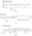
- the network device obtains a channel in Slot #0 and starts a downlink transmission to Slot #6.
- the network device may send a downlink transmission identification signal in Slot #2 and Slot #6 according to an indication of configuration information.
- the terminal first detects whether there is a downlink transmission identification signal in Slot #18, and finds that there is no downlink transmission identification signal in Slot #18.
- the terminal further performs detection in Slot #2 and finds that there is a downlink transmission identification signal.
- the terminal has buffered data of Slot #19, Slot #0, Slot #1, and Slot #2. If first indication information carried in the downlink transmission identification signal indicates that a starting position of COT is Slot #0. Then the terminal learns from the first indication information that a downlink transmission starts from Slot #0, so the terminal only performs PDCCH blind decoding on buffered data of Slot #0, Slot #1, and Slot #2, without performing PDCCH blind decoding on data of Slot19.
- a downlink transmission identification signal carries second indication information used for indicating whether there is downlink data in a detection period and the terminal detects the downlink transmission identification signal
- the terminal performs PDCCH blind decoding in the detection period in the case that the second indication information indicates that there is downlink data in the detection period; and the terminal skips performing the PDCCH blind decoding in the detection period in the case that the second indication information indicates that there is no downlink data in the detection period.
- the terminal skips performing the PDCCH blind decoding in the detection period and releases buffered data in the detection period in the case that the terminal buffers a received signal in the detection period to obtain the corresponding buffered data and the second indication information indicates that there is no downlink data in the detection period. That means that the network device may carry second indication information in a downlink transmission identification signal sent currently, to indicate whether there is data scheduling for a terminal in the previous detection period.
- An indication mode of the second indication information includes but is not limited to: using one indication bit to indicate whether there is data scheduling for a terminal in a detection period. For example, when a value of the indication bit is 1, it indicates that there is data scheduling for a terminal in a detection period, and when a value of the indication bit is 0, it indicates that there is no data scheduling for a terminal in a detection period; or vice versa.
- the terminal performs PDCCH blind decoding from a starting position of the detection period in the case that the terminal detects a downlink transmission identification signal, and the second indication information indicates that there is downlink data in the detection period; the terminal skips performing the PDCCH blind decoding in the detection period, and releases all buffered data in the case that the second indication information indicates that there is no downlink data in the detection period.
- the indication mode of the second indication information may also include an indication bitmap used for indicating whether there is downlink scheduling data on each time-domain transmission unit in the detection period. For example, in the case that a value of a bit in the indication bitmap is 1, it indicates that there is terminal scheduling data on a corresponding time-domain transmission unit; in the case that a value of a bit in the indication bitmap is 0, it indicates that there is no terminal scheduling data on a corresponding time-domain transmission unit; or vice versa.
- the step of performing PDCCH blind decoding on buffered data includes: on a time-domain transmission unit on which there is downlink data indicated by the indication bitmap, performing the PDCCH blind decoding on the time-domain transmission unit on which there is downlink data in the detection period.
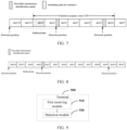
- the network device obtains a channel in Slot #0 and starts a downlink transmission to Slot #6.
- the network device may send a downlink transmission identification signal in Slot #2 and Slot #6 according to an indication of configuration information.
- a terminal 1 and a terminal 2 first detect separately whether there is a downlink transmission identification signal in Slot #18, and find that there is no downlink transmission identification signal in Slot #18.
- the terminal 1 and the terminal 2 further perform detection in Slot #2 and find that there is a downlink transmission identification signal.
- the downlink transmission identification signal in the embodiment of the present disclosure may not carry any information, and its function is only to remind the terminal that there is a downlink transmission.
- the terminal performs the PDCCH blind decoding from a starting position of buffered data after detecting the downlink transmission identification signal. That is, in the case that neither first indication information nor second indication information is detected, the PDCCH blind decoding is performed from the starting position of the buffered data.
- the network device obtains a channel in Slot #0 and starts a downlink transmission to Slot #6.
- the network device may send a downlink transmission identification signal in Slot #2 and Slot #6 according to an indication of configuration information.
- a terminal 3 first detects whether there is a downlink transmission identification signal in Slot #18, and finds that there is no downlink transmission identification signal in Slot #18.
- the terminal further performs detection in Slot #2 and finds that there is a downlink transmission identification signal.
- the terminal 3 has buffered data of Slot #19, Slot #0, Slot #1, and Slot #2. If the terminal 3 fails to detect first indication information and second indication information in the downlink transmission identification signal, the terminal 3 performs PDCCH blind decoding on buffered Slot # 19, Slot # 0 and Slot # 1.
- the second aspect perform processing subsequent to the first time-domain transmission unit.
- the terminal In the case of detecting the downlink transmission identification signal, the terminal triggers the PDCCH blind decoding on configured search space in the subsequent time-domain transmission unit.
- a condition for ending the PDCCH blind decoding includes but is not limited to the following modes: In the case that the terminal obtains a COT ending position of the network device, the terminal stops performing PDCCH blind decoding subsequent to the COT ending position, and resumes only detecting a downlink transmission identification signal. Specifically, subsequent to the COT ending position of the network device, the terminal stops performing PDCCH blind decoding, and detects a downlink transmission identification signal.
- the COT ending position is determined according to the downlink transmission identification signal.
- the terminal may start a counter (such as a PDCCH blind decoding counter) after starting the PDCCH blind decoding. After PDCCH blind decoding is performed on one time-domain transmission unit, the counter will add 1 or subtract 1. Specifically, the terminal starts the PDCCH blind decoding counter, where the PDCCH blind decoding counter is used to count a quantity of PDCCH blind decoding times; and when the PDCCH blind decoding counter reaches a preset threshold or returns to zero, the terminal stops performing the PDCCH blind decoding, and detect a downlink transmission identification signal.
- a counter such as a PDCCH blind decoding counter
- the network device obtains a channel in Slot #0 and starts a downlink transmission to Slot #6.
- the network device may send a downlink transmission identification signal in Slot #2 and Slot #6 according to an indication of configuration information.
- the terminal first detects whether there is a downlink transmission identification signal in Slot #18, and finds that there is no downlink transmission identification signal in Slot #18.
- the terminal further performs detection in Slot #2 and finds that there is a downlink transmission identification signal.
- the downlink transmission identification signal mentioned in the embodiment of the present disclosure may include one or more of a channel state information reference signal (Channel State Information Reference Signal, CSI-RS), a demodulation reference signal (De-Modulation Reference Signal, DMRS), a primary synchronization signal (Primary Synchronization Signal, PSS), a secondary synchronization signal (Secondary Synchronization Signal, SSS) and a group common physical downlink control channel (Group Common Physical Downlink Control Channel, GC-PDCCH), and another possible signal.
- CSI-RS Channel State Information Reference Signal
- DMRS demodulation reference signal
- PSS Primary Synchronization Signal
- SSS Secondary Synchronization Signal
- GC-PDCCH Group Common Physical Downlink Control Channel
- the indication information carried in the downlink transmission identification signal in the embodiment of the present disclosure may be downlink control information (Downlink Control Information, DCI), and different indication information may be implemented through different indicator fields in the DCI.
- DCI Downlink Control Information
- the terminal detects the downlink transmission identification signal on the first time-domain transmission unit in the detection period, and buffers the buffered data in the detection period.
- the buffered data in the detection period is buffered, and downlink data in the detection period is obtained by detecting the buffered data, so no downlink data will be lost due to missing the COT starting position.
- the first time-domain transmission unit is a detection position, and the detection position is located at a specific position in the detection period, or the first time-domain transmission unit is any position in the detection period.
- the terminal 900 further includes: a first processing module, configured to skip performing physical downlink control channel PDCCH blind decoding in the case that no downlink transmission identification signal is detected.
- the downlink transmission identification signal carries: first indication information used to indicate a starting position of channel occupancy time COT of the network device, and/or, second indication information used to indicate whether there is downlink data in a detection period.
- the terminal 900 further includes: a second processing module, configured to perform at least one of the following operations in the case that a downlink transmission identification signal is detected:
- the second indication information includes an indication bitmap used for indicating whether there is downlink scheduling data on each time-domain transmission unit in the detection period.
- the second processing module includes a first processing sub-module, configured to perform, on a time-domain transmission unit on which there is downlink data indicated by the indication bitmap, PDCCH blind decoding on the time-domain transmission unit on which there is downlink data in the detection period.
- the terminal 900 further includes: a third processing module, configured to perform PDCCH blind decoding on a time-domain transmission unit subsequent to the first time-domain transmission unit in the case that a downlink transmission identification signal is detected.
- a third processing module configured to perform PDCCH blind decoding on a time-domain transmission unit subsequent to the first time-domain transmission unit in the case that a downlink transmission identification signal is detected.
- the terminal 900 further includes: a fourth processing module, configured to stop performing PDCCH blind decoding subsequent to the COT ending position of the network device, and detect a downlink transmission identification signal.
- the ending position is determined according to the downlink transmission identification signal.
- the terminal 900 further includes:
- the terminal according to the embodiment of the present disclosure detects the downlink transmission identification signal on the first time-domain transmission unit in the detection period, and buffers the buffered data in the detection period.
- the buffered data in the detection period is buffered, and downlink data in the detection period is obtained by detecting the buffered data, so no downlink data will be lost due to missing the COT starting position.
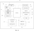
- FIG. 10 is a schematic structural diagram of hardware of a terminal for implementing the various embodiments of this disclosure.
- the terminal 100 includes, but is not limited to: components such as a radio frequency unit 101, a network module 102, an audio output unit 103, an input unit 104, a sensor 105, a display unit 106, a user input unit 107, an interface unit 108, a memory 109, a processor 1010, and a power supply 1011.
- the terminal may include more or fewer components than those shown in the figure, or some components may be combined, or there may be a different component arrangement.
- the terminal includes, but is not limited to, a mobile phone, a tablet computer, a notebook computer, a palmtop computer, a vehicle-mounted terminal, a wearable device, a pedometer, or the like.
- the processor 1010 is configured to detect a downlink transmission identification signal on a first time-domain transmission unit; and buffer buffered data of a detection period where the first time-domain transmission unit is located.
- the terminal detects the downlink transmission identification signal on the first time-domain transmission unit in the detection period, and buffers the buffered data in the detection period.
- the buffered data in the detection period is buffered, and downlink data in the detection period is obtained by detecting the buffered data, so no downlink data will be lost due to missing the COT starting position.
- the radio frequency unit 101 may be configured to receive and send information or receive and send a signal in a call process. Specifically, after receiving downlink data from a base station, the radio frequency unit 101 sends the downlink data to the processor 1010 for processing. In addition, the radio frequency unit 101 sends uplink data to the base station.
- the radio frequency unit 101 includes but is not limited to an antenna, at least one amplifier, a transceiver, a coupler, a low noise amplifier, a duplexer, and the like.
- the radio frequency unit 101 may communicate with a network and another device by using a wireless communications system.
- the terminal provides a user with wireless broadband Internet access by using the network module 102, for example, helping the user send and receive emails, browse web pages, and access streaming media.
- the audio output unit 103 may convert audio data received by the radio frequency unit 101 or the network module 102 or stored in the memory 109 into an audio signal and output the audio signal as a sound.
- the audio output unit 103 may further provide audio output (for example, call signal receiving sound or message receiving sound) related to a specific function performed by the terminal 100.
- the audio output unit 103 includes a loudspeaker, a buzzer, a receiver, and the like.
- the input unit 104 is configured to receive audio or video signals.
- the input unit 104 may include a graphics processing unit (Graphics Processing Unit, GPU) 1041 and a microphone 1042.
- the graphics processing unit 1041 processes image data of a static picture or a video obtained by an image capturing apparatus (for example, a camera) in a video capturing mode or an image capturing mode.
- a processed image frame can be displayed on the display unit 106.
- the image frame processed by the graphics processing unit 1041 may be stored in the memory 109 (or another storage medium) or sent via the radio frequency unit 101 or the network module 102.
- the microphone 1042 can receive sound, and can process such sound into audio data.
- the audio data obtained through processing may be converted, in a telephone call mode, into a format that can be sent to a mobile communications base station via the radio frequency unit 101 for output.
- the accelerometer sensor may be used for recognizing a terminal gesture (for example, horizontal and vertical screen switching, a related game, or magnetometer posture calibration), a function related to vibration recognition (for example, a pedometer or a strike), or the like.
- the sensor 105 may further include a fingerprint sensor, a pressure sensor, an iris sensor, a molecular sensor, a gyroscope, a barometer, a hygrometer, a thermometer, an infrared sensor, and the like. This is not described herein.
- the display unit 106 is configured to display information entered by a user or information provided for a user.
- the display unit 106 may include the display panel 1061, and the display panel 1061 may be configured in a form of a liquid crystal display (Liquid Crystal Display, LCD), an organic light-emitting diode (Organic Light-Emitting Diode, OLED), or the like.
- LCD Liquid Crystal Display
- OLED Organic Light-Emitting Diode
- the user input unit 107 may be configured to receive input numeral or character information, and generate key signal input related to user setting and functional control of the terminal.
- the user input unit 107 includes a touch panel 1071 and another input device 1072.
- the touch panel 1071 also known as a touchscreen, can collect a touch operation performed by a user on or near the touch panel 1071 (for example, an operation performed by the user on the touch panel 1071 or near the touch panel 1071 by using any suitable object or accessory such as a finger or a stylus).
- the touch panel 1071 may include two parts: a touch detection apparatus and a touch controller.
- the touch detection apparatus detects a touch position of the user, detects a signal brought by the touch operation, and sends the signal to the touch controller.
- the touch controller receives touch information from the touch detection apparatus, converts the touch information into touch point coordinates, sends the touch point coordinates to a processor 1010, and receives and executes a command sent by the processor 1010.
- the touch panel 1071 can be implemented in various types such as resistive, capacitive, infrared, and surface acoustic waves.
- the user input unit 107 may further include another input device 1072 in addition to the touch panel 1071.
- the another input device 1072 may include, but is not limited to, a physical keyboard, function keys (such as a volume control key and a switch key), a trackball, a mouse, and a joystick. Details are not described herein.
- the touch panel 1071 may cover the display panel 1061.
- the touch panel 1071 transmits the touch operation to the processor 1010 to determine a type of a touch event, and then the processor 1010 provides corresponding visual output on the display panel 1061 based on the type of the touch event.
- the touch panel 1071 and the display panel 1061 are used as two independent components to implement input and output functions of the terminal.
- the touch panel 1071 and the display panel 1061 may be integrated to implement the input and output functions of the terminal. This is not specifically limited herein.
- the interface unit 108 is an interface connecting an external apparatus to the terminal 100.
- the external apparatus may include a wired or wireless headset port, an external power supply (or a battery charger) port, a wired or wireless data port, a memory card port, a port for connecting an apparatus having an identification module, an audio input/output (I/O) port, a video I/O port, a headset port, and the like.
- the interface unit 108 may be configured to receive an input (for example, data information or power) from an external apparatus and transmit the received input to one or more elements in the terminal 100, or transmit data between the terminal 100 and the external apparatus.
- the memory 109 may be configured to store software programs and various data.
- the memory 109 may mainly include a program storage area and a data storage area.
- the program storage area may store an operating system, an application required by at least one function (for example, an audio playing function and an image playing function), and the like.
- the data storage area may store data (for example, audio data and an address book) created according to use of the mobile phone.
- the memory 109 may include a high speed random access memory, and may further include a non-volatile memory, for example, at least one magnetic disk memory device, a flash memory device, or another volatile solid state memory device.
- the processor 1010 is a control center of the terminal, and connects all parts of the entire terminal by using various interfaces and lines. By running or executing a software program and/or a module stored in the memory 109 and invoking data stored in the memory 109, the processor 1010 performs various functions of the terminal and data processing, to perform overall monitoring on the terminal.
- the processor 1010 can include one or more processing units.
- the processor 1010 can be integrated with an application processor and a modem processor.
- the application processor mainly processes the operating system, the user interface, applications, etc.
- the modem processor mainly processes wireless communication. It may be understood that the modem processor may not be integrated into the processor 1010.
- the terminal 100 may further include the power supply 1011 (such as a battery) that supplies power to each component.
- the power supply 1011 may be logically connected to the processor 1010 by using a power management system, so as to implement functions such as charging, discharging, and power consumption management by using the power management system.
- the terminal 100 includes some function modules not shown, and details are not described herein.
- an embodiment of the present disclosure further provides a terminal, including a processor 1010, a memory 109, and a computer program that is stored in the memory 109 and that can run on the processor 1010.
- a terminal including a processor 1010, a memory 109, and a computer program that is stored in the memory 109 and that can run on the processor 1010.
- the terminal may be a wireless terminal or a wired terminal.
- the wireless terminal may be a device providing voice and/or other service data connectivity to a user, a handheld device with a wireless connection function, or another processing device connected to a wireless modem.
- the wireless terminal may communicate with one or more core networks through a radio access network (Radio Access Network, RAN).
- Radio Access Network Radio Access Network
- the wireless terminal may be a mobile terminal, such as a mobile phone (also referred to as a "cellular" phone) and a computer with a mobile terminal, for example, may be a portable, pocket-sized, handheld, computer built-in, or in-vehicle mobile apparatus, which exchanges voice and/or data with the radio access network.
- the wireless terminal may be a device such as a personal communication service (Personal Communication Service, PCS) phone, a cordless telephone set, a session initiation protocol (Session Initiation Protocol, SIP) phone, a wireless local loop (Wireless Local Loop, WLL) station, or a personal digital assistant (Personal Digital Assistant, PDA).
- PCS Personal Communication Service
- SIP Session Initiation Protocol
- WLL Wireless Local Loop
- PDA Personal Digital Assistant
- the wireless terminal may also be referred to as a system, a subscriber unit (Subscriber Unit), a subscriber station (Subscriber Station), a mobile station (Mobile Station), a mobile (Mobile), a remote station (Remote Station), a remote terminal (Remote Terminal), an access terminal (Access Terminal), a user terminal (User Terminal), a user agent (User Agent), or a user device (User Device or User Equipment), which is not limited herein.
- An embodiment of the present disclosure further provides a computer-readable storage medium, with a computer program stored thereon, where when the computer program is executed by a processor, the processes of the embodiment of the foregoing information transmission method are implemented, with the same technical effects achieved. To avoid repetition, details are not described again herein.
- the computer readable storage medium may be a read-only memory (Read-Only Memory, ROM), a random access memory (Random Access Memory, RAM), a magnetic disk, a compact disc, or the like.
- an information transmission method is applied to a network device side, and includes the following steps: Step 111.
- Configure configuration information of a downlink transmission identification signal for a terminal where the configuration information includes: a detection period and/or a detection position.
- the configuration information includes: a detection period and/or a detection position, where the detection position is located at a specific position in the detection period, or the detection position is located at any position in the detection period.
- the configuration information configured by the network device may include a detection period T and a detection position of a downlink transmission identification signal, that is, the network device informs the terminal of an absolute candidate position where the downlink transmission identification signal may appear. In this mode, as the detection position is known, the terminal only needs to detect the downlink transmission identification signal at the detection position.
- Step 112. Send the downlink transmission identification signal according to a detection period and/or a detection position indicated by the configuration information in the case that downlink data is scheduled for the terminal.
- the downlink data scheduled at one time corresponds to one or more downlink transmission identification signals, and a specific quantity correspondence may be determined according to an attribute of the downlink data. For example, when downlink data of a certain scheduling is of high importance, multiple downlink transmission identification signals may be dispensed for this scheduling.
- the network device may carry indication information related to a downlink transmission in a downlink transmission identification signal.
- the downlink transmission identification signal carries: first indication information used to indicate a starting position of channel occupancy time COT of the network device, and/or, second indication information used to indicate whether there is downlink data in a detection period.
- the downlink transmission identification signal may also carry third indication information used for indicating an ending position of channel occupancy time COT of the network device.
- the indication mode of the second indication information includes but is not limited to: using one indication bit to indicate whether there is data scheduling for a terminal in buffered data. For example, when a value of the indication bit is 1, it indicates that there is data scheduling for a terminal in buffered data, and when a value of the indication bit is 0, it indicates that there is no data scheduling for a terminal in buffered data; or vice versa.
- the indication mode of the second indication information may also include an indication bitmap used for indicating whether there is downlink scheduling data on each time-domain transmission unit in the detection period. For example, in the case that a value of a bit in the indication bitmap is 1, it indicates that there is terminal scheduling data on a corresponding time-domain transmission unit; in the case that a value of a bit in the indication bitmap is 0, it indicates that there is no terminal scheduling data on a corresponding time-domain transmission unit; or vice versa.
- the downlink transmission identification signal mentioned in the embodiment of the present disclosure may include one or more of various possible signals such as CSI-RS, DMRS, PSS, SSS and GC-PDCCH.
- the indication information carried in the downlink transmission identification signal may be DCI, and different indication information may be implemented through different indicator fields in DCI.
- the network device may send downlink transmission identification information on one time-domain transmission unit in a detection period without sending downlink transmission identification information on every time-domain transmission unit, thus lowering system overhead and improving system throughput.
- a network device 1200 can implement the configuration information of the downlink transmission identification signal configured for the terminal in the foregoing embodiment, where the configuration information includes: a detection period and/or a detection position.
- the downlink transmission identification signal is sent according to the detection period and/or detection position indicated by the configuration information.
- the network device 1200 specifically includes the following function modules:
- the detection position is located at a specific position in the detection period, or the detection position is located at any position in the detection period.
- the downlink transmission identification signal carries: first indication information used to indicate a starting position of channel occupancy time COT of the network device, and/or, second indication information used to indicate whether there is downlink data in a detection period.
- the second indication information includes an indication bitmap used for indicating whether there is downlink scheduling data on each time-domain transmission unit in the detection period.
- the network device may send downlink transmission identification information on one time-domain transmission unit in a detection period without sending downlink transmission identification information on every time-domain transmission unit, thus lowering system overhead and improving system throughput.
- modules of the network device and the terminal are merely logical function division, and in actual implementation, the modules may be all or partially integrated into one physical entity, or may be physically separated.
- these modules may all be implemented in the form of software being invoked by processing elements; or may all be implemented in the form of hardware; or some of the modules may be implemented in the form of software being invoked by processing elements, and some of the modules may be implemented in the form of hardware.
- the determining module may be a separately disposed processing element, or may be integrated into a chip of the foregoing apparatus for implementation.
- the determining module may also be stored in the memory of the foregoing apparatus in the form of program code, and a processing element of the foregoing apparatus invokes the program code and performs the functions of the foregoing determining module.
- the implementation of another module is similar thereto.
- all or some of these modules may be integrated together or implemented independently.
- the processing element herein may be an integrated circuit having a signal processing capability. During implementation, the steps of the foregoing method or the foregoing modules can be completed by hardware integrated logic circuits in the processor element or instructions in the form of software.
- the modules may be configured as one or more integrated circuits for implementing the foregoing method, for example, one or more application specific integrated circuits (Application Specific Integrated Circuit, ASIC), one or more microprocessors (digital signal processor, DSP), or one or more field programmable gate arrays (Field Programmable Gate Array, FPGA).
- ASIC Application Specific Integrated Circuit
- DSP digital signal processor
- FPGA Field Programmable Gate Array
- the processing element may be a general-purpose processor, for example, a central processing unit (Central Processing Unit, CPU) or another processor that can invoke program code.
- these modules may be integrated together, and implemented in a form of a system-on-a-chip (system-on-a-chip, SOC).
- an embodiment of the present disclosure further provides a network device, including a processor, a memory, and a computer program stored in the memory and capable of running on the processor, where steps of the foregoing information transmission method are implemented in the case that the computer program is executed by the processor.
- An embodiment of the present invention further provides a computer-readable storage medium, with a computer program stored thereon, where steps of the foregoing information transmission method are implemented in the case that the computer program is executed by a processor.
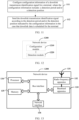
- a network device 1300 includes: an antenna 131, a radio frequency apparatus 132, and a baseband apparatus 133.
- the antenna 131 is connected to the radio frequency apparatus 132.
- the radio frequency apparatus 132 receives information through the antenna 131, and sends the received information to the baseband apparatus 133 for processing.
- the baseband apparatus 133 processes information to be sent and sends the information to the radio frequency apparatus 132, and the radio frequency apparatus 132 processes the received information and then sends the information through the antenna 131.
- the foregoing band processing apparatus may be located in the baseband apparatus 133, and the method performed by the network device in the foregoing embodiment may be implemented in the baseband apparatus 133.
- the baseband apparatus 133 includes a processor 134 and a memory 135.
- the baseband apparatus 133 may include, for example, at least one baseband board, and a plurality of chips are arranged on the baseband board. As shown in FIG. 13 , one of the chips is, for example, the processor 134, which is connected to the memory 135, to invoke a program in the memory 135, so as to perform the operations of the network device shown in the foregoing method embodiment.
- the baseband apparatus 133 may further include a network interface 136, configured to exchange information with the radio frequency apparatus 132.
- the interface is a common public radio interface (common public radio interface, CPRI).
- the processor herein may be a single processor, or may be a collective term for a plurality of processing elements.
- the processor may be a CPU or an ASIC, or may be one or more integrated circuits that are configured to implement the foregoing method performed by the network device, for example, may be one or more microprocessors DSPs, or one or more field programmable gate arrays FPGAs.
- the storage element may be one memory or a collective term for a plurality of storage elements.
- the memory 135 may be a volatile memory or a non-volatile memory, or may include both a volatile memory and a non-volatile memory.
- the non-volatile memory may be a read-only memory (Read-only Memory, ROM), a programmable read-only memory (Programmable ROM, PROM), an erasable programmable read-only memory (Erasable PROM, EPROM), an electrically erasable programmable read-only memory (Electrically EPROM, EEPROM), or a flash memory.
- the volatile memory may be a random access memory (Random Access Memory, RAM), used as an external cache.
- RAMs may be used, for example, a static random access memory (Static RAM, SRAM), a dynamic random access memory (Dynamic RAM, DRAM), a synchronous dynamic random access memory (Synchronous DRAM, SDRAM), a double data rate synchronous dynamic random access memory (Double Data Rate SDRAM, DDRSDRAM), an enhanced synchronous dynamic random access memory (Enhanced SDRAM, ESDRAM), a synchlink dynamic random access memory (Synchlink DRAM, SLDRAM), and a direct rambus random access memory (Direct Rambus RAM, DRRAM).
- Static RAM Static RAM
- DRAM dynamic random access memory
- DRAM synchronous dynamic random access memory
- SDRAM double data rate synchronous dynamic random access memory
- Double Data Rate SDRAM Double Data Rate SDRAM
- ESDRAM enhanced synchronous dynamic random access memory
- Synchlink DRAM synchlink dynamic random access memory
- SLDRAM direct rambus random access memory
- Direct Rambus RAM Direct Rambus RAM
- the network device in this embodiment of this disclosure further includes a computer program stored in the memory 135 and executable on the processor 134, and the processor 134 invokes the computer program in the memory 135 to perform the method performed by the modules shown in FIG. 12 .
- the computer program when called by the processor 134, it may be used to perform: sending a downlink transmission identification signal on a time-domain transmission unit in a detection period in the case that downlink data is scheduled for a terminal.
- the network device may send downlink transmission identification information on one time-domain transmission unit in a detection period without sending downlink transmission identification information on every time-domain transmission unit, thus lowering system overhead and improving system throughput.
- the disclosed apparatus and method may be implemented in other manners.
- the described apparatus embodiment is merely an example.
- the unit division is merely logical function division and may be other division in actual implementation.
- a plurality of units or components may be combined or integrated into another system, or some features may be ignored or not performed.
- the displayed or discussed mutual couplings or direct couplings or communication connections may be implemented by using some interfaces.
- the indirect couplings or communication connections between the apparatuses or units may be implemented in electronic, mechanical, or other forms.
- the units described as separate components may or may not be physically separated, and the components displayed as units may or may not be physical units, and may be located in one place or may be distributed on a plurality of network units. Some or all of the units may be selected based on actual requirements to achieve the objectives of the solutions of the embodiments.
- function units in the embodiments of the present disclosure may be integrated into one processing unit, or each of the units may exist alone physically, or two or more units are integrated into one unit.
- the function may be stored in a computer-readable storage medium.
- the computer software product is stored in a storage medium, and includes several instructions for instructing a computer device (which may be a personal computer, a server, a network device, or the like) to perform all or some of the steps of the methods described in the embodiments of the present disclosure.
- the storage medium includes various mediums, such as a USB flash disk, a removable hard disk, a ROM, a RAM, a magnetic disk, or an optical disc, that can store program code.
- the objective of the present disclosure may also be achieved by running a program or a set of programs on any computing apparatus.
- the computing apparatus may be a well-known general-purpose apparatus. Therefore, the objective of the present disclosure may also be achieved only by providing a program product including program code for implementing the method or the apparatus.
- a program product also constitutes this disclosure
- a storage medium storing such a program product also constitutes this disclosure.
- the storage medium may be any well-known storage medium or any storage medium to be developed in the future.
- the components or steps may be divided and/or recombined.
- the steps for performing the foregoing series of processing may be performed naturally in chronological order according to a described sequence, but do not necessarily need to be performed in chronological order, and some steps may be performed in parallel or independently.
Landscapes
- Engineering & Computer Science (AREA)
- Signal Processing (AREA)
- Computer Networks & Wireless Communication (AREA)
- Quality & Reliability (AREA)
- Mobile Radio Communication Systems (AREA)
Claims (15)
- Procédé de transmission d'informations, appliqué à un terminal, comprenant :
recevoir (31) des informations de configuration d'un signal d'identification de transmission de liaison descendante provenant d'un dispositif de réseau, dans lequel les informations de configuration comprennent :une période de détection et/ou une position de détection ;détecter (32) le signal d'identification de transmission de liaison descendante sur une première unité de transmission dans le domaine temporel d'une bande sans licence selon la période de détection et/ou une position de détection indiquée(s) par les informations de configuration,omettre d'effectuer le décodage aveugle du canal de commande de liaison descendante physique, PDCCH, dans le cas où aucun signal d'identification de transmission de liaison descendante n'est détecté ; eteffectuer le décodage aveugle du PDCCH sur une unité de transmission dans le domaine temporel suite à la première unité de transmission dans le domaine temporel dans le cas où le signal d'identification de transmission de liaison descendante est détecté. - Procédé de transmission d'informations selon la revendication 1, dans lequel le signal d'identification de transmission de liaison descendante transporte : des premières informations d'indication utilisées pour indiquer une position de départ du temps d'occupation du canal, COT, d'un dispositif de réseau, et/ou des deuxièmes informations d'indication utilisées pour indiquer s'il y a des données de liaison descendante dans la période de détection.
- Terminal, comprenant :un premier module de réception (910), configuré pour recevoir des informations de configuration d'un signal d'identification de transmission de liaison descendante d'un dispositif de réseau, dans lequel les informations de configuration comprennent : une période de détection et/ou une position de détection ;un module de détection (920), configuré pour détecter un signal d'identification de transmission de liaison descendante sur une première unité de transmission dans le domaine temporel d'une bande sans licence selon une période de détection et/ou une position de détection indiquée(s) par les informations de configuration ;un premier module de traitement, configuré pour omettre d'effectuer le décodage aveugle du canal de commande de liaison descendante physique, PDCCH, dans le cas où aucun signal d'identification de transmission de liaison descendante n'est détecté ; etun troisième module de traitement, configuré pour effectuer le décodage aveugle du PDCCH sur une unité de transmission dans le domaine temporel suite à la première unité de transmission dans le domaine temporel dans le cas où le signal d'identification de transmission de liaison descendante est détecté.
- Terminal selon la revendication 3, dans lequel la première unité de transmission dans le domaine temporel est la position de détection, et la position de détection est située à une position spécifique dans la période de détection, ou la première unité de transmission dans le domaine temporel est n'importe quelle position dans la période de détection.
- Terminal selon la revendication 3, dans lequel le signal d'identification de transmission de liaison descendante transporte : des premières informations d'indication utilisées pour indiquer une position de départ du temps d'occupation du canal, COT, d'un dispositif de réseau, et/ou des deuxièmes informations d'indication utilisées pour indiquer s'il y a des données de liaison descendante dans la période de détection.
- Terminal selon la revendication 5, comprenant de plus :
un deuxième module de traitement, configuré pour effectuer au moins l'une des opérations suivantes dans le cas où le signal d'identification de transmission de liaison descendante est détecté :effectuer un décodage aveugle du PDCCH dans la période de détection à partir d'une position de départ indiquée par les premières informations d'indication ;effectuer un décodage aveugle du PDCCH dans la période de détection dans le cas où les deuxièmes informations d'indication indiquent qu'il y a des données de liaison descendante dans la période de détection ; eteffectuer un décodage aveugle du PDCCH à partir d'une position de départ de la période de détection dans le cas où ni les premières informations d'indication ni les deuxièmes informations d'indication ne sont détectées. - Terminal selon la revendication 6, dans lequel les deuxièmes informations d'indication comprennent un mode point d'indication utilisé pour indiquer s'il y a des données de programmation de liaison descendante sur chaque unité de transmission dans le domaine temporel dans la période de détection ;
dans lequel le deuxième module de traitement comprend :
un premier sous-module de traitement, configuré pour effectuer, sur une unité de transmission dans le domaine temporel dans lequel il y a des données de liaison descendante indiquées par le mode point d'indication, un décodage aveugle du PDCCH sur une unité de transmission dans le domaine temporel où il y a des données de liaison descendante dans la période de détection. - Terminal selon la revendication 3, comprenant de plus :
un quatrième module de traitement, configuré pour arrêter d'effectuer le décodage aveugle du PDCCH suite à la position de fin du COT du dispositif de réseau, et détecter un signal d'identification de transmission de liaison descendante. - Terminal selon la revendication 8, dans lequel la position finale est déterminée selon le signal d'identification de transmission de liaison descendante.
- Terminal selon la revendication 3, comprenant de plus :un module de démarrage, configuré pour démarrer un compteur de décodage aveugle de PDCCH, dans lequel le compteur de décodage aveugle de PDCCH est configuré pour compter une quantité de temps de décodage aveugle de PDCCH ;un cinquième module de traitement, configuré pour arrêter le décodage aveugle de PDCCH et détecter un signal d'identification de transmission de liaison descendante dans le cas où le compteur de décodage aveugle de PDCCH atteint un seuil prédéfini ou revient à zéro.
- Dispositif de réseau, appliqué à une transmission de bande sans licence, comprenant :un module de configuration (1210), configuré pour configurer des informations de configuration d'un signal d'identification de transmission de liaison descendante pour un terminal, dans lequel les informations de configuration comprennent : une période de détection et/ou une position de détection ; etun module d'envoi (1220), configuré pour envoyer le signal d'identification de transmission de liaison descendante selon la période de détection et/ou la position de détection indiquée(s) par les informations de configuration dans le cas où des données de liaison descendante sont programmées pour le terminal,dans lequel le signal d'identification de transmission de liaison descendante est utilisé pour : indiquer au terminal d'effectuer un décodage aveugle du canal de commande de liaison descendante physique, PDCCH, sur une unité de transmission dans le domaine temporel suite à une première unité de transmission dans le domaine temporel, dans le cas où le signal d'identification de transmission de liaison descendante est détecté,et indiquer au terminal d'omettre d'effectuer le décodage aveugle du PDCCH dans le cas où aucun signal d'identification de transmission de liaison descendante n'est détecté.
- Dispositif de réseau selon la revendication 11, dans lequel la position de détection est située à une position spécifique dans la période de détection, ou la position de détection est située à n'importe quelle position dans la période de détection.
- Dispositif de réseau selon la revendication 11, dans lequel le signal d'identification de transmission de liaison descendante transporte : des premières informations d'indication utilisées pour indiquer une position de départ du temps d'occupation du canal, COT, d'un dispositif de réseau, et/ou des deuxièmes informations d'indication utilisées pour indiquer s'il y a des données de liaison descendante dans la période de détection.
- Dispositif de réseau selon la revendication 13, dans lequel les deuxièmes informations d'indication comprennent un mode point d'indication utilisé pour indiquer s'il y a des données de programmation de liaison descendante sur chaque unité de transmission dans le domaine temporel dans la période de détection.
- Procédé de transmission d'informations, appliqué à un côté de dispositif de réseau et sur une transmission de bande sans licence, comprenant :configurer (111) des informations de configuration d'un signal d'identification de transmission de liaison descendante pour un terminal, dans lequel les informations de configuration comprennent : une période de détection et/ou une position de détection ; etenvoyer (112) le signal d'identification de transmission de liaison descendante selon la période de détection et/ou la position de détection indiquée(s) par les informations de configuration dans le cas où des données de liaison descendante sont programmées pour un terminal,dans lequel le signal d'identification de transmission de liaison descendante est utilisé pour : indiquer au terminal d'effectuer un décodage aveugle du canal de commande de liaison descendante physique, PDCCH, sur une unité de transmission dans le domaine temporel suite à une première unité de transmission dans le domaine temporel, dans le cas où le signal d'identification de transmission de liaison descendante est détecté,et indiquer au terminal d'omettre d'effectuer le décodage aveugle du PDCCH dans le cas où aucun signal d'identification de la transmission de liaison descendante n'est détecté.
Applications Claiming Priority (2)
| Application Number | Priority Date | Filing Date | Title |
|---|---|---|---|
| CN201811626877.6A CN111278026B (zh) | 2018-12-28 | 2018-12-28 | 一种信息传输方法、终端及网络设备 |
| PCT/CN2019/106942 WO2020134222A1 (fr) | 2018-12-28 | 2019-09-20 | Procédé de transmission d'informations, terminal et dispositif réseau |
Publications (3)
| Publication Number | Publication Date |
|---|---|
| EP3905751A1 EP3905751A1 (fr) | 2021-11-03 |
| EP3905751A4 EP3905751A4 (fr) | 2022-03-09 |
| EP3905751B1 true EP3905751B1 (fr) | 2024-09-11 |
Family
ID=71003264
Family Applications (1)
| Application Number | Title | Priority Date | Filing Date |
|---|---|---|---|
| EP19905365.3A Active EP3905751B1 (fr) | 2018-12-28 | 2019-09-20 | Procédé de transmission d'informations, terminal et dispositif réseau |
Country Status (6)
| Country | Link |
|---|---|
| US (1) | US12052579B2 (fr) |
| EP (1) | EP3905751B1 (fr) |
| KR (1) | KR102650921B1 (fr) |
| CN (1) | CN111278026B (fr) |
| ES (1) | ES2989894T3 (fr) |
| WO (1) | WO2020134222A1 (fr) |
Families Citing this family (4)
| Publication number | Priority date | Publication date | Assignee | Title |
|---|---|---|---|---|
| US10477475B2 (en) * | 2017-03-23 | 2019-11-12 | Apple Inc. | Control indicator for power saving in a mobile wireless communication device |
| CN117295180B (zh) * | 2019-11-08 | 2024-11-05 | Oppo广东移动通信有限公司 | 非授权频谱上的数据传输方法、装置、设备及存储介质 |
| EP4059307A4 (fr) * | 2019-11-15 | 2023-11-01 | Qualcomm Incorporated | Techniques destinées à un signal de réveil de canal de commande |
| CN113853013B (zh) * | 2020-06-28 | 2025-10-03 | 华为技术有限公司 | 一种干扰协调方法、装置和系统 |
Family Cites Families (11)
| Publication number | Priority date | Publication date | Assignee | Title |
|---|---|---|---|---|
| CN101299871B (zh) * | 2007-04-30 | 2012-07-25 | 电信科学技术研究院 | 发送上行探测导频的方法及系统、基站和终端 |
| CN102170703A (zh) * | 2011-05-11 | 2011-08-31 | 电信科学技术研究院 | 一种物理下行控制信道上的信息收发方法及设备 |
| CN105992376B (zh) * | 2015-02-13 | 2019-01-22 | 中兴通讯股份有限公司 | 一种实现业务调度的方法、系统、基站及用户设备 |
| CN109274459A (zh) | 2016-05-13 | 2019-01-25 | 华为技术有限公司 | 传输下行控制信息的方法和装置 |
| CN107666713B (zh) * | 2016-07-27 | 2021-03-23 | 普天信息技术有限公司 | 一种sTTI中sPDCCH的传输方法以及装置 |
| CN109565386A (zh) * | 2016-09-29 | 2019-04-02 | 华为技术有限公司 | 通信方法、终端设备和基站 |
| US11240835B2 (en) * | 2017-01-17 | 2022-02-01 | Huawei Technologies Co., Ltd. | System and method for co-existence of low-latency and latency-tolerant communication resources |
| CN108737040B (zh) * | 2017-04-14 | 2020-12-25 | 华为技术有限公司 | 传输方法、终端和网络设备 |
| WO2019143164A1 (fr) * | 2018-01-21 | 2019-07-25 | 엘지전자 주식회사 | Procédé d'émission ou de réception de signal dans un système de communication sans fil et appareil à cet effet |
| WO2019194580A1 (fr) * | 2018-04-04 | 2019-10-10 | 엘지전자 주식회사 | Procédé de réception d'un signal de référence par un terminal dans un système de communications sans fil, et terminal utilisant le procédé |
| US11153872B2 (en) * | 2018-07-31 | 2021-10-19 | Asustek Computer Inc. | Method and apparatus for indicating slot format of an unlicensed cell in a wireless communication system |
-
2018
- 2018-12-28 CN CN201811626877.6A patent/CN111278026B/zh active Active
-
2019
- 2019-09-20 KR KR1020217023289A patent/KR102650921B1/ko active Active
- 2019-09-20 WO PCT/CN2019/106942 patent/WO2020134222A1/fr not_active Ceased
- 2019-09-20 ES ES19905365T patent/ES2989894T3/es active Active
- 2019-09-20 EP EP19905365.3A patent/EP3905751B1/fr active Active
-
2021
- 2021-06-28 US US17/360,397 patent/US12052579B2/en active Active
Also Published As
| Publication number | Publication date |
|---|---|
| US20210329470A1 (en) | 2021-10-21 |
| EP3905751A1 (fr) | 2021-11-03 |
| CN111278026A (zh) | 2020-06-12 |
| WO2020134222A1 (fr) | 2020-07-02 |
| EP3905751A4 (fr) | 2022-03-09 |
| KR20210108437A (ko) | 2021-09-02 |
| US12052579B2 (en) | 2024-07-30 |
| KR102650921B1 (ko) | 2024-03-22 |
| CN111278026B (zh) | 2022-01-25 |
| ES2989894T3 (es) | 2024-11-28 |
Similar Documents
| Publication | Publication Date | Title |
|---|---|---|
| JP7369782B2 (ja) | ハイブリッド自動再送要求harqフィードバック方法、端末及びネットワーク機器 | |
| US11601902B2 (en) | Synchronization signal block transmission method, network device, and terminal | |
| US12250730B2 (en) | Random access method and terminal | |
| US11463215B2 (en) | Transmission resource indication method, network device, and terminal | |
| AU2019267977B2 (en) | Quasi co-location configuration method, terminal, and network device | |
| US12160889B2 (en) | Unlicensed band information transmission method, terminal and network device | |
| EP3843472B1 (fr) | Procédé de transmission d'informations de liaison montante et terminal | |
| US12052579B2 (en) | Information transmission method, terminal and network device | |
| US12108259B2 (en) | Information transmission method in unlicensed band, terminal, and network device | |
| WO2020057317A1 (fr) | Procédé de transmission de signal d'instruction de transmission, dispositif réseau et terminal | |
| CN110875808B (zh) | 系统信息传输方法、网络设备及终端 | |
| CN110545582B (zh) | 一种随机接入资源确定方法及终端 | |
| CN110611954B (zh) | 一种带宽部分的处理方法、终端及网络设备 | |
| WO2021088783A1 (fr) | Procédé et appareil permettant de détecter un canal de commande de liaison descendante physique | |
| WO2020151706A1 (fr) | Procédé de transmission d'accès aléatoire, et terminal | |
| EP4057690A1 (fr) | Procédé de transfert intercellulaire, procédé de configuration, terminal et dispositif de réseau | |
| US12185117B2 (en) | Unlicensed band information transmission method, terminal and network device | |
| HK40072715A (en) | Handover method, configuration method, terminal, and network device | |
| HK40072715B (en) | Handover method, configuration method, terminal, and network device |
Legal Events
| Date | Code | Title | Description |
|---|---|---|---|
| STAA | Information on the status of an ep patent application or granted ep patent |
Free format text: STATUS: THE INTERNATIONAL PUBLICATION HAS BEEN MADE |
|
| PUAI | Public reference made under article 153(3) epc to a published international application that has entered the european phase |
Free format text: ORIGINAL CODE: 0009012 |
|
| STAA | Information on the status of an ep patent application or granted ep patent |
Free format text: STATUS: REQUEST FOR EXAMINATION WAS MADE |
|
| 17P | Request for examination filed |
Effective date: 20210706 |
|
| AK | Designated contracting states |
Kind code of ref document: A1 Designated state(s): AL AT BE BG CH CY CZ DE DK EE ES FI FR GB GR HR HU IE IS IT LI LT LU LV MC MK MT NL NO PL PT RO RS SE SI SK SM TR |
|
| A4 | Supplementary search report drawn up and despatched |
Effective date: 20220203 |
|
| RIC1 | Information provided on ipc code assigned before grant |
Ipc: H04L 1/00 20060101ALI20220128BHEP Ipc: H04W 72/04 20090101ALI20220128BHEP Ipc: H04W 24/02 20090101AFI20220128BHEP |
|
| DAV | Request for validation of the european patent (deleted) | ||
| DAX | Request for extension of the european patent (deleted) | ||
| REG | Reference to a national code |
Ref legal event code: R079 Ipc: H04W0024080000 Ref country code: DE Ref legal event code: R079 Ref document number: 602019058929 Country of ref document: DE Free format text: PREVIOUS MAIN CLASS: H04W0024020000 Ipc: H04W0024080000 |
|
| RIC1 | Information provided on ipc code assigned before grant |
Ipc: H04W 74/0808 20240101ALN20240313BHEP Ipc: H04W 24/02 20090101ALN20240313BHEP Ipc: H04L 1/00 20060101ALI20240313BHEP Ipc: H04W 24/08 20090101AFI20240313BHEP |
|
| GRAP | Despatch of communication of intention to grant a patent |
Free format text: ORIGINAL CODE: EPIDOSNIGR1 |
|
| STAA | Information on the status of an ep patent application or granted ep patent |
Free format text: STATUS: GRANT OF PATENT IS INTENDED |
|
| INTG | Intention to grant announced |
Effective date: 20240422 |
|
| GRAS | Grant fee paid |
Free format text: ORIGINAL CODE: EPIDOSNIGR3 |
|
| GRAA | (expected) grant |
Free format text: ORIGINAL CODE: 0009210 |
|
| STAA | Information on the status of an ep patent application or granted ep patent |
Free format text: STATUS: THE PATENT HAS BEEN GRANTED |
|
| AK | Designated contracting states |
Kind code of ref document: B1 Designated state(s): AL AT BE BG CH CY CZ DE DK EE ES FI FR GB GR HR HU IE IS IT LI LT LU LV MC MK MT NL NO PL PT RO RS SE SI SK SM TR |
|
| REG | Reference to a national code |
Ref country code: GB Ref legal event code: FG4D |
|
| REG | Reference to a national code |
Ref country code: CH Ref legal event code: EP |
|
| REG | Reference to a national code |
Ref country code: DE Ref legal event code: R096 Ref document number: 602019058929 Country of ref document: DE |
|
| REG | Reference to a national code |
Ref country code: IE Ref legal event code: FG4D |
|
| REG | Reference to a national code |
Ref country code: NL Ref legal event code: FP |
|
| REG | Reference to a national code |
Ref country code: ES Ref legal event code: FG2A Ref document number: 2989894 Country of ref document: ES Kind code of ref document: T3 Effective date: 20241128 |
|
| REG | Reference to a national code |
Ref country code: LT Ref legal event code: MG9D |
|
| PG25 | Lapsed in a contracting state [announced via postgrant information from national office to epo] |
Ref country code: NO Free format text: LAPSE BECAUSE OF FAILURE TO SUBMIT A TRANSLATION OF THE DESCRIPTION OR TO PAY THE FEE WITHIN THE PRESCRIBED TIME-LIMIT Effective date: 20241211 |
|
| PG25 | Lapsed in a contracting state [announced via postgrant information from national office to epo] |
Ref country code: GR Free format text: LAPSE BECAUSE OF FAILURE TO SUBMIT A TRANSLATION OF THE DESCRIPTION OR TO PAY THE FEE WITHIN THE PRESCRIBED TIME-LIMIT Effective date: 20241212 Ref country code: FI Free format text: LAPSE BECAUSE OF FAILURE TO SUBMIT A TRANSLATION OF THE DESCRIPTION OR TO PAY THE FEE WITHIN THE PRESCRIBED TIME-LIMIT Effective date: 20240911 |
|
| PG25 | Lapsed in a contracting state [announced via postgrant information from national office to epo] |
Ref country code: BG Free format text: LAPSE BECAUSE OF FAILURE TO SUBMIT A TRANSLATION OF THE DESCRIPTION OR TO PAY THE FEE WITHIN THE PRESCRIBED TIME-LIMIT Effective date: 20240911 |
|
| PG25 | Lapsed in a contracting state [announced via postgrant information from national office to epo] |
Ref country code: LV Free format text: LAPSE BECAUSE OF FAILURE TO SUBMIT A TRANSLATION OF THE DESCRIPTION OR TO PAY THE FEE WITHIN THE PRESCRIBED TIME-LIMIT Effective date: 20240911 |
|
| PG25 | Lapsed in a contracting state [announced via postgrant information from national office to epo] |
Ref country code: HR Free format text: LAPSE BECAUSE OF FAILURE TO SUBMIT A TRANSLATION OF THE DESCRIPTION OR TO PAY THE FEE WITHIN THE PRESCRIBED TIME-LIMIT Effective date: 20240911 |
|
| PG25 | Lapsed in a contracting state [announced via postgrant information from national office to epo] |
Ref country code: RS Free format text: LAPSE BECAUSE OF FAILURE TO SUBMIT A TRANSLATION OF THE DESCRIPTION OR TO PAY THE FEE WITHIN THE PRESCRIBED TIME-LIMIT Effective date: 20241211 |
|
| PG25 | Lapsed in a contracting state [announced via postgrant information from national office to epo] |
Ref country code: RS Free format text: LAPSE BECAUSE OF FAILURE TO SUBMIT A TRANSLATION OF THE DESCRIPTION OR TO PAY THE FEE WITHIN THE PRESCRIBED TIME-LIMIT Effective date: 20241211 Ref country code: NO Free format text: LAPSE BECAUSE OF FAILURE TO SUBMIT A TRANSLATION OF THE DESCRIPTION OR TO PAY THE FEE WITHIN THE PRESCRIBED TIME-LIMIT Effective date: 20241211 Ref country code: LV Free format text: LAPSE BECAUSE OF FAILURE TO SUBMIT A TRANSLATION OF THE DESCRIPTION OR TO PAY THE FEE WITHIN THE PRESCRIBED TIME-LIMIT Effective date: 20240911 Ref country code: HR Free format text: LAPSE BECAUSE OF FAILURE TO SUBMIT A TRANSLATION OF THE DESCRIPTION OR TO PAY THE FEE WITHIN THE PRESCRIBED TIME-LIMIT Effective date: 20240911 Ref country code: GR Free format text: LAPSE BECAUSE OF FAILURE TO SUBMIT A TRANSLATION OF THE DESCRIPTION OR TO PAY THE FEE WITHIN THE PRESCRIBED TIME-LIMIT Effective date: 20241212 Ref country code: FI Free format text: LAPSE BECAUSE OF FAILURE TO SUBMIT A TRANSLATION OF THE DESCRIPTION OR TO PAY THE FEE WITHIN THE PRESCRIBED TIME-LIMIT Effective date: 20240911 Ref country code: BG Free format text: LAPSE BECAUSE OF FAILURE TO SUBMIT A TRANSLATION OF THE DESCRIPTION OR TO PAY THE FEE WITHIN THE PRESCRIBED TIME-LIMIT Effective date: 20240911 |
|
| REG | Reference to a national code |
Ref country code: AT Ref legal event code: MK05 Ref document number: 1723757 Country of ref document: AT Kind code of ref document: T Effective date: 20240911 |
|
| PG25 | Lapsed in a contracting state [announced via postgrant information from national office to epo] |
Ref country code: PT Free format text: LAPSE BECAUSE OF FAILURE TO SUBMIT A TRANSLATION OF THE DESCRIPTION OR TO PAY THE FEE WITHIN THE PRESCRIBED TIME-LIMIT Effective date: 20250113 Ref country code: IS Free format text: LAPSE BECAUSE OF FAILURE TO SUBMIT A TRANSLATION OF THE DESCRIPTION OR TO PAY THE FEE WITHIN THE PRESCRIBED TIME-LIMIT Effective date: 20250111 |
|
| PG25 | Lapsed in a contracting state [announced via postgrant information from national office to epo] |
Ref country code: RO Free format text: LAPSE BECAUSE OF FAILURE TO SUBMIT A TRANSLATION OF THE DESCRIPTION OR TO PAY THE FEE WITHIN THE PRESCRIBED TIME-LIMIT Effective date: 20240911 Ref country code: SM Free format text: LAPSE BECAUSE OF FAILURE TO SUBMIT A TRANSLATION OF THE DESCRIPTION OR TO PAY THE FEE WITHIN THE PRESCRIBED TIME-LIMIT Effective date: 20240911 |
|
| PG25 | Lapsed in a contracting state [announced via postgrant information from national office to epo] |
Ref country code: EE Free format text: LAPSE BECAUSE OF FAILURE TO SUBMIT A TRANSLATION OF THE DESCRIPTION OR TO PAY THE FEE WITHIN THE PRESCRIBED TIME-LIMIT Effective date: 20240911 Ref country code: AT Free format text: LAPSE BECAUSE OF FAILURE TO SUBMIT A TRANSLATION OF THE DESCRIPTION OR TO PAY THE FEE WITHIN THE PRESCRIBED TIME-LIMIT Effective date: 20240911 |
|
| PG25 | Lapsed in a contracting state [announced via postgrant information from national office to epo] |
Ref country code: PL Free format text: LAPSE BECAUSE OF FAILURE TO SUBMIT A TRANSLATION OF THE DESCRIPTION OR TO PAY THE FEE WITHIN THE PRESCRIBED TIME-LIMIT Effective date: 20240911 Ref country code: CZ Free format text: LAPSE BECAUSE OF FAILURE TO SUBMIT A TRANSLATION OF THE DESCRIPTION OR TO PAY THE FEE WITHIN THE PRESCRIBED TIME-LIMIT Effective date: 20240911 |
|
| PG25 | Lapsed in a contracting state [announced via postgrant information from national office to epo] |
Ref country code: SK Free format text: LAPSE BECAUSE OF FAILURE TO SUBMIT A TRANSLATION OF THE DESCRIPTION OR TO PAY THE FEE WITHIN THE PRESCRIBED TIME-LIMIT Effective date: 20240911 |
|
| REG | Reference to a national code |
Ref country code: CH Ref legal event code: PL |
|
| PG25 | Lapsed in a contracting state [announced via postgrant information from national office to epo] |
Ref country code: LU Free format text: LAPSE BECAUSE OF NON-PAYMENT OF DUE FEES Effective date: 20240920 |
|
| REG | Reference to a national code |
Ref country code: DE Ref legal event code: R097 Ref document number: 602019058929 Country of ref document: DE |
|
| PG25 | Lapsed in a contracting state [announced via postgrant information from national office to epo] |
Ref country code: MC Free format text: LAPSE BECAUSE OF FAILURE TO SUBMIT A TRANSLATION OF THE DESCRIPTION OR TO PAY THE FEE WITHIN THE PRESCRIBED TIME-LIMIT Effective date: 20240911 |
|
| PG25 | Lapsed in a contracting state [announced via postgrant information from national office to epo] |
Ref country code: DK Free format text: LAPSE BECAUSE OF FAILURE TO SUBMIT A TRANSLATION OF THE DESCRIPTION OR TO PAY THE FEE WITHIN THE PRESCRIBED TIME-LIMIT Effective date: 20240911 |
|
| REG | Reference to a national code |
Ref country code: BE Ref legal event code: MM Effective date: 20240930 |
|
| PG25 | Lapsed in a contracting state [announced via postgrant information from national office to epo] |
Ref country code: BE Free format text: LAPSE BECAUSE OF NON-PAYMENT OF DUE FEES Effective date: 20240930 |
|
| PLBE | No opposition filed within time limit |
Free format text: ORIGINAL CODE: 0009261 |
|
| STAA | Information on the status of an ep patent application or granted ep patent |
Free format text: STATUS: NO OPPOSITION FILED WITHIN TIME LIMIT |
|
| PG25 | Lapsed in a contracting state [announced via postgrant information from national office to epo] |
Ref country code: CH Free format text: LAPSE BECAUSE OF NON-PAYMENT OF DUE FEES Effective date: 20240930 |
|
| PG25 | Lapsed in a contracting state [announced via postgrant information from national office to epo] |
Ref country code: IE Free format text: LAPSE BECAUSE OF NON-PAYMENT OF DUE FEES Effective date: 20240920 |
|
| 26N | No opposition filed |
Effective date: 20250612 |
|
| PG25 | Lapsed in a contracting state [announced via postgrant information from national office to epo] |
Ref country code: SE Free format text: LAPSE BECAUSE OF FAILURE TO SUBMIT A TRANSLATION OF THE DESCRIPTION OR TO PAY THE FEE WITHIN THE PRESCRIBED TIME-LIMIT Effective date: 20240911 |
|
| PGFP | Annual fee paid to national office [announced via postgrant information from national office to epo] |
Ref country code: NL Payment date: 20250814 Year of fee payment: 7 |
|
| PGFP | Annual fee paid to national office [announced via postgrant information from national office to epo] |
Ref country code: DE Payment date: 20250730 Year of fee payment: 7 |
|
| PGFP | Annual fee paid to national office [announced via postgrant information from national office to epo] |
Ref country code: IT Payment date: 20250825 Year of fee payment: 7 |
|
| PGFP | Annual fee paid to national office [announced via postgrant information from national office to epo] |
Ref country code: GB Payment date: 20250731 Year of fee payment: 7 |
|
| PGFP | Annual fee paid to national office [announced via postgrant information from national office to epo] |
Ref country code: FR Payment date: 20250808 Year of fee payment: 7 |
|
| PG25 | Lapsed in a contracting state [announced via postgrant information from national office to epo] |
Ref country code: CY Free format text: LAPSE BECAUSE OF FAILURE TO SUBMIT A TRANSLATION OF THE DESCRIPTION OR TO PAY THE FEE WITHIN THE PRESCRIBED TIME-LIMIT; INVALID AB INITIO Effective date: 20190920 |
|
| PGFP | Annual fee paid to national office [announced via postgrant information from national office to epo] |
Ref country code: ES Payment date: 20251017 Year of fee payment: 7 |
|
| PG25 | Lapsed in a contracting state [announced via postgrant information from national office to epo] |
Ref country code: HU Free format text: LAPSE BECAUSE OF FAILURE TO SUBMIT A TRANSLATION OF THE DESCRIPTION OR TO PAY THE FEE WITHIN THE PRESCRIBED TIME-LIMIT; INVALID AB INITIO Effective date: 20190920 |