EP3905914B1 - Structure de tige d'un article chaussant comprenant un élément de manchon - Google Patents
Structure de tige d'un article chaussant comprenant un élément de manchon Download PDFInfo
- Publication number
- EP3905914B1 EP3905914B1 EP19839788.7A EP19839788A EP3905914B1 EP 3905914 B1 EP3905914 B1 EP 3905914B1 EP 19839788 A EP19839788 A EP 19839788A EP 3905914 B1 EP3905914 B1 EP 3905914B1
- Authority
- EP
- European Patent Office
- Prior art keywords
- exterior
- cuff
- cuff portion
- interior
- upper member
- Prior art date
- Legal status (The legal status is an assumption and is not a legal conclusion. Google has not performed a legal analysis and makes no representation as to the accuracy of the status listed.)
- Active
Links
Images




Classifications
-
- A—HUMAN NECESSITIES
- A43—FOOTWEAR
- A43B—CHARACTERISTIC FEATURES OF FOOTWEAR; PARTS OF FOOTWEAR
- A43B23/00—Uppers; Boot legs; Stiffeners; Other single parts of footwear
- A43B23/02—Uppers; Boot legs
- A43B23/0205—Uppers; Boot legs characterised by the material
- A43B23/0235—Different layers of different material
-
- A—HUMAN NECESSITIES
- A43—FOOTWEAR
- A43B—CHARACTERISTIC FEATURES OF FOOTWEAR; PARTS OF FOOTWEAR
- A43B1/00—Footwear characterised by the material
- A43B1/02—Footwear characterised by the material made of fibres or fabrics made therefrom
- A43B1/04—Footwear characterised by the material made of fibres or fabrics made therefrom braided, knotted, knitted or crocheted
-
- A—HUMAN NECESSITIES
- A43—FOOTWEAR
- A43B—CHARACTERISTIC FEATURES OF FOOTWEAR; PARTS OF FOOTWEAR
- A43B23/00—Uppers; Boot legs; Stiffeners; Other single parts of footwear
- A43B23/02—Uppers; Boot legs
- A43B23/0205—Uppers; Boot legs characterised by the material
- A43B23/024—Different layers of the same material
-
- A—HUMAN NECESSITIES
- A43—FOOTWEAR
- A43B—CHARACTERISTIC FEATURES OF FOOTWEAR; PARTS OF FOOTWEAR
- A43B23/00—Uppers; Boot legs; Stiffeners; Other single parts of footwear
- A43B23/02—Uppers; Boot legs
- A43B23/0245—Uppers; Boot legs characterised by the constructive form
- A43B23/0265—Uppers; Boot legs characterised by the constructive form having different properties in different directions
- A43B23/027—Uppers; Boot legs characterised by the constructive form having different properties in different directions with a part of the upper particularly flexible, e.g. permitting articulation or torsion
-
- A—HUMAN NECESSITIES
- A43—FOOTWEAR
- A43B—CHARACTERISTIC FEATURES OF FOOTWEAR; PARTS OF FOOTWEAR
- A43B23/00—Uppers; Boot legs; Stiffeners; Other single parts of footwear
- A43B23/02—Uppers; Boot legs
- A43B23/0245—Uppers; Boot legs characterised by the constructive form
- A43B23/0265—Uppers; Boot legs characterised by the constructive form having different properties in different directions
- A43B23/0275—Uppers; Boot legs characterised by the constructive form having different properties in different directions with a part of the upper particularly rigid, e.g. resisting articulation or torsion
-
- A—HUMAN NECESSITIES
- A43—FOOTWEAR
- A43B—CHARACTERISTIC FEATURES OF FOOTWEAR; PARTS OF FOOTWEAR
- A43B23/00—Uppers; Boot legs; Stiffeners; Other single parts of footwear
- A43B23/02—Uppers; Boot legs
- A43B23/04—Uppers made of one piece; Uppers with inserted gussets
- A43B23/042—Uppers made of one piece
-
- A—HUMAN NECESSITIES
- A43—FOOTWEAR
- A43B—CHARACTERISTIC FEATURES OF FOOTWEAR; PARTS OF FOOTWEAR
- A43B23/00—Uppers; Boot legs; Stiffeners; Other single parts of footwear
- A43B23/02—Uppers; Boot legs
- A43B23/04—Uppers made of one piece; Uppers with inserted gussets
- A43B23/045—Uppers with inserted gussets
- A43B23/047—Uppers with inserted gussets the gusset being elastic
-
- A—HUMAN NECESSITIES
- A43—FOOTWEAR
- A43B—CHARACTERISTIC FEATURES OF FOOTWEAR; PARTS OF FOOTWEAR
- A43B5/00—Footwear for sporting purposes
- A43B5/02—Football boots or shoes, i.e. for soccer, football or rugby
-
- A—HUMAN NECESSITIES
- A43—FOOTWEAR
- A43B—CHARACTERISTIC FEATURES OF FOOTWEAR; PARTS OF FOOTWEAR
- A43B7/00—Footwear with health or hygienic arrangements
- A43B7/14—Footwear with health or hygienic arrangements with foot-supporting parts
- A43B7/18—Joint supports, e.g. instep supports
- A43B7/20—Ankle-joint supports or holders
Definitions
- the present disclosure relates generally to articles of footwear and more particularly to an upper structure for an article of footwear.
- Articles of footwear conventionally include an upper and a sole structure.
- the upper may be formed from any suitable material(s) to receive, secure, and support a foot on the sole structure.
- Laces, straps, or other fasteners may cooperate with the upper to adjust the fit of the upper around the foot.
- Sole structures generally include a layered arrangement extending between a ground surface and the upper.
- One layer of the sole structure includes an outsole that provides abrasion-resistance and traction with the ground surface.
- Another layer of the sole structure includes a midsole disposed between the outsole and the upper.
- Sole structures may also include a comfort-enhancing insole and/or a sockliner located within a void proximate to the bottom portion of the upper.
- the outsole may be formed from rubber, composite, or other materials that impart durability and wear-resistance, as well as enhance stability and traction with the ground surface.
- the midsole provides cushioning for the foot and compresses resiliently under an applied load, such as during walking or running movements, to cushion the foot by attenuating ground-reaction forces.
- the midsole may define a bottom surface on one side that opposes the outsole and a footbed on the opposite side that may be contoured to conform to a profile of the bottom surface of the foot.
- midsoles are designed with an emphasis on balancing cushioning characteristics that relate to softness and responsiveness as the midsole compresses under gradient loads.
- US 2015/059209 A1 describes an article of footwear incorporating a knitted component with an integral knit ankle cuff.
- US 4 662 088 A discloses a high top shoe having a pad for the protection and support of the Achilles tendon, in which the pad is formed of resiliently yieldable material disposed between the exterior upper and interior liner of the shoe.
- first, second, third, etc. may be used herein to describe various elements, components, regions, layers and/or sections, these elements, components, regions, layers and/or sections should not be limited by these terms. These terms may be only used to distinguish one element, component, region, layer or section from another region, layer or section. Terms such as “first,” “second,” and other numerical terms when used herein do not imply a sequence or order unless clearly indicated by the context. Thus, a first element, component, region, layer or section discussed below could be termed a second element, component, region, layer or section without departing from the teachings of the example embodiments.
- spatially relative terms such as “inner,” “outer,” “beneath,” “below,” “lower,” “above,” “upper,” and the like, may be used herein for ease of description to describe one element or feature's relationship to another element(s) or feature(s) as illustrated in the figures.
- Spatially relative terms may be intended to encompass different orientations of the device in use or operation in addition to the orientation depicted in the figures. For example, if the device in the figures is turned over, elements described as “below” or “beneath” other elements or features would then be oriented “above” the other elements or features.
- the example term “below” can encompass both an orientation of above and below.
- the device may be otherwise oriented (rotated 90 degrees or at other orientations) and the spatially relative descriptors used herein interpreted accordingly.
- the present invention provides an upper structure of an article of footwear as defined in independent claim 1. Specific embodiments are defined in the dependent claims.
- an upper structure for an article of footwear is provided according to the claimed invention.
- the upper structure includes an upper, a cuff member, and a strobel.
- the upper includes an exterior upper member and an interior upper member.
- the cuff member includes a first end coupled to the exterior upper member and a second end coupled to the interior upper member.
- the cuff member is folded over on itself at a fold to define an ankle opening.
- the strobel is coupled to the upper and cooperates with the upper to at least partially define a foot-receiving void.
- the cuff member is formed from a knit material.
- the interior upper member is formed from an elastic material.
- the elastic material may be spandex.
- the exterior upper member may be formed from an inelastic material.
- the first end of the cuff member is secured to the exterior upper member by a first fastener and the second end of the cuff member is secured to the interior upper member by a second fastener.
- the upper also includes an intermediate upper member disposed between the exterior upper member and the interior upper member.
- the intermediate upper member extends between opposing portions of the cuff member and is arranged between the first end of the cuff member and the second end of the cuff member.
- the first fastener may extend through the exterior upper member and the second fastener may extend through the interior upper member.
- the strobel is secured to the upper by a third fastener extending through the strobel and at least the interior upper member.
- the third fastener may extend through the exterior upper member.
- the third fastener may extend through the intermediate upper member.
- the cuff member includes an exterior cuff portion, an interior cuff portion, and an intermediate cuff portion connecting the exterior cuff portion to the interior cuff portion.
- the exterior cuff portion may include the first end of the cuff member and the interior cuff portion may include the second end of the cuff member.
- the interior cuff portion opposes the exterior cuff portion.
- the upper structure includes a heel counter secured to the interior upper member and the interior cuff portion. In some implementations, the heel counter at least partially extends over and is secured to the interior cuff portion of the cuff member.
- the upper structure includes an anterior pull tab secured to an anterior region of the exterior cuff portion.
- the anterior region of the exterior cuff portion may include a tongue region of the exterior cuff portion and may be located between a medial region of the exterior cuff portion and a lateral region of the exterior cuff portion.
- the anterior pull tab may be arranged on the exterior cuff portion proximate the intermediate cuff portion.
- the upper structure includes a posterior pull tab secured to a posterior region of the exterior cuff portion.
- the posterior region of the exterior cuff portion may at least partially include a heel region of the exterior cuff portion and may be located between a medial region of the exterior cuff portion and a lateral region of the exterior cuff portion.
- the posterior pull tab may be arranged on the exterior cuff portion proximate the intermediate cuff portion.
- the upper structure includes an upper and a cuff member.
- the upper at least partially defines a foot-receiving void and is formed at least in part from an inelastic material.
- the cuff member is formed at least in part from a first elastic material and includes a first end coupled to the upper, a second end coupled to the upper, and a fold disposed between the first end and the second end. The fold is offset from the upper and at least partially defines an ankle opening in communication with the foot-receiving void.
- the cuff member includes an inner surface defining a cuff void extending between the first end, the second end, and the fold.
- the cuff void may extend between the upper and the fold.
- the first end may define a first opening having a first diameter.
- the second end may define a second opening having a second diameter.
- the fold may be configured to define a third opening having a third diameter that is greater than the first diameter and the second diameter.
- the upper structure includes a strobel coupled to the upper.
- the strobel and the upper at least partially define the foot-receiving void.
- the first elastic material includes a knit material.
- the upper includes an exterior upper member formed from the inelastic material and an interior upper member formed from a second elastic material.
- the second elastic material may be spandex.
- the first end of the cuff member is secured to the exterior upper member by a first fastener and the second end of the cuff member is secured to the interior upper member by a second fastener.
- the upper includes an intermediate upper member disposed between the exterior upper member and the interior upper member. The intermediate upper member is arranged between the first end of the cuff member and the second end of the cuff member.
- the first fastener extends through the exterior upper member and the second fastener extends through the interior upper member.
- the upper structure includes a strobel which may be coupled to the upper by a third fastener extending through the strobel and at least the interior upper member.
- the strobel and the upper at least partially define the foot-receiving void.
- the third fastener may extend through the exterior upper member.
- the upper further includes an intermediate upper member extending between the exterior upper member and the interior upper member. The third fastener may extend through the intermediate upper member.
- the cuff member includes an exterior cuff portion, an interior cuff portion, and an intermediate cuff portion connecting the exterior cuff portion to the interior cuff portion.
- the exterior cuff portion may include the first end of the cuff member and the interior cuff portion may include the second end of the cuff member.
- the interior cuff portion at least partially forms an ankle-receiving void disposed between the ankle opening and the foot-receiving void.
- the upper structure includes a heel counter secured to upper and the interior cuff portion.
- the heel counter may at least partially define the foot-receiving void.
- the heel counter may at least partially extend over and be secured to the interior cuff portion.
- the upper structure includes an anterior pull tab secured to an anterior region of the exterior cuff portion.
- the anterior region of the exterior cuff portion may include a tongue region of the exterior cuff portion and may be located between a medial region of the exterior cuff portion and a lateral region of the exterior cuff portion.
- the anterior pull tab is arranged on the exterior cuff portion proximate the intermediate cuff portion.
- the upper structure includes a posterior pull tab secured to a posterior region of the exterior cuff portion.
- the posterior region of the exterior cuff portion may at least partially include a heel region of the exterior cuff portion and may be located between a medial region of the exterior cuff portion and a lateral region of the exterior cuff portion.
- the posterior pull tab may be arranged on the exterior cuff portion proximate the intermediate cuff portion.
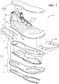
- an article of footwear 10 is provided and includes an upper structure 12 and a sole structure 14 attached to the upper structure 12.
- the article of footwear 10 may be divided into one or more regions. As seen in FIG. 1 , the regions may include a forefoot region 16, a midfoot region 18, and a heel region 20.
- the forefoot region 16 may correspond with toes and joints connecting metatarsal bones with phalanx bones of a foot, and may include an anterior end 22 of the article of footwear 10.
- the midfoot region 18 may correspond with an arch area of the foot while the heel region 20 may correspond with rear portions of the foot, including a calcaneus bone, and may include a posterior end 24 of the article of footwear 10.
- the article of footwear 10 may additionally include a medial side 26 and a lateral side 28 that correspond with opposite sides of the article of footwear 10 and extend through the regions 16, 18, 20.
- the upper structure 12 includes interior surfaces that define an interior foot-receiving void 30 (see FIGS. 4-5 ) that is sized for receiving and securing a foot for support on the sole structure 14.
- An ankle opening 32 in the heel region 20 may provide access to the interior foot-receiving void 30.
- the ankle opening 32 may receive a foot to secure the foot within the void 30 and facilitate entry and removal of the foot from and to the interior foot-receiving void 30.
- one or more fasteners 34 extend along the upper structure 12 to adjust a fit of the upper structure 12 around the foot while concurrently accommodating entry and removal of the foot therefrom.
- the upper structure 12 may include apertures 36 such as eyelets and/or other engagement features such as fabric or mesh loops that receive the fasteners 34.
- the fasteners 34 may include laces, straps, cords, hook-and-loop, or any other suitable type of fastener.
- the upper structure 12 may additionally include a tongue portion 38 that extends between the interior foot-receiving void 30 and the fasteners 34.
- the upper structure 12 includes a strobel 40 (see FIGS. 3-5 and 7 ) configured to enclose a bottom portion of the interior foot-receiving void 30.
- the strobel 40 may be joined to the upper structure 12 using stitching.
- the strobel 40 may additionally or alternatively be adhesively bonded to the upper structure 12, and may include multiple layers of material.
- the upper structure 12 includes one or more materials, such as a plurality of sheets or layers of material 70, 72, 74, that are stitched or adhesively bonded together to form the interior foot-receiving void 30.
- Suitable materials of the upper structure 12 may include, textiles, foam, leather, and synthetic leather. The materials may be selected and located to impart properties of durability, air-permeability, wear-resistance, flexibility, and comfort to the foot while disposed within the interior foot-receiving void 30.
- the sole structure 14 is attached to the upper structure 12 and provides the article of footwear 10 with support and cushioning during use.
- the sole structure 14 may attenuate ground-reaction forces caused by the article of footwear 10 striking the ground during use.
- the sole structure 14 may incorporate one or more materials having energy absorbing characteristics to allow the sole structure 14 to minimize the impact experienced by a user when wearing the article of footwear 10.
- the sole structure 14 may include different layers, such as, for example, an outsole 42, a midsole 44 and a sockliner or insole 46.
- Each layer may serve a particular function.
- the outsole 42 may include a plurality of regions having different hardness characteristics (e.g., sticky rubber for providing higher friction and hard rubber forming cleats) that react differently when engaged with an underlying ground surface.
- one or both of the midsole 44 and the insole 46 may be designed to contact the foot to provide enhanced comfort to the foot.
- the insole 46 may be disposed within the interior foot-receiving void 30. In an example as seen in FIG.
- the insole 46 when the upper structure 12 includes the strobel 40, the insole 46 is formed separately from the midsole 44, and is disposed on an opposite side of the strobel 40 from the midsole 44. In other examples, where the upper structure 12 does not include the strobel 40, the insole 46 may include a layer formed into the sole structure 14 such that the insole 46 is disposed adjacent to the midsole 44 in an assembled configuration. A material, or combination of materials, of the insole 46 may be selected to impart properties of cushioning, stability, ventilation, and breathability.
- the midsole 44 may be disposed between the strobel 40 and the outsole 42. As shown, the midsole 44 opposes the strobel 40 and is disposed between the strobel 40 and the outsole 42. However, as discussed above, the strobel 40 may not be included in some configurations, and the midsole 44 may be disposed directly between the insole 46 and the outsole 42. Furthermore, the upper structure 12 may optionally include one or more trim bands 48, 50 such as, for example, forefoot region trim band 48 and a heel region trim band 50 that is disposed over and trims one or more exterior surfaces of the strobel 40, the outsole 42 or the midsole 44.
- trim bands 48, 50 such as, for example, forefoot region trim band 48 and a heel region trim band 50 that is disposed over and trims one or more exterior surfaces of the strobel 40, the outsole 42 or the midsole 44.
- the upper structure 12 includes a cuff member 52 attached to an upper 54.
- the upper structure 12 may also optionally include the strobel 40.
- the cuff member 52 defines the ankle opening 32. Furthermore, as seen in FIG. 4 , the cuff member 52 may also include the tongue portion 38.
- the cuff member 52 includes a sheet or layer of material that is folded upon itself, defining a cuff void 56.
- the sheet or layer of material of the cuff member 52 includes a first end 58 and a second end 60 that are secured to the upper 54.
- the cuff member 52 when the cuff member 52 is arranged in the folded configuration, the cuff member 52 includes an exterior cuff portion 62, an interior cuff portion 64 and an intermediate cuff portion 66 connecting the exterior cuff portion 62 to the interior cuff portion 64.
- the interior cuff portion 64 defines an ankle-receiving void 68 that is sized for receiving and conforming to a user's ankle.
- the intermediate cuff portion 66 defines the ankle opening 32.
- the exterior cuff portion 62 faces a surrounding environment.
- the exterior cuff portion 62 includes the first end 58 of the sheet or layer of material of the cuff member 52.
- the interior cuff portion 64 includes the second end 60 of the sheet or layer of material of the cuff member 52.
- the sheet or layer of material of the cuff member 52 may be a conformable material.
- the conformable material permits the cuff member 52 to conform to a user's ankle in order to mitigate intrusion of debris (e.g., dirt, mud, stones, pebbles, rocks, twigs and the like) into one or more of the interior foot-receiving void 30 that receives and secures the user's foot and the ankle-receiving void 68 that is sized for receiving the user's ankle.
- the conformable material of the cuff member 52 includes an elastic material.
- the conformable material may be a knit material.
- the conformable knit material allows heat and moisture to pass from one or more of the interior foot-receiving void 30 and the ankle-receiving void 68 to the surrounding environment in order to increase comfort when the user's foot and ankle are respectively disposed within the interior foot-receiving void 30 and the ankle-receiving void 68.
- the upper 54 includes the plurality of sheets or layers of material 70-74.
- the plurality of sheets or layers of material 70-74 of the upper 54 includes an exterior upper member 70 and an interior upper member 72.
- the plurality of sheets or layers of material 70-74 of the upper 54 includes an intermediate upper member 74 arranged between the exterior upper member 70 and the interior upper member 72.
- the exterior upper member 70 faces surrounding environment.
- the interior upper member 72 at least partially defines the interior foot-receiving void 30.
- the plurality of sheets or layers of material 70-74 of the upper 54 may include elastic or inelastic materials.
- the interior upper member 72 of the plurality of sheets or layers of material 70-74 may include an elastic material and the exterior upper member 70 of the plurality of sheets or layers of material 70-74 may include an inelastic material.
- the elastic material defining the interior upper member 72 may be spandex.
- the exterior upper member 70 may include, but is not limited to textiles, foam, leather, and synthetic leather.
- the intermediate upper member 74 may include, but is not limited to textiles, foam, leather, and synthetic leather.
- the exterior upper member 70 is secured to the exterior cuff portion 62 by a first fastener 76 and the interior upper member 72 is secured to the interior cuff portion 64 by a second fastener 78.
- the first fastener 76 may extend through both of the exterior upper member 70 and the exterior cuff portion 62 while not extending through the intermediate upper member 74, the interior cuff portion 64 or the interior upper member 72.
- the second fastener 78 may extend through both of the interior upper member 72 and the interior cuff portion 64 while not extending through the intermediate upper member 74, the exterior cuff portion 62 or the exterior upper member 70.
- each of the first fastener 76 and the second fastener 78 is a thread resulting in a sewn or stitched connection of a layer or sheet of material of the exterior cuff portion 62 to the layer or sheet of material of the exterior upper member 70 and of a layer or sheet of material of the interior cuff portion 64 to the layer or sheet of material of the interior upper member 72, as described above.
- first fastener 76 and the second fastener 78 may include a thread resulting in a sewn or stitched connection
- first fastener 76 or the second fastener 78 may alternatively or additionally include other fastener materials such as, for example, adhesive for connecting the layers or sheets of material of the exterior cuff portion 62 and exterior upper member 70 and the layer or sheets of material of the interior cuff portion 64 and the intermediate upper member 72, as described above.
- the exterior upper member 70 is secured to and disposed adjacent an exterior surface 80 of the exterior cuff portion 62
- the interior upper member 72 is secured to and disposed adjacent an exterior surface 82 of the interior cuff portion 64.
- the exterior surface 80, 82 of each of the exterior cuff portion 62 and the interior cuff portion 64 do not define the cuff void 56 (i.e., an interior surface 84, 86 of each of the exterior cuff portion 62 and the interior cuff portion 64 defines the cuff void 56).
- the intermediate upper member 74 extends into the cuff void 56 such that the intermediate upper member 74 is disposed adjacent or opposite the interior surface 84, 86 of each of the exterior cuff portion 62 and the interior cuff portion 64. Accordingly, the intermediate upper member 74 is disposed between the exterior cuff portion 62 and the interior cuff portion 64.
- the upper 54 is secured to the strobel 40.
- the upper 54 is secured to the strobel 40 by a third fastener 88.
- the third fastener 88 extends through the strobel 40 and at least the interior upper member 72 that may include an elastic material (e.g. spandex).
- the third fastener 88 extends through the strobel 40 and at least the exterior upper member 70 that may include an inelastic material.
- the third fastener 88 extends through the strobel 40, the exterior upper member 70 that may include an inelastic material and the interior upper member 72 that may include an elastic material (e.g., spandex).
- the third fastener 88 extends through the strobel 40, the exterior upper member 70 that may include an inelastic material, the interior upper member 72 that may include an elastic material (e.g., spandex) and the intermediate upper member 74.
- the upper structure 12 may optionally include a heel counter 90.
- the heel counter 90 may be secured to or disposed over a portion of the interior cuff portion 64 of the cuff member 52.
- the heel counter 90 may also be secured to or disposed over the interior upper member 72 of the upper 54.
- the upper structure 12 may further include a first pull tab 92 and a second pull tab 94.
- the first pull tab 92 or the second pull tab 94 may be secured to the cuff member 52.
- the first or second pull tabs 92, 94 are secured to the exterior cuff portion 62 of the cuff member 52 and are arranged near or proximate the intermediate cuff portion 66 of the cuff member 52 such that the first or second pull tabs 92, 94 are arranged near or proximate the ankle opening 32.
- the first pull tab 92 may be an anterior pull tab 92 secured to an anterior region 96 of the exterior cuff portion 62 of the cuff member 52
- the second pull tab 94 may be a posterior pull tab 94 secured to a posterior region 98 of the exterior cuff portion 62 of the cuff member 52
- the first or second pull tabs 92, 94 may include both of the anterior pull tab 92 secured to the anterior region 96 of the exterior cuff portion 62 of the cuff member 52 and the posterior pull tab 94 secured to the posterior region 98 of the exterior cuff portion 62 of the cuff member 52.
- the anterior region 96 of the exterior cuff portion 62 includes at least some of the tongue portion 38 of the article of footwear 10. In another example, the anterior region 96 of the exterior cuff portion 62 is located between a medial region of the exterior cuff portion 62 and a lateral region of the exterior cuff portion 62.
- the posterior region 98 of the exterior cuff portion 62 includes at least a portion of a heel region of the article of footwear 10. In another example, the posterior region 98 of the exterior cuff portion 62 is located between the medial region of the exterior cuff portion 62 and the lateral region of the exterior cuff portion 62.
- the foregoing article of footwear 10 incorporates an upper structure 12 having a cuff member 52 and upper 54 that provide a degree of comfort and conformability to a user's ankle while mitigating intrusion of debris (e.g., dirt, mud, stones, pebbles, rocks, twigs and the like) into one or more of the interior foot-receiving void 30 that receives and secures the user's foot and the ankle-receiving void 68 that is sized for receiving the user's ankle user during use of the particular article of footwear 10.
- debris e.g., dirt, mud, stones, pebbles, rocks, twigs and the like
- the foregoing article of footwear 10 incorporates an outsole 42 that includes a plurality of regions having different hardness characteristics (e.g., sticky rubber for providing higher friction and hard rubber forming cleats) that react differently when engaged with an underlying ground surface. Accordingly, the article of footwear 10 may be used for a variety of athletic activities such as hiking, biking, rock climbing, running, basketball, or the like.
- hardness characteristics e.g., sticky rubber for providing higher friction and hard rubber forming cleats
- the article of footwear 10 may be used for a variety of athletic activities such as hiking, biking, rock climbing, running, basketball, or the like.
Landscapes
- Chemical & Material Sciences (AREA)
- Engineering & Computer Science (AREA)
- Materials Engineering (AREA)
- Health & Medical Sciences (AREA)
- General Health & Medical Sciences (AREA)
- Physical Education & Sports Medicine (AREA)
- Epidemiology (AREA)
- Public Health (AREA)
- Footwear And Its Accessory, Manufacturing Method And Apparatuses (AREA)
Claims (15)
- Structure de tige (12) d'un article chaussant, la structure de tige (12) comprenant :une tige (54) incluant un élément de tige extérieur (70) et un élément de tige intérieur (72) ;un élément de bracelet (52) incluant une première extrémité (58) couplée à l'élément de tige extérieur (70) et une seconde extrémité (60) couplée à l'élément de tige intérieur (72), l'élément de bracelet (52) étant replié sur luimême au niveau d'un pli pour définir une ouverture de cheville (32) ; etun strobel (40) couplé à la tige (54) et coopérant avec la tige (54) pour définir au moins partiellement un vide de réception de pied (30),dans laquelle la première extrémité (58) de l'élément de bracelet (52) est fixée à l'élément de tige extérieur (70) par une première attache (76) et la seconde extrémité (60) de l'élément de bracelet (52) est fixée à l'élément de tige intérieur (72) par une deuxième attache (78), etdans laquelle la tige (54) inclut en outre :
un élément de tige intermédiaire (74) disposé entre l'élément de tige extérieur (70) et l'élément de tige intérieur (72), l'élément de tige intermédiaire (74) s'étendant entre des portions opposées de l'élément de bracelet (52) et étant agencé entre la première extrémité (58) de l'élément de bracelet (52) et la seconde extrémité (60) de l'élément de bracelet (52). - Structure de tige (12) selon la revendication 1, dans laquelle l'élément de bracelet (52) est formé d'un matériau tricoté.
- Structure de tige (12) selon la revendication 1, dans laquelle l'élément de tige intérieur (72) est formé d'un matériau élastique, qui est de préférence de l'élasthanne ; ou
dans laquelle l'élément de tige extérieur (70) est formé d'un matériau inélastique. - Structure de tige (12) selon la revendication 1, dans laquelle la première attache (76) s'étend à travers l'élément de tige extérieur (70) et la deuxième attache (78) s'étend à travers l'élément de tige intérieur (72).
- Structure de tige (12) selon la revendication 1, dans laquelle le strobel (40) est fixé à la tige (54) par une troisième attache (88) s'étendant à travers le strobel (40) et au moins l'élément de tige intérieur (72).
- Structure de tige (12) selon la revendication 5, dans laquelle la troisième attache (88) s'étend à travers l'élément de tige extérieur (70).
- Structure de tige (12) selon la revendication 5, dans laquelle la troisième attache (88) s'étend à travers l'élément de tige intermédiaire (74).
- Structure de tige (12) selon la revendication 1, dans laquelle l'élément de bracelet (52) inclut une portion de bracelet extérieure (62), une portion de bracelet intérieure (64), et une portion de bracelet intermédiaire (66) connectant la portion de bracelet extérieure (62) à la portion de bracelet intérieure (64), la portion de bracelet extérieure (62) incluant la première extrémité (58) de l'élément de bracelet (52) et la portion de bracelet intérieure (64) incluant la seconde extrémité (60) de l'élément de bracelet (52).
- Structure de tige (12) selon la revendication 8, dans laquelle la portion de bracelet intérieure (64) s'oppose à la portion de bracelet extérieure (62).
- Structure de tige (12) selon la revendication 8, comprenant en outre un contrefort de talon (90) fixé à l'élément de tige intérieur (72) et la portion de bracelet intérieure (64), dans laquelle le contrefort de talon (90) s'étend de préférence au moins partiellement sur et est fixé à la portion de bracelet intérieure (64) de l'élément de bracelet (52).
- Structure de tige (12) selon la revendication 8, comprenant en outre un tirant antérieur (92) fixé à une région antérieure (96) de la portion de bracelet extérieure (62).
- Structure de tige (12) selon la revendication 11, dans laquelle la région antérieure (96) de la portion de bracelet extérieure (62) inclut une région de languette de la portion de bracelet extérieure (62) et est située entre une région médiale de la portion de bracelet extérieure (62) et une région latérale de la portion de bracelet extérieure (62).
- Structure de tige (12) selon la revendication 11, dans laquelle le tirant antérieur (92) est agencé sur la portion de bracelet extérieure (62) à proximité de la portion de bracelet intermédiaire (66).
- Structure de tige (12) selon la revendication 8, comprenant en outre un tirant postérieur (92) fixé à une région postérieure (98) de la portion de bracelet extérieure (62).
- Structure de tige (12) selon la revendication 14, dans laquelle la région postérieure (98) de la portion de bracelet extérieure (62) inclut au moins partiellement une région de talon de la portion de bracelet extérieure (62) et est située entre une région médiale de la portion de bracelet extérieure (62) et une région latérale de la portion de bracelet extérieure (62) ; ou
dans laquelle le tirant postérieur (92) est agencé sur la portion de bracelet extérieure (62) à proximité de la portion de bracelet intermédiaire (66).
Priority Applications (1)
| Application Number | Priority Date | Filing Date | Title |
|---|---|---|---|
| EP22209159.7A EP4159074B1 (fr) | 2018-12-31 | 2019-12-27 | Structure de tige d'un article chaussant comprenant un élément de manchon |
Applications Claiming Priority (2)
| Application Number | Priority Date | Filing Date | Title |
|---|---|---|---|
| US201862786708P | 2018-12-31 | 2018-12-31 | |
| PCT/US2019/068674 WO2020142357A1 (fr) | 2018-12-31 | 2019-12-27 | Structure de tige d'un article chaussant comprenant un élément de manchon |
Related Child Applications (2)
| Application Number | Title | Priority Date | Filing Date |
|---|---|---|---|
| EP22209159.7A Division EP4159074B1 (fr) | 2018-12-31 | 2019-12-27 | Structure de tige d'un article chaussant comprenant un élément de manchon |
| EP22209159.7A Division-Into EP4159074B1 (fr) | 2018-12-31 | 2019-12-27 | Structure de tige d'un article chaussant comprenant un élément de manchon |
Publications (2)
| Publication Number | Publication Date |
|---|---|
| EP3905914A1 EP3905914A1 (fr) | 2021-11-10 |
| EP3905914B1 true EP3905914B1 (fr) | 2022-12-28 |
Family
ID=69185760
Family Applications (2)
| Application Number | Title | Priority Date | Filing Date |
|---|---|---|---|
| EP22209159.7A Active EP4159074B1 (fr) | 2018-12-31 | 2019-12-27 | Structure de tige d'un article chaussant comprenant un élément de manchon |
| EP19839788.7A Active EP3905914B1 (fr) | 2018-12-31 | 2019-12-27 | Structure de tige d'un article chaussant comprenant un élément de manchon |
Family Applications Before (1)
| Application Number | Title | Priority Date | Filing Date |
|---|---|---|---|
| EP22209159.7A Active EP4159074B1 (fr) | 2018-12-31 | 2019-12-27 | Structure de tige d'un article chaussant comprenant un élément de manchon |
Country Status (4)
| Country | Link |
|---|---|
| US (1) | US12004594B2 (fr) |
| EP (2) | EP4159074B1 (fr) |
| CN (2) | CN113260267B (fr) |
| WO (1) | WO2020142357A1 (fr) |
Families Citing this family (9)
| Publication number | Priority date | Publication date | Assignee | Title |
|---|---|---|---|---|
| CN110730835B (zh) | 2017-05-05 | 2022-03-04 | 耐克创新有限合伙公司 | 具有第一针织部分和第二针织部分的用于鞋类物品的鞋面以及制造鞋面的方法 |
| WO2020252171A1 (fr) | 2019-06-11 | 2020-12-17 | Karnali Innovations LLC | Semelles de chaussure anti-infectieuses |
| USD974005S1 (en) | 2020-12-23 | 2023-01-03 | Specialized Bicycle Components, Inc. | Shoe |
| USD1050685S1 (en) * | 2021-10-15 | 2024-11-12 | Specialized Bicycle Components, Inc. | Shoe |
| USD1052853S1 (en) * | 2021-12-06 | 2024-12-03 | Specialized Bicycle Components, Inc. | Shoe |
| USD1001428S1 (en) * | 2022-05-24 | 2023-10-17 | Anta (China) Co., Ltd. | Shoe |
| USD1044215S1 (en) * | 2023-06-30 | 2024-10-01 | Anta (China) Co., Ltd. | Shoe |
| USD1115279S1 (en) * | 2024-03-22 | 2026-03-03 | Wolverine Outdoors, Inc. | Footwear upper |
| USD1115280S1 (en) * | 2024-03-22 | 2026-03-03 | Wolverine Outdoors, Inc. | Footwear upper |
Family Cites Families (26)
| Publication number | Priority date | Publication date | Assignee | Title |
|---|---|---|---|---|
| GB190312787A (en) * | 1903-06-06 | 1904-06-06 | Karl Daut | Improvements in and relating to the Manufacture of Boots or Shoes. |
| US3374561A (en) * | 1965-10-20 | 1968-03-26 | Rosemount Eng Co Ltd | Hydrostatic pad for ski boot |
| US3478738A (en) * | 1966-07-15 | 1969-11-18 | Max S Altman | Bathing boot with means to massage foot |
| US4451996A (en) * | 1982-03-22 | 1984-06-05 | New Balance Athletic Shoe, Inc. | Athletic shoe with collar |
| US4662088A (en) * | 1985-04-29 | 1987-05-05 | Autry Industries, Inc. | Achilles tendon protection and support pad |
| US4852275A (en) * | 1986-09-25 | 1989-08-01 | Highland Import Corporation | Shoe having a rigid back part |
| US5060402A (en) * | 1989-02-17 | 1991-10-29 | Rosen Henri E | Adjustable girth shoe construction |
| US5172493A (en) * | 1989-11-29 | 1992-12-22 | At & S Specialties, Inc. | Protective cover for shoes, boots and the like |
| IT1248692B (it) * | 1990-06-05 | 1995-01-26 | Calzaturificio Tecnica | Scarpetta interna dinamica perfezionata per scarponi |
| US5611156A (en) * | 1995-04-21 | 1997-03-18 | Chiu; Chang H. | Reflective shoe |
| US5765296A (en) * | 1997-01-31 | 1998-06-16 | Nine West Group, Inc. | Exercise shoe having fit adaptive upper |
| US5848484A (en) * | 1997-02-03 | 1998-12-15 | Dupree; Tony L. | Convertible athletic shoe |
| AU5104899A (en) * | 1998-12-22 | 2000-07-12 | Reebok International Ltd. | An article of footwear and method for making the same |
| US20220234336A1 (en) * | 2003-01-15 | 2022-07-28 | Solid Water Holdings | Softboots and waterproof/breathable moisture transfer composite and liner for in-line skates, ice-skates, hockey skates, snowboard boots, alpine boots, hiking boots and the like |
| US7082704B2 (en) * | 2004-07-30 | 2006-08-01 | James L. Throneburg | Insole, and footwear system incorporating same |
| US7574818B2 (en) * | 2006-05-25 | 2009-08-18 | Nike, Inc. | Article of footwear having an upper with thread structural elements |
| US8122616B2 (en) * | 2008-07-25 | 2012-02-28 | Nike, Inc. | Composite element with a polymer connecting layer |
| US9149086B2 (en) | 2009-10-07 | 2015-10-06 | Nike, Inc. | Article of footwear having an upper with knitted elements |
| CN102232661A (zh) * | 2011-05-09 | 2011-11-09 | 汤汉忠 | 散热保健休闲鞋 |
| US20140013621A1 (en) * | 2012-07-10 | 2014-01-16 | Cabrio Footwear, Inc. | Convertible Footwear |
| US10182617B2 (en) * | 2012-11-20 | 2019-01-22 | Nike, Inc. | Footwear upper incorporating a knitted component with collar and throat portions |
| US20150059209A1 (en) * | 2013-08-29 | 2015-03-05 | Nike, Inc. | Article Of Footwear Incorporating A Knitted Component With An Integral Knit Ankle Cuff |
| US9713362B2 (en) * | 2013-09-12 | 2017-07-25 | Nike, Inc. | Article of footwear with upper having member with support arm |
| DE102015219636B4 (de) * | 2015-10-09 | 2023-11-23 | Adidas Ag | Herstellungsverfahren zum Beschichten eines Gewebes mit einer dreidimensionalen Form |
| CN205072189U (zh) * | 2015-10-26 | 2016-03-09 | 三六一度(中国)有限公司 | 超轻透气休闲鞋 |
| CN107874384B (zh) * | 2017-10-09 | 2020-03-27 | 安徽嘉盛鞋业有限公司 | 一种用于鞋子的脚后跟稳定器 |
-
2019
- 2019-12-27 CN CN201980087362.XA patent/CN113260267B/zh active Active
- 2019-12-27 EP EP22209159.7A patent/EP4159074B1/fr active Active
- 2019-12-27 CN CN202211045458.XA patent/CN115413845A/zh active Pending
- 2019-12-27 US US17/420,016 patent/US12004594B2/en active Active
- 2019-12-27 EP EP19839788.7A patent/EP3905914B1/fr active Active
- 2019-12-27 WO PCT/US2019/068674 patent/WO2020142357A1/fr not_active Ceased
Also Published As
| Publication number | Publication date |
|---|---|
| EP4159074A1 (fr) | 2023-04-05 |
| CN113260267B (zh) | 2022-09-16 |
| US12004594B2 (en) | 2024-06-11 |
| WO2020142357A1 (fr) | 2020-07-09 |
| CN113260267A (zh) | 2021-08-13 |
| EP3905914A1 (fr) | 2021-11-10 |
| CN115413845A (zh) | 2022-12-02 |
| EP4159074B1 (fr) | 2025-10-01 |
| US20220087365A1 (en) | 2022-03-24 |
Similar Documents
| Publication | Publication Date | Title |
|---|---|---|
| EP3905914B1 (fr) | Structure de tige d'un article chaussant comprenant un élément de manchon | |
| EP3616546B1 (fr) | Chaussure de mouvement confortable | |
| EP2925176B1 (fr) | Article chaussant ayant une tige élastique renforcée | |
| EP4030953B1 (fr) | Structure de semelle de chaussure et tige avec plaque intégrée | |
| US7624517B2 (en) | Article of footwear with saddle | |
| EP2996507B1 (fr) | Article chaussant ayant une portion de talon avec composant tricoté | |
| US7810257B2 (en) | Article of footwear with removable upper | |
| US12357056B2 (en) | Sole structure having differing hardness regions | |
| EP3510885A1 (fr) | Article chaussant ayant une structure de semelle | |
| WO2007149217A2 (fr) | Article chaussant modulaire | |
| US20170238658A1 (en) | Footwear Upper With Zonal Support Areas | |
| US11109637B2 (en) | Cushioning arrangement for temperature control of a sole structure | |
| EP3054803B1 (fr) | Article chaussant avec une structure de semelle | |
| US12310454B2 (en) | Article of footwear including a support flap | |
| EP3139784B1 (fr) | Tige d'article chaussant comportant un rembourrage positionné sélectivement | |
| HK1215363B (en) | Article of footwear having heel portion with knitted component |
Legal Events
| Date | Code | Title | Description |
|---|---|---|---|
| STAA | Information on the status of an ep patent application or granted ep patent |
Free format text: STATUS: UNKNOWN |
|
| STAA | Information on the status of an ep patent application or granted ep patent |
Free format text: STATUS: THE INTERNATIONAL PUBLICATION HAS BEEN MADE |
|
| PUAI | Public reference made under article 153(3) epc to a published international application that has entered the european phase |
Free format text: ORIGINAL CODE: 0009012 |
|
| STAA | Information on the status of an ep patent application or granted ep patent |
Free format text: STATUS: REQUEST FOR EXAMINATION WAS MADE |
|
| 17P | Request for examination filed |
Effective date: 20210722 |
|
| AK | Designated contracting states |
Kind code of ref document: A1 Designated state(s): AL AT BE BG CH CY CZ DE DK EE ES FI FR GB GR HR HU IE IS IT LI LT LU LV MC MK MT NL NO PL PT RO RS SE SI SK SM TR |
|
| DAV | Request for validation of the european patent (deleted) | ||
| DAX | Request for extension of the european patent (deleted) | ||
| GRAP | Despatch of communication of intention to grant a patent |
Free format text: ORIGINAL CODE: EPIDOSNIGR1 |
|
| STAA | Information on the status of an ep patent application or granted ep patent |
Free format text: STATUS: GRANT OF PATENT IS INTENDED |
|
| INTG | Intention to grant announced |
Effective date: 20220726 |
|
| GRAS | Grant fee paid |
Free format text: ORIGINAL CODE: EPIDOSNIGR3 |
|
| GRAA | (expected) grant |
Free format text: ORIGINAL CODE: 0009210 |
|
| STAA | Information on the status of an ep patent application or granted ep patent |
Free format text: STATUS: THE PATENT HAS BEEN GRANTED |
|
| AK | Designated contracting states |
Kind code of ref document: B1 Designated state(s): AL AT BE BG CH CY CZ DE DK EE ES FI FR GB GR HR HU IE IS IT LI LT LU LV MC MK MT NL NO PL PT RO RS SE SI SK SM TR |
|
| REG | Reference to a national code |
Ref country code: GB Ref legal event code: FG4D |
|
| REG | Reference to a national code |
Ref country code: CH Ref legal event code: EP |
|
| REG | Reference to a national code |
Ref country code: DE Ref legal event code: R096 Ref document number: 602019023790 Country of ref document: DE |
|
| REG | Reference to a national code |
Ref country code: AT Ref legal event code: REF Ref document number: 1539878 Country of ref document: AT Kind code of ref document: T Effective date: 20230115 |
|
| REG | Reference to a national code |
Ref country code: IE Ref legal event code: FG4D |
|
| REG | Reference to a national code |
Ref country code: LT Ref legal event code: MG9D |
|
| PG25 | Lapsed in a contracting state [announced via postgrant information from national office to epo] |
Ref country code: SE Free format text: LAPSE BECAUSE OF FAILURE TO SUBMIT A TRANSLATION OF THE DESCRIPTION OR TO PAY THE FEE WITHIN THE PRESCRIBED TIME-LIMIT Effective date: 20221228 Ref country code: NO Free format text: LAPSE BECAUSE OF FAILURE TO SUBMIT A TRANSLATION OF THE DESCRIPTION OR TO PAY THE FEE WITHIN THE PRESCRIBED TIME-LIMIT Effective date: 20230328 Ref country code: LT Free format text: LAPSE BECAUSE OF FAILURE TO SUBMIT A TRANSLATION OF THE DESCRIPTION OR TO PAY THE FEE WITHIN THE PRESCRIBED TIME-LIMIT Effective date: 20221228 Ref country code: FI Free format text: LAPSE BECAUSE OF FAILURE TO SUBMIT A TRANSLATION OF THE DESCRIPTION OR TO PAY THE FEE WITHIN THE PRESCRIBED TIME-LIMIT Effective date: 20221228 |
|
| REG | Reference to a national code |
Ref country code: NL Ref legal event code: MP Effective date: 20221228 |
|
| REG | Reference to a national code |
Ref country code: AT Ref legal event code: MK05 Ref document number: 1539878 Country of ref document: AT Kind code of ref document: T Effective date: 20221228 |
|
| PG25 | Lapsed in a contracting state [announced via postgrant information from national office to epo] |
Ref country code: RS Free format text: LAPSE BECAUSE OF FAILURE TO SUBMIT A TRANSLATION OF THE DESCRIPTION OR TO PAY THE FEE WITHIN THE PRESCRIBED TIME-LIMIT Effective date: 20221228 Ref country code: LV Free format text: LAPSE BECAUSE OF FAILURE TO SUBMIT A TRANSLATION OF THE DESCRIPTION OR TO PAY THE FEE WITHIN THE PRESCRIBED TIME-LIMIT Effective date: 20221228 Ref country code: HR Free format text: LAPSE BECAUSE OF FAILURE TO SUBMIT A TRANSLATION OF THE DESCRIPTION OR TO PAY THE FEE WITHIN THE PRESCRIBED TIME-LIMIT Effective date: 20221228 Ref country code: GR Free format text: LAPSE BECAUSE OF FAILURE TO SUBMIT A TRANSLATION OF THE DESCRIPTION OR TO PAY THE FEE WITHIN THE PRESCRIBED TIME-LIMIT Effective date: 20230329 |
|
| P01 | Opt-out of the competence of the unified patent court (upc) registered |
Effective date: 20230515 |
|
| PG25 | Lapsed in a contracting state [announced via postgrant information from national office to epo] |
Ref country code: NL Free format text: LAPSE BECAUSE OF FAILURE TO SUBMIT A TRANSLATION OF THE DESCRIPTION OR TO PAY THE FEE WITHIN THE PRESCRIBED TIME-LIMIT Effective date: 20221228 |
|
| PG25 | Lapsed in a contracting state [announced via postgrant information from national office to epo] |
Ref country code: SM Free format text: LAPSE BECAUSE OF FAILURE TO SUBMIT A TRANSLATION OF THE DESCRIPTION OR TO PAY THE FEE WITHIN THE PRESCRIBED TIME-LIMIT Effective date: 20221228 Ref country code: RO Free format text: LAPSE BECAUSE OF FAILURE TO SUBMIT A TRANSLATION OF THE DESCRIPTION OR TO PAY THE FEE WITHIN THE PRESCRIBED TIME-LIMIT Effective date: 20221228 Ref country code: PT Free format text: LAPSE BECAUSE OF FAILURE TO SUBMIT A TRANSLATION OF THE DESCRIPTION OR TO PAY THE FEE WITHIN THE PRESCRIBED TIME-LIMIT Effective date: 20230428 Ref country code: ES Free format text: LAPSE BECAUSE OF FAILURE TO SUBMIT A TRANSLATION OF THE DESCRIPTION OR TO PAY THE FEE WITHIN THE PRESCRIBED TIME-LIMIT Effective date: 20221228 Ref country code: EE Free format text: LAPSE BECAUSE OF FAILURE TO SUBMIT A TRANSLATION OF THE DESCRIPTION OR TO PAY THE FEE WITHIN THE PRESCRIBED TIME-LIMIT Effective date: 20221228 Ref country code: CZ Free format text: LAPSE BECAUSE OF FAILURE TO SUBMIT A TRANSLATION OF THE DESCRIPTION OR TO PAY THE FEE WITHIN THE PRESCRIBED TIME-LIMIT Effective date: 20221228 Ref country code: AT Free format text: LAPSE BECAUSE OF FAILURE TO SUBMIT A TRANSLATION OF THE DESCRIPTION OR TO PAY THE FEE WITHIN THE PRESCRIBED TIME-LIMIT Effective date: 20221228 |
|
| PG25 | Lapsed in a contracting state [announced via postgrant information from national office to epo] |
Ref country code: SK Free format text: LAPSE BECAUSE OF FAILURE TO SUBMIT A TRANSLATION OF THE DESCRIPTION OR TO PAY THE FEE WITHIN THE PRESCRIBED TIME-LIMIT Effective date: 20221228 Ref country code: PL Free format text: LAPSE BECAUSE OF FAILURE TO SUBMIT A TRANSLATION OF THE DESCRIPTION OR TO PAY THE FEE WITHIN THE PRESCRIBED TIME-LIMIT Effective date: 20221228 Ref country code: IS Free format text: LAPSE BECAUSE OF FAILURE TO SUBMIT A TRANSLATION OF THE DESCRIPTION OR TO PAY THE FEE WITHIN THE PRESCRIBED TIME-LIMIT Effective date: 20230428 Ref country code: AL Free format text: LAPSE BECAUSE OF FAILURE TO SUBMIT A TRANSLATION OF THE DESCRIPTION OR TO PAY THE FEE WITHIN THE PRESCRIBED TIME-LIMIT Effective date: 20221228 |
|
| REG | Reference to a national code |
Ref country code: DE Ref legal event code: R097 Ref document number: 602019023790 Country of ref document: DE |
|
| PG25 | Lapsed in a contracting state [announced via postgrant information from national office to epo] |
Ref country code: DK Free format text: LAPSE BECAUSE OF FAILURE TO SUBMIT A TRANSLATION OF THE DESCRIPTION OR TO PAY THE FEE WITHIN THE PRESCRIBED TIME-LIMIT Effective date: 20221228 |
|
| PLBE | No opposition filed within time limit |
Free format text: ORIGINAL CODE: 0009261 |
|
| STAA | Information on the status of an ep patent application or granted ep patent |
Free format text: STATUS: NO OPPOSITION FILED WITHIN TIME LIMIT |
|
| 26N | No opposition filed |
Effective date: 20230929 |
|
| PG25 | Lapsed in a contracting state [announced via postgrant information from national office to epo] |
Ref country code: SI Free format text: LAPSE BECAUSE OF FAILURE TO SUBMIT A TRANSLATION OF THE DESCRIPTION OR TO PAY THE FEE WITHIN THE PRESCRIBED TIME-LIMIT Effective date: 20221228 |
|
| PG25 | Lapsed in a contracting state [announced via postgrant information from national office to epo] |
Ref country code: IT Free format text: LAPSE BECAUSE OF FAILURE TO SUBMIT A TRANSLATION OF THE DESCRIPTION OR TO PAY THE FEE WITHIN THE PRESCRIBED TIME-LIMIT Effective date: 20221228 |
|
| REG | Reference to a national code |
Ref country code: CH Ref legal event code: PL |
|
| PG25 | Lapsed in a contracting state [announced via postgrant information from national office to epo] |
Ref country code: LU Free format text: LAPSE BECAUSE OF NON-PAYMENT OF DUE FEES Effective date: 20231227 |
|
| PG25 | Lapsed in a contracting state [announced via postgrant information from national office to epo] |
Ref country code: MC Free format text: LAPSE BECAUSE OF FAILURE TO SUBMIT A TRANSLATION OF THE DESCRIPTION OR TO PAY THE FEE WITHIN THE PRESCRIBED TIME-LIMIT Effective date: 20221228 |
|
| REG | Reference to a national code |
Ref country code: BE Ref legal event code: MM Effective date: 20231231 |
|
| PG25 | Lapsed in a contracting state [announced via postgrant information from national office to epo] |
Ref country code: MC Free format text: LAPSE BECAUSE OF FAILURE TO SUBMIT A TRANSLATION OF THE DESCRIPTION OR TO PAY THE FEE WITHIN THE PRESCRIBED TIME-LIMIT Effective date: 20221228 Ref country code: LU Free format text: LAPSE BECAUSE OF NON-PAYMENT OF DUE FEES Effective date: 20231227 |
|
| REG | Reference to a national code |
Ref country code: IE Ref legal event code: MM4A |
|
| PG25 | Lapsed in a contracting state [announced via postgrant information from national office to epo] |
Ref country code: IE Free format text: LAPSE BECAUSE OF NON-PAYMENT OF DUE FEES Effective date: 20231227 |
|
| PG25 | Lapsed in a contracting state [announced via postgrant information from national office to epo] |
Ref country code: BE Free format text: LAPSE BECAUSE OF NON-PAYMENT OF DUE FEES Effective date: 20231231 |
|
| PG25 | Lapsed in a contracting state [announced via postgrant information from national office to epo] |
Ref country code: CH Free format text: LAPSE BECAUSE OF NON-PAYMENT OF DUE FEES Effective date: 20231231 |
|
| PG25 | Lapsed in a contracting state [announced via postgrant information from national office to epo] |
Ref country code: IE Free format text: LAPSE BECAUSE OF NON-PAYMENT OF DUE FEES Effective date: 20231227 Ref country code: CH Free format text: LAPSE BECAUSE OF NON-PAYMENT OF DUE FEES Effective date: 20231231 Ref country code: BE Free format text: LAPSE BECAUSE OF NON-PAYMENT OF DUE FEES Effective date: 20231231 |
|
| PG25 | Lapsed in a contracting state [announced via postgrant information from national office to epo] |
Ref country code: BG Free format text: LAPSE BECAUSE OF FAILURE TO SUBMIT A TRANSLATION OF THE DESCRIPTION OR TO PAY THE FEE WITHIN THE PRESCRIBED TIME-LIMIT Effective date: 20221228 |
|
| PG25 | Lapsed in a contracting state [announced via postgrant information from national office to epo] |
Ref country code: BG Free format text: LAPSE BECAUSE OF FAILURE TO SUBMIT A TRANSLATION OF THE DESCRIPTION OR TO PAY THE FEE WITHIN THE PRESCRIBED TIME-LIMIT Effective date: 20221228 |
|
| PG25 | Lapsed in a contracting state [announced via postgrant information from national office to epo] |
Ref country code: CY Free format text: LAPSE BECAUSE OF FAILURE TO SUBMIT A TRANSLATION OF THE DESCRIPTION OR TO PAY THE FEE WITHIN THE PRESCRIBED TIME-LIMIT; INVALID AB INITIO Effective date: 20191227 |
|
| PG25 | Lapsed in a contracting state [announced via postgrant information from national office to epo] |
Ref country code: HU Free format text: LAPSE BECAUSE OF FAILURE TO SUBMIT A TRANSLATION OF THE DESCRIPTION OR TO PAY THE FEE WITHIN THE PRESCRIBED TIME-LIMIT; INVALID AB INITIO Effective date: 20191227 |
|
| PG25 | Lapsed in a contracting state [announced via postgrant information from national office to epo] |
Ref country code: TR Free format text: LAPSE BECAUSE OF FAILURE TO SUBMIT A TRANSLATION OF THE DESCRIPTION OR TO PAY THE FEE WITHIN THE PRESCRIBED TIME-LIMIT Effective date: 20221228 |
|
| PGFP | Annual fee paid to national office [announced via postgrant information from national office to epo] |
Ref country code: DE Payment date: 20250930 Year of fee payment: 7 |
|
| PGFP | Annual fee paid to national office [announced via postgrant information from national office to epo] |
Ref country code: GB Payment date: 20251001 Year of fee payment: 7 |
|
| PGFP | Annual fee paid to national office [announced via postgrant information from national office to epo] |
Ref country code: FR Payment date: 20251110 Year of fee payment: 7 |