EP3906342B1 - Barrière - Google Patents
Barrière Download PDFInfo
- Publication number
- EP3906342B1 EP3906342B1 EP20736151.0A EP20736151A EP3906342B1 EP 3906342 B1 EP3906342 B1 EP 3906342B1 EP 20736151 A EP20736151 A EP 20736151A EP 3906342 B1 EP3906342 B1 EP 3906342B1
- Authority
- EP
- European Patent Office
- Prior art keywords
- pole
- blocking element
- gate
- blocking
- shutter
- Prior art date
- Legal status (The legal status is an assumption and is not a legal conclusion. Google has not performed a legal analysis and makes no representation as to the accuracy of the status listed.)
- Active
Links
Images


Classifications
-
- E—FIXED CONSTRUCTIONS
- E01—CONSTRUCTION OF ROADS, RAILWAYS, OR BRIDGES
- E01F—ADDITIONAL WORK, SUCH AS EQUIPPING ROADS OR THE CONSTRUCTION OF PLATFORMS, HELICOPTER LANDING STAGES, SIGNS, SNOW FENCES, OR THE LIKE
- E01F13/00—Arrangements for obstructing or restricting traffic, e.g. gates, barricades ; Preventing passage of vehicles of selected category or dimensions
-
- E—FIXED CONSTRUCTIONS
- E01—CONSTRUCTION OF ROADS, RAILWAYS, OR BRIDGES
- E01F—ADDITIONAL WORK, SUCH AS EQUIPPING ROADS OR THE CONSTRUCTION OF PLATFORMS, HELICOPTER LANDING STAGES, SIGNS, SNOW FENCES, OR THE LIKE
- E01F13/00—Arrangements for obstructing or restricting traffic, e.g. gates, barricades ; Preventing passage of vehicles of selected category or dimensions
- E01F13/02—Arrangements for obstructing or restricting traffic, e.g. gates, barricades ; Preventing passage of vehicles of selected category or dimensions free-standing; portable, e.g. for guarding open manholes ; Portable signs or signals specially adapted for fitting to portable barriers
- E01F13/028—Flexible barrier members, e.g. cords; Means for rendering same conspicuous; Adapted supports, e.g. with storage reel
-
- E—FIXED CONSTRUCTIONS
- E01—CONSTRUCTION OF ROADS, RAILWAYS, OR BRIDGES
- E01F—ADDITIONAL WORK, SUCH AS EQUIPPING ROADS OR THE CONSTRUCTION OF PLATFORMS, HELICOPTER LANDING STAGES, SIGNS, SNOW FENCES, OR THE LIKE
- E01F13/00—Arrangements for obstructing or restricting traffic, e.g. gates, barricades ; Preventing passage of vehicles of selected category or dimensions
- E01F13/04—Arrangements for obstructing or restricting traffic, e.g. gates, barricades ; Preventing passage of vehicles of selected category or dimensions movable to allow or prevent passage
- E01F13/06—Arrangements for obstructing or restricting traffic, e.g. gates, barricades ; Preventing passage of vehicles of selected category or dimensions movable to allow or prevent passage by swinging into open position about a vertical or horizontal axis parallel to the road direction, i.e. swinging gates
-
- E—FIXED CONSTRUCTIONS
- E06—DOORS, WINDOWS, SHUTTERS, OR ROLLER BLINDS IN GENERAL; LADDERS
- E06B—FIXED OR MOVABLE CLOSURES FOR OPENINGS IN BUILDINGS, VEHICLES, FENCES OR LIKE ENCLOSURES IN GENERAL, e.g. DOORS, WINDOWS, BLINDS, GATES
- E06B11/00—Means for allowing passage through fences, barriers or the like, e.g. stiles
Definitions
- the present invention relates to a gate comprising the features of the preamble portion of claim 1.
- the gate is intended to act as a barrier. More particularly, the gate is configured to be releasably placed.
- barriers to block pedestrians as well as vehicles of different types and sizes are known in the art and the inventor of the subject matter described herein also describes in other documents effective barriers configured to block vehicles, especially vehicles aimed at getting into crowded places in very high speed.
- Such barriers that are erected from the ground can be fixed in place or portable and can be remotely controlled.
- Another gate of this type is known from FR 2 854 413 A1 .
- the object of the present invention is to provide a gate that can be opened and closed easily for vehicles and, in closed state for vehicles is able to also control the flow of pedestrians passing within a certain period.
- vehicle as disclosed herein relates to a terrestrial vehicle, as known in the art, in which people travel, or by which things are carried or conveyed.
- pedestrian as disclosed herein relates to walking human being, as well as objects similar in size, for example bicycles, motorcycles, animals, and the like.
- ground as disclosed herein relates to any surface known in the art on which pedestrians and vehicles can move, for example a road, a pavement, a path, a trail, a walkway, a highway, soil, ground and the like.
- the blocking elements are be swivebly connected to ground or a surface that is placed on the ground.
- first blocking element and the second blocking element are configured to be releasably placed on the surface. According to another embodiment, the first blocking element and the second blocking element are configured to be permanently placed on the surface.
- the gate is configured to be in a vehicle blocking state, in which the gate blocks passage of vehicles.
- the gate is configured to be in a vehicle passage state, in which the gap is maximal and the gate allows passage of vehicles.
- Pedestrians are allowed to pass through the gate in all gaps, however, according to yet another embodiment, the gate is configured to be in a vehicle and pedestrian blocking state, in which the gate blocks passage of both vehicles and pedestrians.
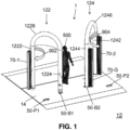
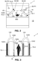
- FIG. 1 to 3 schematically illustrates, according to an exemplary embodiment, a front perspective view, a top view and a front view, respectively, of a gate in a vehicle blocking state.
- Fig. 1 illustrates the gate 1 comprising a first blocking element 122 and a second blocking element 124. Both first blocking element 122 and second blocking element 124 are configured to be placed on a surface 14. According to one embodiment, the first blocking element 122 is swivebly connected to the surface 14. According to another embodiment, the second blocking element 124 is swivebly connected to the surface 14. According to yet another embodiment, both the first blocking element 122 and the second blocking element 124 are swivebly connected to the surface 14. Any one of the two blocking elements is configured to swivel about a pivot axis.
- the gate as shown in the figures is placed on surface 14 wherein the surface 14 can be a base for the gate that is configured to be placed on the ground 12; however, in accordance with another embodiment, the gate is placed directly on the ground as defined above.
- the surface 14 is configured to be placed on the ground 12. According to yet another embodiment, the surface 14 is configured to be removably placed on the ground. According to still another embodiment, the surface 14 is configured to be permanently placed on the ground, for example by permanently connecting the surface to the ground.
- At least one of the first blocking element 122 and the second blocking element 124 are configured to be placed on the surface 14. According to another embodiment, at least one of the first blocking element 122 and the second blocking element 124 is configured to connect to the surface 14 in a way that the elements are swiveling about a pivoting axis.
- the surface 14 is a base mounted on the ground 12. Nevertheless, the illustration of the base serving as a surface 14 should not be considered as limiting the scope of the present subject matter.
- the surface 14 can be a ground as well.
- the first blocking element 122 comprises a first pole 1222 configured to be caught in the surface 14 and serve as a pivot axis of the first blocking element 122, and a second pole 1224 connected to the first pole 1222 with an upper connector 1226.
- the second blocking element 124 comprises a third pole 1242 configured to be caught in the surface 14 and serve as a pivot axis of the second blocking element 124, and a fourth pole 1244 connected to the third pole 1242 with an upper connector 1246.
- At least one of the first pole 1222 of the first blocking element 122 and the third pole 1242 of the second blocking element 124 is configured to be releasably caught in the surface 14. According to another embodiment, at least one of the first pole 1222 of the first blocking element 122 and the third pole 1242 of the second blocking element 124 is configured to be permanently caught in the surface 14.
- the upper connector 1226/1246 can have any shape, for example at least one of the upper connectors 1226/1246 is linear (not shown), or arched as shown for example in Fig. 1 , and the like.
- the upper connectors can be utilized also to different uses such as illumination.
- the upper connector is provided with an illuminating LEDS or other type of illuminator so as to provide light to the area of the gate.
- the upper connector can also be used for placing signposts indicating exit, directions, arrows, explanations, or the like.
- At least one of the blocking elements 122/124 is made of separate parts connected one to the other, namely a separate first/third pole 1222/1242, a separate second/fourth pole 1224/1244, and a separate upper connector 1226/1246 that are connected one to the other.
- at least one of the blocking elements 122/124 is made of one piece of material in a shape comprising the first/third pole 1222/1242, the second/fourth pole 1224/1244, and the upper connector 1226/1246.
- the first/third pole 1222/1242 and the upper connector 1226/1246 are made of one piece of material connected to the second/fourth pole 1224/1244.
- the second/fourth pole 1224/1244 and the upper connector 1226/1246 are made of one piece of material connected to the first/third pole 1222/1242.
- the first blocking element 122 is configured to allow passage of a pedestrian therethrough
- the second blocking element 124 is configured to allow passage of a pedestrian therethrough. This embodiment is achieved because a distance between the first/third pole 1222/1242 and the second/fourth pole 1224/1244, designated in Fig. 2 with dashed line 40, allows passage of a pedestrian therethrough (between the poles of a single blocking element).
- the first blocking element 122 is configured to block passage of a vehicle therethrough
- the second blocking element 124 is configured to block passage of a vehicle therethrough. This embodiment is achieved because the distance 40 between the first/third pole 1222/1242 and the second/fourth pole 1224/1244 blocks passage of a vehicle therethrough.
- the first blocking element 122 is configured to swivel about the first pole 1222, since the first pole 1222 serves as a first pivot axis of the first blocking element 122.
- the swivel movement that the first blocking element 122 is configured to perform is designated in Fig. 1 with arrow 902.
- the second blocking element 124 is configured to swivel about the third pole 1242, since the third pole 1242 serves as a second pivot axis of the second blocking element 124.
- the swivel movement that the second blocking element 124 is configured to perform is designated in Fig. 1 with arrow 904.
- the gate 1 is configured to be either in a vehicle blocking state or in a vehicle passage state. This embodiment is achieved by changing the orientation of the first blocking element 122 or the second blocking element 124, or both the first blocking element 122 and the second blocking element 124, one relative to the other while forming a gap therebetween.
- the gate 1 illustrated in Fig. 1 and in the following Figs. 2 and 3 is in a vehicle blocking state when the gap between the first blocking element and the second blocking element is set to be narrow enough to prevent passage of the vehicles.
- the gate 1 illustrated in Figs. 1-3 is in a vehicle blocking state.
- the orientation of the first blocking element 122 and the second blocking element 124 is such that a gap 30, illustrated with dashed line 30 in Fig. 2 , between the first blocking element 122 and the second blocking element 124 does not allow passage of a vehicle. Therefore, in the vehicle blocking state, the gate 1 blocks passage of a vehicle through the gate 1.
- the gap 30 between the poles of the first blocking element 122 and the second blocking element 124 allow passage of pedestrians 500.
- vehicles cannot pass through the gate since the poles are too close to each other, leaving only small gaps between them. These gaps allow people to pass through but not vehicles.
- At least one locking recess 50 for locking a blocking element 122/124 in a certain position, is made in the surface 14.
- an at least one locking recess 50 is made in the surface on which the gate 1 is placed.
- a second pole 1224/1244 of a blocking element 122/124 is configured to be locked in a locking recess 50, for example by inserting a lower end of the second pole 1224/1244 into the locking recess 50.
- the gate 1 can comprise either at least one locking recess 50-B 1 for locking the end of pole 1224, or at least one locking recess 50-B2 for locking the end of pole 1244; or both.
- the gate 1 is in a vehicle blocking state.
- the gap 30 between locking recess 50-B 1 for locking the first blocking element 124, and locking recess 50-B2 for locking the second blocking element 124 does not allow passage of a vehicle 600 (the vehicle is shown in Fig. 4 ).
- locking recess 50-B 1 and locking recess 50-B2 can be considered as locking recesses 50 for a vehicle blocking state of the gate 1.
- the recess can be also a full hole in the case that the surface is a base on the ground.
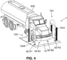
- FIG. 4-6 schematically illustrating, according to an exemplary embodiment, a front perspective view, a top view, and a frontal view, respectively, of a gate in a vehicle passage state and a vehicle passing through the gate.
- the gate 1 illustrated in Figs. 4 - 6 is in a vehicle passage state.
- the orientation of the first blocking element 122 and the second blocking element 124 is such that the gap 30 (indicated in Fig. 5 ) between the first blocking element 122 and the second blocking element 124 allow passage of a vehicle 600.
- the blocking elements 122 and 124 are oriented in a position in which they are substantially parallel to one another and the gap between them is maximal while no poles are situated within the gap 30. Movement of vehicles through the gate is allowed when the gap is set to be broad enough. Therefore, in the vehicle passage state, the gate 1 allows passage of a vehicle through the gate 1. Needless to mention that in the vehicle passage state, the gate 1 also allows passage of pedestrians through the gap 30 between the first blocking element 122 and the second blocking element 124.
- the gate 1 comprises either a locking recess 50-PI for locking the lower end of pole 1224 of the first blocking element 122, or/and a locking recess 50-P2 for locking the lower end of pole 1244 of the second blocking element 124.
- a locking recess 50-PI for locking the lower end of pole 1224 of the first blocking element 122
- a locking recess 50-P2 for locking the lower end of pole 1244 of the second blocking element 124.
- locking recess 50-PI and locking recess 50-P2 can be considered as locking recess 50 for a vehicle passage state of the gate 1.
- the gate 1 can comprise any number of locking holes 50 either for the first blocking element 122, or the second blocking element 124, or both the first blocking element 122 and the second blocking element 124.
- the orientation of the first blocking element 122 and the second blocking element 124, with or without locking holes 50 can be any orientation that can be deemed useful or necessary to the circumstances and conditions in which the gate 1 is used.
- the blocking element 122/124 is configured to be permanently locked by the at least one locking recess 50. According to another embodiment, the blocking element 122/124 is configured to be releasably locked by the at least one locking recess 50.
- the first blocking element 122 is configured to be permanently locked by locking recess 50-PI, while the second blocking element 124 is configured to be releasably locked by locking recess 50-P2.
- the first blocking element 122 is configured to be releasably locked by locking recess 50-PI, while the second blocking element 124 is configured to be permanently locked by locking recess 50-P2.
- both the first blocking element 122 is configured to be permanently locked by locking recess 50-PI and the second blocking element 124 is configured to be permanently locked by locking recess 50-P2.
- the gate 1 can be either in a vehicle blocking state, or a vehicle passage state, depending on the gap 30 between the first blocking element 122 and the second blocking element 124.
- the gate 1 further comprises at least one shutter 70 configured to block passage of pedestrians through the gate 1 (the indication of the different shutters shown in the figures is by an extension to the number 70, such as 70-1, 70-2, and 70-G).
- Shutters 70-1 and 70-2 are configured to block passage of pedestrians through a blocking element 122/124.
- Shutter 70-G is configured to block passage of pedestrians through the gap 30 between the first blocking element 122 and the second blocking element 124.
- the gate 1 comprises a first shutter 70-1 configured to block passage of pedestrians through the first blocking element 122 and/or a second shutter 70-2 configured to block passage of pedestrians through the second blocking element 122 and/or. a gap shutter 70-G configured to block passage of pedestrians through the gap 30 between the first blocking element 122 and the second blocking element 124.
- the shutter 70 is configured to be in an open state - allowing passage of pedestrians.
- the shutter 70 is configured to be in a closed state - blocking passage of pedestrians. Any mechanism known in the art that allows the shutter 70 to be in an open state or a closed state is under the scope of the present subject matter, for example, when the shutter 70 is in a form of a foldable mesh folding and opening aside, in a form of a rolling shutter folding and opening up and down, in a form of a door pivotally connected to one of the poles, and the like.
- the closed state the shutter 70 blocks passage of pedestrians.
- the shutter 70 allows passage of pedestrians.
- the first shutter 70-1, the second shutter 70-2 and the gap shutter 70-G are independent, namely each one of the shutters 70 can be in a closed state or in an open state independently of the other shutters 70 of the gate 1.
- any type of shutter 70 known in the art is under the scope of the present subject matter. It should be noted that the following examples of a shutter 70 should not be considered as limiting the scope of the present subject matter.
- the shutter 70 is a roll-up shutter 70.
- the roll-up shutter attached to an upper part of the first blocking element 122, or of the second blocking element 124, or both the first blocking element 122 and the second blocking element 124.
- the roll-up shutter 70 is attached to the blocking element 122/124 in the vicinity of the upper connector 1226/1246.
- Another exemplary shutter 70 is a shutter 70 pivotally attached to one of the poles of a blocking element 122/124. This type of shutter is configured to open and close by swiveling about the pole of the pole to which the shutter 70 is attached.
- FIG. 70 another exemplary shutter 70 is a foldable mesh shutter 70 or in other words - garmoshka-like shutter 70.
- This type of shutter 70 is described herein and illustrated in the accompanying drawings, but as stated above, it is described only as an exemplary type of shutter 70.
- the foldable mesh shutter 70 is attached to one of the poles of a blocking element.
- the first foldable mesh shutter 70-1 is attached to the first pole 1222 of the first blocking element 122.
- the first foldable mesh shutter 70-1 is attached to the second pole 1223 of the first blocking element 122 (not shown).
- the second foldable mesh shutter 70-2 is attached to the third pole 1242 of the second blocking element 124.
- the second foldable mesh shutter 70-2 is attached to the second pole 1244 of the second blocking element (not seen).
- the gap foldable mesh shutter 70-G is attached to the fourth pole 1244 of the second blocking element 124.
- the gap shutter 70-G is attached to the second pole 1224 of the first blocking element 122.
- the foldable mesh shutter 70 can comprise a first shutter part and a second shutter part, each shutter part is attached to a different pole of a blocking element 122/124.
- bringing the shutter 70 to a closed state can be performed, for example, by approximating the first shutter part and the second shutter part one to the other, and connecting the first shutter part and the second shutter part one to the other in a manner that prevents passage of pedestrians through the gap that is now blocked by the first shutter part and the second shutter part.
- Figs. 1-3 illustrate the first shutter 70-1, the second shutter 70-2 and the gap shutter 70- G in an open state, allowing passage of pedestrians.
- FIG. 7 schematically illustrating, according to an exemplary embodiment, a front perspective view of a gate in a vehicle blocking state, while the shutters of the gate are in a closed state.
- Fig. 7 illustrates a gate 1 comprising shutters 70 in a closed state, configured to prevent passage of pedestrians.
- a shutter 70 in the form of a foldable mesh the shutter 70 is folded in the open state, as illustrated for example in Figs. 1-3 .
- the closed state as illustrated in Fig. 7 , the shutter 70 is unfolded and blocks passage of pedestrians.
- an edge of the shutter 70 in the form of a foldable mesh is attached to an opposite pole in relation to the pole to which the shutter is attached.
- the gate 1 of the present subject matter can be in of three states: a vehicle blocking and pedestrians passage state, as illustrated in Figs. 1-3 ; a vehicle and pedestrians passage state, as illustrated in Figs. 4-6 ; and a vehicle and pedestrians blocking state, as illustrated in Fig. 7 .
Landscapes
- Engineering & Computer Science (AREA)
- Civil Engineering (AREA)
- Structural Engineering (AREA)
- Architecture (AREA)
- Refuge Islands, Traffic Blockers, Or Guard Fence (AREA)
Claims (13)
- Portail (1) permettant de contrôler le passage de véhicules comprenant:au moins un premier élément de blocage (122) configuré pour pivoter autour d'un premier axe de pivotement; etau moins un deuxième élément de blocage (124) configuré pour pivoter autour d'un deuxième axe de pivotement;dans lequel le premier élément de blocage (122) et le deuxième élément de blocage (124) sont configurés pour pivoter l'un en face de l'autre de sorte qu'un espace (30) se forme entre le premier élément de blocage (122) et le deuxième élément de blocage (122), et dans lequel l'espace (30) est réglé pour permettre ou bloquer le passage des véhicules à travers l'espace (30);dans lequel le premier élément de blocage (122) comprend un premier poteau (1222) configuré pour servir de premier axe de pivotement pour le premier élément de blocage (122), et un deuxième poteau (1224) connecté au premier poteau (1222) avec un connecteur supérieur (1226),dans lequel le deuxième élément de blocage (124) comprend un troisième poteau (1242) configuré pour servir de deuxième axe de pivotement pour le deuxième élément de blocage (124), et un quatrième poteau (1244) connecté au troisième poteau (1242) avec un connecteur supérieur (1246),caractérisé parau moins un volet (70-1; 70-2; 70-G) configuré pour bloquer le passage des piétons au moyen du premier élément de blocage (122), au moyen du deuxième élément de blocage (124) ou au moyen de l'espace (30) lorsque le volet est à l'état fermé.
- Portail selon la revendication 1, dans lequel le premier élément de blocage (122) et le deuxième élément de blocage (124) sont configurés pour être placés de manière amovible sur une surface ou placés de manière permanente sur la surface (14).
- Portail selon la revendication 2, dans lequel la surface (14) est une base configurée pour être placée sur le sol (12), et dans lequel la base est configurée pour être placée de manière amovible sur le sol (12) ou être placée de manière permanente sur le sol (12).
- Portail selon l'une des revendications 1 à 3, dans lequel l'espace (30) se trouve entre le deuxième poteau (1224) et le quatrième poteau (1224).
- Portail selon la revendication 4, dans lequel au moins l'un parmi le premier poteau du premier élément de blocage (1222) et le troisième poteau (1242) du deuxième élément de blocage est configuré pour être coincé de manière amovible dans la surface (14) ou être coincé de manière permanente dans la surface (14).
- Portail selon l'une quelconque des revendications 1 à 5, dans lequel au moins un des connecteurs supérieurs (126, 1246) est linéaire ou arqué.
- Portail selon l'une quelconque des revendications 1 à 6, dans lequel au moins un des éléments de blocage (122, 124) est constitué d'un premier ou d'un troisième poteau séparé (1222, 1242), d'un deuxième poteau ou d'un quatrième poteau séparé (1224, 1244), respectivement, et d'un connecteur supérieur séparé (1226, 1246), qui sont connectés les uns aux autres.
- Portail selon l'une quelconque des revendications 1 à 6, dans lequel au moins un des éléments de blocage (122, 124) est constitué d'une seule pièce de matériau dont la forme comprend respectivement le premier poteau ou le troisième poteau (1222, 1242), le deuxième poteau ou le quatrième poteau (1224, 1244), et le connecteur supérieur (1226, 1246).
- Portail selon l'une quelconque des revendications 1 à 6, dans lequel au moins l'un parmi les éléments de blocage (122, 124), le premier poteau ou le troisième poteau (1222, 1242), et le connecteur supérieur (1226, 1246) sont constitués d'une seule pièce de matériau connectée respectivement au deuxième poteau ou au quatrième poteau (1226, 1246).
- Portail selon l'une quelconque des revendications 1 à 6, dans lequel au moins l'un parmi les éléments de blocage (122, 124), le deuxième poteau ou le quatrième poteau (1224, 1244) et le connecteur supérieur (1226, 1246) sont constitués d'une seule pièce de matériau connectée respectivement au premier poteau ou au troisième poteau (1222, 1242).
- Portail selon l'une quelconque des revendications 1 à 10, dans lequel le portail (1) est configurée pour être soit dans un état de blocage de véhicule, soit dans un état de passage de véhicule et dans lequel le portail est dans un état de blocage de véhicule lorsque l'espace (30) entre le premier élément de blocage (122) et le deuxième élément de blocage (124) est réglé pour être suffisamment étroit pour empêcher le passage des véhicules, et dans lequel le mouvement des véhicules à travers le portail est autorisé lorsque l'espace (30) est réglé pour être suffisamment large.
- Portail selon l'une quelconque des revendications 1 à 11, comprenant en outre au moins un évidement de verrouillage (50) pour verrouiller une extrémité inférieure d'au moins un élément de blocage (122, 124) qui pivote autour de l'axe de pivotement.
- Portail selon l'une quelconque des revendications 1 à 12, dans lequel le volt (70-1; 70-2; 70-G) est un volet roulant.
Applications Claiming Priority (2)
| Application Number | Priority Date | Filing Date | Title |
|---|---|---|---|
| US201962787791P | 2019-01-03 | 2019-01-03 | |
| PCT/IB2020/050010 WO2020141471A1 (fr) | 2019-01-03 | 2020-01-02 | Barrière |
Publications (3)
| Publication Number | Publication Date |
|---|---|
| EP3906342A1 EP3906342A1 (fr) | 2021-11-10 |
| EP3906342A4 EP3906342A4 (fr) | 2022-09-07 |
| EP3906342B1 true EP3906342B1 (fr) | 2024-12-11 |
Family
ID=71407007
Family Applications (1)
| Application Number | Title | Priority Date | Filing Date |
|---|---|---|---|
| EP20736151.0A Active EP3906342B1 (fr) | 2019-01-03 | 2020-01-02 | Barrière |
Country Status (8)
| Country | Link |
|---|---|
| US (1) | US12139863B2 (fr) |
| EP (1) | EP3906342B1 (fr) |
| ES (1) | ES3009696T3 (fr) |
| FI (1) | FI3906342T3 (fr) |
| HU (1) | HUE069857T2 (fr) |
| IL (1) | IL284568A (fr) |
| PL (1) | PL3906342T3 (fr) |
| WO (1) | WO2020141471A1 (fr) |
Families Citing this family (3)
| Publication number | Priority date | Publication date | Assignee | Title |
|---|---|---|---|---|
| WO2020144612A1 (fr) | 2019-01-09 | 2020-07-16 | Klein Amos | Barrière pliable et système comprenant celle-ci |
| US12416124B2 (en) | 2019-02-28 | 2025-09-16 | Amos Klein | Dissecting barrier |
| WO2020222156A1 (fr) | 2019-04-30 | 2020-11-05 | Klein Amos | Barrière de jersey télescopique |
Family Cites Families (23)
| Publication number | Priority date | Publication date | Assignee | Title |
|---|---|---|---|---|
| US1651221A (en) * | 1927-01-31 | 1927-11-29 | George T O'maley | Highway barrier |
| US2137193A (en) * | 1936-04-03 | 1938-11-15 | Stafford John Conrad | Traffic control gate |
| ES285601Y (es) * | 1985-03-25 | 1987-04-16 | Progesco,S.A. | Dispositivo para el bloqueo de plazas de aparcamiento de ve-hiculos |
| US4759655A (en) * | 1987-06-16 | 1988-07-26 | Flexible Barricades Inc. | Terrorist vehicle arresting system |
| US4923327A (en) * | 1987-12-04 | 1990-05-08 | Flexible Barricades, Inc. | Terrorist vehicle arresting system |
| JP2503260Y2 (ja) * | 1991-11-01 | 1996-06-26 | トーア・スチール株式会社 | 車止め |
| US6155744A (en) * | 1999-01-07 | 2000-12-05 | Namanny; Kenneth D. | Parking management system |
| US6733204B1 (en) * | 2002-08-07 | 2004-05-11 | Ronald F. Paniccia | View shield device |
| FR2854413B1 (fr) | 2003-04-30 | 2005-06-17 | Da Silva Soc D Expl Des Ets | Barriere de securite |
| GB2403251A (en) * | 2003-06-27 | 2004-12-29 | Kevin Behan | Security barrier for stopping vehicles |
| WO2005049925A1 (fr) * | 2003-11-18 | 2005-06-02 | Safecross Pty Ltd | Appareil portable a barriere pivotante |
| US7217061B2 (en) * | 2005-07-19 | 2007-05-15 | Ves Industries, L.L.C. | Barrier system |
| GB2430964A (en) * | 2005-07-29 | 2007-04-11 | Agrid Fencing Ltd | Barrier for preventing the passage of vehicles other than disabled vehicles |
| US7862252B2 (en) * | 2006-04-10 | 2011-01-04 | Universal Safety Response, Inc. | Vehicle barrier system |
| US8001880B2 (en) * | 2007-05-04 | 2011-08-23 | Defenshield, Inc. | Barrier |
| US7818920B2 (en) * | 2007-11-06 | 2010-10-26 | Causey Lynn R | Barrier gate with torque limiter |
| US7524135B1 (en) * | 2008-06-06 | 2009-04-28 | Schram Management Company | Post assembly and method of assembling the same |
| US7600554B1 (en) * | 2008-06-12 | 2009-10-13 | Felicia M Wright | Portable accident barrier |
| CA2956644C (fr) * | 2011-02-11 | 2019-01-29 | Traffix Devices, Inc. | Traitements d'extremite et transitions pour series de barrieres de protection remplies d'eau |
| US8905671B2 (en) * | 2013-03-08 | 2014-12-09 | John Weatherwax | High speed raceway barrier |
| US9096978B2 (en) * | 2013-10-28 | 2015-08-04 | Black Bart, Inc. | Expandable roadside safety apparatus |
| DE202013010383U1 (de) * | 2013-11-15 | 2014-01-17 | Magnetic Autocontrol Gmbh | Schrankenanlage |
| GB2538116A (en) | 2015-09-28 | 2016-11-09 | Integrated Design Ltd | Floor protector |
-
2020
- 2020-01-02 US US17/420,273 patent/US12139863B2/en active Active
- 2020-01-02 HU HUE20736151A patent/HUE069857T2/hu unknown
- 2020-01-02 ES ES20736151T patent/ES3009696T3/es active Active
- 2020-01-02 WO PCT/IB2020/050010 patent/WO2020141471A1/fr not_active Ceased
- 2020-01-02 PL PL20736151.0T patent/PL3906342T3/pl unknown
- 2020-01-02 FI FIEP20736151.0T patent/FI3906342T3/fi active
- 2020-01-02 EP EP20736151.0A patent/EP3906342B1/fr active Active
-
2021
- 2021-07-01 IL IL284568A patent/IL284568A/en unknown
Also Published As
| Publication number | Publication date |
|---|---|
| IL284568A (en) | 2021-08-31 |
| US20220090336A1 (en) | 2022-03-24 |
| WO2020141471A1 (fr) | 2020-07-09 |
| PL3906342T3 (pl) | 2025-05-12 |
| EP3906342A1 (fr) | 2021-11-10 |
| HUE069857T2 (hu) | 2025-04-28 |
| FI3906342T3 (fi) | 2025-01-28 |
| EP3906342A4 (fr) | 2022-09-07 |
| ES3009696T3 (en) | 2025-03-31 |
| US12139863B2 (en) | 2024-11-12 |
Similar Documents
| Publication | Publication Date | Title |
|---|---|---|
| EP3906342B1 (fr) | Barrière | |
| US5149061A (en) | Panel for road construction | |
| CA2532554C (fr) | Systeme d'alignement de delineateur de circulation | |
| KR200452739Y1 (ko) | 로드킬차단가드레일 | |
| NL1031381C2 (nl) | Road Blocker/Wegversperring. | |
| Luoma et al. | Effects of experience with retroreflectors on recognition of nighttime pedestrians: comparison of driver performance in Finland and Michigan | |
| WO2009055875A1 (fr) | Cache temporaire de panneau de signalisation | |
| FR2646456A1 (fr) | Installation d'abri pour pietons | |
| KR102385140B1 (ko) | 트랩형 노면 경전철 도로용 안전 난간 | |
| US20080213041A1 (en) | Traffic barricade having interchangeable parts | |
| JP2013110967A (ja) | 小動物侵入防止構造 | |
| RU2278198C1 (ru) | Заградитель для автотранспорта | |
| KR200244680Y1 (ko) | 차량 높이 제한장치 | |
| US20060216111A1 (en) | Two-level continuous flow crossroad and construction method and prefabricated parts thereof | |
| DE202004019751U1 (de) | Vorrichtung zum Schutz vor Wildwechsel auf befahrenen Straßen | |
| EP0128897A1 (fr) | Organe de jupe pour une barriere de passage a niveau | |
| KR100638530B1 (ko) | 고정브라켓 | |
| KR100969809B1 (ko) | 접이식 볼라드 | |
| KR200430471Y1 (ko) | 사슬을 장착한 차선규제 가이드박스 | |
| KR200412234Y1 (ko) | 안전 경계봉 | |
| KR101222074B1 (ko) | 일방향 통로 구조체 | |
| KR200215327Y1 (ko) | 햇빛 차단 장치가 있는 신호등 | |
| KR20250068218A (ko) | 분리 가능한 횡단보도용 교통 신호기 | |
| KR100532781B1 (ko) | 저장용기 탑재가 가능한 도로용 경계블럭 | |
| KR101181544B1 (ko) | 가드펜스 |
Legal Events
| Date | Code | Title | Description |
|---|---|---|---|
| STAA | Information on the status of an ep patent application or granted ep patent |
Free format text: STATUS: THE INTERNATIONAL PUBLICATION HAS BEEN MADE |
|
| PUAI | Public reference made under article 153(3) epc to a published international application that has entered the european phase |
Free format text: ORIGINAL CODE: 0009012 |
|
| STAA | Information on the status of an ep patent application or granted ep patent |
Free format text: STATUS: REQUEST FOR EXAMINATION WAS MADE |
|
| 17P | Request for examination filed |
Effective date: 20210802 |
|
| AK | Designated contracting states |
Kind code of ref document: A1 Designated state(s): AL AT BE BG CH CY CZ DE DK EE ES FI FR GB GR HR HU IE IS IT LI LT LU LV MC MK MT NL NO PL PT RO RS SE SI SK SM TR |
|
| DAV | Request for validation of the european patent (deleted) | ||
| DAX | Request for extension of the european patent (deleted) | ||
| A4 | Supplementary search report drawn up and despatched |
Effective date: 20220810 |
|
| RIC1 | Information provided on ipc code assigned before grant |
Ipc: E06B 11/00 20060101ALI20220804BHEP Ipc: E01F 13/06 20060101AFI20220804BHEP |
|
| GRAP | Despatch of communication of intention to grant a patent |
Free format text: ORIGINAL CODE: EPIDOSNIGR1 |
|
| STAA | Information on the status of an ep patent application or granted ep patent |
Free format text: STATUS: GRANT OF PATENT IS INTENDED |
|
| INTG | Intention to grant announced |
Effective date: 20240709 |
|
| GRAS | Grant fee paid |
Free format text: ORIGINAL CODE: EPIDOSNIGR3 |
|
| GRAA | (expected) grant |
Free format text: ORIGINAL CODE: 0009210 |
|
| STAA | Information on the status of an ep patent application or granted ep patent |
Free format text: STATUS: THE PATENT HAS BEEN GRANTED |
|
| AK | Designated contracting states |
Kind code of ref document: B1 Designated state(s): AL AT BE BG CH CY CZ DE DK EE ES FI FR GB GR HR HU IE IS IT LI LT LU LV MC MK MT NL NO PL PT RO RS SE SI SK SM TR |
|
| REG | Reference to a national code |
Ref country code: GB Ref legal event code: FG4D |
|
| REG | Reference to a national code |
Ref country code: CH Ref legal event code: EP |
|
| REG | Reference to a national code |
Ref country code: IE Ref legal event code: FG4D |
|
| REG | Reference to a national code |
Ref country code: DE Ref legal event code: R096 Ref document number: 602020042948 Country of ref document: DE |
|
| REG | Reference to a national code |
Ref country code: FI Ref legal event code: FGE |
|
| REG | Reference to a national code |
Ref country code: NL Ref legal event code: FP |
|
| REG | Reference to a national code |
Ref country code: SE Ref legal event code: TRGR |
|
| REG | Reference to a national code |
Ref country code: ES Ref legal event code: FG2A Ref document number: 3009696 Country of ref document: ES Kind code of ref document: T3 Effective date: 20250331 |
|
| REG | Reference to a national code |
Ref country code: LT Ref legal event code: MG9D |
|
| PG25 | Lapsed in a contracting state [announced via postgrant information from national office to epo] |
Ref country code: HR Free format text: LAPSE BECAUSE OF FAILURE TO SUBMIT A TRANSLATION OF THE DESCRIPTION OR TO PAY THE FEE WITHIN THE PRESCRIBED TIME-LIMIT Effective date: 20241211 |
|
| PG25 | Lapsed in a contracting state [announced via postgrant information from national office to epo] |
Ref country code: BG Free format text: LAPSE BECAUSE OF FAILURE TO SUBMIT A TRANSLATION OF THE DESCRIPTION OR TO PAY THE FEE WITHIN THE PRESCRIBED TIME-LIMIT Effective date: 20241211 |
|
| PG25 | Lapsed in a contracting state [announced via postgrant information from national office to epo] |
Ref country code: GR Free format text: LAPSE BECAUSE OF FAILURE TO SUBMIT A TRANSLATION OF THE DESCRIPTION OR TO PAY THE FEE WITHIN THE PRESCRIBED TIME-LIMIT Effective date: 20250312 Ref country code: LV Free format text: LAPSE BECAUSE OF FAILURE TO SUBMIT A TRANSLATION OF THE DESCRIPTION OR TO PAY THE FEE WITHIN THE PRESCRIBED TIME-LIMIT Effective date: 20241211 |
|
| REG | Reference to a national code |
Ref country code: HU Ref legal event code: AG4A Ref document number: E069857 Country of ref document: HU |
|
| PG25 | Lapsed in a contracting state [announced via postgrant information from national office to epo] |
Ref country code: RS Free format text: LAPSE BECAUSE OF FAILURE TO SUBMIT A TRANSLATION OF THE DESCRIPTION OR TO PAY THE FEE WITHIN THE PRESCRIBED TIME-LIMIT Effective date: 20250311 |
|
| REG | Reference to a national code |
Ref country code: AT Ref legal event code: MK05 Ref document number: 1750473 Country of ref document: AT Kind code of ref document: T Effective date: 20241211 |
|
| PG25 | Lapsed in a contracting state [announced via postgrant information from national office to epo] |
Ref country code: SM Free format text: LAPSE BECAUSE OF FAILURE TO SUBMIT A TRANSLATION OF THE DESCRIPTION OR TO PAY THE FEE WITHIN THE PRESCRIBED TIME-LIMIT Effective date: 20241211 |
|
| PG25 | Lapsed in a contracting state [announced via postgrant information from national office to epo] |
Ref country code: IS Free format text: LAPSE BECAUSE OF FAILURE TO SUBMIT A TRANSLATION OF THE DESCRIPTION OR TO PAY THE FEE WITHIN THE PRESCRIBED TIME-LIMIT Effective date: 20250411 |
|
| PG25 | Lapsed in a contracting state [announced via postgrant information from national office to epo] |
Ref country code: PT Free format text: LAPSE BECAUSE OF FAILURE TO SUBMIT A TRANSLATION OF THE DESCRIPTION OR TO PAY THE FEE WITHIN THE PRESCRIBED TIME-LIMIT Effective date: 20250411 |
|
| PG25 | Lapsed in a contracting state [announced via postgrant information from national office to epo] |
Ref country code: EE Free format text: LAPSE BECAUSE OF FAILURE TO SUBMIT A TRANSLATION OF THE DESCRIPTION OR TO PAY THE FEE WITHIN THE PRESCRIBED TIME-LIMIT Effective date: 20241211 |
|
| PG25 | Lapsed in a contracting state [announced via postgrant information from national office to epo] |
Ref country code: AT Free format text: LAPSE BECAUSE OF FAILURE TO SUBMIT A TRANSLATION OF THE DESCRIPTION OR TO PAY THE FEE WITHIN THE PRESCRIBED TIME-LIMIT Effective date: 20241211 Ref country code: RO Free format text: LAPSE BECAUSE OF FAILURE TO SUBMIT A TRANSLATION OF THE DESCRIPTION OR TO PAY THE FEE WITHIN THE PRESCRIBED TIME-LIMIT Effective date: 20241211 |
|
| PG25 | Lapsed in a contracting state [announced via postgrant information from national office to epo] |
Ref country code: SK Free format text: LAPSE BECAUSE OF FAILURE TO SUBMIT A TRANSLATION OF THE DESCRIPTION OR TO PAY THE FEE WITHIN THE PRESCRIBED TIME-LIMIT Effective date: 20241211 |
|
| PG25 | Lapsed in a contracting state [announced via postgrant information from national office to epo] |
Ref country code: CZ Free format text: LAPSE BECAUSE OF FAILURE TO SUBMIT A TRANSLATION OF THE DESCRIPTION OR TO PAY THE FEE WITHIN THE PRESCRIBED TIME-LIMIT Effective date: 20241211 |
|
| REG | Reference to a national code |
Ref country code: DE Ref legal event code: R097 Ref document number: 602020042948 Country of ref document: DE |
|
| PG25 | Lapsed in a contracting state [announced via postgrant information from national office to epo] |
Ref country code: LU Free format text: LAPSE BECAUSE OF NON-PAYMENT OF DUE FEES Effective date: 20250102 |
|
| PG25 | Lapsed in a contracting state [announced via postgrant information from national office to epo] |
Ref country code: DK Free format text: LAPSE BECAUSE OF FAILURE TO SUBMIT A TRANSLATION OF THE DESCRIPTION OR TO PAY THE FEE WITHIN THE PRESCRIBED TIME-LIMIT Effective date: 20241211 |
|
| PLBE | No opposition filed within time limit |
Free format text: ORIGINAL CODE: 0009261 |
|
| STAA | Information on the status of an ep patent application or granted ep patent |
Free format text: STATUS: NO OPPOSITION FILED WITHIN TIME LIMIT |
|
| REG | Reference to a national code |
Ref country code: CH Ref legal event code: L10 Free format text: ST27 STATUS EVENT CODE: U-0-0-L10-L00 (AS PROVIDED BY THE NATIONAL OFFICE) Effective date: 20251022 |
|
| 26N | No opposition filed |
Effective date: 20250912 |
|
| PGFP | Annual fee paid to national office [announced via postgrant information from national office to epo] |
Ref country code: GB Payment date: 20251218 Year of fee payment: 7 |
|
| PG25 | Lapsed in a contracting state [announced via postgrant information from national office to epo] |
Ref country code: IE Free format text: LAPSE BECAUSE OF NON-PAYMENT OF DUE FEES Effective date: 20250102 |
|
| PGFP | Annual fee paid to national office [announced via postgrant information from national office to epo] |
Ref country code: PL Payment date: 20251222 Year of fee payment: 7 |
|
| REG | Reference to a national code |
Ref country code: CH Ref legal event code: U11 Free format text: ST27 STATUS EVENT CODE: U-0-0-U10-U11 (AS PROVIDED BY THE NATIONAL OFFICE) Effective date: 20260201 |
|
| PGFP | Annual fee paid to national office [announced via postgrant information from national office to epo] |
Ref country code: NL Payment date: 20260112 Year of fee payment: 7 |
|
| PGFP | Annual fee paid to national office [announced via postgrant information from national office to epo] |
Ref country code: HU Payment date: 20251230 Year of fee payment: 7 |
|
| PGFP | Annual fee paid to national office [announced via postgrant information from national office to epo] |
Ref country code: SE Payment date: 20260119 Year of fee payment: 7 |
|
| PGFP | Annual fee paid to national office [announced via postgrant information from national office to epo] |
Ref country code: ES Payment date: 20260201 Year of fee payment: 7 Ref country code: MC Payment date: 20260119 Year of fee payment: 7 |
|
| PGFP | Annual fee paid to national office [announced via postgrant information from national office to epo] |
Ref country code: NO Payment date: 20260121 Year of fee payment: 7 Ref country code: DE Payment date: 20260112 Year of fee payment: 7 |
|
| PGFP | Annual fee paid to national office [announced via postgrant information from national office to epo] |
Ref country code: FI Payment date: 20260112 Year of fee payment: 7 Ref country code: BE Payment date: 20260112 Year of fee payment: 7 Ref country code: IT Payment date: 20260112 Year of fee payment: 7 |
|
| PGFP | Annual fee paid to national office [announced via postgrant information from national office to epo] |
Ref country code: FR Payment date: 20260119 Year of fee payment: 7 |
|
| PGFP | Annual fee paid to national office [announced via postgrant information from national office to epo] |
Ref country code: TR Payment date: 20260102 Year of fee payment: 7 |
|
| PGFP | Annual fee paid to national office [announced via postgrant information from national office to epo] |
Ref country code: CH Payment date: 20260201 Year of fee payment: 7 |