EP3906830A1 - Handgeführter zyklon-staubsauger - Google Patents
Handgeführter zyklon-staubsauger Download PDFInfo
- Publication number
- EP3906830A1 EP3906830A1 EP21169274.4A EP21169274A EP3906830A1 EP 3906830 A1 EP3906830 A1 EP 3906830A1 EP 21169274 A EP21169274 A EP 21169274A EP 3906830 A1 EP3906830 A1 EP 3906830A1
- Authority
- EP
- European Patent Office
- Prior art keywords
- filter stage
- drive unit
- filter
- vacuum cleaner
- container
- Prior art date
- Legal status (The legal status is an assumption and is not a legal conclusion. Google has not performed a legal analysis and makes no representation as to the accuracy of the status listed.)
- Granted
Links
Images

Classifications
-
- A—HUMAN NECESSITIES
- A47—FURNITURE; DOMESTIC ARTICLES OR APPLIANCES; COFFEE MILLS; SPICE MILLS; SUCTION CLEANERS IN GENERAL
- A47L—DOMESTIC WASHING OR CLEANING; SUCTION CLEANERS IN GENERAL
- A47L5/00—Structural features of suction cleaners
- A47L5/12—Structural features of suction cleaners with power-driven air-pumps or air-compressors, e.g. driven by motor vehicle engine vacuum
- A47L5/22—Structural features of suction cleaners with power-driven air-pumps or air-compressors, e.g. driven by motor vehicle engine vacuum with rotary fans
- A47L5/24—Hand-supported suction cleaners
-
- A—HUMAN NECESSITIES
- A47—FURNITURE; DOMESTIC ARTICLES OR APPLIANCES; COFFEE MILLS; SPICE MILLS; SUCTION CLEANERS IN GENERAL
- A47L—DOMESTIC WASHING OR CLEANING; SUCTION CLEANERS IN GENERAL
- A47L9/00—Details or accessories of suction cleaners, e.g. mechanical means for controlling the suction or for effecting pulsating action; Storing devices specially adapted to suction cleaners or parts thereof; Carrying-vehicles specially adapted for suction cleaners
- A47L9/10—Filters; Dust separators; Dust removal; Automatic exchange of filters
- A47L9/12—Dry filters
- A47L9/122—Dry filters flat
-
- A—HUMAN NECESSITIES
- A47—FURNITURE; DOMESTIC ARTICLES OR APPLIANCES; COFFEE MILLS; SPICE MILLS; SUCTION CLEANERS IN GENERAL
- A47L—DOMESTIC WASHING OR CLEANING; SUCTION CLEANERS IN GENERAL
- A47L9/00—Details or accessories of suction cleaners, e.g. mechanical means for controlling the suction or for effecting pulsating action; Storing devices specially adapted to suction cleaners or parts thereof; Carrying-vehicles specially adapted for suction cleaners
- A47L9/10—Filters; Dust separators; Dust removal; Automatic exchange of filters
- A47L9/12—Dry filters
- A47L9/127—Dry filters tube- or sleeve-shaped
-
- A—HUMAN NECESSITIES
- A47—FURNITURE; DOMESTIC ARTICLES OR APPLIANCES; COFFEE MILLS; SPICE MILLS; SUCTION CLEANERS IN GENERAL
- A47L—DOMESTIC WASHING OR CLEANING; SUCTION CLEANERS IN GENERAL
- A47L9/00—Details or accessories of suction cleaners, e.g. mechanical means for controlling the suction or for effecting pulsating action; Storing devices specially adapted to suction cleaners or parts thereof; Carrying-vehicles specially adapted for suction cleaners
- A47L9/10—Filters; Dust separators; Dust removal; Automatic exchange of filters
- A47L9/16—Arrangement or disposition of cyclones or other devices with centrifugal action
- A47L9/1658—Construction of outlets
- A47L9/1666—Construction of outlets with filtering means
-
- A—HUMAN NECESSITIES
- A47—FURNITURE; DOMESTIC ARTICLES OR APPLIANCES; COFFEE MILLS; SPICE MILLS; SUCTION CLEANERS IN GENERAL
- A47L—DOMESTIC WASHING OR CLEANING; SUCTION CLEANERS IN GENERAL
- A47L9/00—Details or accessories of suction cleaners, e.g. mechanical means for controlling the suction or for effecting pulsating action; Storing devices specially adapted to suction cleaners or parts thereof; Carrying-vehicles specially adapted for suction cleaners
- A47L9/22—Mountings for motor fan assemblies
Definitions
- the invention relates to a hand-held cyclone vacuum cleaner which, for the sake of simplicity, is referred to below as a vacuum cleaner.
- the invention relates to a vacuum cleaner which has a separating container for receiving suction material and a drive unit container which has a drive unit which is designed to generate a suction air flow during operation.
- Such a vacuum cleaner is from the WO2017 / 046 559 A1 known.
- the vacuum cleaner has two filter stages that are implemented using cyclone technology so that they are designed as a multi-cyclone. Furthermore, the vacuum cleaner has a third filter stage downstream of the multicyclone in terms of flow, which is built around an encapsulated radial fan. An axial outflow of the fan is directed through an exhaust air filter.
- the flow to the various filter stages requires a relatively large amount of space.
- the invention thus poses the problem of providing a hand-held cyclone vacuum cleaner which has several filter stages that are implemented in a compact installation space.
- the filter levels should be accessible to the user.
- the invention provides a vacuum cleaner in a compact design which has several filter stages.
- the implementation of several filter stages enables a particularly effective separation unit with a first filter stage with a particularly sharp separation.
- all filter stages of the separation unit that require periodic cleaning are arranged to be easily accessible for the user.
- the invention relates to a hand-held cyclone vacuum cleaner, having a separation unit for collecting suction material, which has a drive unit for generating a suction flow, a first filter stage, a second filter stage and a third filter stage; wherein the drive unit is arranged in a drive unit housing downstream of the second filter stage and upstream of the third filter stage, the drive unit being flowed around by the suction flow generated when the drive unit is in operation.
- the drive unit is spatially arranged between the second filter stage and the third filter stage in a drive unit housing.
- suction flow can flow around the drive unit located in the drive unit housing saves installation space.
- the vacuum cleaner preferably also has a handle.
- the handle is preferably firmly connected or connectable to the separation unit.
- cyclone vacuum cleaner is to be understood as a vacuum cleaner which is bagless and in which the suction flow in the separation unit forms an eddy current which functions to separate dust and dirt particles from the suction flow under the influence of gravity.
- the first filter stage of the separation unit of the cyclone vacuum cleaner forms a longitudinal axis, with the suction flow forming an eddy current around the longitudinal axis of the first filter stage during operation of the drive unit, the longitudinal axis of the first filter stage being aligned parallel to the longitudinal axis of the suction pipe.
- the parallel alignment of the longitudinal axes of the first filter stage and the suction pipe are decisive for the realization of a vacuum cleaner with a compact design.
- bagless means that the suction material in the vacuum cleaner is collected directly in the separation unit without a bag or a similar replaceable filter medium for receiving suction material being arranged in it, so that the user can empty the suction material from the Separation unit does not remove a bag or the like from the separation container.
- the vacuum cleaner however, has several filter media which prevent sucked-up material from reaching the drive unit arranged in the drive unit housing.
- the drive unit is arranged in such a way that a direction of inflow of the suction flow into the drive unit is opposite to a direction of flow of the suction flow from the second filter stage to the third filter stage.
- the suction flow generated therefore also changes its direction by 180 ° during its path within the vacuum cleaner.
- the drive unit which is preferably designed as a fan, is preferably rotated by 180 ° with respect to a suction pipe of the vacuum cleaner, into which the suction flow enters the vacuum cleaner before entering the three filter stages. That is to say, one direction of flow of the suction flow flowing into the intake manifold is opposite to a further flow direction of the suction flow entering the drive unit.
- the first filter stage preferably has a cyclone generated during operation of the drive unit, the second filter stage a prefilter and the third filter stage a central filter.
- the central filter preferably has a storage medium which is designed to store dust. It is preferably designed as a fine filter.
- the pre-filter essentially serves as a Filter protection for the central filter and is essentially designed to prevent coarse particles from entering a space between the second filter stage and the third filter stage.
- the prefilter and the central filter are preferably arranged axially along the longitudinal axis of the separation unit.
- the separation unit preferably extends along a longitudinal axis.
- the prefilter and the central filter preferably each extend parallel to the longitudinal axis.
- the first filter stage, the second filter stage and the third filter stage are preferably arranged one behind the other in terms of flow in the specified order. This means that the suction flow generated first passes through the first filter stage, then the second filter stage and finally the third filter stage.
- the first filter stage also has an inlet slot which is arranged such that, during operation, the suction flow from the inlet slot is guided tangentially to an inner wall of the separator container, so that a cyclone forms in the first filter stage during operation.
- the cyclone vortex is formed during operation in the first filter stage, so that particles separate out with a certain pressure loss and a certain separating grain.
- the first filter stage preferably has the inlet slot, the inner wall and a dip tube.
- the immersion tube is preferably firmly connected to the inner wall and is arranged on a side of the inner wall that faces away from the second filter stage.
- the inlet slot preferably has a rectangular cross section.
- the vacuum cleaner preferably has the suction tube from which the suction stream flows into the inlet slot during operation.
- the suction pipe preferably has a circular cross section.
- the suction pipe can preferably be connected to a floor nozzle and / or an extension pipe.
- the suction tube has a longitudinal axis which lies at the center of its circular cross-section and extends along the entire length of the suction tube.
- the second filter stage preferably has a prefilter.
- the prefilter is preferably formed from a fabric gauze, a plastic sieve, a punched grid or a metal gauze.
- the second filter stage preferably also has an inner tube which is connected to the prefilter. In terms of flow, the inner tube is preferably arranged downstream of the prefilter and upstream of the third filter stage.
- the prefilter is preferably arranged between the inner wall and the inner tube.
- the central filter is a cylindrical filter which is sealed off from the drive unit and from a separation unit outer housing.
- the central filter has a storage medium which is designed to store dust. It is preferably designed as a fine filter.
- the pre-filter essentially serves as filter protection for the central filter and is essentially designed to prevent coarse particles from entering a space between the second filter stage and the third filter stage.
- the third filter stage is preferably arranged in such a way that the suction flow generated during operation flows axially into the drive unit. This enables a compact design of the vacuum cleaner.
- the second filter stage can be removed from the separation unit in a removal direction which is opposite to a further removal direction in which the third filter stage can be removed from the separation unit. Due to the parallel displaced arrangement of the second filter stage and the third filter stage, both can be removed independently of one another.
- the prefilter is preferably detachably connected to the inner wall of the first filter stage, which is connected to the immersion tube, so that the second filter stage can be removed from the separating container by removing the immersion tube.
- the vacuum cleaner also has a fourth filter stage, which is fluidically arranged downstream of the third filter stage and which has an exhaust air filter element.
- the exhaust air filter element is preferably designed as a filter or a flap in an outer housing of the separation unit.
- the separation unit has a drive unit container and a separation container, the drive unit container containing the drive unit housing, the drive unit and the third filter stage and the separation container having the first and the second filter stage.
- the drive unit container and the separator container are preferably arranged adjacently and extend along parallel longitudinal axes.
- the separator container and the drive unit container are preferably permanently connected to one another.
- the drive unit housing is preferably surrounded by a circular segment-shaped flow cross-section through which the suction flow flows during operation before it reaches the third filter stage.
- the circular segment-shaped flow cross-section can, however, be partially interrupted by functional geometry (s).
- the drive unit housing, the flow cross-section and the central filter are preferably designed and arranged in such a way that the suction flow flows over the circumference of the third filter stage during operation.
- a suction pipe diameter of the suction pipe is essentially equal to a cross-sectional area of the inlet slot with a rectangular cross-section.
- Suction pipe diameter essentially equal to a filter stage diameter of the inner pipe of the second filter stage and / or equal to a diameter of the prefilter.
- An area of the flow cross-section between the drive unit housing and the drive unit container outer housing is preferably approximately equal to the area of the suction pipe diameter.
- the diameters mean, in particular, internal diameters.
- the diameter of the suction tube is preferably in the range from 20 to 40 mm, preferably 25 to 35 mm.
- the first filter stage preferably has the following dimensions:
- the cyclone preferably has a diameter in the range from 90 to 100 mm, a height of the cyclone, which is defined as a dimension between the inlet slot and the inner wall, is preferably in the range from 80 to 140 mm, preferably 110 to 130 mm.
- a height of the immersion tube, which represents a longitudinal extension of the immersion tube starting from the inner wall, is preferably in the range of 20-60 mm, more preferably 30 to 50 mm, and a diameter of the immersion tube is preferably 35-60 mm, more preferably 40 to 50 mm.
- a width of the inlet slot is preferably 14-30 mm, preferably 18 to 26, while a height of the inlet slot is preferably 20-52 mm, preferably 30 to 40 mm, the height and width of the inlet slot defining a cross section of the inlet slot.
- the drive unit container is preferably connected to the handle. In an operational working position, the drive unit container is preferably located on a rear or rear end of the vacuum cleaner, which means that it is closer to the user's hand and further away from the surface to be vacuumed than the separating container.
- the vacuum cleaner is preferably a cordless vacuum cleaner. That is, the vacuum cleaner has an accumulator and is designed to be operated by means of the accumulator as a power source.
- the accumulator can be connected to the suction material container and / or the device body, preferably the device body.
- the vacuum cleaner can have an extension pipe that can be connected to the suction pipe. Furthermore, the vacuum cleaner can have a floor nozzle that can be connected to the suction tube and the extension tube.
- the drive unit is preferably designed as a fan.
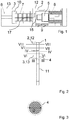
- Fig. 1 shows a partial cross-sectional view of a vacuum cleaner according to the invention.
- the vacuum cleaner has a separation unit which has a separation container 3 and a drive unit container 2 which are permanently connected.
- the separating container 3 is designed to collect suction material, while the adjacent drive unit container 2 contains a drive unit 5 which is designed to generate a suction flow.
- the separation container 3 has a first filter stage 6 and a second filter stage 7, while the drive unit container 2 has a third filter stage 8.
- the first filter stage 6 has a cyclone generated during operation, while the second filter stage 7 has a prefilter and the third filter stage 8 has a central filter.
- the first filter stage 6, the second filter stage 7 and the third filter stage 8 are arranged one behind the other in terms of flow in the specified order.
- the pre-filter and the central filter are arranged axially.
- the first filter stage 6 has an inner wall 10 and a dip tube 17.
- the drive unit container 2 has a drive unit container outer housing 12 into which a fourth filter stage 9 in the form of an exhaust air filter is optionally integrated. Furthermore, the drive unit container 2 has a drive unit housing 15 in which the drive unit 5 is installed.
- the drive unit 5 During operation, the drive unit 5 generates a suction flow, which is partially indicated by the arrows.
- the suction flow passes through the first filter stage 6, where it hits the inner wall 10 and a cyclone forms.
- the suction flow then passes through the second filter stage 7, then flows around the drive unit housing 15 and is directed to the third filter stage 8, where it flows circumferentially.
- the suction flow arrives in a space defined by the drive unit housing 15 in which the drive unit 5 is located and can exit from this space through the filter stage 9 and thus leave the vacuum cleaner.
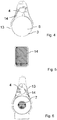
- FIG. 11 shows a perspective view of the FIG Fig. 1 shown vacuum cleaner.
- the vacuum cleaner has a handle 1 which is connected to the drive unit container 2 is. Furthermore, the vacuum cleaner has a suction tube 4, which can also optionally be connected to an extension tube 11 or a floor nozzle (not shown).
- the suction flow first flows through the extension pipe 11, passes the suction pipe 4, then flows out of the suction pipe 4 into the separator container 3 and then from this into the drive unit container 2 and then leaves the vacuum cleaner.
- FIG. 11 shows a cross-sectional view of the in FIG Fig. 2 shown vacuum cleaner along the line III-III.
- the suction pipe 4 is arranged in front of the first filter stage (not shown) and has a circular cross section with a suction pipe diameter D.
- FIG. 11 shows another cross-sectional view of the FIG Fig. 2 shown vacuum cleaner along the line IV-IV.
- the suction pipe 4 is connected to the separating container 3 via an inlet slot 14, which runs tangentially into this and the first filter stage 6.
- the suction flow from the suction pipe 4 is directed tangentially to the inner wall (not shown) of the separating container 3, so that a cyclone (not shown) is formed in the first filter stage 6.
- FIG. 11 shows another partial cross-sectional view of the FIG Fig. 2 shown vacuum cleaner along the line IV-IV.
- the inlet slot 14 has a rectangular cross section with a width b and a height h.
- the rectangular cross-section has an area approximately equal to the area of the in Fig. 3 the suction pipe diameter shown.
- FIG. 11 shows another cross-sectional view of the FIG Fig. 2 shown vacuum cleaner along the line VI-VI.
- the filter stage diameter d has an area approximately equal to the area of the in Fig. 3 the suction pipe diameter shown.
- FIG. 11 shows another cross-sectional view of the FIG Fig. 2 shown vacuum cleaner along the line VII-VII.
- the drive unit 5 is arranged in the drive unit housing 15 upstream of the third filter stage (not shown).
- An area of the cross section between the drive unit housing 15 and the drive unit container outer housing 12 is approximately equal to the area of the in FIG Fig. 3 shown suction pipe diameter.
- the drive unit container 2 is connected to the handle 1. During operation, the suction stream flows between the drive unit housing 15 and the drive unit container outer housing 12 in a circular segment-shaped flow cross-section which is interrupted by functional geometries (not shown).
- FIG. 11 shows another cross-sectional view of the FIG Fig. 2 shown vacuum cleaner along the line VIII-VIII.
- the third filter stage 8 is arranged in the drive unit container 2 and surrounded by the drive unit outer housing 12. It is as the central filter educated.
- the drive unit housing 15 has an opening 16. During operation, the suction flow flows through the central filter and then through the opening 16 into the drive unit housing 15.
- FIG. 11 shows another partial cross-sectional view of the FIG Fig. 2 shown vacuum cleaner.
- the second filter stage 7 can be removed from the separating container 3 in the direction of the arrow, while the third filter stage 8 can be removed from the drive unit container 2 in the direction of the arrow.
- the second filter stage 7 and the third filter stage 8 can therefore be removed in opposite directions.
Landscapes
- Engineering & Computer Science (AREA)
- Mechanical Engineering (AREA)
- Filters For Electric Vacuum Cleaners (AREA)
Abstract
Description
- Die Erfindung betrifft einen handgeführten Zyklon-Staubsauger, der nachfolgend der Einfachheit halber als Staubsauger bezeichnet wird. Insbesondere betrifft die Erfindung einen Staubsauger, der einen Abscheidebehälter zur Aufnahme von Sauggut und einen Antriebsaggregatbehälter aufweist, der ein Antriebsaggregat aufweist, das ausgebildet ist, bei Betrieb einen Saugluftstrom zu erzeugen.
- Ein derartiger Staubsauger ist aus der
WO2017/046 559 A1 bekannt. Der Staubsauger weist zwei Filterstufen auf, die über eine Zyklontechnologie realisiert sind, so dass sie als Multizyklon ausgebildet sind. Weiterhin weist der Staubsauger eine dem Multizyklon strömungstechnisch nachgeschaltete dritte Filterstufe auf, die um ein eingekapseltes Radialgebläse herum gebaut ist. Eine axiale Ausströmung des Gebläses wird durch einen Abluftfilter geleitet. Die Anströmung der verschiedenen Filterstufen benötigt jedoch einen relativ großen Bauraum. - Der Erfindung stellt sich somit das Problem, einen handgeführten Zyklon-Staubsauger bereitzustellen, der mehrere Filterstufen aufweist, die in einem kompakten Bauraum realisiert sind. Zudem sollten die Filterstufen für den Nutzer zugänglich sein.
- Erfindungsgemäß wird dieses Problem durch einen handgeführten Zyklon-Staubsauger mit den Merkmalen des Patentanspruchs 1 gelöst. Vorteilhafte Ausgestaltungen und Weiterbildungen der Erfindung ergeben sich aus den nachfolgenden Unteransprüchen.
- Durch die Erfindung wird ein Staubsauger in einer kompakten Bauform zur Verfügung gestellt, welcher mehrere Filterstufen aufweist. Die Realisierung mehrerer Filterstufen ermöglicht eine besonders effektive Abscheideeinheit mit einer besonders trennscharfen ersten Filterstufe. Gleichzeitig sind alle Filterstufen der Abscheideeinheit, welche einer periodischen Reinigung bedürfen, für den Benutzer einfach zugänglich angeordnet.
- Die Erfindung betrifft einen handgeführten Zyklon-Staubsauger, aufweisend eine Abscheideeinheit zum Sammeln von Sauggut, die ein Antriebsaggregat zum Erzeugen eines Saugstroms, eine erste Filterstufe, eine zweite Filterstufe und eine dritte Filterstufe aufweist; wobei das Antriebsaggregat saugstromabwärts der zweiten Filterstufe und saugstromaufwärts der dritten Filterstufe in einem Antriebsaggregatgehäuse angeordnet ist, wobei das Antriebsaggregat von dem bei Betrieb des Antriebsaggregates erzeugten Saugstrom umströmt wird. Das Antriebsaggregat ist dabei räumlich zwischen der der zweiten Filterstufe und der dritten Filterstufe in einem Antriebsaggregatgehäuse angeordnet.
- Dadurch, dass das sich in dem Antriebsaggregatgehäuse befindende Antriebsaggregat von dem Saugstrom umströmbar ist, wird Bauraum eingespart.
- Unter dem Ausdruck "handgeführt" ist zu verstehen, dass der Staubsauger per Hand von dem Nutzer bei Betrieb geführt wird. Dazu weist der Staubsauger bevorzugt weiterhin einen Handgriff auf. Bevorzugt ist der Handgriff mit der Abscheideeinheit fest verbunden oder verbindbar.
- Unter dem Begriff "Zyklon-Staubsauger" ist ein Staubsauger zu verstehen, der beutellos ist und bei dem der Saugstrom in der Abscheideeinheit einen Wirbelstrom ausbildet, welcher zur Abtrennung von Staub- und Schmutzpartikeln aus dem Saugstrom unter Gravitationseinfluss fungiert. Die erste Filterstufe der Abscheideeinheit des Zyklon-Staubsaugers bildet eine Längsachse aus, wobei im Betrieb des Antriebsaggregats der Saugstrom einen Wirbelstrom um die Längsachse der ersten Filterstufe ausbildet, wobei die Längsachse der ersten Filterstufe parallel zur Längsachse des Saugrohres ausgerichtet ist. Die parallele Ausrichtung der Längsachsen der ersten Filterstufe und des Saugrohrs sind maßgeblich für die Realisierung eines Staubsaugers mit einer kompakten Bauform.
- Unter dem Ausdruck "beutellos" ist zu verstehen, dass das Sauggut in dem Staubsauger direkt in der Abscheideeinheit gesammelt wird, ohne dass in dieser ein Beutel oder ein ähnliches Wechselfiltermedium zur Aufnahme von Sauggut angeordnet ist, so dass der Nutzer zur Entleerung des Saugguts aus der Abscheideeinheit keinen Beutel oder dgl. aus dem Abscheidebehälter entnimmt. Der Staubsauger weist aber mehrere Filtermedien auf, die verhindern, dass aufgesaugtes Sauggut in das in dem Antriebsaggregatgehäuse angeordnete Antriebsaggregat gelangt.
- In einer bevorzugten Ausführungsform ist das Antriebsaggregat derart angeordnet, dass eine Einströmrichtung des Saugstroms in das Antriebsaggregat entgegengesetzt ist zu einer Strömungsrichtung des Saugstroms von der zweiten Filterstufe zu der dritten Filterstufe. Der erzeugte Saugstrom ändert seine Richtung daher auch um 180° während seines Weges innerhalb des Staubsaugers. Das Antriebsaggregat, das bevorzugt als Gebläse ausgebildet ist, ist bevorzugt um 180° gedreht in Bezug auf ein Saugrohr des Staubsaugers, in das der Saugstrom in den Staubsauger vor Eintritt in die drei Filterstufen eintritt. D. h., eine Strömungsrichtung des in das Saugrohr einströmenden Saugstroms ist entgegengesetzt zu einer weiteren Strömungsrichtung des in das Antriebsaggregat eintretenden Saugstroms.
- Bevorzugt weist die erste Filterstufe einen bei Betrieb vom Antriebsaggregat erzeugten Zyklon, die zweite Filterstufe einen Vorfilter und die dritte Filterstufe einen Zentralfilter auf. Bevorzugt weist der Zentralfilter ein Speichermedium auf, das ausgebildet ist, Staub zu speichern. Er ist bevorzugt als Feinfilter ausgelegt. Der Vorfilter dient im Wesentlichen als Filterschutz für den Zentralfilter und ist im Wesentlichen ausgelegt, Grobpartikel an einem Eintreten in einen Raum zwischen der zweiten Filterstufe und der dritten Filterstufe zu hindern.
- Bevorzugt sind der Vorfilter und der Zentralfilter axial entlang der Längsachse der Abscheideeinheit angeordnet. Bevorzugt erstreckt sich die Abscheideeinheit entlang einer Längsachse. Bevorzugt erstrecken sich der Vorfilter und der Zentralfilter jeweils parallel zu der Längsachse.
- Bevorzugt sind die erste Filterstufe, die zweite Filterstufe und die dritte Filterstufe in der angegebenen Reihenfolge strömungstechnisch hintereinander angeordnet. Das bedeutet, dass der erzeugte Saugstrom zunächst die erste Filterstufe, dann die zweite Filterstufe und schließlich die dritte Filterstufe passiert.
- In einer bevorzugten Ausführungsform weist die erste Filterstufe weiterhin einen Einlaufschlitz auf, der derart angeordnet ist, dass bei Betrieb der Saugstrom aus dem Einlaufschlitz an eine Innenwand des Abscheidebehälters tangential geleitet wird, so dass sich ein Zyklon in der ersten Filterstufe bei Betrieb ausbildet. Der Zyklonwirbel bildet sich bei Betrieb in der ersten Filterstufe aus, so dass sich Partikel mit einem gewissen Druckverlust und einem gewissen Trennkorn abscheiden. Die erste Filterstufe weist bevorzugt den Einlaufschlitz, die Innenwand und ein Tauchrohr auf. Das Tauchrohr ist bevorzugt mit der Innenwand fest verbunden und auf einer Seite der Innenwand angeordnet, die von der zweiten Filterstufe abgewandt ist. Der Einlaufschlitz weist bevorzugt einen rechteckigen Querschnitt auf.
- Bevorzugt weist der Staubsauger das Saugrohr auf, aus dem bei Betrieb der Saugstrom in den Einlaufschlitz strömt. Das Saugrohr weist bevorzugt einen kreisförmigen Querschnitt auf. Das Saugrohr ist bevorzugt mit einer Bodendüse und/oder einem Verlängerungsrohr verbindbar. Das Saugrohr weist eine Längsachse auf, welche im Mittelpunkt seines kreisförmigen Querschnittsliegt und sich entlang der gesamten Länge des Saugrohrs erstreckt.
- Bevorzugt weist die zweite Filterstufe einen Vorfilter auf. Der Vorfilter ist bevorzugt aus einer Gewebegaze, einem Kunststoffsieb, einem Stanzgitter oder einer Metallgaze ausgebildet. Bevorzugt weist die zweite Filterstufe weiterhin ein Innenrohr auf, das mit dem Vorfilter verbunden ist. Bevorzugt ist das Innenrohr strömungstechnisch hinter dem Vorfilter und vor der dritten Filterstufe angeordnet. Bevorzugt ist der Vorfilter zwischen der Innenwand und dem Innenrohr angeordnet.
- In einer bevorzugten Ausführungsform ist der Zentralfilter ein zylinderförmiger Filter, der zum Antriebsaggregat und zu einem Abscheideeinheit-Außengehäuse abgedichtet ist. Bevorzugt weist der Zentralfilter ein Speichermedium auf, das ausgebildet ist, Staub zu speichern. Er ist bevorzugt als Feinfilter ausgelegt. Der Vorfilter dient im Wesentlichen als Filterschutz für den Zentralfilter und ist im Wesentlichen ausgelegt, Grobpartikel an einem Eintreten in einen Raum zwischen der zweiten Filterstufe und der dritten Filterstufe zu hindern.
- Bevorzugt ist die dritte Filterstufe derart angeordnet, dass der bei Betrieb erzeugte Saugstrom axial in das Antriebsaggregat einströmt. Dies ermöglicht eine kompakte Bauform des Staubsaugers.
- In einer bevorzugten Ausführungsform ist die zweite Filterstufe aus der Abscheideeinheit in eine Entnahmerichtung entnehmbar, die entgegengesetzt ist zu einer weiteren Entnahmerichtung, in die die dritte Filterstufe aus der Abscheideeinheit entnehmbar ist. Durch die parallel verschobene Anordnung der zweiten Filterstufe und der dritten Filterstufe sind beide unabhängig voneinander entnehmbar. Bevorzugt ist der Vorfilter mit der Innenwand der ersten Filterstufe lösbar verbunden, die mit dem Tauchrohr verbunden ist, so dass die zweite Filterstufe mittels Entnahme des Tauchrohrs aus dem Abscheidebehälter entnehmbar ist.
- In einer bevorzugten Ausführungsform weist der Staubsauger weiterhin eine vierte Filterstufe, die strömungstechnisch hinter der dritten Filterstufe angeordnet ist und die ein Abluftfilterelement aufweist. Das Abluftfilterelement ist bevorzugt als ein Filter oder eine Klappe in einem Außengehäuse der Abscheideeinheit ausgebildet.
- In einer bevorzugten Ausführungsform weist die Abscheideeinheit einen Antriebsaggregatbehälter und einen Abscheidebehälter auf, wobei der Antriebsaggregatbehälter das Antriebsaggregatgehäuse, das Antriebsaggregat und die dritte Filterstufe enthält und der Abscheidebehälter die erste und die zweite Filterstufe aufweist. Bevorzugt sind der Antriebsaggregatbehälter und der Abscheidebehälter benachbart angeordnet und erstrecken sich entlang parallelen Längsachsen. Bevorzugt sind der Abscheidebehälter und der Antriebsaggregatbehälter unlösbar miteinander verbunden.
- Bevorzugt ist das Antriebsaggregatgehäuse von einem kreissegmentförmigen Strömungsquerschnitt umgeben, durch den der Saugstrom bei Betrieb strömt, bevor er die dritte Filterstufe erreicht. Dadurch wird der Staubsauger weiterhin kompakt bereitgestellt. Der kreissegmentförmige Strömungsquerschnitt kann jedoch partiell von Funktionsgeometrie(n) unterbrochen sein. Bevorzugt sind das Antriebsaggregatgehäuse, der Strömungsquerschnitt und der Zentralfilter derart ausgebildet und angeordnet, dass die dritte Filterstufe umfänglich von dem Saugstrom bei Betrieb angeströmt wird.
- Bevorzugt ein Saugrohr-Durchmesser des Saugrohrs im Wesentlichen gleich zu einer Querschnittsfläche des Einlaufschlitzes mit einem rechteckigen Querschnitt. Bevorzugt ist der Saugrohr-Durchmesser im Wesentlichen gleich zu einem Filterstufen-Durchmesser des Innenrohrs der zweiten Filterstufe und/oder gleich zu einem Durchmesser des Vorfilters. Eine Fläche des Strömungsquerschnitts zwischen dem Antriebsaggregatgehäuse und dem Antriebsaggregatbehälter-Außengehäuse ist bevorzugt etwa gleich zu der Fläche des Saugrohr-Durchmessers Mit den Durchmessern sind insbesondere Innendurchmesser gemeint.
- Bevorzugt liegt der Durchmesser des Saugrohrs im Bereich von 20 bis 40 mm, bevorzugt 25 bis 35 mm. Bevorzugt weist die erste Filterstufe folgende Abmessungen auf: Bevorzugter weist der Zyklon einen Durchmesser im Bereich von 90 bis 100 mm auf, eine Höhe des Zyklons, die als eine Abmessung zwischen dem Einlaufschlitz und der Innenwand definiert ist, liegt bevorzugt im Bereich von 80 bis 140 mm, bevorzugt 110 bis 130 mm. Eine Höhe des Tauchrohrs, die eine Längserstreckung des Tauchrohr ausgehend von der Innenwand darstellt, liegt bevorzugt im Bereich von 20 - 60 mm, bevorzugter 30 bis 50 mm, und ein Durchmesser des Tauchrohrs beträgt bevorzugt 35 - 60 mm, bevorzugter 40 bis 50 mm. Eine Breite des Einlaufschlitzes ist bevorzugt 14 - 30 mm, bevorzugt 18 bis 26, während eine Höhe des Einlaufschlitzes bevorzugt 20 - 52 mm, bevorzugt 30 bis 40 mm beträgt, wobei die Höhe und Breite des Einlaufschlitzes einen Querschnitt des Einlaufschlitzes definieren. Je kleiner der Durchmesser des Vorfilters ist, desto besser ist eine Trennung zwischen der zweiten und der dritten Filterstufe und desto besser ist ihre Abscheideleistung.
- Bevorzugt ist der Antriebsaggregatbehälter mit dem Handgriff verbunden. In einer betriebsgemäßen Arbeitsposition befindet sich der Antriebsaggregatbehälter bevorzugt an einer Rückseite bzw. hinterem Ende des Staubsaugers, womit gemeint ist, dass er ist näher an der Hand des Nutzers und weiter von dem zu saugenden Untergrund entfernt ist als der Abscheidebehälter.
- Der Staubsauger ist bevorzugt ein Akkustaubsauger. D.h., der Staubsauger weist einen Akkumulator auf und ist ausgelegt, mittels des Akkumulators als Stromquelle betrieben zu werden. Der Akkumulator ist mit dem Sauggutbehälter und/oder dem Gerätekorpus bevorzugt dem Gerätekorpus verbindbar.
- Weiterhin kann der Staubsauger ein Verlängerungsrohr aufweisen, das mit dem Saugrohr verbindbar ist. Ferner kann der Staubsauger eine Bodendüse aufweisen, die mit dem Saugrohr und dem Verlängerungsrohr verbindbar ist.
- Das Antriebsaggregat ist bevorzugt als ein Gebläse ausgebildet.
- Ein Ausführungsbeispiel der Erfindung ist in den Zeichnungen rein schematisch dargestellt und wird nachfolgend näher beschrieben. Es zeigt
- Fig. 1
- eine Teil-Querschnittsansicht eines erfindungsgemäßen Staubsaugers;
- Fig. 2
- eine perspektivische Ansicht des in
Fig. 1 gezeigten Staubsaugers; - Fig. 3
- eine Querschnittsansicht des in
Fig. 2 gezeigten Staubsaugers; - Fig.4
- eine weitere Querschnittsansicht des in
Fig. 2 gezeigten Staubsaugers; - Fig. 5
- eine weitere Teil-Querschnittsansicht des in
Fig. 2 gezeigten Staubsaugers; - Fig. 6
- eine weitere Querschnittsansicht des in
Fig. 2 gezeigten Staubsaugers; - Fig. 7
- eine weitere Querschnittsansicht des in
Fig. 2 gezeigten Staubsaugers; - Fig. 8
- eine weitere Querschnittsansicht des in
Fig. 2 gezeigten Staubsaugers; und - Fig. 9
- eine weitere Teil-Querschnittsansicht des in
Fig. 2 gezeigten Staubsaugers. -
Fig. 1 zeigt eine Teil-Querschnittsansicht eines erfindungsgemäßen Staubsaugers. Der Staubsauger weist eine Abscheideeinheit auf, die einen Abscheidebehälter 3 und einen Antriebsaggregatbehälter 2 aufweist, die unlösbar verbunden sind. Der Abscheidebehälter 3 ist zum Sammeln von Sauggut ausgebildet, während der benachbarte Antriebsaggregatbehälter 2 ein Antriebsaggregat 5 enthält, das zum Erzeugen eines Saugstroms ausgebildet ist. Der Abscheidebehälter 3 weist eine erste Filterstufe 6 und eine zweite Filterstufe 7 auf, während der Antriebsaggregatbehälter 2 eine dritte Filterstufe 8 aufweist. Die erste Filterstufe 6 weist einen bei Betrieb erzeugten Zyklon auf, während die zweite Filterstufe 7 einen Vorfilter aufweist und die dritte Filterstufe 8 einen Zentralfilter aufweist. - Die erste Filterstufe 6, die zweite Filterstufe 7 und die dritte Filterstufe 8 sind in der angegebenen Reihenfolge strömungstechnisch hintereinander angeordnet. Der Vorfilter und der Zentralfilter sind axial angeordnet. Die erste Filterstufe 6 weist eine Innenwand 10 und ein Tauchrohr 17 auf. Der Antriebsaggregatbehälter 2 weist ein Antriebsaggregatbehälter-Außengehäuse 12 auf, in das optional eine vierte Filterstufe 9 in Form eines Abluftfilters integriert ist. Weiterhin weist der Antriebsaggregatbehälter 2 ein Antriebsaggregatgehäuse 15 auf, in das das Antriebsaggregat 5 eingebaut ist.
- Bei Betrieb erzeugt das Antriebsaggregat 5 einen Saugstrom, der teilweise durch die Pfeile angedeutet ist. Zuerst passiert der Saugstrom die erste Filterstufe 6, wobei er auf die Innenwand 10 prallt und sich ein Zyklon ausbildet. Dann passiert der Saugstrom die zweite Filterstufe 7, umströmt dann das Antriebsaggregatgehäuse 15 und wird zur dritten Filterstufe 8 geleitet und strömt diese umfänglich an. Nach Passieren der dritten Filterstufe 8 gelangt der Saugstrom in einen von dem Antriebsaggregatgehäuse 15 definierten Raum, in dem sich das Antriebsaggregat 5 befindet und kann aus diesem Raum durch die Filterstufe 9 austreten und damit den Staubsauger verlassen.
-
Fig. 2 zeigt eine perspektivische Ansicht des inFig. 1 gezeigten Staubsaugers. Der Staubsauger weist einen Handgriff 1 auf, der mit dem Antriebsaggregatbehälter 2 verbunden ist. Weiterhin weist der Staubsauger ein Saugrohr 4 auf, das weiterhin optional mit einem Verlängerungsrohr 11 oder einer Bodendüse (nicht gezeigt) verbindbar ist. - Bei Betrieb strömt der Saugstrom zuerst durch das Verlängerungsrohr 11, passiert das Saugrohr 4, strömt dann aus dem Saugrohr 4 in den Abscheidebehälter 3 und dann aus diesem in den Antriebsaggregatbehälter 2 und verlässt anschließend den Staubsauger.
-
Fig. 3 zeigt eine Querschnittsansicht des inFig. 2 gezeigten Staubsaugers entlang der Linie III-III. Das Saugrohr 4 ist vor der ersten Filterstufe (nicht gezeigt) angeordnet und weist einen kreisrunden Querschnitt mit einem Saugrohr-Durchmesser D auf. -
Fig.4 zeigt eine weitere Querschnittsansicht des inFig. 2 gezeigten Staubsaugers entlang der Linie IV-IV. Das Saugrohr 4 ist über einen Einlaufschlitz 14 mit dem Abscheidebehälter 3 verbunden, der tangential in diesen und die erste Filterstufe 6 einläuft. Bei Betrieb wird der Saugstrom aus dem Saugrohr 4 an die Innenwand (nicht gezeigt) des Abscheidebehälters 3 tangential geleitet, so dass sich ein Zyklon (nicht gezeigt) in der ersten Filterstufe 6 ausbildet. -
Fig. 5 zeigt eine weitere Teil-Querschnittsansicht des inFig. 2 gezeigten Staubsaugers entlang der Linie IV-IV. Der Einlaufschlitz 14 weist einen rechteckigen Querschnitt mit einer Breite b und einer Höhe h auf. Der rechteckige Querschnitt weist eine Fläche auf, die etwa gleich zu der Fläche des inFig. 3 gezeigten Saugrohr-Durchmessers ist. -
Fig. 6 zeigt eine weitere Querschnittsansicht des inFig. 2 gezeigten Staubsaugers entlang der Linie VI-VI. Der Vorfilter oder ein strömungstechnisch nach dem Vorfilter liegendes Innenrohr (nicht gezeigt) der zweiten Filterstufe 7 weist einen kreisförmigen Querschnitt mit einem Filterstufen-Durchmesser d auf. Der Filterstufen-Durchmesser d weist eine Fläche auf, die etwa gleich zu der Fläche des inFig. 3 gezeigten Saugrohr-Durchmessers ist. -
Fig. 7 zeigt eine weitere Querschnittsansicht des inFig. 2 gezeigten Staubsaugers entlang der Linie VII-VII. Vor der dritten Filterstufe (nicht gezeigt) ist das Antriebsaggregat 5 in dem Antriebsaggregatgehäuse 15 angeordnet. Eine Fläche des Querschnitts zwischen dem Antriebsaggregatgehäuse 15 und dem Antriebsaggregatbehälter-Außengehäuse 12 ist etwa gleich zu der Fläche des inFig. 3 gezeigten Saugrohr-Durchmessers. Der Antriebsaggregatbehälter 2 ist mit dem Handgriff 1 verbunden. Bei Betrieb strömt der Saugstrom zwischen dem Antriebsaggregatgehäuse 15 und dem Antriebsaggregatbehälter-Außengehäuse 12 in einem kreissegmentförmigen Strömungsquerschnitt, der durch Funktionsgeometrien (nicht gezeigt) unterbrochen ist. -
Fig. 8 zeigt eine weitere Querschnittsansicht des inFig. 2 gezeigten Staubsaugers entlang der Linie VIII-VIII. Die dritte Filterstufe 8 ist im Antriebsaggregatbehälter 2 angeordnet und von dem Antriebsaggregat-Außengehäuse 12 umgeben. Sie ist als der Zentralfilter ausgebildet. Das Antriebsaggregatgehäuse 15 weist eine Öffnung 16 auf. Bei Betrieb strömt der Saugstrom durch den Zentralfilter und anschließend durch die Öffnung 16 in das Antriebsaggregatgehäuse 15. -
Fig. 9 zeigt eine weitere Teil-Querschnittsansicht des inFig. 2 gezeigten Staubsaugers. Die zweite Filterstufe 7 ist in Richtung des Pfeils aus dem Abscheidebehälter 3 entnehmbar, während die dritte Filterstufe 8 in Richtung des Pfeils aus dem Antriebsaggregatbehälter 2 entnehmbar ist. Die zweite Filterstufe 7 und die dritte Filterstufe 8 sind daher in entgegengesetzt Richtungen entnehmbar. -
- b
- Breite
- d
- Filterstufen-Durchmesser
- D
- Saugrohr-Durchmesser
- h
- Höhe
- 1
- Handgriff
- 2
- Antriebsaggregatbehälter
- 3
- Abscheidebehälter
- 4
- Saugrohr
- 5
- Antriebsaggregat
- 6
- erste Filterstufe
- 7
- zweite Filterstufe
- 8
- dritte Filterstufe
- 9
- vierte Filterstufe
- 10
- Innenwand
- 11
- Verlängerungsrohr
- 12
- Antriebsaggregatbehälter-Außengehäuse
- 13
- Abscheidebehälter-Außengehäuse
- 14
- Einlaufschlitz
- 15
- Antriebsaggregatgehäuse
- 16
- Öffnung
- 17
- Tauchrohr
Claims (10)
- Handgeführter Zyklon-Staubsauger, aufweisend eine Abscheideeinheit zum Sammeln von Sauggut, die ein Antriebsaggregat (5) zum Erzeugen eines Saugstroms, eine erste Filterstufe (6), eine zweite Filterstufe (7) und eine dritte Filterstufe (8) aufweist; wobei das Antriebsaggregat (5) saugstromabwärts der zweiten Filterstufe (7) und saugstromaufwärts der dritten Filterstufe (8) in einem Antriebsaggregatgehäuse (15) angeordnet ist, wobei das Antriebsaggregat (5) von dem bei Betrieb des Antriebsaggregates (5) erzeugten Saugstrom umströmt wird.
- Staubsauger nach Anspruch 1, dadurch gekennzeichnet, dass das Antriebsaggregat (5) derart im Antriebsaggregatsgehäuse (15) angeordnet ist, dass eine Einströmrichtung des Saugstroms in das Antriebsaggregat (5) entgegengesetzt ist zu einer Strömungsrichtung des Saugstroms von der zweiten Filterstufe (2) zu der dritten Filterstufe (8).
- Staubsauger nach Anspruch 1 oder 2, dadurch gekennzeichnet, dass die erste Filterstufe (6) einen bei Betrieb vom Antriebsaggregat (5) erzeugten Zyklon, die zweite Filterstufe (7) einen Vorfilter und die dritte Filterstufe (8) einen Zentralfilter aufweist und wobei der Vorfilter und der Zentralfilter axial angeordnet sind, wobei die erste Filterstufe (6), die zweite Filterstufe (7) und die dritte Filterstufe (8) in der angegebenen Reihenfolge strömungstechnisch hintereinander angeordnet sind.
- Staubsauger nach einem der vorangehenden Ansprüche, dadurch gekennzeichnet, dass die dritte Filterstufe (8) derart angeordnet ist, dass der bei Betrieb erzeugte Saugstrom axial in das Antriebsaggregat (5) einströmt.
- Staubsauger nach einem der vorangehenden Ansprüche, dadurch gekennzeichnet, dass die zweite Filterstufe (7) aus der Abscheideeinheit in eine Entnahmerichtung entnehmbar ist, die entgegengesetzt ist zu einer weiteren Entnahmerichtung, in die die dritte Filterstufe (8) aus der Abscheideeinheit entnehmbar ist.
- Staubsauger nach einem der vorangehenden Ansprüche, gekennzeichnet durch eine vierte Filterstufe (9), die strömungstechnisch hinter der dritten Filterstufe (8) angeordnet ist und die ein Abluftfilterelement aufweist, das bevorzugt als ein Filter oder eine Klappe in einem Außengehäuse der Abscheideeinheit ausgebildet ist.
- Staubsauger nach einem der vorangehenden Ansprüche, dadurch gekennzeichnet, dass die zweite Filterstufe (7) einen Vorfilter aus einer Gewebegaze, einem Kunststoffsieb, einem Stanzgitter oder einer Metallgaze aufweist.
- Staubsauger nach einem der vorangehenden Ansprüche, dadurch gekennzeichnet, dass die dritte Filterstufe (8) einen zylinderförmigen Zentralfilter aufweist, der zum Antriebsaggregat (5) und zu einem Außengehäuse (12) der Abscheideeinheit abgedichtet ist.
- Staubsauger nach einem der vorangehenden Ansprüche, dadurch gekennzeichnet, dass die Abscheideeinheit einen Antriebsaggregatbehälter (2) und einen Abscheidebehälter (3) aufweist, wobei der Antriebsaggregatbehälter (2), das Antriebsaggregatgehäuse (15), das Antriebsaggregat (5) und die dritte Filterstufe (8) enthält und der Abscheidebehälter (3) die erste und die zweite Filterstufe (6, 7) aufweist und wobei der Antriebsaggregatbehälter (3) und der Abscheidebehälter (3) benachbart angeordnet sind und sich jeweils entlang parallelen Längsachsen erstrecken.
- Staubsauger nach einem der vorangehenden Ansprüche, dadurch gekennzeichnet, dass das Antriebsaggregatgehäuse (15) von einem kreissegmentförmigen Strömungsquerschnitt umgeben ist, durch den der Saugstrom bei Betrieb strömt, bevor er die dritte Filterstufe (8) erreicht.
Priority Applications (1)
| Application Number | Priority Date | Filing Date | Title |
|---|---|---|---|
| EP22207103.7A EP4169427B1 (de) | 2020-05-05 | 2021-04-20 | Handgeführter zyklon-staubsauger |
Applications Claiming Priority (1)
| Application Number | Priority Date | Filing Date | Title |
|---|---|---|---|
| DE102020112086.9A DE102020112086A1 (de) | 2020-05-05 | 2020-05-05 | Handgeführter Zyklon-Staubsauger |
Related Child Applications (2)
| Application Number | Title | Priority Date | Filing Date |
|---|---|---|---|
| EP22207103.7A Division-Into EP4169427B1 (de) | 2020-05-05 | 2021-04-20 | Handgeführter zyklon-staubsauger |
| EP22207103.7A Division EP4169427B1 (de) | 2020-05-05 | 2021-04-20 | Handgeführter zyklon-staubsauger |
Publications (2)
| Publication Number | Publication Date |
|---|---|
| EP3906830A1 true EP3906830A1 (de) | 2021-11-10 |
| EP3906830B1 EP3906830B1 (de) | 2024-06-26 |
Family
ID=75588093
Family Applications (2)
| Application Number | Title | Priority Date | Filing Date |
|---|---|---|---|
| EP22207103.7A Active EP4169427B1 (de) | 2020-05-05 | 2021-04-20 | Handgeführter zyklon-staubsauger |
| EP21169274.4A Active EP3906830B1 (de) | 2020-05-05 | 2021-04-20 | Handgeführter zyklon-staubsauger |
Family Applications Before (1)
| Application Number | Title | Priority Date | Filing Date |
|---|---|---|---|
| EP22207103.7A Active EP4169427B1 (de) | 2020-05-05 | 2021-04-20 | Handgeführter zyklon-staubsauger |
Country Status (3)
| Country | Link |
|---|---|
| EP (2) | EP4169427B1 (de) |
| CN (1) | CN113598647A (de) |
| DE (1) | DE102020112086A1 (de) |
Citations (8)
| Publication number | Priority date | Publication date | Assignee | Title |
|---|---|---|---|---|
| WO2017046559A1 (en) | 2015-09-17 | 2017-03-23 | Dyson Technology Limited | Vacuum cleaner |
| US20170290479A1 (en) * | 2016-04-11 | 2017-10-12 | Omachron Intellectual Property Inc. | Surface cleaning apparatus |
| EP3287059A1 (de) * | 2016-06-30 | 2018-02-28 | Jiangsu Midea Cleaning Appliances Co., Ltd. | Staubfanganordnung und tragbarer staubsauger damit |
| US20190008340A1 (en) * | 2017-07-06 | 2019-01-10 | Omachron Intellectual Property Inc. | Handheld surface cleaning apparatus |
| US20190307304A9 (en) * | 2013-02-28 | 2019-10-10 | Omachron Intellectual Property Inc. | Hand carryable surface cleaning apparatus |
| EP3563739A1 (de) * | 2017-01-03 | 2019-11-06 | Samsung Electronics Co., Ltd. | Stabstaubsauger |
| WO2019231153A1 (en) * | 2018-05-31 | 2019-12-05 | Lg Electronics Inc. | Cleaner |
| WO2019231157A1 (en) * | 2018-05-31 | 2019-12-05 | Lg Electronics Inc. | Cleaning appliance |
Family Cites Families (9)
| Publication number | Priority date | Publication date | Assignee | Title |
|---|---|---|---|---|
| US9320401B2 (en) * | 2013-02-27 | 2016-04-26 | Omachron Intellectual Property Inc. | Surface cleaning apparatus |
| KR102560970B1 (ko) * | 2016-03-31 | 2023-07-31 | 엘지전자 주식회사 | 청소기 |
| EP4413908A3 (de) * | 2016-03-31 | 2024-11-27 | LG Electronics Inc. | Reinigungsgerät |
| CN206576819U (zh) * | 2016-11-22 | 2017-10-24 | 科沃斯机器人股份有限公司 | 手持式吸尘器 |
| CN106618374B (zh) * | 2017-02-24 | 2022-04-08 | 江苏美的清洁电器股份有限公司 | 手持吸尘器 |
| GB2578250B (en) * | 2017-07-06 | 2020-11-04 | Omachron Intellectual Property Inc | Handheld surface cleaning apparatus |
| CN107343774A (zh) * | 2017-09-12 | 2017-11-14 | 苏州诚河清洁设备有限公司 | 手持式吸尘器 |
| CN209377457U (zh) * | 2018-07-11 | 2019-09-13 | 尚科宁家(香港)股份有限公司 | 一种手持式清洁装置 |
| CN109330476A (zh) * | 2018-11-27 | 2019-02-15 | 江苏美的清洁电器股份有限公司 | 手持清洁设备 |
-
2020
- 2020-05-05 DE DE102020112086.9A patent/DE102020112086A1/de not_active Withdrawn
-
2021
- 2021-04-20 EP EP22207103.7A patent/EP4169427B1/de active Active
- 2021-04-20 EP EP21169274.4A patent/EP3906830B1/de active Active
- 2021-05-06 CN CN202110490710.7A patent/CN113598647A/zh active Pending
Patent Citations (8)
| Publication number | Priority date | Publication date | Assignee | Title |
|---|---|---|---|---|
| US20190307304A9 (en) * | 2013-02-28 | 2019-10-10 | Omachron Intellectual Property Inc. | Hand carryable surface cleaning apparatus |
| WO2017046559A1 (en) | 2015-09-17 | 2017-03-23 | Dyson Technology Limited | Vacuum cleaner |
| US20170290479A1 (en) * | 2016-04-11 | 2017-10-12 | Omachron Intellectual Property Inc. | Surface cleaning apparatus |
| EP3287059A1 (de) * | 2016-06-30 | 2018-02-28 | Jiangsu Midea Cleaning Appliances Co., Ltd. | Staubfanganordnung und tragbarer staubsauger damit |
| EP3563739A1 (de) * | 2017-01-03 | 2019-11-06 | Samsung Electronics Co., Ltd. | Stabstaubsauger |
| US20190008340A1 (en) * | 2017-07-06 | 2019-01-10 | Omachron Intellectual Property Inc. | Handheld surface cleaning apparatus |
| WO2019231153A1 (en) * | 2018-05-31 | 2019-12-05 | Lg Electronics Inc. | Cleaner |
| WO2019231157A1 (en) * | 2018-05-31 | 2019-12-05 | Lg Electronics Inc. | Cleaning appliance |
Also Published As
| Publication number | Publication date |
|---|---|
| EP3906830B1 (de) | 2024-06-26 |
| EP4169427B1 (de) | 2024-06-26 |
| CN113598647A (zh) | 2021-11-05 |
| EP4169427C0 (de) | 2024-06-26 |
| DE102020112086A1 (de) | 2021-11-11 |
| EP4169427A1 (de) | 2023-04-26 |
Similar Documents
| Publication | Publication Date | Title |
|---|---|---|
| DE102012211245B4 (de) | Staubsauger mit Wirbelabscheider | |
| DE102004028677B4 (de) | Wirbelungs-Abscheidungsvorrichtung und Staubsauger mit einer solchen Abscheidungsvorrichtung | |
| DE102004050911B4 (de) | Staubsammelvorrichtung für einen Staubsauger | |
| DE102005015004B4 (de) | Mehrzyklon-Staubsammelvorrichtung und Staubsauger mit einer solchen | |
| DE102004055897B4 (de) | Wirbelungs-Staubsammelvorrichtung und Staubsauger mit einer solchen Vorrichtung | |
| DE102012211246A1 (de) | Kombination aus einem Kleinsauger und einem Stielsaugerrahmen sowie Kleinsauger und Stielsaugerrahmen | |
| DE10124216A1 (de) | Staubsauger im Hochformat mit einer Staubauffangvorrichtung vom Zyklontyp | |
| DE19827173A1 (de) | Absaugvorrichtung für eine Handwerkzeugmaschine | |
| EP3906829B1 (de) | Handgeführter zyklon-staubsauger | |
| DE102008055045A1 (de) | Staubsauger mit Fliehkraftabscheidern | |
| EP1661662B1 (de) | Grobabscheider für abgesaugte Materialteilchen | |
| EP1731749B1 (de) | Staubaustragssystem | |
| DE102006027456A1 (de) | Staubsammelvorrichtung sowie Staubsauger | |
| DE102004060981B4 (de) | Staubsammelvorrichtung für einen Staubsauger | |
| DE102016100820B4 (de) | Saugreinigungsgerät | |
| DE102011081044A1 (de) | Staubabscheideeinrichtung, insbesondere für Staubsauger | |
| EP3906830B1 (de) | Handgeführter zyklon-staubsauger | |
| EP3773105B1 (de) | Abscheidevorrichtung für staubabsaugvorrichtung | |
| DE202017007339U1 (de) | Abscheidesystem | |
| EP3906831B1 (de) | Handgeführter zyklon-staubsauger | |
| DE102017220700A1 (de) | Fliehkraftabscheider mit verringerter Bauhöhe | |
| BE1028991B1 (de) | Handgeführter Zyklon-Staubsauger | |
| EP3692884B1 (de) | Sauggutbehälter und handgeführter zyklon-staubsauger | |
| DE102011017792A1 (de) | Abscheideeinrichtung mit Flusensieb | |
| DE102017220701A1 (de) | Fliehkraftabscheider mit zentrischer Zuführung der zu reinigenden Luft |
Legal Events
| Date | Code | Title | Description |
|---|---|---|---|
| PUAI | Public reference made under article 153(3) epc to a published international application that has entered the european phase |
Free format text: ORIGINAL CODE: 0009012 |
|
| STAA | Information on the status of an ep patent application or granted ep patent |
Free format text: STATUS: THE APPLICATION HAS BEEN PUBLISHED |
|
| AK | Designated contracting states |
Kind code of ref document: A1 Designated state(s): AL AT BE BG CH CY CZ DE DK EE ES FI FR GB GR HR HU IE IS IT LI LT LU LV MC MK MT NL NO PL PT RO RS SE SI SK SM TR |
|
| B565 | Issuance of search results under rule 164(2) epc |
Effective date: 20211013 |
|
| STAA | Information on the status of an ep patent application or granted ep patent |
Free format text: STATUS: REQUEST FOR EXAMINATION WAS MADE |
|
| 17P | Request for examination filed |
Effective date: 20220510 |
|
| RBV | Designated contracting states (corrected) |
Designated state(s): AL AT BE BG CH CY CZ DE DK EE ES FI FR GB GR HR HU IE IS IT LI LT LU LV MC MK MT NL NO PL PT RO RS SE SI SK SM TR |
|
| GRAP | Despatch of communication of intention to grant a patent |
Free format text: ORIGINAL CODE: EPIDOSNIGR1 |
|
| STAA | Information on the status of an ep patent application or granted ep patent |
Free format text: STATUS: GRANT OF PATENT IS INTENDED |
|
| INTG | Intention to grant announced |
Effective date: 20240318 |
|
| GRAS | Grant fee paid |
Free format text: ORIGINAL CODE: EPIDOSNIGR3 |
|
| GRAA | (expected) grant |
Free format text: ORIGINAL CODE: 0009210 |
|
| STAA | Information on the status of an ep patent application or granted ep patent |
Free format text: STATUS: THE PATENT HAS BEEN GRANTED |
|
| REG | Reference to a national code |
Ref country code: DE Ref legal event code: R084 Ref document number: 502021004087 Country of ref document: DE |
|
| AK | Designated contracting states |
Kind code of ref document: B1 Designated state(s): AL AT BE BG CH CY CZ DE DK EE ES FI FR GB GR HR HU IE IS IT LI LT LU LV MC MK MT NL NO PL PT RO RS SE SI SK SM TR |
|
| REG | Reference to a national code |
Ref country code: GB Ref legal event code: FG4D Free format text: NOT ENGLISH |
|
| REG | Reference to a national code |
Ref country code: CH Ref legal event code: EP |
|
| REG | Reference to a national code |
Ref country code: DE Ref legal event code: R096 Ref document number: 502021004087 Country of ref document: DE |
|
| REG | Reference to a national code |
Ref country code: GB Ref legal event code: 746 Effective date: 20240724 |
|
| PG25 | Lapsed in a contracting state [announced via postgrant information from national office to epo] |
Ref country code: BG Free format text: LAPSE BECAUSE OF FAILURE TO SUBMIT A TRANSLATION OF THE DESCRIPTION OR TO PAY THE FEE WITHIN THE PRESCRIBED TIME-LIMIT Effective date: 20240626 |
|
| PG25 | Lapsed in a contracting state [announced via postgrant information from national office to epo] |
Ref country code: FI Free format text: LAPSE BECAUSE OF FAILURE TO SUBMIT A TRANSLATION OF THE DESCRIPTION OR TO PAY THE FEE WITHIN THE PRESCRIBED TIME-LIMIT Effective date: 20240626 Ref country code: HR Free format text: LAPSE BECAUSE OF FAILURE TO SUBMIT A TRANSLATION OF THE DESCRIPTION OR TO PAY THE FEE WITHIN THE PRESCRIBED TIME-LIMIT Effective date: 20240626 |
|
| REG | Reference to a national code |
Ref country code: LT Ref legal event code: MG9D |
|
| PG25 | Lapsed in a contracting state [announced via postgrant information from national office to epo] |
Ref country code: GR Free format text: LAPSE BECAUSE OF FAILURE TO SUBMIT A TRANSLATION OF THE DESCRIPTION OR TO PAY THE FEE WITHIN THE PRESCRIBED TIME-LIMIT Effective date: 20240927 |
|
| PG25 | Lapsed in a contracting state [announced via postgrant information from national office to epo] |
Ref country code: LV Free format text: LAPSE BECAUSE OF FAILURE TO SUBMIT A TRANSLATION OF THE DESCRIPTION OR TO PAY THE FEE WITHIN THE PRESCRIBED TIME-LIMIT Effective date: 20240626 |
|
| REG | Reference to a national code |
Ref country code: NL Ref legal event code: MP Effective date: 20240626 |
|
| PG25 | Lapsed in a contracting state [announced via postgrant information from national office to epo] |
Ref country code: NO Free format text: LAPSE BECAUSE OF FAILURE TO SUBMIT A TRANSLATION OF THE DESCRIPTION OR TO PAY THE FEE WITHIN THE PRESCRIBED TIME-LIMIT Effective date: 20240926 Ref country code: LV Free format text: LAPSE BECAUSE OF FAILURE TO SUBMIT A TRANSLATION OF THE DESCRIPTION OR TO PAY THE FEE WITHIN THE PRESCRIBED TIME-LIMIT Effective date: 20240626 Ref country code: HR Free format text: LAPSE BECAUSE OF FAILURE TO SUBMIT A TRANSLATION OF THE DESCRIPTION OR TO PAY THE FEE WITHIN THE PRESCRIBED TIME-LIMIT Effective date: 20240626 Ref country code: GR Free format text: LAPSE BECAUSE OF FAILURE TO SUBMIT A TRANSLATION OF THE DESCRIPTION OR TO PAY THE FEE WITHIN THE PRESCRIBED TIME-LIMIT Effective date: 20240927 Ref country code: FI Free format text: LAPSE BECAUSE OF FAILURE TO SUBMIT A TRANSLATION OF THE DESCRIPTION OR TO PAY THE FEE WITHIN THE PRESCRIBED TIME-LIMIT Effective date: 20240626 Ref country code: BG Free format text: LAPSE BECAUSE OF FAILURE TO SUBMIT A TRANSLATION OF THE DESCRIPTION OR TO PAY THE FEE WITHIN THE PRESCRIBED TIME-LIMIT Effective date: 20240626 Ref country code: RS Free format text: LAPSE BECAUSE OF FAILURE TO SUBMIT A TRANSLATION OF THE DESCRIPTION OR TO PAY THE FEE WITHIN THE PRESCRIBED TIME-LIMIT Effective date: 20240926 |
|
| PG25 | Lapsed in a contracting state [announced via postgrant information from national office to epo] |
Ref country code: NL Free format text: LAPSE BECAUSE OF FAILURE TO SUBMIT A TRANSLATION OF THE DESCRIPTION OR TO PAY THE FEE WITHIN THE PRESCRIBED TIME-LIMIT Effective date: 20240626 |
|
| PG25 | Lapsed in a contracting state [announced via postgrant information from national office to epo] |
Ref country code: NL Free format text: LAPSE BECAUSE OF FAILURE TO SUBMIT A TRANSLATION OF THE DESCRIPTION OR TO PAY THE FEE WITHIN THE PRESCRIBED TIME-LIMIT Effective date: 20240626 |
|
| PG25 | Lapsed in a contracting state [announced via postgrant information from national office to epo] |
Ref country code: PT Free format text: LAPSE BECAUSE OF FAILURE TO SUBMIT A TRANSLATION OF THE DESCRIPTION OR TO PAY THE FEE WITHIN THE PRESCRIBED TIME-LIMIT Effective date: 20241028 |
|
| PG25 | Lapsed in a contracting state [announced via postgrant information from national office to epo] |
Ref country code: PT Free format text: LAPSE BECAUSE OF FAILURE TO SUBMIT A TRANSLATION OF THE DESCRIPTION OR TO PAY THE FEE WITHIN THE PRESCRIBED TIME-LIMIT Effective date: 20241028 |
|
| PG25 | Lapsed in a contracting state [announced via postgrant information from national office to epo] |
Ref country code: PL Free format text: LAPSE BECAUSE OF FAILURE TO SUBMIT A TRANSLATION OF THE DESCRIPTION OR TO PAY THE FEE WITHIN THE PRESCRIBED TIME-LIMIT Effective date: 20240626 |
|
| PG25 | Lapsed in a contracting state [announced via postgrant information from national office to epo] |
Ref country code: EE Free format text: LAPSE BECAUSE OF FAILURE TO SUBMIT A TRANSLATION OF THE DESCRIPTION OR TO PAY THE FEE WITHIN THE PRESCRIBED TIME-LIMIT Effective date: 20240626 |
|
| PG25 | Lapsed in a contracting state [announced via postgrant information from national office to epo] |
Ref country code: IS Free format text: LAPSE BECAUSE OF FAILURE TO SUBMIT A TRANSLATION OF THE DESCRIPTION OR TO PAY THE FEE WITHIN THE PRESCRIBED TIME-LIMIT Effective date: 20241026 |
|
| PG25 | Lapsed in a contracting state [announced via postgrant information from national office to epo] |
Ref country code: CZ Free format text: LAPSE BECAUSE OF FAILURE TO SUBMIT A TRANSLATION OF THE DESCRIPTION OR TO PAY THE FEE WITHIN THE PRESCRIBED TIME-LIMIT Effective date: 20240626 |
|
| PG25 | Lapsed in a contracting state [announced via postgrant information from national office to epo] |
Ref country code: RO Free format text: LAPSE BECAUSE OF FAILURE TO SUBMIT A TRANSLATION OF THE DESCRIPTION OR TO PAY THE FEE WITHIN THE PRESCRIBED TIME-LIMIT Effective date: 20240626 Ref country code: SK Free format text: LAPSE BECAUSE OF FAILURE TO SUBMIT A TRANSLATION OF THE DESCRIPTION OR TO PAY THE FEE WITHIN THE PRESCRIBED TIME-LIMIT Effective date: 20240626 |
|
| PG25 | Lapsed in a contracting state [announced via postgrant information from national office to epo] |
Ref country code: ES Free format text: LAPSE BECAUSE OF FAILURE TO SUBMIT A TRANSLATION OF THE DESCRIPTION OR TO PAY THE FEE WITHIN THE PRESCRIBED TIME-LIMIT Effective date: 20240626 Ref country code: SM Free format text: LAPSE BECAUSE OF FAILURE TO SUBMIT A TRANSLATION OF THE DESCRIPTION OR TO PAY THE FEE WITHIN THE PRESCRIBED TIME-LIMIT Effective date: 20240626 |
|
| PG25 | Lapsed in a contracting state [announced via postgrant information from national office to epo] |
Ref country code: SM Free format text: LAPSE BECAUSE OF FAILURE TO SUBMIT A TRANSLATION OF THE DESCRIPTION OR TO PAY THE FEE WITHIN THE PRESCRIBED TIME-LIMIT Effective date: 20240626 Ref country code: SK Free format text: LAPSE BECAUSE OF FAILURE TO SUBMIT A TRANSLATION OF THE DESCRIPTION OR TO PAY THE FEE WITHIN THE PRESCRIBED TIME-LIMIT Effective date: 20240626 Ref country code: RO Free format text: LAPSE BECAUSE OF FAILURE TO SUBMIT A TRANSLATION OF THE DESCRIPTION OR TO PAY THE FEE WITHIN THE PRESCRIBED TIME-LIMIT Effective date: 20240626 Ref country code: PL Free format text: LAPSE BECAUSE OF FAILURE TO SUBMIT A TRANSLATION OF THE DESCRIPTION OR TO PAY THE FEE WITHIN THE PRESCRIBED TIME-LIMIT Effective date: 20240626 Ref country code: IS Free format text: LAPSE BECAUSE OF FAILURE TO SUBMIT A TRANSLATION OF THE DESCRIPTION OR TO PAY THE FEE WITHIN THE PRESCRIBED TIME-LIMIT Effective date: 20241026 Ref country code: ES Free format text: LAPSE BECAUSE OF FAILURE TO SUBMIT A TRANSLATION OF THE DESCRIPTION OR TO PAY THE FEE WITHIN THE PRESCRIBED TIME-LIMIT Effective date: 20240626 Ref country code: EE Free format text: LAPSE BECAUSE OF FAILURE TO SUBMIT A TRANSLATION OF THE DESCRIPTION OR TO PAY THE FEE WITHIN THE PRESCRIBED TIME-LIMIT Effective date: 20240626 Ref country code: CZ Free format text: LAPSE BECAUSE OF FAILURE TO SUBMIT A TRANSLATION OF THE DESCRIPTION OR TO PAY THE FEE WITHIN THE PRESCRIBED TIME-LIMIT Effective date: 20240626 |
|
| PG25 | Lapsed in a contracting state [announced via postgrant information from national office to epo] |
Ref country code: IT Free format text: LAPSE BECAUSE OF FAILURE TO SUBMIT A TRANSLATION OF THE DESCRIPTION OR TO PAY THE FEE WITHIN THE PRESCRIBED TIME-LIMIT Effective date: 20240626 |
|
| REG | Reference to a national code |
Ref country code: DE Ref legal event code: R097 Ref document number: 502021004087 Country of ref document: DE |
|
| PG25 | Lapsed in a contracting state [announced via postgrant information from national office to epo] |
Ref country code: DK Free format text: LAPSE BECAUSE OF FAILURE TO SUBMIT A TRANSLATION OF THE DESCRIPTION OR TO PAY THE FEE WITHIN THE PRESCRIBED TIME-LIMIT Effective date: 20240626 |
|
| PLBE | No opposition filed within time limit |
Free format text: ORIGINAL CODE: 0009261 |
|
| STAA | Information on the status of an ep patent application or granted ep patent |
Free format text: STATUS: NO OPPOSITION FILED WITHIN TIME LIMIT |
|
| 26N | No opposition filed |
Effective date: 20250327 |
|
| PGFP | Annual fee paid to national office [announced via postgrant information from national office to epo] |
Ref country code: DE Payment date: 20250430 Year of fee payment: 5 |
|
| PGFP | Annual fee paid to national office [announced via postgrant information from national office to epo] |
Ref country code: FR Payment date: 20250424 Year of fee payment: 5 |
|
| PGFP | Annual fee paid to national office [announced via postgrant information from national office to epo] |
Ref country code: AT Payment date: 20250721 Year of fee payment: 5 |
|
| PG25 | Lapsed in a contracting state [announced via postgrant information from national office to epo] |
Ref country code: SE Free format text: LAPSE BECAUSE OF FAILURE TO SUBMIT A TRANSLATION OF THE DESCRIPTION OR TO PAY THE FEE WITHIN THE PRESCRIBED TIME-LIMIT Effective date: 20240626 |
|
| REG | Reference to a national code |
Ref country code: CH Ref legal event code: H13 Free format text: ST27 STATUS EVENT CODE: U-0-0-H10-H13 (AS PROVIDED BY THE NATIONAL OFFICE) Effective date: 20251125 |
|
| PG25 | Lapsed in a contracting state [announced via postgrant information from national office to epo] |
Ref country code: LU Free format text: LAPSE BECAUSE OF NON-PAYMENT OF DUE FEES Effective date: 20250420 |
|
| PG25 | Lapsed in a contracting state [announced via postgrant information from national office to epo] |
Ref country code: MC Free format text: LAPSE BECAUSE OF FAILURE TO SUBMIT A TRANSLATION OF THE DESCRIPTION OR TO PAY THE FEE WITHIN THE PRESCRIBED TIME-LIMIT Effective date: 20240626 |
|
| REG | Reference to a national code |
Ref country code: BE Ref legal event code: MM Effective date: 20250430 |
|
| PG25 | Lapsed in a contracting state [announced via postgrant information from national office to epo] |
Ref country code: BE Free format text: LAPSE BECAUSE OF NON-PAYMENT OF DUE FEES Effective date: 20250430 |
|
| PG25 | Lapsed in a contracting state [announced via postgrant information from national office to epo] |
Ref country code: CH Free format text: LAPSE BECAUSE OF NON-PAYMENT OF DUE FEES Effective date: 20250430 |
|
| PGFP | Annual fee paid to national office [announced via postgrant information from national office to epo] |
Ref country code: GB Payment date: 20260313 Year of fee payment: 6 |
|
| PG25 | Lapsed in a contracting state [announced via postgrant information from national office to epo] |
Ref country code: IE Free format text: LAPSE BECAUSE OF NON-PAYMENT OF DUE FEES Effective date: 20250420 |