EP3906834A1 - Système de chargement de différentes voies de transport d'au moins une bobinoir et agencement de bobinoir doté d'un tel système - Google Patents
Système de chargement de différentes voies de transport d'au moins une bobinoir et agencement de bobinoir doté d'un tel système Download PDFInfo
- Publication number
- EP3906834A1 EP3906834A1 EP21171937.2A EP21171937A EP3906834A1 EP 3906834 A1 EP3906834 A1 EP 3906834A1 EP 21171937 A EP21171937 A EP 21171937A EP 3906834 A1 EP3906834 A1 EP 3906834A1
- Authority
- EP
- European Patent Office
- Prior art keywords
- items
- loading
- arrangement
- conveyor belt
- washed
- Prior art date
- Legal status (The legal status is an assumption and is not a legal conclusion. Google has not performed a legal analysis and makes no representation as to the accuracy of the status listed.)
- Granted
Links
Images



Classifications
-
- A—HUMAN NECESSITIES
- A47—FURNITURE; DOMESTIC ARTICLES OR APPLIANCES; COFFEE MILLS; SPICE MILLS; SUCTION CLEANERS IN GENERAL
- A47L—DOMESTIC WASHING OR CLEANING; SUCTION CLEANERS IN GENERAL
- A47L15/00—Washing or rinsing machines for crockery or tableware
- A47L15/24—Washing or rinsing machines for crockery or tableware with movement of the crockery baskets by conveyors
- A47L15/241—Washing or rinsing machines for crockery or tableware with movement of the crockery baskets by conveyors the dishes moving in a horizontal plane
- A47L15/245—Washing or rinsing machines for crockery or tableware with movement of the crockery baskets by conveyors the dishes moving in a horizontal plane the dishes being placed directly on the conveyors, i.e. not in dish racks
-
- A—HUMAN NECESSITIES
- A47—FURNITURE; DOMESTIC ARTICLES OR APPLIANCES; COFFEE MILLS; SPICE MILLS; SUCTION CLEANERS IN GENERAL
- A47L—DOMESTIC WASHING OR CLEANING; SUCTION CLEANERS IN GENERAL
- A47L15/00—Washing or rinsing machines for crockery or tableware
- A47L15/24—Washing or rinsing machines for crockery or tableware with movement of the crockery baskets by conveyors
-
- B—PERFORMING OPERATIONS; TRANSPORTING
- B65—CONVEYING; PACKING; STORING; HANDLING THIN OR FILAMENTARY MATERIAL
- B65G—TRANSPORT OR STORAGE DEVICES, e.g. CONVEYORS FOR LOADING OR TIPPING, SHOP CONVEYOR SYSTEMS OR PNEUMATIC TUBE CONVEYORS
- B65G47/00—Article or material-handling devices associated with conveyors; Methods employing such devices
- B65G47/74—Feeding, transfer, or discharging devices of particular kinds or types
- B65G47/90—Devices for picking-up and depositing articles or materials
- B65G47/905—Control arrangements
-
- A—HUMAN NECESSITIES
- A47—FURNITURE; DOMESTIC ARTICLES OR APPLIANCES; COFFEE MILLS; SPICE MILLS; SUCTION CLEANERS IN GENERAL
- A47L—DOMESTIC WASHING OR CLEANING; SUCTION CLEANERS IN GENERAL
- A47L15/00—Washing or rinsing machines for crockery or tableware
- A47L15/0076—Washing or rinsing machines for crockery or tableware of non-domestic use type, e.g. commercial dishwashers for bars, hotels, restaurants, canteens or hospitals
-
- A—HUMAN NECESSITIES
- A47—FURNITURE; DOMESTIC ARTICLES OR APPLIANCES; COFFEE MILLS; SPICE MILLS; SUCTION CLEANERS IN GENERAL
- A47L—DOMESTIC WASHING OR CLEANING; SUCTION CLEANERS IN GENERAL
- A47L15/00—Washing or rinsing machines for crockery or tableware
- A47L15/24—Washing or rinsing machines for crockery or tableware with movement of the crockery baskets by conveyors
- A47L15/247—Details specific to conveyor-type machines, e.g. curtains
- A47L15/248—Details specific to conveyor-type machines, e.g. curtains relating to the conveyors
-
- A—HUMAN NECESSITIES
- A47—FURNITURE; DOMESTIC ARTICLES OR APPLIANCES; COFFEE MILLS; SPICE MILLS; SUCTION CLEANERS IN GENERAL
- A47L—DOMESTIC WASHING OR CLEANING; SUCTION CLEANERS IN GENERAL
- A47L15/00—Washing or rinsing machines for crockery or tableware
- A47L15/42—Details
- A47L15/4251—Details of the casing
- A47L15/4268—Arrangements for transporting or moving, e.g. stiffening
-
- A—HUMAN NECESSITIES
- A47—FURNITURE; DOMESTIC ARTICLES OR APPLIANCES; COFFEE MILLS; SPICE MILLS; SUCTION CLEANERS IN GENERAL
- A47L—DOMESTIC WASHING OR CLEANING; SUCTION CLEANERS IN GENERAL
- A47L15/00—Washing or rinsing machines for crockery or tableware
- A47L15/42—Details
- A47L15/4295—Arrangements for detecting or measuring the condition of the crockery or tableware, e.g. nature or quantity
-
- B—PERFORMING OPERATIONS; TRANSPORTING
- B07—SEPARATING SOLIDS FROM SOLIDS; SORTING
- B07C—POSTAL SORTING; SORTING INDIVIDUAL ARTICLES, OR BULK MATERIAL FIT TO BE SORTED PIECE-MEAL, e.g. BY PICKING
- B07C5/00—Sorting according to a characteristic or feature of the articles or material being sorted, e.g. by control effected by devices which detect or measure such characteristic or feature; Sorting by manually actuated devices, e.g. switches
- B07C5/36—Sorting apparatus characterised by the means used for distribution
- B07C5/361—Processing or control devices therefor, e.g. escort memory
- B07C5/362—Separating or distributor mechanisms
-
- B—PERFORMING OPERATIONS; TRANSPORTING
- B25—HAND TOOLS; PORTABLE POWER-DRIVEN TOOLS; MANIPULATORS
- B25J—MANIPULATORS; CHAMBERS PROVIDED WITH MANIPULATION DEVICES
- B25J11/00—Manipulators not otherwise provided for
-
- B—PERFORMING OPERATIONS; TRANSPORTING
- B25—HAND TOOLS; PORTABLE POWER-DRIVEN TOOLS; MANIPULATORS
- B25J—MANIPULATORS; CHAMBERS PROVIDED WITH MANIPULATION DEVICES
- B25J15/00—Gripping heads and other end effectors
- B25J15/06—Gripping heads and other end effectors with vacuum or magnetic holding means
- B25J15/0608—Gripping heads and other end effectors with vacuum or magnetic holding means with magnetic holding means
-
- B—PERFORMING OPERATIONS; TRANSPORTING
- B25—HAND TOOLS; PORTABLE POWER-DRIVEN TOOLS; MANIPULATORS
- B25J—MANIPULATORS; CHAMBERS PROVIDED WITH MANIPULATION DEVICES
- B25J15/00—Gripping heads and other end effectors
- B25J15/06—Gripping heads and other end effectors with vacuum or magnetic holding means
- B25J15/0616—Gripping heads and other end effectors with vacuum or magnetic holding means with vacuum
-
- B—PERFORMING OPERATIONS; TRANSPORTING
- B25—HAND TOOLS; PORTABLE POWER-DRIVEN TOOLS; MANIPULATORS
- B25J—MANIPULATORS; CHAMBERS PROVIDED WITH MANIPULATION DEVICES
- B25J15/00—Gripping heads and other end effectors
- B25J15/08—Gripping heads and other end effectors having finger members
-
- B—PERFORMING OPERATIONS; TRANSPORTING
- B25—HAND TOOLS; PORTABLE POWER-DRIVEN TOOLS; MANIPULATORS
- B25J—MANIPULATORS; CHAMBERS PROVIDED WITH MANIPULATION DEVICES
- B25J9/00—Program-controlled manipulators
- B25J9/0093—Program-controlled manipulators co-operating with conveyor means
-
- B—PERFORMING OPERATIONS; TRANSPORTING
- B65—CONVEYING; PACKING; STORING; HANDLING THIN OR FILAMENTARY MATERIAL
- B65G—TRANSPORT OR STORAGE DEVICES, e.g. CONVEYORS FOR LOADING OR TIPPING, SHOP CONVEYOR SYSTEMS OR PNEUMATIC TUBE CONVEYORS
- B65G47/00—Article or material-handling devices associated with conveyors; Methods employing such devices
- B65G47/52—Devices for transferring articles or materials between conveyors i.e. discharging or feeding devices
- B65G47/68—Devices for transferring articles or materials between conveyors i.e. discharging or feeding devices adapted to receive articles arriving in one layer from one conveyor lane and to transfer them in individual layers to more than one conveyor lane or to one broader conveyor lane, or vice versa, e.g. combining the flows of articles conveyed by more than one conveyor
- B65G47/71—Devices for transferring articles or materials between conveyors i.e. discharging or feeding devices adapted to receive articles arriving in one layer from one conveyor lane and to transfer them in individual layers to more than one conveyor lane or to one broader conveyor lane, or vice versa, e.g. combining the flows of articles conveyed by more than one conveyor the articles being discharged or distributed to several distinct separate conveyors or to a broader conveyor lane
-
- B—PERFORMING OPERATIONS; TRANSPORTING
- B65—CONVEYING; PACKING; STORING; HANDLING THIN OR FILAMENTARY MATERIAL
- B65G—TRANSPORT OR STORAGE DEVICES, e.g. CONVEYORS FOR LOADING OR TIPPING, SHOP CONVEYOR SYSTEMS OR PNEUMATIC TUBE CONVEYORS
- B65G47/00—Article or material-handling devices associated with conveyors; Methods employing such devices
- B65G47/74—Feeding, transfer, or discharging devices of particular kinds or types
- B65G47/90—Devices for picking-up and depositing articles or materials
- B65G47/91—Devices for picking-up and depositing articles or materials incorporating pneumatic, e.g. suction, grippers
-
- B—PERFORMING OPERATIONS; TRANSPORTING
- B65—CONVEYING; PACKING; STORING; HANDLING THIN OR FILAMENTARY MATERIAL
- B65G—TRANSPORT OR STORAGE DEVICES, e.g. CONVEYORS FOR LOADING OR TIPPING, SHOP CONVEYOR SYSTEMS OR PNEUMATIC TUBE CONVEYORS
- B65G47/00—Article or material-handling devices associated with conveyors; Methods employing such devices
- B65G47/74—Feeding, transfer, or discharging devices of particular kinds or types
- B65G47/90—Devices for picking-up and depositing articles or materials
- B65G47/92—Devices for picking-up and depositing articles or materials incorporating electrostatic or magnetic grippers
-
- A—HUMAN NECESSITIES
- A47—FURNITURE; DOMESTIC ARTICLES OR APPLIANCES; COFFEE MILLS; SPICE MILLS; SUCTION CLEANERS IN GENERAL
- A47L—DOMESTIC WASHING OR CLEANING; SUCTION CLEANERS IN GENERAL
- A47L15/00—Washing or rinsing machines for crockery or tableware
- A47L15/0092—Washing or rinsing machines for crockery or tableware specially adapted to wash large items like pots, trays, baking trays, cooking grids
-
- A—HUMAN NECESSITIES
- A47—FURNITURE; DOMESTIC ARTICLES OR APPLIANCES; COFFEE MILLS; SPICE MILLS; SUCTION CLEANERS IN GENERAL
- A47L—DOMESTIC WASHING OR CLEANING; SUCTION CLEANERS IN GENERAL
- A47L15/00—Washing or rinsing machines for crockery or tableware
- A47L15/24—Washing or rinsing machines for crockery or tableware with movement of the crockery baskets by conveyors
- A47L15/241—Washing or rinsing machines for crockery or tableware with movement of the crockery baskets by conveyors the dishes moving in a horizontal plane
-
- A—HUMAN NECESSITIES
- A47—FURNITURE; DOMESTIC ARTICLES OR APPLIANCES; COFFEE MILLS; SPICE MILLS; SUCTION CLEANERS IN GENERAL
- A47L—DOMESTIC WASHING OR CLEANING; SUCTION CLEANERS IN GENERAL
- A47L2401/00—Automatic detection in controlling methods of washing or rinsing machines for crockery or tableware, e.g. information provided by sensors entered into controlling devices
- A47L2401/04—Crockery or tableware details, e.g. material, quantity, condition
-
- A—HUMAN NECESSITIES
- A47—FURNITURE; DOMESTIC ARTICLES OR APPLIANCES; COFFEE MILLS; SPICE MILLS; SUCTION CLEANERS IN GENERAL
- A47L—DOMESTIC WASHING OR CLEANING; SUCTION CLEANERS IN GENERAL
- A47L2501/00—Output in controlling method of washing or rinsing machines for crockery or tableware, i.e. quantities or components controlled, or actions performed by the controlling device executing the controlling method
- A47L2501/24—Conveyor belts, e.g. conveyor belts motors
-
- A—HUMAN NECESSITIES
- A47—FURNITURE; DOMESTIC ARTICLES OR APPLIANCES; COFFEE MILLS; SPICE MILLS; SUCTION CLEANERS IN GENERAL
- A47L—DOMESTIC WASHING OR CLEANING; SUCTION CLEANERS IN GENERAL
- A47L2501/00—Output in controlling method of washing or rinsing machines for crockery or tableware, i.e. quantities or components controlled, or actions performed by the controlling device executing the controlling method
- A47L2501/36—Other output
-
- B—PERFORMING OPERATIONS; TRANSPORTING
- B07—SEPARATING SOLIDS FROM SOLIDS; SORTING
- B07C—POSTAL SORTING; SORTING INDIVIDUAL ARTICLES, OR BULK MATERIAL FIT TO BE SORTED PIECE-MEAL, e.g. BY PICKING
- B07C5/00—Sorting according to a characteristic or feature of the articles or material being sorted, e.g. by control effected by devices which detect or measure such characteristic or feature; Sorting by manually actuated devices, e.g. switches
- B07C5/04—Sorting according to size
-
- B—PERFORMING OPERATIONS; TRANSPORTING
- B07—SEPARATING SOLIDS FROM SOLIDS; SORTING
- B07C—POSTAL SORTING; SORTING INDIVIDUAL ARTICLES, OR BULK MATERIAL FIT TO BE SORTED PIECE-MEAL, e.g. BY PICKING
- B07C5/00—Sorting according to a characteristic or feature of the articles or material being sorted, e.g. by control effected by devices which detect or measure such characteristic or feature; Sorting by manually actuated devices, e.g. switches
- B07C5/34—Sorting according to other particular properties
- B07C5/3404—Sorting according to other particular properties according to properties of containers or receptacles, e.g. rigidity, leaks, fill-level
- B07C5/3408—Sorting according to other particular properties according to properties of containers or receptacles, e.g. rigidity, leaks, fill-level for bottles, jars or other glassware
Definitions
- the present invention relates to a conveyor dishwasher arrangement and a system for loading different transport lanes of at least one of a conveyor dishwasher, in particular a conveyor dishwasher arrangement.
- Conveyor dishwashers of the conveyor dishwasher arrangement according to the invention are in particular commercial conveyor dishwashers and can be designed as belt conveyor dishwashers or as rack conveyor dishwashers.
- Conveyor warewashers are used in the commercial sector. In contrast to household dishwashers, in which the items to be cleaned remain stationary in the machine during cleaning, the items to be washed are transported through different treatment zones of the machine in conveyor dishwashers.
- the wash ware such as trays, dishes, pots, glasses, cutlery and other utensils to be cleaned, through several treatment zones, such as. B. prewash zone (s), main wash zone (s), Post-wash or pre-wash zone (s), final-rinse zone (s) and drying zone (s).
- a transport device is used for transporting items to be washed in one transport direction through the conveyor dishwasher, which as a rule has at least one transport lane with compartments for receiving items to be washed.
- the compartments can be formed by support fingers on a conveyor belt of the conveyor device that defines the conveyor track.
- crockery racks are used as the transport device, in which compartments can be formed to accommodate the items to be washed. It is conceivable here for the crockery baskets to be transported through the rack conveyor dishwasher with a conveyor device of a transport track.
- the items to be cleaned are usually pre-sorted before being placed on the conveyor belt.
- a rack conveyor dishwasher is known in which the items to be treated are pre-sorted in crockery racks and fed to the respective treatment zones.
- Conveyor dishwashers are used in particular in large facilities such as canteens and canteens in order to clean large quantities of soiled items as economically as possible.
- conveyor dishwashers of the currently known type several hundred place setting sets can be cleaned per hour.
- each place setting usually consists of a tray, a plate, one or two bowls, a drinking glass and a set of cutlery.
- the place setting sets are transported from the return station to the scullery. Usually, the transport of the place setting takes place with a corresponding conveyor belt. The place setting is transported with a conveyor belt from the return station in the scullery directly to a loading area of the conveyor dishwasher.
- the items to be washed are then usually removed manually by the operating personnel and sorted into the conveyor belt of the conveyor dishwasher.
- the pre-sorting is usually done in such a way that the crockery and cutlery set is manually removed from a tray to be cleaned by the operating personnel and the tray is then stacked in front of the transport device or in the inlet area (dirty side) of the conveyor dishwasher.
- the trays from this stack of trays are placed in the conveyor belt of the conveyor dishwasher from time to time and cleaned.
- This single-type approach has the advantage that trays cannot cast a spray shadow on smaller items of dishes stacked behind the trays. Furthermore, this procedure greatly simplifies the stacking and destacking workflow and is more efficient in comparison to mixing the items to be washed with the trays to be cleaned.
- the operating personnel of the conveyor dishwasher at the machine inlet have to involve each tray in their workflow twice: the first time when removing the cutlery and crockery from the tray to be cleaned, and the second time when actually placing the trays in the conveyor belt of the conveyor dishwasher.
- the present invention is based on the object of specifying a solution for conveyor dishwashers of the type mentioned above, in which it is possible to make the entire washing and washing process more efficient, which in particular reduces the working hours of the washing staff and the consumption of resources Dishwasher assembly can be reduced.
- the invention relates in particular to a system for preferably automatic or at least partially automatic loading of different transport lanes of at least one, in particular, commercial conveyor dishwasher, the system having a feed conveyor belt for supplying items to be washed to loading areas of the at least one conveyor dishwasher and a sorting arrangement for preferably automatic or at least partially automatic Sorting the items to be washed that are fed to the loading areas of the at least one conveyor dishwasher via the feed conveyor belt, specifically according to groups of items to be washed in advance.
- the sorting arrangement of the loading system is assigned at least one loading arrangement for automatic loading of a dedicated transport lane of the at least one conveyor dishwasher assigned to the at least one loading arrangement with items to be washed from one of the previously defined or definable groups of items to be washed, such as items to be washed according to the first or second or third group of items to be washed.
- the conveyor dishwasher arrangement can be designed with various expansion stages for the automation of manual loading and unloading work steps.
- a first expansion stage can be that the conveyor dishwasher arrangement has a single conveyor dishwasher, the only conveyor dishwasher of the conveyor dishwasher arrangement also having a tray lane (tray conveyor belt) in addition to a main conveyor belt, this tray lane preferably being arranged parallel to the main conveyor belt.
- the place setting sets are placed on the feed conveyor belt of the loading system either directly by the meal participant or by the washing staff.
- the feed conveyor belt then conveys the place setting sets to the feed or loading area of the conveyor dishwasher.
- There the cutlery and crockery are manually removed from the trays.
- the items of crockery removed manually are then manually sorted into the main conveyor belt of the conveyor dishwasher.
- the removed cutlery can be collected in washing baskets and then cleaned in the conveyor dishwasher.
- the trays are no longer manually sorted into the dishwasher. These are conveyed onwards via the feed conveyor belt in parallel in the direction of the machine inlet of the conveyor dishwasher and there automatically introduced into a special tray conveyor belt (tray track) via a single-cycle device or setting device.
- This tray track preferably runs parallel to the main conveyor belt.
- a separate cutlery lane can be present in addition to the aforementioned tray lane.
- This cutlery track preferably also runs parallel to and directly next to the tray track.
- the tray track is part of a transport device of a first conveyor dishwasher of the conveyor dishwasher arrangement and that the cutlery track is part of a transport device of a second conveyor dishwasher of the conveyor dishwasher arrangement.
- the place setting sets are conveyed via the feed conveyor belt of the loading system to the feed or loading area of one of the conveyor dishwashers of the conveyor dishwasher arrangement.
- this second expansion stage only the dishes and glasses have to be removed manually from the trays supplied and sorted into a main conveyor belt of the conveyor dishwasher or into a main conveyor belt of another conveyor dishwasher.
- the tray and the cutlery on it remain on the infeed conveyor belt.
- This is conveyed on to a single-cycle device for cutlery, such as a cutlery lifting magnet.
- the pieces of cutlery can be automatically removed from the trays and placed in a cutlery lane of one of the conveyor dishwashers of the conveyor dishwasher arrangement.
- the tray is then conveyed to the single-cycle device, where it is automatically loaded into a tray lane of one of the conveyor dishwashers of the conveyor dishwasher arrangement.
- the loading system provides that plates and bowls can also be automatically sorted into the at least one conveyor dishwasher and in particular into a main conveyor belt of the at least one conveyor dishwasher.
- the loading system according to the invention ensures the most ergonomic and user-friendly operation of the at least one conveyor dishwasher, since manual loading of the items to be washed into the conveyor dishwasher (s) is no longer necessary.
- the cleaning result of the dishwasher arrangement is improved with the loading system according to the invention, since all the items to be washed in a fixed group of items to be washed are uniformly oriented on a transport lane of the at least one conveyor dishwasher provided for these items to be washed.
- each group of items to be washed can be transported on a defined transport lane through the at least one conveyor dishwasher of the conveyor dishwasher arrangement and thus arrives at the unloading area of the conveyor dishwasher arrangement already pre-sorted.
- the sorting arrangement is designed, the items of wash ware supplied via the feed conveyor belt as a function of to sort its material, size and / or shape according to the previously defined or definable wash ware groups.
- the sorting arrangement is designed so that items to be washed are to be treated in the at least one conveyor dishwasher differentiate automatically.
- the sorting arrangement can be assigned a washware detector device, which is used to detect the type of washware items (plates, cups, bowls, cutlery, trays, drinking glasses, etc.) fed in via the feed conveyor belt and then each recorded type of washware to a predetermined or assign a definable wash ware group.
- the sorting arrangement can be assigned a corresponding washware detector device, which serves to detect the type of washware items supplied via the feed conveyor belt.
- washware detector device used herein is to be understood as any detection device which is designed to detect or determine the type of washware supplied via the feed conveyor belt.
- the washware detector device has at least one detector device with which the size, shape and / or material of the washware parts fed via the feed conveyor belt can be detected.
- the washware detector device can have at least one preferably optically, inductively or capacitively operating detector device so that the size, shape and / or material of the corresponding washware part can be detected to identify the type of washware.
- Other types of detectors can also be used as detector devices, such as inductive proximity sensors, light scanners, light curtains, laser scanners, 3D lasers, cameras, rotary encoders, etc.
- the wash ware detector device is preferably arranged in front of the sorting arrangement and in particular in front of the at least one loading arrangement assigned to the sorting arrangement so that the type of wash ware being fed can be detected and the corresponding loading arrangement can be controlled.
- the sorting arrangement is designed not only to automatically detect the type of wash ware of the items of wash ware supplied via the feed conveyor belt, but also through the additional functionality, according to which it is designed to assign each type of wash ware detected to a previously defined or definable wash ware group.
- the sorting arrangement has a multiplicity of sorting stations in which the items to be washed that are fed in via the feed conveyor belt are gradually sorted into the predetermined groups of items to be washed.
- These sorting stations are preferably arranged one behind the other - viewed in the transport direction of the feed conveyor belt.
- the sorting arrangement or the individual sorting stations of the sorting arrangement are each assigned at least one loading arrangement per washware group.
- the sorting arrangement is preferably assigned a first loading arrangement for automatically loading a first transport lane of one of the transport dishwashers of the transport dishwasher arrangement with wash ware of the first Wash ware group, wherein a second loading arrangement is also preferably assigned to the sorting arrangement for automatically loading a second transport lane of one of the transport dishwashers of the transport dishwasher arrangement with wash ware of the second wash ware group, and wherein a third loading arrangement is also preferably associated with the sorting arrangement for automatically loading a third transport lane of one of the transport dishwashers the conveyor dishwasher arrangement with wash ware of the third wash ware group.
- the third loading arrangement is preferably arranged upstream of the first and second loading arrangement - as seen in the transport direction of the feed conveyor belt, the first loading arrangement preferably being arranged upstream of the second loading arrangement .
- the third loading arrangement which is designed, is a conveyor dishwasher of the conveyor dishwasher arrangement or a dedicated transport lane of a conveyor dishwasher of the conveyor dishwasher arrangement with items to be washed
- the third loading arrangement has at least one manipulator which is designed to grip the washware parts of the third washware group that are supplied via the supply conveyor belt, remove them from the supply conveyor belt and store them in a predefined or determinable dedicated position.
- This previously determined or determinable dedicated position is, for example, an area of a conveyor belt of a conveyor dishwasher, in particular the main conveyor belt of a conveyor dishwasher.
- the previously determined or determinable dedicated position lies in an area which is preferably located outside the conveyor dishwasher and serves as a floor space for forming a stack of items to be washed, in particular a stack of dishes.
- the at least one manipulator of the third loading arrangement has a gripper system with at least one gripping tongs and / or with at least one suction gripper.
- the manipulator of the third loading arrangement is designed to grip the items of washware of the third washware group that are supplied via the supply conveyor belt, to remove them from the supply conveyor belt and to deposit them at the previously specified or determinable dedicated position, this being either an area of a conveyor belt, in particular the main conveyor belt , a conveyor dishwasher of the conveyor dishwasher arrangement or a floor space outside the conveyor dishwasher.
- the at least one manipulator of the third loading arrangement can have a controllable magnet for cutlery or cutlery items in order to be able to dispense with a cutlery lifting magnet which is implemented separately from this.
- the at least one manipulator of the third loading arrangement has an initial position in which the gripper system of the manipulator is arranged above the feed conveyor belt in such a way that parts of the third wash ware group during their transport with the feed conveyor belt into the gripping area of the at least one gripping tongs and / or the at least one suction gripper are conveyed.
- the starting position of the at least one manipulator of the third loading arrangement is preferably selected in such a way that only parts of the wash ware of the third group of wash ware, but not parts of the wash ware of the first or second group of wash ware, are conveyed into the gripping area of the at least one gripper and / or the at least one suction gripper during transport with the feed conveyor belt .
- This can be achieved, for example, in that the gripper system is vertically spaced in a suitable manner from the plane in which the feed conveyor belt is located.
- the gripper system of the at least one manipulator of the third loading arrangement is assigned a corresponding sensor system which is designed to detect when at least one item of items to be washed and in particular at least one item of items to be washed from the third group of items to be washed are in the gripping area of the at least one gripping tongs and / or located in the gripping area of the at least one suction gripper.
- a suitable control device is provided which is designed to initiate gripping of the at least one gripping tongs and / or the at least one suction gripper when the sensor system assigned to the gripper system detects that at least one item of wash ware and in particular at least one wash ware part of the third wash ware group is located in the gripping area of the at least one gripping tongs and / or in the gripping area of the at least one suction gripper.
- control device is also designed to control the at least one manipulator of the third loading arrangement in such a way that it removes the at least one item of washware gripped by the gripper system from the feed conveyor belt and at a predetermined or determinable dedicated position stores, such as on the main conveyor belt of a conveyor dishwasher of the conveyor dishwasher arrangement.
- the gripper system of the at least one manipulator of the third loading arrangement is assigned a positioning aid which has at least one guide element, wherein the at least one guide element is designed, preferably only items to be washed in the third group of items to be washed, which are supplied via the feed conveyor belt, in Direction of the gripping area of the minimum to steer a gripper and / or in the direction of the gripping area of the at least one suction gripper.
- a preferably optically operating detection system can be assigned to the gripper system in order to automatically detect the items to be washed and in particular items of the third group of items to be washed.
- a control device which is designed to move the manipulator of the third loading arrangement with the gripper system to the wash ware part when the detection system detects a wash ware part of the third wash ware group in the wash ware supplied via the feed conveyor belt.
- the invention relates not only to a loading system for preferably fully automatic loading of different transport lanes of at least one conveyor dishwasher of a conveyor dishwasher arrangement, but also to a corresponding conveyor dishwasher arrangement with such a loading system.
- the conveyor dishwasher arrangement comprises in particular at least one conveyor dishwasher with different transport lanes, preferably in the form of a conveyor belt, and a loading system of the type according to the invention described above, the sorting arrangement of the loading system being assigned at least one loading arrangement for each transport lane of the at least one conveyor dishwasher for preferably automatic loading of items to be washed a specific group of items to be washed into the transport lane of the at least one conveyor dishwasher assigned to the at least one loading arrangement.
- the sorting arrangement is preferably assigned a first loading arrangement for automatically loading a first transport lane of the at least one conveyor dishwasher with wash ware from the first wash ware group, the sorting arrangement preferably being assigned a second loading arrangement for automatically loading a second transport lane of the at least one transport dishwasher with wash ware from the second wash ware group, and wherein the sorting arrangement is preferably assigned a third loading arrangement for automatically loading a third transport lane of the at least one conveyor dishwasher with wash ware of the third wash ware group.
- the first and / or second transport track can be part of a transport device of a first conveyor dishwasher, while the third transport track can be part of a transport device of a second conveyor dishwasher.
- FIG. 1 is shown schematically and in a top view of the loading area of a conveyor dishwasher 1 shown only in areas.
- the conveyor dishwasher 1 has a transport device (main conveyor belt 2, cutlery conveyor belt 3, tray conveyor belt 4) for transporting items 9a, 9b, 9c through the conveyor dishwasher 1 in one transport direction.
- the transport device is designed in particular to simultaneously treat several types of wash ware arranged next to one another in the treatment zones of the conveyor dishwasher 1 in order to make the entire washing and washing process more efficient, which in particular shortens the working hours of the washing staff and reduces the consumption of resources by the dishwasher 1 can be.
- the conveyor dishwasher 1 considered here has at least one washing zone, such as a prewash zone and a main washing zone, which is arranged after the prewash zone as viewed in the transport direction of the items 9a, 9b, 9c.
- a post-wash zone after the at least one wash zone and at least one final-rinse zone, such as a fresh-water final-rinse zone and / or a pump-final-rinse zone, after the post-wash zone.
- the at least one final-rinse zone is followed by a drying zone.
- the respective zones of the conveyor dishwasher 1 can be separated from one another by partition curtains. It is also conceivable for the inlet tunnel of the conveyor dishwasher 1, which is provided after the loading area of the conveyor dishwasher 1 as seen in the transport direction, to be separated from the inlet of the conveyor dishwasher 1 by a partition curtain.
- the provision of partition curtains can prevent washing liquid and final rinse liquid from splashing over and the escape of vapors from the conveyor dishwasher 1.
- Spray nozzles are assigned to the treatment zones of the conveyor dishwasher 1. These spray nozzles are used to spray liquid onto the items to be treated 9a, 9b, 9c when this is through the transport device the respective treatment zones is transported.
- the individual spray systems of the treatment zone ensure that the items to be treated 9a, 9b, 9c are sprayed from both the top and the bottom.
- FIG. 1 schematically illustrated embodiment, a system 10 for loading the conveyor dishwasher 1 is provided.
- the loading system 10 has an assigned feed conveyor belt 11, via which items 9a, 9b, 9c can be fed to the loading area of the conveyor dishwasher 1.
- the loading system 10 also has a sorting arrangement in order to sort the wash ware 9a, 9b, 9c fed via the feed conveyor belt 11 to the loading area of the conveyor dishwasher 1 according to previously determined or determinable wash ware groups.
- the loading system 10 which according to an exemplary embodiment is shown schematically in FIG. 1 is shown in a plan view, furthermore has at least one loading arrangement 13a, 13b, 13c assigned to the sorting arrangement in order to automatically transport the dishwasher 1 and, in particular, corresponding tracks or areas of the conveyor belt (e.g. main conveyor belt 2, cutlery conveyor belt 3, tray conveyor belt 4) to the conveyor dishwasher 1
- the conveyor belt e.g. main conveyor belt 2, cutlery conveyor belt 3, tray conveyor belt 4
- a first loading arrangement 13a is provided, which is designed, the conveyor dishwasher 1 and in detail a cutlery lane 3 running parallel to a main conveyor belt 2 of the conveyor dishwasher 1 with wash items 9a of the first wash items group (ie with cutlery made of a metal, in particular stainless steel and / or pieces of cutlery) to be loaded automatically.
- wash items 9a of the first wash items group ie with cutlery made of a metal, in particular stainless steel and / or pieces of cutlery
- a second loading arrangement 13b is also used, which is designed to automatically convey the dishwasher 1 and, in particular, a tray track 4 running parallel to the main conveyor belt 2 of the conveyor dishwasher 1 with items 9b from the second group of items to be washed (ie with trays made of a plastic material and tray-like objects) to load.
- FIG. 1 The exemplary embodiment shown uses a third loading arrangement 13c, which is designed to automatically load the conveyor dishwasher 1 and, in particular, the main conveyor belt 2 of the conveyor dishwasher 1 with washware 9c of the third washware group (ie with dishes made of porcelain or a porcelain-like material).
- a third loading arrangement 13c which is designed to automatically load the conveyor dishwasher 1 and, in particular, the main conveyor belt 2 of the conveyor dishwasher 1 with washware 9c of the third washware group (ie with dishes made of porcelain or a porcelain-like material).
- the third loading arrangement 13c is arranged upstream of the first and second loading arrangement 13a, 13b. Furthermore, in the FIG. 1 The embodiment shown is provided that the first loading arrangement 13a is arranged upstream of the second loading arrangement 13b.
- the third loading arrangement 13c has a manipulator 14 which is designed to grip in particular items 9c of washware from the third group of washware, to remove them from the supply conveyor belt 11 and to deposit them in a predetermined or determinable dedicated position.
- This previously determined or determinable dedicated position is a position in an area of the conveyor belt (conveyor belt) of the conveyor dishwasher 1, in particular in an area of a main conveyor belt 2 of the conveyor dishwasher 1.
- the previously determined or determinable dedicated position lies in an area which is preferably located outside the conveyor dishwasher 1 and serves as a floor space for forming a stack of dishes.
- the at least one manipulator 14 of the third loading arrangement 13c has a gripper system 15 with at least one gripping tongs.
- the gripper system 15 of the third loading arrangement 13c it would also be conceivable for the gripper system 15 of the third loading arrangement 13c to have at least one suction gripper.
- the manipulator 14 of the third loading arrangement 13c is designed to grasp with the gripper system 15, in particular, items 9c of the third group of items to be washed, to remove them from the supply conveyor belt 11 and to deposit them in the previously determined or determinable dedicated position.
- the at least one manipulator 14 of the third loading arrangement 13c has an initial position or waiting position in which the gripper system 15 of the manipulator 14 is arranged above the feed conveyor belt 11 in such a way that items 9c of the third Wash items are conveyed during their transport with the feed conveyor belt 11 in the gripping area of the at least one gripping tongs.
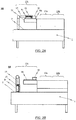
- FIG. 2A Shows in detail FIG. 2A schematically and in a side view an exemplary embodiment of the loading system 10 according to the invention in a first state in which a manipulator 14 of the loading system 10 is in its starting position or waiting position.
- the starting position or waiting position of the at least one manipulator 14 of the third loading arrangement 13c is selected in such a way that only washware parts 9c of the third washware group but not washware parts 9a, 9b of the first or second washware group during transport with the feed conveyor belt 11 into the gripping area of the at least one gripping tongs be promoted.
- the gripper system 15 of the at least one manipulator 14 of the third loading arrangement 13c is assigned a sensor system which is designed to detect when at least one wash ware part 9a, 9b, 9c and in particular at least one wash ware part 9c of the third wash ware group is in the gripping area of the at least one gripper is located.
- the loading system 10 is preferably assigned a control device which is designed to initiate gripping of the at least one gripping tongs when the sensor system assigned to the gripper system 15 detects that at least one wash ware part 9a, 9b, 9c and in particular at least one wash ware part 9c of the third wash ware group is located in the gripping area of the at least one gripping tongs.
- control device is preferably also designed to control the at least one manipulator 14 of the third loading arrangement 13c in such a way that it removes the at least one item of washware gripped by the gripper system 15 from the feed conveyor belt 11 and places it in a predetermined or determinable dedicated position .
- FIG. 2 B schematically and in a side view the loading system 10 according to FIG FIG. 2A in a second state in which the manipulator 14 of the loading system 10 is in its loading position.
- the gripper system 15 of the at least one manipulator 14 of the third loading arrangement 13c is assigned a positioning aid which has at least one guide element, the at least one guide element being formed, preferably only washware 9c of the third washware group, which is via the Feed conveyor belt 11 is fed to steer in the direction of the gripping area of the at least one gripping tongs of the gripper system 15.
- the gripper system 15 is assigned a preferably optically operating detection system 16 for the automatic detection of items 9a, 9b, 9c, in particular items 9c of the third group of items to be washed, fed via the feed conveyor belt 11.
- a preferably optically operating detection system 16 for the automatic detection of items 9a, 9b, 9c, in particular items 9c of the third group of items to be washed, fed via the feed conveyor belt 11.
- FIG. 3A schematically and in a side view an exemplary embodiment of the loading system 10 according to the invention in a first state in which a manipulator 14 of the loading system 10 is in its starting position or recognition position.
- FIG. 3B schematically and in a side view the loading system 10 according to FIG FIG. 3A in a second state in which the manipulator 14 of the loading system 10 is in its loading position.
- control device assigned to the loading system 10 should be designed to move the manipulator 14 of the third loading arrangement 13c with the gripper system 15 to the wash ware part 9c when, with the detection system 16, in particular a wash ware part 9c of the third wash ware group in the one fed via the feed conveyor belt 11 Wash items 9a, 9b, 9c is recognized.
- the starting position of the manipulator 14 is in each case arranged above the feed conveyor belt 11.
- the manipulator 14 is equipped with the gripper system 15.
- the solution shown is the gripper system 15 itself equipped with a sensor, which the presence of items 9a, 9b, 9c and in particular items 9c of the third group of items to be washed are detected in the gripping area of the at least one gripper of gripper system 15.
- the manipulator 14 removes the wash ware part 9c from the tray 9b.
- the wash ware part 9c is then ideally sorted into the main conveyor belt 2 of the conveyor dishwasher 1.
- the manipulator 14 performs a pivoting movement, for example, and places the wash ware part 9c parallel to the transport compartments into which the main conveyor belt 2 is divided. If there is a transport compartment below the wash ware part 9c, the gripper of the gripper system 15 opens and loads the wash ware part 9c into the main conveyor belt 2 (cf. FIG. 2 B ).
- the manipulator 14 can alternatively place the wash ware part 9c on a dedicated storage area and thus form a stack of dishes. This can then be sorted into the main conveyor belt 2 by the operating personnel.
- an additional positioning aid can be integrated which aligns the items to be washed 9c on the tray.
- the manipulator 14 can thus grip the items to be washed 9c more efficiently and remove them from the tray 9b.
- the first solution shown schematically is in the case of the FIGS. 3A and 3B
- the second solution shown is the starting position of the manipulator 14 above the feed conveyor belt 11.
- the gripper system 15 is according to FIG. 3A a preferably optically operating detection system 16 is assigned for the automatic detection of items 9a, 9b, 9c, in particular items 9c of the third group of items to be washed, which are supplied via the feed conveyor belt 11.
- the optically operating detection system 16 can be designed as a camera system with which the gripper system 15 of the Manipulator 14 is equipped. With the aid of this optically operating recognition system 16 or camera system, the items 9c and their position on the trays 9b, which are continuously conveyed to the feed area of the conveyor dishwasher 1 via the feed conveyor belt 11, are recognized.
- a control device is provided which is designed to move the manipulator 14 of the third loading arrangement 13c with the gripper system 15 to the wash ware part 9c when, with the detection system 16, a wash ware part 9c of the third wash ware group in the wash ware 9a, 9b fed via the feed conveyor belt 11 , 9c is recognized.
- the manipulator arm is in its waiting or detection position above the feed conveyor belt 11 (cf. FIG. 3A ).
- the positions of the individual crockery items 9c are first detected.
- the manipulator 14 then automatically positions itself on a corresponding piece of crockery 9c. With the aid of the optically operating recognition system 16, it is ensured that the crockery item 9c is correctly picked up and locked by the gripper system 15.
- the manipulator 14 removes the wash ware part 9c from the tray 9b.
- the wash ware part 9c is then ideally sorted into the main conveyor belt 2 of the conveyor dishwasher 1.
- the manipulator 14 performs a pivoting movement and places the wash ware part 9c parallel to the transport compartments into which the main conveyor belt 2 is divided. If there is a transport compartment below the crockery item, the gripper system 15 opens and loads the crockery item 9c into the main conveyor belt (cf. FIG. 3B ).
- an additional positioning aid can also be integrated here to hold the items to be washed 9c aligns on the tray 9b.
- the manipulator 14 can thus grip the items to be washed 9c more efficiently and take them off the tray 9b.
- the combination of gripper system 15 and optically operating detection system 16 / camera system has the advantage that the items to be washed 9c are detected by the optically operating detection system 16 / camera system before each gripping.
- additional work steps can be carried out by the operating personnel, such as removing waste from the place settings, removing glasses from the trays, and loading additional items, such as items from the fourth or fifth group of items from the tray directly into the conveyor dishwasher 1 and items of cutlery 9a among other things to bring out items to be washed.
- the detection system 16 detects the items 9c of the items to be washed, which are conveyed to the conveyor dishwasher 1 on the supply conveyor belt 11.
- the dishes 9c are removed from the manipulator 14.
- the items to be washed 9c can move, with the result that the manipulator 14 cannot remove the items to be washed from the tray 9b.
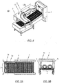
- FIG. 4th is shown schematically and in an isometric view of the loading area of a conveyor dishwasher 1 with an exemplary embodiment of the loading system 10 according to the invention, in which for automatic loading of a conveyor belt parallel to a main conveyor of the conveyor dishwasher 1 running tray track 4 a corresponding loading arrangement 13b (second loading arrangement) is used.
- a corresponding loading arrangement 13b second loading arrangement
- FIG. 5A and FIG. 5B show schematically and in a top view ( FIG. 5A ) and in a cross-sectional view ( FIG. 5B ) the main conveyor belt 2 and the parallel tray track 4 of the conveyor dishwasher 1 according to FIG FIG. 4th .
- FIG. 6th is shown schematically and in an isometric view of the loading area of a conveyor dishwasher 1, specifically together with a first and a second loading arrangement 13a, 13b, which are assigned to the sorting arrangement of the loading system 10 according to the invention.
- the first loading arrangement 13a serves to automatically load the conveyor dishwasher 1 with washware 9a of the first washware group, ie with cutlery and / or cutlery made from a metal, in particular stainless steel.
- FIG. 7A and FIG. 7B show schematically and in a top view ( FIG. 7A ) and in a cross-sectional view ( FIG. 7B ) the main conveyor belt 2 and the tray and cutlery tracks 4, 3 of the conveyor dishwasher 1 running parallel to it FIG. 6th .
- the first loading arrangement 13a is arranged upstream of the second loading arrangement 13b, as seen in the transport direction of the feed conveyor belt 11.
- the second loading arrangement 13b is used to automatically load washware 9b of the second washware group into the conveyor dishwasher 1.
- the first conveyor belt 4 is made relatively narrow compared to the third conveyor belt 2, so that a tray or tray-like wash ware 9b can only be picked up by the first conveyor belt 4 in an upright position and oriented parallel to the transport direction.
- the orientation of the of that Wash ware 9b to be received on the first conveyor belt 4 parallel to the running direction of the first conveyor belt 4 requires a minimal use of the total area of the belt.
- the first conveyor belt 4 has such a reduced width that only a minimal area of the total belt surface is occupied by the first conveyor belt 4, which precisely allows trays or tray-like items to be washed 9b when these items to be washed 9b are placed on edge State and oriented parallel to the transport direction.
- the second conveyor belt 3 which is designed as a cutlery conveyor belt, also has a reduced width compared to the third conveyor belt 2.
- the third conveyor belt 2 still has a sufficient width to be used almost without restrictions for the transport of wash items 9c of the third wash item group, in particular plates, bowls and / or glasses, through the individual treatment zones of the conveyor dishwashers remain.
- Glass baskets or GN containers can still be placed on the third conveyor belt 2 next to the tray or tray-like items 9b received on the first conveyor belt.
- FIG. 4th and FIG. 6th only a part of the sorting arrangement is shown in each case, namely that region of the sorting arrangement which - viewed in the transport direction of the feed belt - is arranged behind the third loading arrangement 13a, 13b, 13c.
- the first loading arrangement 13a according to FIG. 4th and FIG. 6th
- the place setting sets are supplied via the feed conveyor belt 11, in which the wash items 9c of the third group of wash items are automatically fed with the help of the (in FIG. 4th and FIG. 6th not shown) third loading arrangement 13c was removed.
- the cutlery 9a is removed from the trays 9b with the aid of a cutlery lifting magnet in the form of a controllable magnet 17 and the cutlery items 9a are then automatically placed in the cutlery lane 3 of the conveyor dishwasher 1.
- the tray 9b is then conveyed to the infeed device of the second loading arrangement 13b, where it is automatically placed in the corresponding tray lane 4 of the conveyor dishwasher 1 (cf. FIG. 6th ).
- the infeed device has a corresponding guide 18 via which the trays 9b are automatically transferred from their horizontal state to an upright state and then introduced into the corresponding tray lane 4 of the conveyor dishwasher 1.
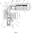
- FIG. 8th an exemplary embodiment of the conveyor dishwasher arrangement according to the invention is described. Shows in detail FIG. 8th schematically and in a top view the loading areas of a conveyor dishwasher arrangement comprising two conveyor dishwashers with an exemplary embodiment of the loading system according to the invention.
- conveyor dishwashers 1, 1 ' each having at least one conveyor track 2, 3, 4, different conveyor tracks 2, 3, 4 are provided for different types of wash ware.
- FIG. 8th The conveyor dishwasher arrangement shown schematically also has a loading system 10 which, in structural and functional terms, has the above with reference FIG. 1 described loading system 10 corresponds.
- the sorting arrangement of the loading system 10 is assigned a first loading arrangement 13a for automatically loading a first transport lane 2 of the two conveyor dishwashers 1, 1 'with wash items 9a of the first wash item group, with the sorting arrangement preferably being assigned a second loading arrangement 13b for automatically loading a second transport lane 3 of the two conveyor dishwashers 1, 1 'with wash ware 9b of the second wash ware group, and wherein the sorting arrangement is preferably assigned a third loading arrangement 13c for automatically loading a third transport lane 4 of the two transport dishwashers 1, 1' with wash ware 9c of the third group of items to be washed.
- first and second transport lanes 2, 3 are part of a transport device of a first conveyor dishwasher 1, while the third transport lane 4 is part of a transport device of a second conveyor dishwasher 1 '.
Landscapes
- Engineering & Computer Science (AREA)
- Mechanical Engineering (AREA)
- Robotics (AREA)
- Washing And Drying Of Tableware (AREA)
Applications Claiming Priority (1)
| Application Number | Priority Date | Filing Date | Title |
|---|---|---|---|
| DE102020112090.7A DE102020112090A1 (de) | 2020-05-05 | 2020-05-05 | System zum beladen von unterschiedlichen transportspuren mindestens einer spülmaschine und spülmaschinenanordnung mit einem derartigen system |
Publications (2)
| Publication Number | Publication Date |
|---|---|
| EP3906834A1 true EP3906834A1 (fr) | 2021-11-10 |
| EP3906834B1 EP3906834B1 (fr) | 2025-12-17 |
Family
ID=75801429
Family Applications (1)
| Application Number | Title | Priority Date | Filing Date |
|---|---|---|---|
| EP21171937.2A Active EP3906834B1 (fr) | 2020-05-05 | 2021-05-04 | Système de chargement de différentes voies de transport d'au moins une bobinoir et agencement de bobinoir doté d'un tel système |
Country Status (6)
| Country | Link |
|---|---|
| US (1) | US11608233B2 (fr) |
| EP (1) | EP3906834B1 (fr) |
| JP (1) | JP2021176510A (fr) |
| CN (1) | CN113598680A (fr) |
| AU (1) | AU2021202663A1 (fr) |
| DE (1) | DE102020112090A1 (fr) |
Families Citing this family (4)
| Publication number | Priority date | Publication date | Assignee | Title |
|---|---|---|---|---|
| CN114287856B (zh) * | 2022-01-27 | 2025-05-27 | 薛晨阳 | 一种餐饮业成套餐具的批量清洗组装设备及其使用方法 |
| JP7528138B2 (ja) * | 2022-03-01 | 2024-08-05 | 北沢産業株式会社 | 洗浄システム |
| DE102024202128A1 (de) * | 2024-03-07 | 2025-09-11 | Meiko Maschinenbau Gmbh & Co. Kg | Transportsystem und Verfahren zum automatischen Transport von Reinigungsgut |
| DE102024211048A1 (de) | 2024-11-18 | 2026-05-21 | Meiko Maschinenbau Gmbh & Co. Kg | Sortiervorrichtung zum Sortieren von Reinigungsgut |
Citations (4)
| Publication number | Priority date | Publication date | Assignee | Title |
|---|---|---|---|---|
| US3486939A (en) * | 1967-10-17 | 1969-12-30 | Charles P Pinckard | Apparatus for classifying,cleaning and collecting culinary items |
| US6530996B2 (en) | 2000-07-13 | 2003-03-11 | Fuuga-Controls Oy | Method for washing items |
| US20100043834A1 (en) * | 2008-08-22 | 2010-02-25 | Stefan Scheringer | Dishwasher with a handling device at the dish deposit point |
| EP2720597B1 (fr) * | 2011-06-16 | 2016-02-03 | Kampri Support B.V. | Procédé et système de nettoyage de vaisselle, à l'aide d'un système de vision électronique et un manipulateur |
Family Cites Families (7)
| Publication number | Priority date | Publication date | Assignee | Title |
|---|---|---|---|---|
| DE102008057178A1 (de) * | 2008-11-13 | 2010-05-20 | Premark Feg L.L.C., Wilmington | Anlage zum Spülen von Spülgut und Verfahren zum Betreiben einer solchen Anlage |
| DE102010062471A1 (de) * | 2010-12-06 | 2012-06-06 | Premark Feg L.L.C. | Transportspülmaschine |
| DE102011004853B4 (de) * | 2011-02-28 | 2014-11-27 | Premark Feg L.L.C. (N.D.Ges.D. Staates Delaware) | Fördervorrichtung zum Zuführen von Spülgut an eine Transportspülmaschine |
| WO2018034251A1 (fr) * | 2016-08-14 | 2018-02-22 | ライフロボティクス株式会社 | Système de lavage de vaisselle et dispositif robot |
| CN109157175A (zh) * | 2018-09-29 | 2019-01-08 | 宁波超胜商用厨房设备有限公司 | 餐具自动清洗回收系统 |
| CN209153513U (zh) * | 2018-09-29 | 2019-07-26 | 宁波超胜商用厨房设备有限公司 | 餐具自动清洗回收系统 |
| DE102018217052A1 (de) * | 2018-10-05 | 2020-04-09 | Meiko Maschinenbau Gmbh & Co. Kg | Reinigungsvorrichtung und Verfahren zur Reinigung von Reinigungsgut |
-
2020
- 2020-05-05 DE DE102020112090.7A patent/DE102020112090A1/de active Pending
-
2021
- 2021-04-28 US US17/243,108 patent/US11608233B2/en active Active
- 2021-04-29 CN CN202110478255.9A patent/CN113598680A/zh active Pending
- 2021-04-29 AU AU2021202663A patent/AU2021202663A1/en not_active Abandoned
- 2021-04-30 JP JP2021077302A patent/JP2021176510A/ja active Pending
- 2021-05-04 EP EP21171937.2A patent/EP3906834B1/fr active Active
Patent Citations (4)
| Publication number | Priority date | Publication date | Assignee | Title |
|---|---|---|---|---|
| US3486939A (en) * | 1967-10-17 | 1969-12-30 | Charles P Pinckard | Apparatus for classifying,cleaning and collecting culinary items |
| US6530996B2 (en) | 2000-07-13 | 2003-03-11 | Fuuga-Controls Oy | Method for washing items |
| US20100043834A1 (en) * | 2008-08-22 | 2010-02-25 | Stefan Scheringer | Dishwasher with a handling device at the dish deposit point |
| EP2720597B1 (fr) * | 2011-06-16 | 2016-02-03 | Kampri Support B.V. | Procédé et système de nettoyage de vaisselle, à l'aide d'un système de vision électronique et un manipulateur |
Also Published As
| Publication number | Publication date |
|---|---|
| JP2021176510A (ja) | 2021-11-11 |
| AU2021202663A1 (en) | 2021-11-25 |
| US20210347585A1 (en) | 2021-11-11 |
| DE102020112090A1 (de) | 2021-11-11 |
| EP3906834B1 (fr) | 2025-12-17 |
| CN113598680A (zh) | 2021-11-05 |
| US11608233B2 (en) | 2023-03-21 |
Similar Documents
| Publication | Publication Date | Title |
|---|---|---|
| EP3906834B1 (fr) | Système de chargement de différentes voies de transport d'au moins une bobinoir et agencement de bobinoir doté d'un tel système | |
| DE102019102800A1 (de) | System zum Beladen einer Spülmaschine und Spülmaschine mit einem derartigen System | |
| DE102011004853B4 (de) | Fördervorrichtung zum Zuführen von Spülgut an eine Transportspülmaschine | |
| EP3107843B1 (fr) | Procédé et poste de préparation de commandes d'articles selon le principe 'marchandise vers homme' | |
| DE102008014318B4 (de) | Transportspülmaschine und Verfahren zum Betreiben einer Transportspülmaschine | |
| DE102010062457A1 (de) | Beladevorrichtung für eine Transportspülmaschine | |
| DE102012203839B4 (de) | Abstapelsystem für Transportspülmaschinen | |
| EP2158833A2 (fr) | Lave-vaisselle doté d'un appareil de manipulation sur le plateau à vaisselle | |
| DE102010062471A1 (de) | Transportspülmaschine | |
| DE102015214300A1 (de) | Transportspülmaschine sowie Verfahren zum Betreiben einer Transportspülmaschine | |
| EP3840626B1 (fr) | Système de nettoyage et procédé de nettoyage de produit à nettoyer | |
| DE102020214604A1 (de) | Sortiersystem zum Sortieren von Besteckteilen | |
| EP3915456B1 (fr) | Système de chargement de vaisselles dans au moins un lave-vaisselle mobile, agencement d'au moins un lave-vaisselle mobile et d'un système de chargement, ainsi que procédé de chargement de vaisselles dans au moins un lave-vaisselle mobile | |
| EP3860419B1 (fr) | Dispositif de nettoyage et procédé de nettoyage d'articles à nettoyer | |
| EP3970592A1 (fr) | Système de chargement d'un lave-vaisselle, système de préhension pour un dispositif de chargement permettant de charger un lave-vaisselle, ainsi que lave-vaisselle | |
| DE102019102813A1 (de) | Entladeanordnung zum Entladen von insbesondere auf Tabletts oder tablettartigen Gegenständen angeordneten Spülgutteilen | |
| DE2214196A1 (de) | Verfahren zum Behandeln von schmutzigen Geschirrtellen und Vorrichtung zur Aus übung des Verfahrens | |
| DE102022112518B4 (de) | Transportvorrichtung für eine spülmaschine sowie spülmaschine mit einer solchen transportvorrichtung | |
| DE102020104654A1 (de) | System zum beladen einer transportspülmaschine | |
| EP3870015B1 (fr) | Système de nettoyage et procédé de nettoyage d'article à nettoyer | |
| DE102024102560A1 (de) | Beladesystem zum beladen einer transportspülmaschine mit spülgutteilen sowie anordnung zum zumindest teilautomatisierten reinigen von spülgutteilen mit einem beladesystem | |
| DE102021106853A1 (de) | Verfahren und system zum vorzugsweise automatischen reinigen von tabletts in einer spülmaschine | |
| DE102023202231A1 (de) | Entnahmemodul und Verfahren zum Entnehmen von Spülgut | |
| DE102012025940B4 (de) | Abstapelsystem für Transportspülmaschinen | |
| DE102019210272A1 (de) | Reinigungsvorrichtung mit Korbrückführung |
Legal Events
| Date | Code | Title | Description |
|---|---|---|---|
| PUAI | Public reference made under article 153(3) epc to a published international application that has entered the european phase |
Free format text: ORIGINAL CODE: 0009012 |
|
| STAA | Information on the status of an ep patent application or granted ep patent |
Free format text: STATUS: REQUEST FOR EXAMINATION WAS MADE |
|
| 17P | Request for examination filed |
Effective date: 20210504 |
|
| AK | Designated contracting states |
Kind code of ref document: A1 Designated state(s): AL AT BE BG CH CY CZ DE DK EE ES FI FR GB GR HR HU IE IS IT LI LT LU LV MC MK MT NL NO PL PT RO RS SE SI SK SM TR |
|
| B565 | Issuance of search results under rule 164(2) epc |
Effective date: 20210924 |
|
| STAA | Information on the status of an ep patent application or granted ep patent |
Free format text: STATUS: EXAMINATION IS IN PROGRESS |
|
| 17Q | First examination report despatched |
Effective date: 20231023 |
|
| GRAP | Despatch of communication of intention to grant a patent |
Free format text: ORIGINAL CODE: EPIDOSNIGR1 |
|
| STAA | Information on the status of an ep patent application or granted ep patent |
Free format text: STATUS: GRANT OF PATENT IS INTENDED |
|
| RIC1 | Information provided on ipc code assigned before grant |
Ipc: A47L 15/24 20060101AFI20250722BHEP Ipc: B25J 11/00 20060101ALI20250722BHEP Ipc: A47L 15/00 20060101ALI20250722BHEP Ipc: A47L 15/42 20060101ALN20250722BHEP |
|
| INTG | Intention to grant announced |
Effective date: 20250805 |
|
| GRAS | Grant fee paid |
Free format text: ORIGINAL CODE: EPIDOSNIGR3 |
|
| GRAA | (expected) grant |
Free format text: ORIGINAL CODE: 0009210 |
|
| STAA | Information on the status of an ep patent application or granted ep patent |
Free format text: STATUS: THE PATENT HAS BEEN GRANTED |
|
| AK | Designated contracting states |
Kind code of ref document: B1 Designated state(s): AL AT BE BG CH CY CZ DE DK EE ES FI FR GB GR HR HU IE IS IT LI LT LU LV MC MK MT NL NO PL PT RO RS SE SI SK SM TR |
|
| REG | Reference to a national code |
Ref country code: CH Ref legal event code: F10 Free format text: ST27 STATUS EVENT CODE: U-0-0-F10-F00 (AS PROVIDED BY THE NATIONAL OFFICE) Effective date: 20251217 Ref country code: GB Ref legal event code: FG4D Free format text: NOT ENGLISH |
|
| P01 | Opt-out of the competence of the unified patent court (upc) registered |
Free format text: CASE NUMBER: UPC_APP_0013725_3906834/2025 Effective date: 20251118 |
|
| REG | Reference to a national code |
Ref country code: DE Ref legal event code: R096 Ref document number: 502021009420 Country of ref document: DE |
|
| REG | Reference to a national code |
Ref country code: LT Ref legal event code: MG9D |
|
| PG25 | Lapsed in a contracting state [announced via postgrant information from national office to epo] |
Ref country code: NO Free format text: LAPSE BECAUSE OF FAILURE TO SUBMIT A TRANSLATION OF THE DESCRIPTION OR TO PAY THE FEE WITHIN THE PRESCRIBED TIME-LIMIT Effective date: 20260317 |
|
| PG25 | Lapsed in a contracting state [announced via postgrant information from national office to epo] |
Ref country code: HR Free format text: LAPSE BECAUSE OF FAILURE TO SUBMIT A TRANSLATION OF THE DESCRIPTION OR TO PAY THE FEE WITHIN THE PRESCRIBED TIME-LIMIT Effective date: 20251217 Ref country code: FI Free format text: LAPSE BECAUSE OF FAILURE TO SUBMIT A TRANSLATION OF THE DESCRIPTION OR TO PAY THE FEE WITHIN THE PRESCRIBED TIME-LIMIT Effective date: 20251217 |
|
| PG25 | Lapsed in a contracting state [announced via postgrant information from national office to epo] |
Ref country code: RS Free format text: LAPSE BECAUSE OF FAILURE TO SUBMIT A TRANSLATION OF THE DESCRIPTION OR TO PAY THE FEE WITHIN THE PRESCRIBED TIME-LIMIT Effective date: 20260317 |
|
| REG | Reference to a national code |
Ref country code: NL Ref legal event code: MP Effective date: 20251217 |
|
| PG25 | Lapsed in a contracting state [announced via postgrant information from national office to epo] |
Ref country code: LV Free format text: LAPSE BECAUSE OF FAILURE TO SUBMIT A TRANSLATION OF THE DESCRIPTION OR TO PAY THE FEE WITHIN THE PRESCRIBED TIME-LIMIT Effective date: 20251217 |
|
| PG25 | Lapsed in a contracting state [announced via postgrant information from national office to epo] |
Ref country code: BG Free format text: LAPSE BECAUSE OF FAILURE TO SUBMIT A TRANSLATION OF THE DESCRIPTION OR TO PAY THE FEE WITHIN THE PRESCRIBED TIME-LIMIT Effective date: 20251217 |