EP3906847A1 - Verfahren, vorrichtung und system zur bestimmung einer verschiebung des herzzeitvolumens - Google Patents
Verfahren, vorrichtung und system zur bestimmung einer verschiebung des herzzeitvolumens Download PDFInfo
- Publication number
- EP3906847A1 EP3906847A1 EP21382412.1A EP21382412A EP3906847A1 EP 3906847 A1 EP3906847 A1 EP 3906847A1 EP 21382412 A EP21382412 A EP 21382412A EP 3906847 A1 EP3906847 A1 EP 3906847A1
- Authority
- EP
- European Patent Office
- Prior art keywords
- time
- plethysmographic
- plethysmographic signal
- user
- cardiac output
- Prior art date
- Legal status (The legal status is an assumption and is not a legal conclusion. Google has not performed a legal analysis and makes no representation as to the accuracy of the status listed.)
- Granted
Links
Images


Classifications
-
- A—HUMAN NECESSITIES
- A61—MEDICAL OR VETERINARY SCIENCE; HYGIENE
- A61B—DIAGNOSIS; SURGERY; IDENTIFICATION
- A61B5/00—Measuring for diagnostic purposes; Identification of persons
- A61B5/02—Detecting, measuring or recording for evaluating the cardiovascular system, e.g. pulse, heart rate, blood pressure or blood flow
- A61B5/021—Measuring pressure in heart or blood vessels
- A61B5/022—Measuring pressure in heart or blood vessels by applying pressure to close blood vessels, e.g. against the skin; Ophthalmodynamometers
-
- A—HUMAN NECESSITIES
- A61—MEDICAL OR VETERINARY SCIENCE; HYGIENE
- A61B—DIAGNOSIS; SURGERY; IDENTIFICATION
- A61B5/00—Measuring for diagnostic purposes; Identification of persons
- A61B5/02—Detecting, measuring or recording for evaluating the cardiovascular system, e.g. pulse, heart rate, blood pressure or blood flow
- A61B5/026—Measuring blood flow
- A61B5/0295—Measuring blood flow using plethysmography, i.e. measuring the variations in the volume of a body part as modified by the circulation of blood therethrough, e.g. impedance plethysmography
-
- A—HUMAN NECESSITIES
- A61—MEDICAL OR VETERINARY SCIENCE; HYGIENE
- A61B—DIAGNOSIS; SURGERY; IDENTIFICATION
- A61B5/00—Measuring for diagnostic purposes; Identification of persons
- A61B5/02—Detecting, measuring or recording for evaluating the cardiovascular system, e.g. pulse, heart rate, blood pressure or blood flow
- A61B5/026—Measuring blood flow
- A61B5/0261—Measuring blood flow using optical means, e.g. infrared light
-
- A—HUMAN NECESSITIES
- A61—MEDICAL OR VETERINARY SCIENCE; HYGIENE
- A61B—DIAGNOSIS; SURGERY; IDENTIFICATION
- A61B5/00—Measuring for diagnostic purposes; Identification of persons
- A61B5/02—Detecting, measuring or recording for evaluating the cardiovascular system, e.g. pulse, heart rate, blood pressure or blood flow
- A61B5/026—Measuring blood flow
- A61B5/029—Measuring blood output from the heart, e.g. minute volume
-
- A—HUMAN NECESSITIES
- A61—MEDICAL OR VETERINARY SCIENCE; HYGIENE
- A61B—DIAGNOSIS; SURGERY; IDENTIFICATION
- A61B5/00—Measuring for diagnostic purposes; Identification of persons
- A61B5/72—Signal processing specially adapted for physiological signals or for diagnostic purposes
- A61B5/7235—Details of waveform analysis
- A61B5/7239—Details of waveform analysis using differentiation including higher order derivatives
-
- A—HUMAN NECESSITIES
- A61—MEDICAL OR VETERINARY SCIENCE; HYGIENE
- A61B—DIAGNOSIS; SURGERY; IDENTIFICATION
- A61B5/00—Measuring for diagnostic purposes; Identification of persons
- A61B5/72—Signal processing specially adapted for physiological signals or for diagnostic purposes
- A61B5/7235—Details of waveform analysis
- A61B5/7242—Details of waveform analysis using integration
-
- A—HUMAN NECESSITIES
- A61—MEDICAL OR VETERINARY SCIENCE; HYGIENE
- A61B—DIAGNOSIS; SURGERY; IDENTIFICATION
- A61B5/00—Measuring for diagnostic purposes; Identification of persons
- A61B5/02—Detecting, measuring or recording for evaluating the cardiovascular system, e.g. pulse, heart rate, blood pressure or blood flow
- A61B5/021—Measuring pressure in heart or blood vessels
- A61B5/022—Measuring pressure in heart or blood vessels by applying pressure to close blood vessels, e.g. against the skin; Ophthalmodynamometers
- A61B5/02233—Occluders specially adapted therefor
Definitions
- Haemodynamic monitoring and specifically a shift in cardiac output, is a very relevant aspect in the care and monitoring of a patient's progress, since it enables information about his or her cardiocirculatory physiopathology to be obtained.
- the pulmonary artery catheter (PAC) has been the most widely used technique since its introduction more than 40 years ago. Although its role in better understanding cardiovascular function is undisputed, its use has declined due to controversy surrounding its indications and limitations, as well as its obvious invasiveness. For this reason, the search for new monitoring methods has intensified.
- PAC pulmonary artery catheter
- patent document ES2587789 discloses a portable device capable of measuring blood pressure and an electrocardiogram, operated by the patient him or herself, which can communicate the results to a server or platform with automatic data storage and analysis services to detect problems and alert the doctor. All information is accessed by the corresponding authorised persons such as doctors, the patient him or herself or family members, thus allowing continuous monitoring of the patient and his or her progress.
- this device is not able to monitor cardiac output, in other words, the haemodynamic status of the patient.
- patent document EP1173093 discloses a method that obtains an absolute value of cardiac output from the blood pressure signal measured invasively (in the ascending aorta, in the pulmonary artery and in the brachial, femoral and radial artery), or measured non-invasively, for example, in the arteriole of a finger, using an extremely fast pressure actuator to compensate for pressure variations in the arteriole and achieve a flat photoplethysmographic response.
- This method uses, on the one hand, an electromechanical mechanism that is more complex and has a faster response than the one herein proposed according to the invention, which is very sensitive to movements and tends to underestimate blood pressure, and on the other hand, a calculation method that analyses the first and second derivatives with respect to the time of the pressure signal, which requires a certain high computing capacity.
- the present invention contributes to finding solutions and solving the existing drawback.
- An object of the present invention is to provide a computer-implemented method by means of which a shift in cardiac output is determined from plethysmographic signals.
- a plethysmographic signal also called PS, refers to the intensity of light reflected and/or transmitted by a user's body, preferably by the arm or finger, coming from LED light emitted with a determined wavelength.
- the LED light can be emitted through an LED emitting device and the light reflected and/or transmitted by a user's body can be captured through a light detector.
- the light detector can obtain the plethysmographic signal.
- the pressure value that is applied to the user when the plethysmographic signal is being measured can also be called the output pressure measurement (OPM).
- OPM output pressure measurement
- the blood volume decreases to its normal levels and, if light is applied to the same part of the body on which light was previously applied, the plethysmographic signal recovers approximately the value prior to the application of pressure.
- the basis of the present invention is the comparison of plethysmographic signals obtained in spans of time during which an output pressure measurement has been applied to the user in order to determine the shift in cardiac output based on the processing of the data obtained.
- the computer-implemented method starts with a first plethysmographic signal obtained in a first span of time in which at least one first period of time is included during which an output pressure measurement has been applied to the user that is higher than venous pressure and lower than systolic pressure, and a second plethysmographic signal in a second span of time, some time after the first span of time, in which at least one second period of time is included during which an output pressure measurement has been applied to the user that is higher than venous pressure and lower than systolic pressure.
- Said computer-implemented method comprises at least one step in which the shift in cardiac output is determined from at least one of the following parameters: slopes of the first and second plethysmographic signals at the loading point, magnitude of the fall of the plethysmographic signals in a first time interval and areas of the regions that lie between the line parallel to the x-axis at a height coinciding with the ordinate of the loading point and the plethysmographic signal in a second time interval; at least part of the first interval being within the first and second periods of time and part of the second interval being within the first and second periods of time within the first and second periods of time.
- the first parameter of the plethysmographic signal from which the shift in cardiac output can be determined is the slope, Sc, of the signal at the loading point.
- the loading point is understood to be the starting point of the plethysmographic signal from which the decrease of the plethysmographic signal begins in the period of time during which the output pressure measurement has been applied to the user.
- the difference in the slopes of the second plethysmographic signal and the first plethysmographic signal at the respective loading points thereof is negative, it is considered that there has been an increase in cardiac output, while if said difference is positive, it indicates that there has been a decrease in cardiac output.
- the second parameter of those mentioned is the magnitude of the fall of the plethysmographic signals in a first time interval.
- Said fall can also be called PSf or PS fall and the time interval is preferably defined from the loading point.
- PSf PS 0 -PS(t f +t 0 ); where PSo is the value of the plethysmographic signal at time t 0 , in other words, the ordinate of the loading point.
- a value of PS could be taken as a value of PSo at a time prior to that of the abscissa of the loading point (in other words, a time prior to applying the output pressure measurement).
- this prior time for the first plethysmographic signal is the same as the one for the second plethysmographic signal, in other words, they are at the same temporal distance from the abscissa of the loading point.
- a mean value of the plethysmographic signal could also be taken as a value of PSo during the moments in times prior, preferably 5 s, to the abscissa of the loading point (in other words, a few moments in time prior to applying the output pressure measurement).
- These moments in time define a time frame where, preferably, the first time interval is defined from the last moment in time of the time frame (time to).
- these prior moments in time for the first plethysmographic signal are the same as those for the second plethysmographic signal, in other words, they are at the same temporal distance from the abscissa of the loading point.
- t f can take different values, preferably in the range of 20 to 50 s and more preferably the value of 40 s. This means that the value of the first time interval is between 20 to 50 s and more preferably 40 s.
- the difference in the fall of the second plethysmographic signal and the first plethysmographic signal in a first time interval is negative, it is considered that there has been a decrease in cardiac output, while if said difference is positive, it indicates that there has been an increase in cardiac output.
- the third parameter consists of the areas of the regions that lie between the line parallel to the x-axis at a height coinciding with the ordinate of the loading point and the plethysmographic signal in a second time interval.
- the duration of the second time interval can take different values, preferably in the range of 20 to 50 s and more preferably the value of 40 s.
- the areas can delimit the regions that lie between the line parallel to the x-axis at a height coinciding with the ordinate of the loading point and the plethysmographic signal from the abscissae of the loading points thereof up to 40 seconds later.
- the second interval is defined from the abscissa of the loading point.
- duration of the first time interval can be the same as that of the second time interval.
- this third parameter based on the mentioned areas can be specified from the difference in the previously defined areas of each of the plethysmographic signals in said second time interval. Consequently, the difference in areas would be defined as subtraction between
- the shift in cardiac output can be determined based on the combination of the result of the shift in output obtained by two or three of these parameters (slopes at the loading point, magnitude of the fall of the plethysmographic signals in the first time interval and/or area of the regions that lie between the line parallel to the x-axis at a height coinciding with the ordinate of the loading point and the plethysmographic signal in a second time interval), each one of them being properly weighted to provide a final decision on the shift in cardiac output (it increases or decreases).
- one possible weighting would be that if the 3 parameters coincide in their assessment of the shift in cardiac output (in other words, all 3 determine that there has been an increase or decrease in cardiac output), there is maximum confidence in the result. If the parameters consisting of the magnitude of the fall of the plethysmographic signals in a first time interval and the areas of the regions that lie between the line parallel to the x-axis at a height coinciding with the ordinate of the loading point and the plethysmographic signal in a second time interval coincide in their assessment of the shift in cardiac output but differ with respect to the assessment offered by the parameter consisting of the slope at the loading point, they should be weighted so that the result offers confidence that is high but lower than the previous situation where the 3 parameters coincided in the assessment of the output.
- the parameters consisting of the magnitude of the fall of the plethysmographic signals in a first time interval and the areas of the regions that lie between the line parallel to the x-axis at a height coinciding with the ordinate of the loading point and the plethysmographic signal in a second time interval do not coincide in their assessment of the shift in cardiac output (in other words, one of them determines that there has been an increase in cardiac output and another determines that there has been a decrease), the parameter of the slopes at the loading point could be used to decide on the assessment of the shift in cardiac output.
- the computer-implemented method can comprise a step, preferably prior to the previous step, consisting of normalising the plethysmographic signals.
- Such normalisation can be carried out by dividing the plethysmographic signal by its value at the abscissa of the loading point (in other words, at the time when the output pressure measurement is applied) or by its value at a time prior to the abscissa of the loading point (in other words, at a time prior to applying the outlet measurement pressure) or by the mean value of the plethysmographic signal during the moments in time prior, preferably 5 s, to the abscissa of the loading point (in other words, a few moments in time prior to applying the output pressure measurement).
- Normalisation enables measurements taken under different circumstances to be compared with one same parameter on one same scale, offering more reliable results that are less dependent on conditions or external factors such as the pressure or area on which the device that emits the LED light and the light detector in charge of detecting the LED light are applied.
- the computer-implemented method determines that there is a shift in cardiac output, it will preferably be communicated to the user either through a light or sound signal or with the corresponding interface of the computer on which it is run.
- An object of the present invention is a data processing device comprising means for carrying out the computer-implemented method of the invention.
- the present invention would encompass a computer program comprising instructions that, when the program is run on a computer, cause the computer to carry out the steps of the computer-implemented method of the invention.
- the present invention would also include a computer-readable medium comprising instructions that, when run by a computer, cause the computer to carry out the steps of the computer-implemented method of the invention.
- Another object of the present invention is a method for determining a shift in cardiac output that comprises the following steps:
- the determination step may also consist of determining the shift in cardiac output by means of a data processing device according to the invention, in other words, configured to carry out the computer-implemented method of the invention.
- the shift in cardiac output is determined as set out for the computer-implemented method of the invention.
- the difference in the slopes of the second plethysmographic signal and the first plethysmographic signal at the respective loading points thereof is negative, it is considered that there has been an increase in cardiac output, while if said difference is positive, it indicates that there has been a decrease in cardiac output.
- the duration of this first time interval is in the range of 20 to 50 s and more preferably it is 40 s.
- the fall of the plethysmographic signal can be measured as the difference between the value of the plethysmographic signal at the abscissa of the loading point and the value of the plethysmographic signal at the moment in time consisting of the sum of the abscissa of the loading point and the duration of the first time interval.
- the fall of the plethysmographic signal can be measured as the difference between the value of the plethysmographic signal at a time prior to the abscissa of the loading point and the value of the plethysmographic signal at the end of the first time interval (moment in time resulting from adding the duration of the first time interval to the abscissa of the loading point).
- this prior time for the first plethysmographic signal is the same as the one for the second plethysmographic signal, in other words, they are at the same temporal distance from the abscissa of the respective loading points thereof.
- the fall of the plethysmographic signal can be measured as the difference between the mean value of the plethysmographic signal during moments in time prior, preferably 5 s, to the abscissa of the loading point and the value of the plethysmographic signal at the end of the first time interval.
- These prior moments in time define a time frame where, preferably, the first time interval is defined from the last moment in time of the time frame.
- these prior moments in time for the first plethysmographic signal are the same as those for the second plethysmographic signal, in other words, they are at the same temporal distance from the abscissa of the respective loading points thereof.
- the parameter consisting of the areas of the regions that lie between the line parallel to the x-axis at a height coinciding with the ordinate of the loading point and the plethysmographic signal in a second time interval, it can be determined from the difference in said areas for each of the plethysmographic signals.
- the duration of the second time interval can take different values, preferably in the range of 20 to 50 s and more preferably the value of 40 s.
- the second time interval is defined from the abscissa of the loading point of the corresponding plethysmographic signal.
- duration of the first time interval can be the same as that of the second time interval.
- the shift in cardiac output can be determined based on the combination of two or three of these parameters (slopes at the loading point, magnitude of the fall of the plethysmographic signals in a first time interval and/or areas of the regions that lie between the line parallel to the x-axis at a height coinciding with the ordinate of the loading point and the plethysmographic signal in a second time interval), each of them being properly weighted in the final decision.
- such weighting would be done in such a way that, if the assessment of the shift in cardiac output for each of these parameters is the same, the result should offer maximum confidence.
- the assessment of the shift in cardiac output coincides with the parameters of magnitude of the fall of the plethysmographic signal in a first time interval and areas of the regions that lie between the line parallel to the x-axis at a height coinciding with the ordinate of the loading point and the plethysmographic signal in a second time interval but differs from the assessment of the shift in cardiac output according to the slopes of the plethysmographic signal at the loading point, the result should offer confidence that is acceptable but lower than the previous case.
- the result will be fixed based on the assessment of the shift in cardiac output according to the parameter of the slopes at the loading point. In other words, if according to this parameter the shift in cardiac output is to increase, it will be determined as such, and if according to this parameter the shift in cardiac output is to decrease, it will be established as such.
- the method according to the invention may comprise a step consisting of normalising the plethysmographic signals.
- normalisation can be carried out by dividing the plethysmographic signal by its value at the abscissa of the loading point, or by its value at a time prior to the abscissa of the loading point, or by the mean value of the plethysmographic signal during the moments in time prior, preferably 5s, to the abscissa of the loading point.
- Another object of the present invention is a portable device capable of determining a shift in cardiac output.
- the portable device of the present invention comprises processing means, an air pump, a fluidic connection port linked to the air pump, an LED emitter and a light detector, as well as a power supply to power the processing means, the LED emitter and the light detector.
- the power source is a rechargeable battery.
- the processing means comprise at least one processor or processing device, but may also include storage devices, such as memory drives, necessary to be able to perform calculations required by the processing means.
- the processing means are in data communication with the fluidic connection port and the light detector and can control the air pump and the power supply, as well as the LED emitter.
- the processing means are configured to run the computer-implemented method of the invention mentioned above.
- the portable device comprises a pressure sensor that is in data communication with the processing means.
- an inflatable cuff that is connected to the portable device via the fluidic connection port can be provided with an output pressure measurement higher than the venous pressure and lower than the systolic blood pressure of a user.
- the same portable device can also be configured to measure the user's blood pressure through the corresponding pressure sensor.
- the inflatable cuff may be part of the portable device or it may be an external one of the removable type.
- the LED emitter has been selected to emit light with a predetermined wavelength, preferably within the range of red light to infrared light, and the light detector is capable of detecting the spectrum of light emitted by said LED.
- the LED emitter is in data communication with the processing means such that the processing means decide on the emission of light by the LED emitter.
- the light detector and the processing means are in data communication such that the processing means receive the value of light intensity detected by the light detector, in other words, the plethysmographic signal or PS.
- the processing means obtain the plethysmographic signal over a span of time that includes a period of time during which a pressure of the order of venous pressure and systolic blood pressure (and preferably between the two) has been applied to the user through an inflatable cuff, said pressure being provided by the air pump and the fluidic connection port.
- the processing means is configured to determine the shift in cardiac output by running the computer-implemented method of the invention.
- the portable device comprises in turn a wireless connectivity module, to send the measurements of the plethysmographic signals to a server or to a smartphone, from where the received measurements can be processed and/or the computer-implemented method of the invention can be run.
- the processing means of the portable device may be responsible for calculating the shift in cardiac output or transferring the necessary information to a server and/or smartphone in order to perform said calculation through the corresponding processor thereof.
- the portable device is configured so that the haemoglobin oxygen saturation level is determined through the LED emitter and the light detector.
- the LED emitter and the light detector can be part of a pulse oximeter connected or able to connect to the portable device or integrated or able to integrate into the portable device.
- the portable device comprises an LED emitter and a light detector
- it can also include a communication port linked to the processor and configured to receive an external pulse oximeter.
- said communication port would conform to the RS-232 standard or any other type of port such as USB, FireWire or Serial ATA types.
- the housing of the portable biometric measuring device can have at least two integrated electrodes, linked to the processing means and configured to measure the electrocardiogram of a patient.
- the portable biometric measuring device can comprise two additional electrical connection ports, linked to the processing means, to which two wired electrodes, also configured to measure the electrocardiogram of a patient, can be connected.
- the processing means can also be configured to collect the patient's heart rate data via the electrodes, as well as measure information about his or her electrocardiogram.
- the portable device can further comprise a user interface to display the shift in cardiac output, as well as any other measurement that it is capable of taking (oxygen saturation, electrocardiogram, etc.).
- the portable device enables the shift in cardiac output to be determined, but it can also obtain other multiple parameters of a patient, such as blood pressure, electrical activity of the heart (ECG) and haemoglobin oxygen saturation through the pulse oximeter.
- ECG electrical activity of the heart
- haemoglobin oxygen saturation through the pulse oximeter.
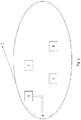
- the portable device (1) in the basic embodiment thereof comprises a housing that internally includes a processing device (2), an air pump (3), a fluidic connection port (4) linked to the air pump (3), an LED emitter (5) and a light detector (6).
- the portable device (1) further comprises a power supply (not shown in Figure 1 ) to power the air pump (3), the fluidic connection port (4), the LED emitter (5) and the light detector (6).
- the power source is a rechargeable battery.
- the processing device (2) controls, at least, the air pump (3), the LED emitter (5) and the power supply and is in data communication with the fluidic connection port (4) and the light detector (6).
- the fluidic connection port (4) is configured to receive an inflatable cuff (8) through which the user can be provided with an output pressure measurement higher than the venous pressure and lower than the systolic pressure of the user.
- the processing device (2) is preferably configured to collect the corresponding measurements of pressure taken through different pressure sensors.
- the LED emitter (5) is configured to emit light with a predetermined wavelength towards a part of the user's body.
- the emitted light can be directed to the user's arm and/or finger.
- the emitted light is infrared.
- the light detector (6) is configured to receive the transmitted or reflected light emitted by the LED emitter (5) on the user's body, determining the intensity value thereof or plethysmographic signal, and to transmit the plethysmographic signal to the data processing device (2).
- the data processing device (2) is configured to receive plethysmographic signals.
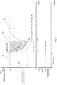
- Figure 2 shows an example of a plethysmographic signal as a function of time (PS(t)) obtained by the processing device (2) during a span of time that includes a period of time (t f ) during which the output pressure measurement has been applied to the user.
- the first area corresponds to the rest region (9) and represents the light intensity values obtained by the light detector (6) before the output pressure measurement is applied.
- the second area corresponds to the transition region (10) and represents the light intensity values obtained by the light detector (6) when the output pressure measurement is being applied.
- the third area corresponds to the recovery region (11) and represents the light intensity values obtained by the light detector (6) after the output pressure measurement is applied and until said values again reach those obtained before the output pressure measurement was applied.
- the light detector (6) is configured to obtain a first plethysmographic signal (PS A (t)) in a first span of time in which at least one first period of time is included during which an output pressure measurement has been applied to the user through the inflatable cuff that is higher than venous pressure and lower than systolic pressure and a second plethysmographic signal (PS B (t)) in a second span of time in which at least one second period of time is included during which an output pressure measurement has been applied to the user that is higher than the venous pressure and lower than the systolic pressure through the inflatable cuff.
- PS A (t) first plethysmographic signal
- PS B (t) plethysmographic signal
- the first period of time and the second period of time have the same temporal duration (t f ).
- the data processing device (2) determines the shift in cardiac output from at least one of the following parameters: slopes of the first and second plethysmographic signals S c A ⁇ S c B ⁇ at the loading point (t 0 , PS 0 ), magnitude of the fall of the first and second plethysmographic signals PS ⁇ f A , PSf ⁇ B in the first time interval, and areas of the regions that lie between the line parallel to the x-axis at a height coinciding with the ordinate of the loading point and the plethysmographic signal Ac ⁇ A Ac ⁇ B in the second time interval; the first interval being within the first and second periods of time and the second interval being within the first and second periods of time.
- the first time interval and the second time interval have the same temporal duration that coincides with the duration of the application of the output pressure measurement (t f ).
- the data processing device (2) is configured to determine the shift in cardiac output from at least one of the following parameters or a combination thereof:
- the plethysmographic signals (PS A (t), PS B (t)) are normalised by the value of each plethysmographic signal at the abscissa of the loading point thereof (specifically, dividing the plethysmographic signal by the corresponding PSo value thereof).
- Figure 3 shows two plethysmographic signals (PS A (t), PS B (t)) normalised to the value of the plethysmographic signal at the abscissa of the loading point, as well as aligned on the x-axis so that the time values of the loading points are visually overlapped, in addition to the graphic representation of each of these parameters (slope, fall and area) for each one, to make them easier to understand.
- the data processing device (2) can determine the shift in output only through the parameter of the slopes of the plethysmographic signals; or only through the values of the fall of the plethysmographic signals; or only through the areas of the designated regions; or through the slopes and falls of the plethysmographic signals; or through the slopes and areas of the regions; or through the falls and areas of the regions; or through the slopes, falls and areas of the regions.
- the data processing device (2) determines the shift in cardiac output, it emits or sends some type of signal (acoustic, visual or of any other type) to the user to inform him or her of such event.
- the data processing device (2) indicates to the user the need to apply the output pressure measurement.
- the data processing device (2) determines that there is a shift in cardiac output if the results across the three parameters (slopes, falls and areas) coincide or if at least the result of the fall and area parameters coincide.
- Figure 4 shows the appearance of a preferred embodiment of the portable device (1), which further includes a flexible cuff (8) configured to take the user's blood pressure.
- the LED emitter (5) and the light detector (6) are integrated into a pulse oximeter (12) through which other parameters such as haemoglobin oxygen saturation can be obtained.
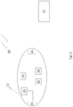
- Figure 5 shows the system (20) for determining a shift in cardiac output according to the invention in the most basic variant thereof.
- the system (20) comprises a portable device (21) and a data processing device (32).
- the portable device (21) comprises processing means (22), an air pump (23), a fluidic connection port (24) linked to the air pump (23), an LED emitter (25), a detector light (26) and a communication port (41).
- the portable device (21) further comprises a power supply (not shown in Figure 5 ) to power the air pump (23), the fluidic connection port (24), the LED emitter (25) and the light detector (26).
- the power source is a rechargeable battery.
- the processing means (22) control, at least, the air pump (23), the LED emitter (25) and the power supply and is in data communication with the fluidic connection port (24) and the light detector (26).
- the fluidic connection port (24) is configured to receive an inflatable cuff (28) through which the user can be provided with an output pressure measurement higher than the venous pressure and lower than the systolic pressure of the user.
- the processing means (22) are preferably configured to collect the corresponding measurements of blood pressure taken through different pressure sensors.
- the LED emitter (25) is configured to emit light with a predetermined wavelength towards a part of the user's body.
- the emitted light can be directed to the user's arm and/or finger.
- the emitted light is infrared.
- the light detector (26) is configured to receive the transmitted or reflected light emitted by the LED emitter (25) on the user's body, determining the intensity value thereof or plethysmographic signal, and to transmit the plethysmographic signal to the data processing means (22).
- the data processing means (22) are configured to receive the plethysmographic signals.
- the light detector (26) is configured to obtain a first plethysmographic signal (PS A (t)) in a first period of time in which a first and second time interval is included during which an output pressure measurement has been applied to the user that is higher than venous pressure and lower than systolic pressure through the inflatable cuff, and a second plethysmographic signal (PS B (t)) in a second period of time in which a first and second time interval is included during which an output pressure measurement has been applied to the user that is higher than venous pressure and lower than systolic pressure through the inflatable cuff.
- PS A (t) a first plethysmographic signal
- PS B (t) plethysmographic signal
- the first period of time and the second period of time have the same temporal duration (t f ).
- the light detector (26) is configured to transmit the plethysmographic signals to the processing means (22).
- the processing means (22) are configured to receive the plethysmographic signals and to transmit them to the communication port (41).
- the communication port (41) is configured to receive the plethysmographic signals and to transmit the plethysmographic signals to the data processing device (32).
- the data processing device (32) is located outside the portable device (21), and can be found on a server, smartphone or any other electronic device.
- the data processing device (32) is configured to receive the plethysmographic signals and to determine the shift in cardiac output from at least one of the following parameters: slopes of the first and second plethysmographic signals ScA ⁇ ScB ⁇ at the loading point (t 0 , PS 0 ), magnitude of the fall of the first and second plethysmographic signals PS ⁇ f A , PSf ⁇ B in a first time interval, and areas of the regions that lie between the line parallel to the x-axis at a height coinciding with the ordinate of the loading point and the plethysmographic signal Ac ⁇ A Ac ⁇ B in a second time interval; the first and second interval being within the first and second periods of time, respectively, during which the output pressure measurement has been applied to the user.
- the first time interval and the second time interval have the same temporal duration that coincides with the duration of the application of the output pressure measurement (t f ).
- the data processing device (32) is configured to determine the shift in cardiac output from at least one of the following parameters or a combination thereof:
- the plethysmographic signals (PS A (t), PS B (t)) are normalised by the value of the plethysmographic signal at the abscissa of the loading point (specifically, by dividing the plethysmographic signal by this value).
- the data processing device (32) can determine the shift in output only through the parameter of the slopes of the plethysmographic signals; or only through the values of the falls of the plethysmographic signals; or only through the areas of the regions; or through the slopes and falls of the plethysmographic signals; or through the slopes and areas of the regions; or through the falls and areas of the regions; or through the slopes, falls and areas of the regions.
- the data processing device (32) determines the shift in cardiac output, it emits or sends some type of signal (acoustic, visual or of any other type) to the user to inform him or her of such event.
- the data processing device (32) indicates to the user the need to repeat the application of the output pressure measurement.
- the data processing device (32) determines that there is a shift in cardiac output if the results across the three parameters (slope, fall and area) coincide or if at least the result of the fall and area parameters coincide.
Landscapes
- Health & Medical Sciences (AREA)
- Life Sciences & Earth Sciences (AREA)
- Engineering & Computer Science (AREA)
- Molecular Biology (AREA)
- Animal Behavior & Ethology (AREA)
- Physiology (AREA)
- Biophysics (AREA)
- Pathology (AREA)
- Veterinary Medicine (AREA)
- Biomedical Technology (AREA)
- Heart & Thoracic Surgery (AREA)
- Medical Informatics (AREA)
- Cardiology (AREA)
- Surgery (AREA)
- Physics & Mathematics (AREA)
- General Health & Medical Sciences (AREA)
- Public Health (AREA)
- Hematology (AREA)
- Artificial Intelligence (AREA)
- Computer Vision & Pattern Recognition (AREA)
- Psychiatry (AREA)
- Signal Processing (AREA)
- Vascular Medicine (AREA)
- Ophthalmology & Optometry (AREA)
- Measuring Pulse, Heart Rate, Blood Pressure Or Blood Flow (AREA)
Applications Claiming Priority (1)
| Application Number | Priority Date | Filing Date | Title |
|---|---|---|---|
| ES202030399A ES2875673B2 (es) | 2020-05-07 | 2020-05-07 | Método, dispositivo y sistema para determinar la tendencia de gasto cardíaco |
Publications (3)
| Publication Number | Publication Date |
|---|---|
| EP3906847A1 true EP3906847A1 (de) | 2021-11-10 |
| EP3906847B1 EP3906847B1 (de) | 2024-11-06 |
| EP3906847C0 EP3906847C0 (de) | 2024-11-06 |
Family
ID=76159407
Family Applications (1)
| Application Number | Title | Priority Date | Filing Date |
|---|---|---|---|
| EP21382412.1A Active EP3906847B1 (de) | 2020-05-07 | 2021-05-07 | Verfahren, vorrichtung und system zur bestimmung einer verschiebung des herzzeitvolumens |
Country Status (2)
| Country | Link |
|---|---|
| EP (1) | EP3906847B1 (de) |
| ES (2) | ES2875673B2 (de) |
Citations (5)
| Publication number | Priority date | Publication date | Assignee | Title |
|---|---|---|---|---|
| EP1173093A1 (de) | 1999-04-27 | 2002-01-23 | Salvatore Romano | Verfahren und gerät zur bestimmung des herzzeitvolumens |
| US6402696B1 (en) * | 2000-04-07 | 2002-06-11 | Ninbar Ltd. | Method for systolic blood pressure measurement |
| US20100191128A1 (en) * | 2008-10-17 | 2010-07-29 | Yale University | Volume Status Monitor: Peripheral Venous Pressure, Hypervolemia and Coherence Analysis |
| ES2587789A1 (es) | 2016-03-31 | 2016-10-26 | Centro Tecnologico Del Mueble Y La Madera De La Region De Murcia | Aparato portátil de medición de la presión arterial y electrocardiograma |
| US20190200879A1 (en) * | 2016-05-20 | 2019-07-04 | Christian Medical College | Non-invasive system and method for measuring blood pressure variability |
Family Cites Families (8)
| Publication number | Priority date | Publication date | Assignee | Title |
|---|---|---|---|---|
| US20070213625A1 (en) * | 2006-02-24 | 2007-09-13 | Larson & Toubro Limited | Cardiac output monitoring system and method using electrical impedance plythesmography |
| US10405762B2 (en) * | 2009-04-22 | 2019-09-10 | Vital Metrix, Inc. | System and method for noninvasively measuring ventricular stroke volume and cardiac output |
| DE102012023275A1 (de) * | 2012-07-12 | 2014-01-16 | Olympus Winter & Ibe Gmbh | Resektoskop |
| US20180206789A1 (en) * | 2017-01-24 | 2018-07-26 | Edwards Lifesciences Corporation | Extremity cuff such as a finger cuff, a method and a computer program product |
| CN107296593A (zh) * | 2017-05-31 | 2017-10-27 | 江苏斯坦德利医疗科技有限公司 | 一种血液动力学参数获取方法及装置 |
| WO2019071198A1 (en) * | 2017-10-06 | 2019-04-11 | The Regents Of The University Of California | METHODS FOR MONITORING HEMODYNAMICALLY SIGNIFICANT HEART RATE DISORDERS AND DEVICES FOR IMPLEMENTING THE SAME |
| US20190167195A1 (en) * | 2017-12-04 | 2019-06-06 | Edwards Lifesciences Corporation | Systems and methods for performing diagnostic procedures for a volume clamp finger cuff |
| US11766198B2 (en) * | 2018-02-02 | 2023-09-26 | Cercacor Laboratories, Inc. | Limb-worn patient monitoring device |
-
2020
- 2020-05-07 ES ES202030399A patent/ES2875673B2/es active Active
-
2021
- 2021-05-07 EP EP21382412.1A patent/EP3906847B1/de active Active
- 2021-05-07 ES ES21382412T patent/ES2999692T3/es active Active
Patent Citations (5)
| Publication number | Priority date | Publication date | Assignee | Title |
|---|---|---|---|---|
| EP1173093A1 (de) | 1999-04-27 | 2002-01-23 | Salvatore Romano | Verfahren und gerät zur bestimmung des herzzeitvolumens |
| US6402696B1 (en) * | 2000-04-07 | 2002-06-11 | Ninbar Ltd. | Method for systolic blood pressure measurement |
| US20100191128A1 (en) * | 2008-10-17 | 2010-07-29 | Yale University | Volume Status Monitor: Peripheral Venous Pressure, Hypervolemia and Coherence Analysis |
| ES2587789A1 (es) | 2016-03-31 | 2016-10-26 | Centro Tecnologico Del Mueble Y La Madera De La Region De Murcia | Aparato portátil de medición de la presión arterial y electrocardiograma |
| US20190200879A1 (en) * | 2016-05-20 | 2019-07-04 | Christian Medical College | Non-invasive system and method for measuring blood pressure variability |
Also Published As
| Publication number | Publication date |
|---|---|
| ES2875673A1 (es) | 2021-11-10 |
| EP3906847B1 (de) | 2024-11-06 |
| ES2875673B2 (es) | 2022-04-29 |
| ES2999692T3 (en) | 2025-02-26 |
| EP3906847C0 (de) | 2024-11-06 |
Similar Documents
| Publication | Publication Date | Title |
|---|---|---|
| EP3781029B1 (de) | Vorrichtung, system und verfahren zur unterstützung der detektion der rückkehr von spontaner zirkulation während kardiopulmonaler wiederbelebung | |
| US8834378B2 (en) | Systems and methods for determining respiratory effort | |
| JP5748160B2 (ja) | 携帯診断装置 | |
| US11058303B2 (en) | System and method for determining stability of cardiac output | |
| EP2289405B1 (de) | Biologischer Informationsmonitor | |
| WO2015042484A1 (en) | Hydration monitoring | |
| EP2727524A1 (de) | Verfahren und Vorrichtung zum Messen der Blutmenge | |
| US20120150003A1 (en) | System Non-invasive Cardiac Output Determination | |
| US20120259190A1 (en) | Detection of oximetry sensor sites based on waveform characteristics | |
| US20030032887A1 (en) | Heartbeat synchronous information acquiring apparatus and pulse wave propagation velocity related information acquiring apparatus, blood pressure monitoring apparatus and preejection period measuring apparatus utilizing heartbeat synchronous information | |
| KR102560306B1 (ko) | 혈압 추정 장치 및 방법 | |
| US20200196878A1 (en) | System and method for blood pressure monitoring with subject awareness information | |
| KR100610813B1 (ko) | 혈압 측정 회로가 내장된 배터리 팩과 결합 가능한 이동통신 단말기 | |
| US7678057B2 (en) | Device and system that identifies cardiovascular insufficiency | |
| KR20210114228A (ko) | 생체정보 추정 장치 및 방법 | |
| JP4433756B2 (ja) | 生体情報計測装置及びその制御方法、制御プログラム及び記録媒体 | |
| JP5077326B2 (ja) | 生体情報計測装置及びその制御方法、制御プログラム | |
| US20210113097A1 (en) | Heart failure degree-of-exacerbation determination system and heart failure degree-of-exacerbation determination method | |
| US6878273B2 (en) | Dialyzing apparatus | |
| EP3906847B1 (de) | Verfahren, vorrichtung und system zur bestimmung einer verschiebung des herzzeitvolumens | |
| US11020010B2 (en) | Blood pressure/pulse wave measurement device | |
| US20230240602A1 (en) | Inducing hypoxia to monitor one or more patient conditions using a medical device system | |
| EP4088653A1 (de) | Pulswellenanalysevorrichtung, pulswellenanalyseverfahren und pulswellenanalyseprogramm | |
| CN120360510B (zh) | 缺血预适应机制驱动的智能训练方法及训练仪 | |
| KR102553033B1 (ko) | 혈압 추정을 위한 특징 획득 방법, 혈압 추정 장치 및 방법 |
Legal Events
| Date | Code | Title | Description |
|---|---|---|---|
| PUAI | Public reference made under article 153(3) epc to a published international application that has entered the european phase |
Free format text: ORIGINAL CODE: 0009012 |
|
| STAA | Information on the status of an ep patent application or granted ep patent |
Free format text: STATUS: THE APPLICATION HAS BEEN PUBLISHED |
|
| AK | Designated contracting states |
Kind code of ref document: A1 Designated state(s): AL AT BE BG CH CY CZ DE DK EE ES FI FR GB GR HR HU IE IS IT LI LT LU LV MC MK MT NL NO PL PT RO RS SE SI SK SM TR |
|
| B565 | Issuance of search results under rule 164(2) epc |
Effective date: 20210922 |
|
| STAA | Information on the status of an ep patent application or granted ep patent |
Free format text: STATUS: REQUEST FOR EXAMINATION WAS MADE |
|
| 17P | Request for examination filed |
Effective date: 20220509 |
|
| RBV | Designated contracting states (corrected) |
Designated state(s): AL AT BE BG CH CY CZ DE DK EE ES FI FR GB GR HR HU IE IS IT LI LT LU LV MC MK MT NL NO PL PT RO RS SE SI SK SM TR |
|
| GRAP | Despatch of communication of intention to grant a patent |
Free format text: ORIGINAL CODE: EPIDOSNIGR1 |
|
| STAA | Information on the status of an ep patent application or granted ep patent |
Free format text: STATUS: GRANT OF PATENT IS INTENDED |
|
| RIC1 | Information provided on ipc code assigned before grant |
Ipc: A61B 5/0295 20060101ALI20240426BHEP Ipc: A61B 5/00 20060101ALI20240426BHEP Ipc: A61B 5/026 20060101ALI20240426BHEP Ipc: A61B 5/022 20060101AFI20240426BHEP |
|
| INTG | Intention to grant announced |
Effective date: 20240531 |
|
| RIN1 | Information on inventor provided before grant (corrected) |
Inventor name: BETETA MUNOZ, MIGUEL ANGEL Inventor name: LOPEZ GARCIA, PEDRO CARLOS Inventor name: VIDAL POVEDA, JOSE ARTURO Inventor name: RUIZ NOLASCO, RICARDO Inventor name: GARCIA ALBEROLA, ARCADIO Inventor name: CORRAL HERRANZ, JAVIER Inventor name: LOPEZ ESPINOSA, OVIDIO Inventor name: BLEDA TOMAS, ANDRES LORENZO Inventor name: MAESTRE FERRIZ, RAFAEL |
|
| GRAS | Grant fee paid |
Free format text: ORIGINAL CODE: EPIDOSNIGR3 |
|
| GRAA | (expected) grant |
Free format text: ORIGINAL CODE: 0009210 |
|
| STAA | Information on the status of an ep patent application or granted ep patent |
Free format text: STATUS: THE PATENT HAS BEEN GRANTED |
|
| AK | Designated contracting states |
Kind code of ref document: B1 Designated state(s): AL AT BE BG CH CY CZ DE DK EE ES FI FR GB GR HR HU IE IS IT LI LT LU LV MC MK MT NL NO PL PT RO RS SE SI SK SM TR |
|
| REG | Reference to a national code |
Ref country code: GB Ref legal event code: FG4D |
|
| REG | Reference to a national code |
Ref country code: CH Ref legal event code: EP |
|
| REG | Reference to a national code |
Ref country code: DE Ref legal event code: R096 Ref document number: 602021021363 Country of ref document: DE |
|
| REG | Reference to a national code |
Ref country code: IE Ref legal event code: FG4D |
|
| U01 | Request for unitary effect filed |
Effective date: 20241204 |
|
| U07 | Unitary effect registered |
Designated state(s): AT BE BG DE DK EE FI FR IT LT LU LV MT NL PT RO SE SI Effective date: 20241213 |
|
| REG | Reference to a national code |
Ref country code: ES Ref legal event code: FG2A Ref document number: 2999692 Country of ref document: ES Kind code of ref document: T3 Effective date: 20250226 |
|
| PG25 | Lapsed in a contracting state [announced via postgrant information from national office to epo] |
Ref country code: HR Free format text: LAPSE BECAUSE OF FAILURE TO SUBMIT A TRANSLATION OF THE DESCRIPTION OR TO PAY THE FEE WITHIN THE PRESCRIBED TIME-LIMIT Effective date: 20241106 Ref country code: IS Free format text: LAPSE BECAUSE OF FAILURE TO SUBMIT A TRANSLATION OF THE DESCRIPTION OR TO PAY THE FEE WITHIN THE PRESCRIBED TIME-LIMIT Effective date: 20250306 |
|
| PG25 | Lapsed in a contracting state [announced via postgrant information from national office to epo] |
Ref country code: NO Free format text: LAPSE BECAUSE OF FAILURE TO SUBMIT A TRANSLATION OF THE DESCRIPTION OR TO PAY THE FEE WITHIN THE PRESCRIBED TIME-LIMIT Effective date: 20250206 |
|
| PG25 | Lapsed in a contracting state [announced via postgrant information from national office to epo] |
Ref country code: GR Free format text: LAPSE BECAUSE OF FAILURE TO SUBMIT A TRANSLATION OF THE DESCRIPTION OR TO PAY THE FEE WITHIN THE PRESCRIBED TIME-LIMIT Effective date: 20250207 |
|
| PG25 | Lapsed in a contracting state [announced via postgrant information from national office to epo] |
Ref country code: PL Free format text: LAPSE BECAUSE OF FAILURE TO SUBMIT A TRANSLATION OF THE DESCRIPTION OR TO PAY THE FEE WITHIN THE PRESCRIBED TIME-LIMIT Effective date: 20241106 |
|
| PG25 | Lapsed in a contracting state [announced via postgrant information from national office to epo] |
Ref country code: RS Free format text: LAPSE BECAUSE OF FAILURE TO SUBMIT A TRANSLATION OF THE DESCRIPTION OR TO PAY THE FEE WITHIN THE PRESCRIBED TIME-LIMIT Effective date: 20250206 |
|
| U20 | Renewal fee for the european patent with unitary effect paid |
Year of fee payment: 5 Effective date: 20250519 |
|
| PG25 | Lapsed in a contracting state [announced via postgrant information from national office to epo] |
Ref country code: SM Free format text: LAPSE BECAUSE OF FAILURE TO SUBMIT A TRANSLATION OF THE DESCRIPTION OR TO PAY THE FEE WITHIN THE PRESCRIBED TIME-LIMIT Effective date: 20241106 |
|
| PG25 | Lapsed in a contracting state [announced via postgrant information from national office to epo] |
Ref country code: SK Free format text: LAPSE BECAUSE OF FAILURE TO SUBMIT A TRANSLATION OF THE DESCRIPTION OR TO PAY THE FEE WITHIN THE PRESCRIBED TIME-LIMIT Effective date: 20241106 |
|
| PG25 | Lapsed in a contracting state [announced via postgrant information from national office to epo] |
Ref country code: CZ Free format text: LAPSE BECAUSE OF FAILURE TO SUBMIT A TRANSLATION OF THE DESCRIPTION OR TO PAY THE FEE WITHIN THE PRESCRIBED TIME-LIMIT Effective date: 20241106 |
|
| PLBE | No opposition filed within time limit |
Free format text: ORIGINAL CODE: 0009261 |
|
| STAA | Information on the status of an ep patent application or granted ep patent |
Free format text: STATUS: NO OPPOSITION FILED WITHIN TIME LIMIT |
|
| PGFP | Annual fee paid to national office [announced via postgrant information from national office to epo] |
Ref country code: ES Payment date: 20250721 Year of fee payment: 5 |
|
| 26N | No opposition filed |
Effective date: 20250807 |
|
| REG | Reference to a national code |
Ref country code: CH Ref legal event code: H13 Free format text: ST27 STATUS EVENT CODE: U-0-0-H10-H13 (AS PROVIDED BY THE NATIONAL OFFICE) Effective date: 20251223 |
|
| PG25 | Lapsed in a contracting state [announced via postgrant information from national office to epo] |
Ref country code: CH Free format text: LAPSE BECAUSE OF NON-PAYMENT OF DUE FEES Effective date: 20250531 |
|
| GBPC | Gb: european patent ceased through non-payment of renewal fee |
Effective date: 20250507 |
|
| PG25 | Lapsed in a contracting state [announced via postgrant information from national office to epo] |
Ref country code: MC Free format text: LAPSE BECAUSE OF FAILURE TO SUBMIT A TRANSLATION OF THE DESCRIPTION OR TO PAY THE FEE WITHIN THE PRESCRIBED TIME-LIMIT Effective date: 20241106 |
|
| PG25 | Lapsed in a contracting state [announced via postgrant information from national office to epo] |
Ref country code: GB Free format text: LAPSE BECAUSE OF NON-PAYMENT OF DUE FEES Effective date: 20250507 |
|
| PG25 | Lapsed in a contracting state [announced via postgrant information from national office to epo] |
Ref country code: IE Free format text: LAPSE BECAUSE OF NON-PAYMENT OF DUE FEES Effective date: 20250507 |