EP3906976A2 - Dispositif de protection contre les incendies - Google Patents
Dispositif de protection contre les incendies Download PDFInfo
- Publication number
- EP3906976A2 EP3906976A2 EP20217871.1A EP20217871A EP3906976A2 EP 3906976 A2 EP3906976 A2 EP 3906976A2 EP 20217871 A EP20217871 A EP 20217871A EP 3906976 A2 EP3906976 A2 EP 3906976A2
- Authority
- EP
- European Patent Office
- Prior art keywords
- sensor
- extinguishing
- protection device
- fire protection
- fire
- Prior art date
- Legal status (The legal status is an assumption and is not a legal conclusion. Google has not performed a legal analysis and makes no representation as to the accuracy of the status listed.)
- Withdrawn
Links
Images


Classifications
-
- A—HUMAN NECESSITIES
- A62—LIFE-SAVING; FIRE-FIGHTING
- A62C—FIRE-FIGHTING
- A62C35/00—Permanently-installed equipment
- A62C35/02—Permanently-installed equipment with containers for delivering the extinguishing substance
- A62C35/10—Containers destroyed or opened by flames or heat
-
- A—HUMAN NECESSITIES
- A62—LIFE-SAVING; FIRE-FIGHTING
- A62C—FIRE-FIGHTING
- A62C37/00—Control of fire-fighting equipment
- A62C37/08—Control of fire-fighting equipment comprising an outlet device containing a sensor, or itself being the sensor, i.e. self-contained sprinklers
- A62C37/10—Releasing means, e.g. electrically released
- A62C37/11—Releasing means, e.g. electrically released heat-sensitive
- A62C37/14—Releasing means, e.g. electrically released heat-sensitive with frangible vessels
-
- A—HUMAN NECESSITIES
- A62—LIFE-SAVING; FIRE-FIGHTING
- A62C—FIRE-FIGHTING
- A62C37/00—Control of fire-fighting equipment
- A62C37/36—Control of fire-fighting equipment an actuating signal being generated by a sensor separate from an outlet device
- A62C37/38—Control of fire-fighting equipment an actuating signal being generated by a sensor separate from an outlet device by both sensor and actuator, e.g. valve, being in the danger zone
- A62C37/40—Control of fire-fighting equipment an actuating signal being generated by a sensor separate from an outlet device by both sensor and actuator, e.g. valve, being in the danger zone with electric connection between sensor and actuator
Definitions
- the present invention relates to a fire protection device for protecting at least one room, comprising a detection device for detecting one or more fire parameters, and an extinguishing device, which is provided for delivering an extinguishing agent into each protected room, wherein the detection device is designed to activate the extinguishing device in a room on detection of at least one fire parameter.
- 'a fire protection device' means a device by which the development of a fire in a room can be prevented or delayed or by which a fire can be extinguished or by which the propagation of a fire can be prevented or delayed.
- 'fire' refers not only to literal burning, in the presence of a flame, but also to smouldering or glowing without a flame.
- 'a fire parameter' means a parameter that is associated with the presence of a fire or an incipient fire or with the development of a fire, e.g. in the case of smouldering or melting of an object or if an apparatus or a machine is in an overheated state.
- a fire parameter of this type is for example a certain temperature rise of the ambient air within a certain period of time or the presence in the air, or presence above a certain threshold concentration in the air, of a particular gas or of a combination of two or more gases or the presence of smoke.
- the detection device may also be arranged in such a way that it only activates the extinguishing device when two or more fire parameters are detected together.
- the term 'room' means both a room enclosed by walls and a completely or partially open space. This term may also be used in the sense of a zone that is not delimited. In a number of fields of application, the room will be located within a building, for example such as a kitchen, a bedroom or a living room of a dwelling, an office room, a shop room, a stockroom, a storage room, a hotel room, a room for student accommodation, a garage, a machine room, a lift shaft, a car park, a workplace, a stable, but in other possible fields of application the room may also be located in a temporary structure, for example such as a marquee, or in a space of a means of transport, for example such as a loading space of a lorry or a train or the space inside a caravan or a boat. This is not an exhaustive list.
- extinguishing agent means any existing solid, liquid or gaseous extinguishing agent, for example such as a gas or a gas mixture with extinguishing properties or an extinguishing powder or an extinguishing foam or water that has been treated and/or to which one or more additives have been added in order to improve its extinguishing properties or to increase safety during extinguishing.
- a sprinkler system that comprises several sprinkler heads, which are connected to a common mains system.
- This mains system is connected to a supply pipe, via which extinguishing agent is supplied, for example a water mains, or to a storage tank in which a supply of extinguishing agent is provided.
- Each sprinkler head protects a respective room.
- a sprinkler head is activated when a predetermined threshold temperature is reached.
- most sprinkler heads are provided with a closed glass bulb that closes the nozzle.
- the glass bulb also called a glass tube, contains a liquid which when heated expands so that the glass tube breaks and the extinguishing agent is sprayed into the room via the sprinkler head.
- the threshold temperature is often set at 30°C above the normal temperature in the room.
- the mains system of the known sprinkler systems must extend from the supply pipe or the storage tank into the various rooms to be protected and so is often quite extensive. If the rooms to be protected are far apart, the mains system must also in each case bridge the distance between them and extend over a considerable distance. In addition, the extensive mains system must constantly remain under pressure, so that it is susceptible to leaks. Another drawback is that damage or defects on the mains system may have the consequence that there is no longer a supply of extinguishing agent to a number of sprinkler heads.
- the aim of the present invention is to rectify the aforementioned drawbacks.
- an extinguishing unit which comprises a reservoir in which a quantity of extinguishing agent is provided, and which is arranged to deliver extinguishing agent from the reservoir into said room, on detection of at least one fire parameter.
- the fire protection device protects two or more rooms, and an extinguishing unit of this kind is provided in each room.
- extinguishing agent may be sprayed preventively in other rooms of the same building, for example in the rooms that are located next to or above or under the room where detection of a fire occurred. Possible spread of the fire is stopped or at least delayed thereby.
- a separate fire protection device operating autonomously, with its own supply of extinguishing agent, is thus placed in each room to be protected against fire. It is therefore no longer necessary to provide an extensive pipe system that is permanently under pressure and that connects all rooms that are to be protected against fire to one another.
- each extinguishing unit comprises an extinguishing head connected to the reservoir with an opening via which the extinguishing agent can be delivered from the reservoir into the protected room.
- the extinguishing head may for example be a known sprinkler head.
- the reservoir need not necessarily be connected to a supply pipe or another reservoir, but this is nevertheless included in the possibilities for supplying extinguishing agent to the extinguishing unit.
- the extinguishing agent is provided under pressure in the reservoir, for example at a pressure of 6 bar.
- the reservoir preferably has a cubic capacity of 1 litre or 2 litres or 4 litres or 6 litres or 9 litres.
- the extinguishing agent On activation of the extinguishing device, the extinguishing agent is for example allowed to spray out of the reservoir via a spraying element that operates and/or is formed in such a way that the extinguishing agent is distributed into the environment around it.
- the spraying element is preferably adjusted in such a way that the extinguishing agent is distributed over the whole room to be protected.
- the extinguishing properties of the extinguishing agent itself and/or the amount of extinguishing agent that is distributed in the room (determined by, among other things, the size of the reservoir) and/or the length of time during which the extinguishing agent is distributed, are preferably defined so that the extinguishing effect of the whole extinguishing activity is adapted to the flammability of the products or objects present in the room.
- the extinguishing properties of the extinguishing agent and/or the amount of extinguishing agent and/or the extinguishing time may for example (also) be adapted to the accessibility of the protected room for the execution of extinguishing activities by a person summoned for this.
- the estimated time interval between informing the fire brigade and the start of extinguishing activities by the fire brigade is for example taken into account.
- the extinguishing effect of the whole extinguishing activity coincides with the extinguishing effect of extinguishing for at least 60 minutes with ordinary water from a conventional sprinkler head.
- the extinguishing effect may be allowed to coincide with a shorter (e.g. at least 30 minutes or at least 45 minutes) or a longer duration (e.g. at least 75 minutes or at least 90 minutes) of extinguishing with ordinary water from a conventional sprinkler head.
- the present invention also relates to an extinguishing unit for protecting a room against fire, comprising a reservoir that is provided for providing a quantity of extinguishing agent, an extinguishing head connected to the reservoir with a discharge orifice for delivering extinguishing agent from the reservoir into the protected room, and a detection and activation device that is arranged to open the discharge orifice of the extinguishing head on detection of one or more fire parameters.
- the present invention also relates to a set of extinguishing units for protecting a number of rooms against fire, with the properties indicated in the preceding paragraph. Each extinguishing unit is then provided to be placed in a respective room and thus create a fire protection device with the properties stated above.
- an extinguishing agent e.g. water, to which an additive is added that comprises a plant extract and/or a mineral salt of an acid.
- An extinguishing agent of this kind is preferably provided in the reservoir of an extinguishing unit according to the present invention described above.
- the extinguishing agent may however also be used for extinguishing without making use of an extinguishing unit of this kind.
- the extinguishing agent may moreover be delivered into a room in any way.
- the additive is preferably an extinguishing foam, such as an ecological telomer-based foam, preferably without persistent, bio-accumulative and toxic constituents, or a fluorine-free foam or a foam of class A.
- Said foam of class A is a mixture of water, air and a wetting agent and was specially developed for combating forest fires and extinguishing burning waste etc.
- the following extinguishing agents are used (the percentages stated hereunder are ratios of the volume of the additive to the volume of water):
- the mixing ratios are adjusted and/or extra additives are added, depending on the precise circumstances.
- the liquid extinguishing agent is for example water that has undergone a treatment, for example a treatment at the nanoscale, so that it has a reduced conductivity or is non-conductive.
- the extinguishing agent preferably comprises a wetting agent and/or a surfactant.
- Each additive is preferably added at a mixing ratio relative to the extinguishing agent from 1.5% to 15%.
- the additive is for example very suitable in itself for extinguishing burning substances of classes A (wood, paper, etc.), B (oil, petrol, etc.), and F (fats, frying oil, etc.).
- the present invention also relates to any type of fire protection device, in particular a fire protection device according to the first, third, fourth or fifth aspect of the present invention, in which an extinguishing agent according to the present invention is provided.
- an actuator for activating an extinguishing device or a fire alarm device that comprises a breakable detection element or a breakable activation element.
- This breakable part is for example a closed container in which a liquid or a gas is provided.
- the breakable part is preferably made of glass.
- fire detection devices that are provided with a breakable element that breaks at a predetermined rupture temperature and activates an extinguishing device thereby.
- the breakable element is for example in the form of a glass bulb. This is the case in known sprinkler systems.
- Each sprinkler head is provided with a glass tube that is designed to break on exceeding a certain temperature limit, typically 68°C, so that the nozzle of the sprinkler head in question is opened and extinguishing agent is sprayed into the protected room or zone.
- the aim of the present invention is to rectify this drawback.
- this aim is achieved by providing an actuator that is designed to be installed in the vicinity of a breakable detection element or a breakable activation element, and which comprises a breaking device in order to break said breakable part, wherein the actuator is activatable by means of a signal that is generated by another detection device.
- An actuator of this kind with the characteristic features that are described in the preceding paragraph and hereunder and are presented in the claims, may be incorporated in a fire protection device with the features described above relating to the first aspect of the present invention, but may also be used in any other type of fire protection device to activate an extinguishing device or an alarm device with a breakable detection element or a breakable activation element by means of another activation means or detecting means.
- the present invention thus also relates to any fire protection device, in particular a fire protection device with the features according to the first aspect of the present invention, which comprises a breakable activation or detection element for activating an alarm device or an extinguishing device, and an actuator that is designed to break the breakable activation or detection element, wherein the actuator is activatable by another activation means or detecting means.
- the present invention provides an actuator that is designed to break the glass tube as a result of detection of at least one fire parameter by said other detection element.
- This other detection element is for example a detection element for detecting the presence of smoke or of a gas.
- the actuator may be set up in such a way that this sheet-form element breaks as a result of detection of at least one fire parameter, by any detection element.
- the actuator may comprise a breaking device that comprises a movable breaking means for breaking the breakable activation or detection element by contact with the breaking means, for example such as by striking it.
- the breaking device may also be provided with heating means for heating the breakable activation or detection element until it breaks, in other words by heating until it reaches the rupture temperature, wherein the heat required for this is obtained for example by burning a gas or by means of an electric current.
- the breaking device may also be designed to create a gas stream or liquid stream directed onto the breakable activation or detection element in order to break it, wherein the breakable element is for example broken by the pressure that is exerted by said gas or liquid stream on that element.
- the actuator is a module that is fastened on or against a breakable activation element or detection element of a sprinkler head of a sprinkler installation and is designed to break the breakable element thereof.
- An example of an actuator with a mechanically acting breaking device comprises a motor that is designed to move a needle or a pin by means of a drive mechanism so that the needle or the pin pushes against or strikes the glass tube and breaks the glass tube.
- An actuator with a thermally acting breaking device comprises for example an electric heating element that heats a metal plate in the vicinity of a sprinkler head. As a result, the glass tube of the sprinkler head is heated until it reaches the rupture temperature. In an alternative embodiment, a flame is generated and is directed onto the sprinkler head, with the same effect.
- the breaking device comprises a reservoir, in which a gas or a liquid is stored at high pressure, which is installed in the vicinity of the sprinkler head.
- a reservoir in which a gas or a liquid is stored at high pressure, which is installed in the vicinity of the sprinkler head.
- An actuator consists for example of three components, namely a communication module, a breaking device and a battery. These components are connected together and interact.
- the communication module may operate at various frequencies, preferably in the standard band 868 MHz or 433 MHz.
- the battery is replaceable and may have various capacities.
- the breaking device comprises for example a motor that drives a gear system.
- the gear system is designed to move a pin along its longitudinal direction, so that it strikes the glass tube at high speed and causes it to break. It is possible to select a gear system with two interacting gears that are located on both sides of the pin or on either side of a pin holder, and engage on this pin or this pin holder. It is also possible to select just one gear, which engages on the pin or pin holder.
- engaging means are provided on the pin or on the pin holder, for example such as teeth that are designed to interact with the at least one gear of the gear system.
- the pin By driving the single gear or at least one of the two gears, wherein these two gears turn in an opposite sense of rotation, the pin can be moved in the direction of the glass tube. It is possible to select driving of both gears by means of a respective motor or driving of only one of the two gears. Driving of both gears offers greater operational reliability.
- the breaking device comprises a heat source, the heat of which is obtained electrically.
- the breaking device comprises a heat source whose heat is obtained by burning a gas.
- the heat required Q must be divided by the energy P with which the object is heated to obtain the required heating time t. It is obvious that this heating time can also be determined experimentally.
- an electric heating element is placed against the glass tube.
- an electric current is passed through the heating element, so that it heats up very quickly and the glass tube quickly reaches the rupture temperature.
- the breaking device comprises a reservoir in which butane, propane or some other flammable gas is stored under a pressure of at least 10 bar, preferably not more than 20 bar.
- This reservoir has a discharge orifice which is closed with a shut-off valve that is operable by means of an electromagnet (an electromagnetically operable shut-off valve is also called a solenoid valve hereinafter) wherein the discharge orifice is located in the vicinity of the glass tube.
- An ignition element is provided in the vicinity of the discharge orifice, with which a spark can be formed by means of an electric current.
- Activation of the actuator firstly involves the discharge orifice of the reservoir being opened by operation of the solenoid valve, and immediately thereafter, after a time interval that roughly coincides with the time the gas takes to reach the discharge orifice, a voltage is applied between two conductors of the ignition element so that a spark is generated, which causes the gas to ignite. For a certain period, in this way a spark is formed repeatedly in the ignition element with a time interval as short as possible to guarantee ignition of the gas.
- the amount of gas in the reservoir is sufficient to bring the glass tube located next to the discharge orifice, by means of the burning gas, to a temperature that is equal to or higher than the rupture temperature.
- a mixture of gas and oxygen is provided, with a mixing ratio such that the gas burns immediately and intensely and quickly reaches its maximum temperature. Generally this is a temperature above 1000°C, thus ensuring that the glass tube will break quickly.
- the gas might also not be mixed with oxygen beforehand, so that less complete combustion takes place. With this combustion, however, a temperature of 500°C is still easily reached.
- Reclosing of the discharge orifice can also be controlled by means of a signal received from a sensor, for example from a sensor, e.g. a water sensor, that detects whether the extinguishing device is operating and closes the discharge orifice of the reservoir after the presence of water or another extinguishing agent has been detected.
- a sensor e.g. a water sensor
- the breaking device of the actuator comprises a reservoir with a gas or a liquid under high pressure with a discharge orifice that can be opened or closed by means of a shut-off valve.
- the shut-off valve may be operated by means of an electromagnet.
- a current is passed through the electromagnet so that the shut-off valve is brought very quickly to an open position. This takes place so quickly that a powerful gas stream leaves the reservoir via the discharge orifice. This powerful gas stream is directed onto the glass tube, so that a pressure is exerted on this glass tube that is sufficient to break the glass tube.
- a modular sensor is provided.
- the monitoring of parameters in the human living and work environment is known. This may for example involve parameters relating to air quality such as temperature, humidity, CO content or the presence of gases that may be injurious to health, or parameters relating to fire safety, e.g. the aforementioned fire parameters or parameters relating to protection against burglary or theft, for example movement, or the breaking of glass. Other parameters, for example such as the open or closed state of a window or door or the energy consumption in a particular room or in a particular building may be monitored.
- multifunctional detection units tailor-made for the user, which comprise a number of detectors or sensors with a respective function, and associated components and a suitable housing. These detection units are developed in each case for a well-defined combination of sensor functions, and this is time-consuming and expensive.
- the present invention provides a modular sensor, comprising a sensor base and at least two sensor modules that are suitable for detecting respective mutually different parameters, wherein each sensor module can be connected to the sensor base to form a sensor unit, optionally with the desired sensor function(s).
- module is used in this patent application in the meaning of a number of available sensor components, from which a sensor with the desired sensor functions can be assembled.
- a fire protection device which comprises a sensor unit of modular assembly, assembled by selecting one or more desired sensor modules from a number of sensor modules that are offered or are available.
- This fire protection device may be any fire protection device, but is in particular the fire protection device that is described above with reference to the first and the third aspect of the present invention.
- sensors or two sensor modules that are designed to detect a mutually different parameter are also indicated in this patent application as sensors or sensor modules with a different sensor function.
- this fire protection device comprises a sensor unit that is assembled from a set of sensor components comprising a sensor base with at least one sensor position for placement of a sensor module, and at least two sensor modules that are suitable for detecting respective mutually different parameters, wherein each sensor module can be connected to the sensor base to form a sensor unit, optionally with the desired sensor function(s).
- a user may himself assemble or modify a sensor unit in order to monitor the desired parameter or parameter set.
- users are offered a 'drag and drop' modularity, wherein they themselves can assemble a sensor unit with the desired parametric function(s).
- a sensor unit may be assembled that monitors the air humidity and the CO 2 concentration of the ambient air.
- the user may also assemble a sensor unit that detects both movement and the exceeding of a threshold concentration of CO in a particular room. If desired, the user may also add for example detection of a certain temperature being exceeded, or detection that smoke is present in the room that is being monitored.
- a sensor unit may be assembled that has each possible sensor function or monitors each possible combination of two or more parameters.
- the developer and manufacturer has the advantage that developments and adjustments take less time.
- it is also easy to replace a faulty sensor module, so that repairs and maintenance proceed more easily.
- At least one sensor position is provided on the sensor base.
- at least two sensor positions are provided, preferably two, three or four sensor positions.
- At each sensor position an identical first connector is provided, whereas each sensor module comprises a second connector that is designed to interact with said first connector at each sensor position of the sensor base.
- the modular sensor according to the present invention preferably comprises at least two different sensor bases, which have a different number of sensor positions respectively.
- Each sensor base of the modular sensor according to the present invention preferably comprises a printed circuit board (PCB) provided with a first connecting means for connecting to a power source and a second connecting means for connecting to a data communication means.
- PCB printed circuit board
- Data communication takes place for example via an I 2 C bus, a synchronous, serial bus developed for data communication between microprocessors and other ICs.
- the modular sensor according to the present invention preferably also comprises at least two different housings, which are adapted to different sensor functions.
- a first housing may be provided with mainly closed walls that enclose the components, and/or a second housing, at least one wall of which is perforated for assembling a sensor unit, for which at least one of the sensor modules fitted on the sensor base is designed to monitor a parameter of the ambient air, for example the presence of a particular gas, and/or a third housing with at least one wall in which an opening is provided in which a lens is placed for assembling a sensor unit, for which at least one of the sensor modules fitted on the sensor base comprises a light sensor.
- the modular sensor according to the present invention preferably also comprises at least two different battery modules with a mutually different power and/or different capacity.
- the user may also select the battery that has, among other things depending on the selected sensor modules, the frequency with which the software checks whether new data are available ('polling rate') and the type of antenna, the desired discharge time and/or the desired life.
- Each sensor module is preferably provided on a printed circuit board with smaller dimensions than the printed circuit board of the sensor base and comprises a second connector that is complementary to the first connector on the printed circuit board of the sensor base.
- Each sensor module has dimensions such that it fits within the free space that is provided at each sensor position.
- the selected sensor module is coupled to the sensor base by coupling the first connector to the sensor base and the second connector to the sensor module.
- the coupling between these first and second connectors may for example be provided by means of a simple click connection.
- each sensor has a unique address
- the data processing means that interact with a sensor unit recognize which type of sensor is located at each sensor position of the sensor base, and the data received therefrom can be processed and interpreted correctly. This by for example making use of a protocol, such as I 2 C with '10-bit addressing', so that just under 1023 addresses are available for identifying the various sensors.
- a detector is provided that is designed to detect the presence of one or more harmful substances in the air.
- a fire protection device which comprises a detector that is designed to detect the presence of one or more harmful substances in the air.
- This fire protection device may be any fire protection device, but is in particular the fire protection device that is described above with reference to the first, third or fourth aspect of the present invention.
- the fire protection device in particular the detector itself, is designed to evaluate the harmfulness of the substances present in the air.
- air' is used here in the sense of the air (as a gas mixture) that is present in the environment of the detector.
- the substances present in the air are all substances that are mixed with said air or are taken up therein, regardless of their state. Thus, these substances may be present in the air in the form of gases or vapours or as constituents of smoke or in the form of a mist or as airborne solid particles.
- Determination of the harmfulness of the substances present in the air is for example based on the nature of the substances detected, whether or not in combination with a parameter relating to the concentration of the detected material in the air.
- a possible parameter with regard to the concentration of a detected material is the indication whether or not a certain threshold concentration of the material in the air is exceeded.
- Based on the nature of the substances detected optionally also taking into account a parameter relating to their concentration or their measured or established concentration, for example two or more degrees of harmfulness may be determined.
- the detector according to the invention is for example designed to detect whether the air contains one or more predetermined harmful gases, and to evaluate the harmfulness of the smoke on the basis of this information. This evaluation checks for example whether the smoke is harmful and for example has been produced by a fire, or is less harmful and for example has come from a cigarette, or is harmless and for example is produced by a smoke machine.
- This information supplied by the fire protection device concerning the harmfulness of the substances present in the air can be used for deciding, according to a previously established decision criterion, whether or not action must be taken, and if so, what action.
- class A very harmful
- class B harmful
- class C harmless
- the fire brigade must be informed immediately
- the fire protection device is for example designed to use the evaluation of the harmfulness of the substances present in the air to determine according to an automatically proceeding, predetermined decision model, whether a predetermined notification action or alarm action must be undertaken, and if applicable carry out a prescribed notification action or alarm action associated with the established harmfulness.
- the detector according to the present invention is for example equipped with one or more sensors that are able to detect respective different constituents of a gas.
- the gas is therefore analysed.
- a number of technologies are available for this: gas chromatography, photo-acoustic spectroscopy, non-dispersive infrared spectroscopy, etc.; other electrochemical technologies, photo-ionization or other gas detection sensors are also possible.
- PCBs e.g. present in transformer oil of electrical installations and capacitors
- pyrolysis of PCBs also leads to the formation of strong carcinogens (2,3,7,8-tetrachlorodibenzo-p-dioxin) and other PCDDs.
- fluoropolymers e.g. Teflon and other PTFEs
- carbonyl fluoride e.g. Teflon and other PTFEs
- the fire brigade can be provided with the information that enables them to assess this risk beforehand, even before they enter the burning room to begin the extinguishing activities. Also, with incomplete combustion, the presence of sulphur-containing substances leads to the formation of sulphur compounds such as SO 2 , but also H 2 S, OCS, CS 2 and thiols.
- the fire protection device preferably comprises a detector that is equipped with at least one sensor that is designed to determine the concentration of a particular gas in the air, for example such as the CO 2 concentration or the CO concentration, in the air.
- the gases detected are not in themselves necessarily harmful or associated with a fire.
- a number of parameters relating to air quality can be checked or monitored, for example such as the CO 2 concentration and the CO concentration in the air. This gives a picture of the quality of the inhaled air in a particular room, which is of course useful information for the health of the people who remain in said room. This may allow timely intervention, for example with better ventilation of the room.
- the detection of harmful substances can provide information that is useful for estimating the harmfulness and danger of the situation. This information may in addition also help to determine what type of fire we are dealing with, and the seriousness or the size or the nature of the burning products or objects.
- results of this analysis may also be used for establishing which harmful substances each victim of a fire has been exposed to and how long this exposure lasted. This information may be useful for determining what medication and/or what medical treatment is the most suitable for each victim. It has been shown that nearly 50% of the fatal victims in a fire die as a result of exposure to the combustion products.
- the fire protection device comprises an extinguishing unit (see Fig. 1 ) consisting of a metal extinguishing agent reservoir (1) that has a nozzle at the bottom, whereas a sprinkler head (2) is mounted opposite the nozzle.
- an extinguishing unit (see Fig. 1 ) consisting of a metal extinguishing agent reservoir (1) that has a nozzle at the bottom, whereas a sprinkler head (2) is mounted opposite the nozzle.
- a bracket (3) is fastened, in which screw holes are provided so that the extinguishing unit can be fastened by means of screws (4) to the ceiling of a room.
- an extinguishing agent is provided at a pressure of 6 bar.
- the extinguishing agent is water that has been treated to make it non-conductive, mixed with a fluorine-free extinguishing foam with a concentration of 10% relative to the water.
- the sprinkler head (2) comprises a glass tube (2a), which closes the nozzle.
- the glass tube which is a closed glass bulb, there is a liquid, the volume of which increases on heating to about 67°C so that the glass tube (2a) breaks, and the nozzle is released, and extinguishing agent is distributed over the space around the extinguishing unit.
- the sprinkler head (2) is of a generally known type that has, centrally under the nozzle, a disk-shaped plate (2b), with a shape such that extinguishing agent is distributed around the extinguishing unit and completely covers the surface area of the room protected thereby.
- An extinguishing unit of this kind is fastened to the ceiling in each room of a building. In this way, each room is protected against fire by an independently operating extinguishing unit with its own supply of extinguishing agent.
- the sprinkler head (2) according to the present invention may then be used as a separate extinguishing unit, which is activatable by some other activating device or by some other detection device.
- an actuator (10), (20), (30), (40) is provided in the vicinity of an existing sprinkler head (2), said actuator comprising a communication module (11), (21), (31), (41) and a battery module (12), (22), (32), (42) and a breaking device (13), (23), (33), (43).
- the communication module can operate at various frequencies, preferably in the standard band 868 MHz or 433 MHz.
- the battery is replaceable and may have various capacities.
- the breaking device (13), (23), (33), (43), a number of different embodiments of which are described in more detail hereunder, is designed to break the glass tube (2a) of the sprinkler head (2), when the actuator is activated via the communication module (11), (21), (31) by a detection signal that is generated by another detection device.
- This other detection device is for example a detector unit with several sensors, for example such as a detector unit that is designed to detect the presence of certain gases associated with a fire.
- the breaking device (13) comprises a metal pin (14) that is movable in its longitudinal direction in a case (15).
- the pin (14) is located with a tail portion between two gears (16), (17).
- the tail portion of the pin (14) is provided with engaging means (not shown) so that by turning the gears (16), (17) in mutually opposite directions of rotation, the pin (14) is moved in the case (15) from the starting position shown in Fig. 2b towards the glass tube (2a), until the end of the pin (14) strikes at high speed against the glass tube (2a), so that the glass tube (2a) is broken.
- the pin (14) can be moved in the opposite direction of motion back to the starting position.
- Each gear (16), (17) is driven by a respective motor (not shown).
- the breaking device (23) ⁇ shown very schematically in Fig. 3 - comprises an electric heating element (24) that is placed very close to or against the glass tube (2a).
- an electric current is passed through the heating element (24), so that the heating element (24) is heated very quickly, quickly bringing the glass tube (2a) up to its rupture temperature.
- the breaking device (33) comprises a gas reservoir (34), in which an easily and quickly flammable gas mixture, such as a mixture of propane and oxygen, is stored at a pressure of 15 bar. This gas mixture quickly reaches a temperature of about 1000°C.
- the gas reservoir (34) has a discharge orifice (35) in the vicinity of the glass tube (2a).
- An ignition element (not shown), with which a spark can be formed by means of an electric current, is placed in the vicinity of this discharge orifice (35).
- the discharge orifice (35) is closed with a shut-off valve (not shown), which is operable by means of an electromagnet.
- Activation of the actuator firstly involves the discharge orifice (35) of the gas reservoir (34) being opened by operation of the solenoid valve, and then a voltage being applied immediately between two conductors of the ignition element so that a spark is generated, which causes the gas to ignite.
- the amount of gas mixture in the reservoir (34) is sufficient for the glass tube (2a) to be heated quickly to the rupture temperature by means of the burning gas.
- the breaking device (43) comprises a gas reservoir (44) in which a harmless gas is stored at high pressure.
- the gas reservoir (44) has a discharge orifice (45) that can be opened or closed by means of an electromagnetically operable shut-off valve.
- the shut-off valve is brought very quickly to an open position, so that a powerful gas stream leaves the gas reservoir (44) via the discharge orifice (45). This powerful gas stream is directed onto the glass tube (2a), so that a pressure is exerted on this glass tube (2a) that is sufficient to break it.
- the present invention also provides a modular sensor unit that is assembled from a sensor base and a number of sensor modules.
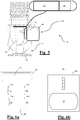
- Fig. 6a shows a top view of the printed circuit board (50) of a sensor base
- Fig. 6b shows the printed circuit board (60) of a sensor module in top view.
- the sensor unit is assembled according to the user's wishes or the conditions in the room to be protected, wherein a choice is made from a number of different sensor modules with mutually different sensor functions, in other words sensor modules whose sensors or detectors are provided for detecting mutually different parameters.
- These parameters may relate to air quality such as temperature, humidity, CO content or the presence of gases that may be injurious to health, or may relate to fire safety, e.g. parameters that are associated with a fire or an incipient fire, such as the presence of certain gases or smoke or a quick temperature rise, or parameters relating to protection against burglary or theft, for example movement, or breaking of glass.
- Other parameters for example such as the open or closed state of a window or a door or the energy consumption in a particular room or in a particular building, may also be monitored by means of a sensor module according to the present invention.
- a modular sensor comprises a sensor base with a printed circuit board (50) on which four sensor positions (51)-(54) are provided.
- the printed circuit board also comprises a battery module (55) and an antenna (56). Data communication takes place for example via an I 2 C bus.
- a connector (51a)-(54a) is provided that is compatible with the standard connector (61) on each sensor module.
- These, four sensor modules may be selected from a number of available sensor modules. Only one of these sensor modules is shown in Fig. 6b .
- the selected sensor modules may be placed in a selected respective sensor position (51)-(54) on the printed circuit board (50) and may be connected via the connectors (51a)-(54a) to the other components (55), (56) of the sensor unit.
- Each sensor module comprises a printed circuit board (60) with smaller dimensions than the printed circuit board (50) of the sensor base. Besides a number of peripheral components that are not shown, a sensor (62) and a standard connector (61) connected to this sensor (62) are provided on this printed circuit board (60).
- This standard connector (61) is complementary to each of the four connectors (51a)-(54a) that are provided on the printed circuit board (50) of the sensor base.
- the printed circuit board (60) shown in Fig. 2b is shown enlarged, so that its dimensions do not have the correct proportions relative to the printed circuit board (50) of the sensor base in Fig. 2a .
- each sensor module has dimensions such that it fits in the free space that is provided at each sensor position (51)-(54) on the printed circuit board (50) of the sensor base.
- Each of the four selected sensor modules is connected to the sensor base by coupling the connector (61) to the connector (51a)-(54a) at a free sensor position. Coupling takes place by means of a click connection.
- each sensor has a unique address
- the data processing means that interact with the sensor unit recognize which type of sensor module is located at each sensor position (51)-(54), and the data received therefrom can be processed and interpreted correctly.
- the modular sensor also comprises three different housings (not shown in the figures), which are adapted to the possible sensor functions.
- the first housing comprises mainly closed walls, which enclose the components almost completely
- the second housing has perforated walls in order to ensure proper action of a sensor module that is designed to detect the presence of a particular gas
- the third housing has closed walls except for one wall, in which an opening is provided in which a lens is placed in order to ensure the correct action of a sensor module that comprises a light sensor.
- the modular sensor according to the present invention also comprises two different battery modules (55) with a mutually different power and a different capacity. Therefore the user can choose the most suitable battery for the sensor unit that he has assembled.
Landscapes
- Health & Medical Sciences (AREA)
- Public Health (AREA)
- Business, Economics & Management (AREA)
- Emergency Management (AREA)
- Fire-Extinguishing By Fire Departments, And Fire-Extinguishing Equipment And Control Thereof (AREA)
Applications Claiming Priority (1)
| Application Number | Priority Date | Filing Date | Title |
|---|---|---|---|
| BE20196008A BE1027943B1 (nl) | 2019-12-31 | 2019-12-31 | Brandbeveiligingsinrichting |
Publications (2)
| Publication Number | Publication Date |
|---|---|
| EP3906976A2 true EP3906976A2 (fr) | 2021-11-10 |
| EP3906976A3 EP3906976A3 (fr) | 2022-02-16 |
Family
ID=69232698
Family Applications (1)
| Application Number | Title | Priority Date | Filing Date |
|---|---|---|---|
| EP20217871.1A Withdrawn EP3906976A3 (fr) | 2019-12-31 | 2020-12-30 | Dispositif de protection contre les incendies |
Country Status (2)
| Country | Link |
|---|---|
| EP (1) | EP3906976A3 (fr) |
| BE (1) | BE1027943B1 (fr) |
Cited By (4)
| Publication number | Priority date | Publication date | Assignee | Title |
|---|---|---|---|---|
| CN115531784A (zh) * | 2022-09-22 | 2022-12-30 | 广东稳固检测鉴定有限公司 | 一种建筑消防火灾检测装置 |
| CN117563185A (zh) * | 2024-01-15 | 2024-02-20 | 南京斯夫特安全工程有限公司 | 一种自动灭火装置的远程监控和报警系统 |
| WO2024125679A1 (fr) * | 2022-12-16 | 2024-06-20 | Megellan, Se | Système de surveillance pour diagnostic et commande sans contact à distance de dispositifs d'extinction d'incendie automatique pour la protection locale de dispositifs électriques |
| CN120919580A (zh) * | 2025-10-14 | 2025-11-11 | 如东信息技术服务(上海)有限公司 | 一种基于多模态感知的智能消防方法及系统 |
Families Citing this family (1)
| Publication number | Priority date | Publication date | Assignee | Title |
|---|---|---|---|---|
| CN113952668A (zh) * | 2021-11-01 | 2022-01-21 | 广东住总建设工程有限公司 | 一种智能感知建筑消防系统 |
Family Cites Families (2)
| Publication number | Priority date | Publication date | Assignee | Title |
|---|---|---|---|---|
| JP5766984B2 (ja) * | 2011-03-16 | 2015-08-19 | 能美防災株式会社 | 消火設備 |
| KR101995990B1 (ko) * | 2019-05-30 | 2019-07-03 | 주식회사 중앙기술단 | 소방기능이 향상된 소방용 제연장치 |
-
2019
- 2019-12-31 BE BE20196008A patent/BE1027943B1/nl not_active IP Right Cessation
-
2020
- 2020-12-30 EP EP20217871.1A patent/EP3906976A3/fr not_active Withdrawn
Cited By (7)
| Publication number | Priority date | Publication date | Assignee | Title |
|---|---|---|---|---|
| CN115531784A (zh) * | 2022-09-22 | 2022-12-30 | 广东稳固检测鉴定有限公司 | 一种建筑消防火灾检测装置 |
| WO2024125679A1 (fr) * | 2022-12-16 | 2024-06-20 | Megellan, Se | Système de surveillance pour diagnostic et commande sans contact à distance de dispositifs d'extinction d'incendie automatique pour la protection locale de dispositifs électriques |
| BE1031091B1 (fr) * | 2022-12-16 | 2024-09-27 | Megellan Se | Système de surveillance pour le diagnostic et le contrôle sans contact à distance de dispositifs d'extinction d'incendie automatiques pour la protection locale de dispositifs électriques |
| GB2640057A (en) * | 2022-12-16 | 2025-10-08 | Se Megellan | The monitoring system for remote contactless diagnostics and control of automatic fire extinguishing devices for local protection of electrical devices |
| CN117563185A (zh) * | 2024-01-15 | 2024-02-20 | 南京斯夫特安全工程有限公司 | 一种自动灭火装置的远程监控和报警系统 |
| CN117563185B (zh) * | 2024-01-15 | 2024-03-19 | 南京斯夫特安全工程有限公司 | 一种自动灭火装置的远程监控和报警系统 |
| CN120919580A (zh) * | 2025-10-14 | 2025-11-11 | 如东信息技术服务(上海)有限公司 | 一种基于多模态感知的智能消防方法及系统 |
Also Published As
| Publication number | Publication date |
|---|---|
| BE1027943B1 (nl) | 2021-08-05 |
| BE1027943A1 (nl) | 2021-07-28 |
| EP3906976A3 (fr) | 2022-02-16 |
Similar Documents
| Publication | Publication Date | Title |
|---|---|---|
| EP3906976A2 (fr) | Dispositif de protection contre les incendies | |
| CN111558190B (zh) | 一种智能消防系统及消防方法 | |
| US8496067B2 (en) | Device and method for protecting an object against fire | |
| US20040188102A1 (en) | Automatic appliance fire extinguisher system | |
| RU2357776C2 (ru) | Система тушения пожара в поезде | |
| BE1029048B1 (nl) | Brandbeveiligingsinrichting | |
| BE1029047B1 (nl) | Brandbeveiligingsinrichting | |
| BE1029049B1 (nl) | Brandbeveiligingsinrichting | |
| Donohue et al. | Fire protection and life safety design in data centers | |
| CN212395686U (zh) | 灭火装置 | |
| CN114053626A (zh) | 地铁工程车电器柜火灾自动监测及灭火装置 | |
| CN210472834U (zh) | 一种具有自动灭火功能的加油机及加油站 | |
| WO2010106381A2 (fr) | Système automatique d'extincteur de feu de moteur pour véhicule à moteur | |
| CN113509669B (zh) | 灭火装置 | |
| CN213100556U (zh) | 灭火装置 | |
| RU2743692C1 (ru) | Система пожаротушения в системе фильтрации воздуха и способ пожаротушения в системе фильтрации воздуха с использованием системы пожаротушения | |
| JPH09313637A (ja) | 自動消火設備における故障発生表示方式 | |
| CN113509671B (zh) | 灭火装置 | |
| RU70141U1 (ru) | Система объемного аэрозольного пожаротушения | |
| WO2021203416A1 (fr) | Dispositif d'extinction d'incendie | |
| RU2625705C1 (ru) | Автоматическое предохранительное устройство систем безопасности в чрезвычайных ситуациях | |
| CN112337004B (zh) | 一种具有自动灭火功能的加油机及加油站 | |
| CN212395685U (zh) | 灭火装置 | |
| ABDULLAH et al. | FIRE PROTECTION SYSTEM | |
| CN113509670A (zh) | 灭火装置 |
Legal Events
| Date | Code | Title | Description |
|---|---|---|---|
| PUAI | Public reference made under article 153(3) epc to a published international application that has entered the european phase |
Free format text: ORIGINAL CODE: 0009012 |
|
| STAA | Information on the status of an ep patent application or granted ep patent |
Free format text: STATUS: THE APPLICATION HAS BEEN PUBLISHED |
|
| AK | Designated contracting states |
Kind code of ref document: A2 Designated state(s): AL AT BE BG CH CY CZ DE DK EE ES FI FR GB GR HR HU IE IS IT LI LT LU LV MC MK MT NL NO PL PT RO RS SE SI SK SM TR |
|
| PUAL | Search report despatched |
Free format text: ORIGINAL CODE: 0009013 |
|
| AK | Designated contracting states |
Kind code of ref document: A3 Designated state(s): AL AT BE BG CH CY CZ DE DK EE ES FI FR GB GR HR HU IE IS IT LI LT LU LV MC MK MT NL NO PL PT RO RS SE SI SK SM TR |
|
| RIC1 | Information provided on ipc code assigned before grant |
Ipc: A62C 37/40 20060101ALI20220110BHEP Ipc: A62C 37/14 20060101ALI20220110BHEP Ipc: A62C 35/10 20060101AFI20220110BHEP |
|
| STAA | Information on the status of an ep patent application or granted ep patent |
Free format text: STATUS: REQUEST FOR EXAMINATION WAS MADE |
|
| 17P | Request for examination filed |
Effective date: 20221104 |
|
| RBV | Designated contracting states (corrected) |
Designated state(s): AL AT BE BG CH CY CZ DE DK EE ES FI FR GB GR HR HU IE IS IT LI LT LU LV MC MK MT NL NO PL PT RO RS SE SI SK SM TR |
|
| RAP1 | Party data changed (applicant data changed or rights of an application transferred) |
Owner name: C-SCAN NV |
|
| STAA | Information on the status of an ep patent application or granted ep patent |
Free format text: STATUS: THE APPLICATION IS DEEMED TO BE WITHDRAWN |
|
| 18D | Application deemed to be withdrawn |
Effective date: 20250701 |