EP3907129B1 - Connecteur et procédé de connexion d'un cadre et d'un longeron d'une structure de fuselage d'un aéronef, structure de fuselage et aéronef - Google Patents
Connecteur et procédé de connexion d'un cadre et d'un longeron d'une structure de fuselage d'un aéronef, structure de fuselage et aéronef Download PDFInfo
- Publication number
- EP3907129B1 EP3907129B1 EP21172756.5A EP21172756A EP3907129B1 EP 3907129 B1 EP3907129 B1 EP 3907129B1 EP 21172756 A EP21172756 A EP 21172756A EP 3907129 B1 EP3907129 B1 EP 3907129B1
- Authority
- EP
- European Patent Office
- Prior art keywords
- connector
- frame
- stringer
- web
- fuselage
- Prior art date
- Legal status (The legal status is an assumption and is not a legal conclusion. Google has not performed a legal analysis and makes no representation as to the accuracy of the status listed.)
- Active
Links
Images


Classifications
-
- B—PERFORMING OPERATIONS; TRANSPORTING
- B64—AIRCRAFT; AVIATION; COSMONAUTICS
- B64C—AEROPLANES; HELICOPTERS
- B64C1/00—Fuselages; Constructional features common to fuselages, wings, stabilising surfaces or the like
- B64C1/06—Frames; Stringers; Longerons ; Fuselage sections
- B64C1/061—Frames
-
- B—PERFORMING OPERATIONS; TRANSPORTING
- B64—AIRCRAFT; AVIATION; COSMONAUTICS
- B64C—AEROPLANES; HELICOPTERS
- B64C1/00—Fuselages; Constructional features common to fuselages, wings, stabilising surfaces or the like
- B64C1/06—Frames; Stringers; Longerons ; Fuselage sections
- B64C1/064—Stringers; Longerons
-
- B—PERFORMING OPERATIONS; TRANSPORTING
- B64—AIRCRAFT; AVIATION; COSMONAUTICS
- B64C—AEROPLANES; HELICOPTERS
- B64C1/00—Fuselages; Constructional features common to fuselages, wings, stabilising surfaces or the like
- B64C1/06—Frames; Stringers; Longerons ; Fuselage sections
- B64C1/068—Fuselage sections
- B64C1/069—Joining arrangements therefor
-
- B—PERFORMING OPERATIONS; TRANSPORTING
- B64—AIRCRAFT; AVIATION; COSMONAUTICS
- B64F—GROUND OR AIRCRAFT-CARRIER-DECK INSTALLATIONS SPECIALLY ADAPTED FOR USE IN CONNECTION WITH AIRCRAFT; DESIGNING, MANUFACTURING, ASSEMBLING, CLEANING, MAINTAINING OR REPAIRING AIRCRAFT, NOT OTHERWISE PROVIDED FOR; HANDLING, TRANSPORTING, TESTING OR INSPECTING AIRCRAFT COMPONENTS, NOT OTHERWISE PROVIDED FOR
- B64F5/00—Designing, manufacturing, assembling, cleaning, maintaining or repairing aircraft, not otherwise provided for; Handling, transporting, testing or inspecting aircraft components, not otherwise provided for
- B64F5/10—Manufacturing or assembling aircraft, e.g. jigs therefor
-
- F—MECHANICAL ENGINEERING; LIGHTING; HEATING; WEAPONS; BLASTING
- F16—ENGINEERING ELEMENTS AND UNITS; GENERAL MEASURES FOR PRODUCING AND MAINTAINING EFFECTIVE FUNCTIONING OF MACHINES OR INSTALLATIONS; THERMAL INSULATION IN GENERAL
- F16B—DEVICES FOR FASTENING OR SECURING CONSTRUCTIONAL ELEMENTS OR MACHINE PARTS TOGETHER, e.g. NAILS, BOLTS, CIRCLIPS, CLAMPS, CLIPS OR WEDGES; JOINTS OR JOINTING
- F16B2/00—Friction-grip releasable fastenings
- F16B2/20—Clips, i.e. with gripping action effected solely by the inherent resistance to deformation of the material of the fastening
- F16B2/22—Clips, i.e. with gripping action effected solely by the inherent resistance to deformation of the material of the fastening of resilient material, e.g. rubbery material
-
- F—MECHANICAL ENGINEERING; LIGHTING; HEATING; WEAPONS; BLASTING
- F16—ENGINEERING ELEMENTS AND UNITS; GENERAL MEASURES FOR PRODUCING AND MAINTAINING EFFECTIVE FUNCTIONING OF MACHINES OR INSTALLATIONS; THERMAL INSULATION IN GENERAL
- F16B—DEVICES FOR FASTENING OR SECURING CONSTRUCTIONAL ELEMENTS OR MACHINE PARTS TOGETHER, e.g. NAILS, BOLTS, CIRCLIPS, CLAMPS, CLIPS OR WEDGES; JOINTS OR JOINTING
- F16B5/00—Joining sheets or plates, e.g. panels, to one another or to strips or bars parallel to them
- F16B5/12—Fastening strips or bars to sheets or plates, e.g. rubber strips, decorative strips for motor vehicles, by means of clips
- F16B5/121—Fastening strips or bars to sheets or plates, e.g. rubber strips, decorative strips for motor vehicles, by means of clips fastened over the edge(s) of the sheet(s) or plate(s)
-
- F—MECHANICAL ENGINEERING; LIGHTING; HEATING; WEAPONS; BLASTING
- F16—ENGINEERING ELEMENTS AND UNITS; GENERAL MEASURES FOR PRODUCING AND MAINTAINING EFFECTIVE FUNCTIONING OF MACHINES OR INSTALLATIONS; THERMAL INSULATION IN GENERAL
- F16B—DEVICES FOR FASTENING OR SECURING CONSTRUCTIONAL ELEMENTS OR MACHINE PARTS TOGETHER, e.g. NAILS, BOLTS, CIRCLIPS, CLAMPS, CLIPS OR WEDGES; JOINTS OR JOINTING
- F16B11/00—Connecting constructional elements or machine parts by sticking or pressing them together, e.g. cold pressure welding
- F16B11/006—Connecting constructional elements or machine parts by sticking or pressing them together, e.g. cold pressure welding by gluing
-
- F—MECHANICAL ENGINEERING; LIGHTING; HEATING; WEAPONS; BLASTING
- F16—ENGINEERING ELEMENTS AND UNITS; GENERAL MEASURES FOR PRODUCING AND MAINTAINING EFFECTIVE FUNCTIONING OF MACHINES OR INSTALLATIONS; THERMAL INSULATION IN GENERAL
- F16B—DEVICES FOR FASTENING OR SECURING CONSTRUCTIONAL ELEMENTS OR MACHINE PARTS TOGETHER, e.g. NAILS, BOLTS, CIRCLIPS, CLAMPS, CLIPS OR WEDGES; JOINTS OR JOINTING
- F16B5/00—Joining sheets or plates, e.g. panels, to one another or to strips or bars parallel to them
- F16B5/06—Joining sheets or plates, e.g. panels, to one another or to strips or bars parallel to them by means of clamps or clips
- F16B5/0607—Joining sheets or plates, e.g. panels, to one another or to strips or bars parallel to them by means of clamps or clips joining sheets or plates to each other
- F16B5/0614—Joining sheets or plates, e.g. panels, to one another or to strips or bars parallel to them by means of clamps or clips joining sheets or plates to each other in angled relationship
Definitions
- the present invention relates to a connector and a method for connecting a frame and a stringer of a fuselage structure of an aircraft, a fuselage structure for an aircraft and an aircraft.
- the frames and stringers are typically attached to each other by means of connectors.
- US 3 600 016 A For example, an angle-shaped connector is described, which is attached to the frame and the stringer, which is S-shaped, by means of rivets.
- Another connector is described in the EP 2 212 191 B1 described, wherein the connector has a foot flange connected to a stringer and a frame flange extending transversely thereto, which is connected to a frame, wherein the foot and frame flanges each Have holes for rivets or other fasteners.
- FIG. 1 Another fuselage structure is shown in the EP 2 301 840 B1 described, wherein the hull structure comprises ⁇ -shaped stringers and annular frames with a C-shaped cross-section which extend beyond the stringers, and wherein L-shaped support elements are provided which are connected by rivets to a foot of the stringer and the frame.
- US 2389767 deals with the attachment of frames and stringers to the outer skin of an aircraft at their intersection point.
- the frames and stringers are designed as trusses.
- US 2018/162510 A1 describes, according to the translation of the abstract in Espacenet, a body of a mobile vehicle.
- the body comprises a skin, a stringer, and a frame.
- the skin includes a first tab and a second tab opposite the first tab.
- the first tab is fixed directly to the skin, and the second tab is fixed directly to the skin.
- the frame includes a cutout, a first foot, and a second foot. The second foot is spaced from the first foot by the cutout.
- US 8480030 B2 describes, according to the translation of the abstract in Espacenet, a structural component for an aircraft or spacecraft having an outer skin and a first reinforcement element running along a first spatial direction on the outer skin. A second reinforcement element runs over the first reinforcement element in a second spatial direction. A base element supports the second reinforcement element on the outer skin, wherein the base element has a through-opening in which the first reinforcement element is held in a form-fitting manner.
- a method for reinforcing an outer skin of an aircraft or spacecraft wherein A first reinforcement element is attached to the outer skin along a first spatial direction. A base element with a through-opening is attached above the first reinforcement element, so that the first reinforcement element is held in the through-opening with a positive fit. A second reinforcement element is attached to the base element in a second spatial direction above the first reinforcement element.
- US 8087621 B2 According to the translation of the abstract in Espacenet, describes a holder for the hole-free and largely tool-free fastening of all types of components, in particular cables, within a conventional fuselage structure of an aircraft with stringers and annular formers, wherein the formers are each provided with an angle at their intersection points: a stringer and an annular former.
- the holder is designed in two parts, with a lower part and an upper part that can be connected to it, wherein the lower part can be pushed onto an angle. By pushing the upper part onto the lower part, the holder is fixed in position at the intersection point in the upper area of an annular former.
- Fixing in its final position is achieved by connecting the holder to a transverse cable holder as a functional element using an expanding pin or other connecting elements.
- Other alternative functional elements for fixing the components such as a longitudinal line holder, a transverse batten, or a longitudinal batten for special installation requirements, can be combined with at least one holder if required to form a holder arrangement of any degree of complexity.
- the object of the present invention is to find improved solutions for hull structures with stringers and frames, in particular solutions that simplify assembly of the hull structure.
- a connector for connecting a frame to a stringer of an aircraft fuselage structure extending transversely thereto.
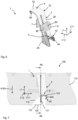
- the connector comprises a base support extending in a connector longitudinal direction, a first connecting portion connected to the base support and extending in a first connector transverse direction, which first connecting portion has, in an end region facing away from the base support, a coupling structure for encompassing an end region of a cross section of the stringer, and a second connecting portion connected to the base support and configured for connection to the frame.
- the first connector transverse direction runs transversely to the connector longitudinal direction.
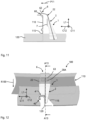
- a fuselage structure for an aircraft comprises a frame, in particular annular, which surrounds a fuselage longitudinal axis and has a stringer recess, a stringer extending along the fuselage longitudinal axis through the stringer recess of the frame, and a connector according to the first aspect of the invention.
- the first connecting section of the connector, together with the coupling structure, encompasses an end region of a cross-section of the stringer.
- the second connecting section of the connector is connected to the frame.
- the connector has a first connecting section with a coupling structure which is designed to encompass one end of the cross section of the stringer.
- the coupling structure can, for example, be hook-shaped and, due to its hook shape, defines a slot which is open on one side, e.g. U-shaped, into which one end of a web of the stringer can be inserted.
- the coupling structure thus encompasses a End region of the cross-section of the stringer.
- the first connecting section extends transversely to a base support of the connector, which can have, for example, an X-shaped, an H-shaped or another cross-sectional profile.
- the coupling structure is provided at an end region of the connecting section facing away from the base support.
- the coupling structure can also be L-shaped with a first section and a second section extending transversely to this, which extends along the longitudinal direction of the connector or along the base support.
- a receiving region for receiving the cross-section of the stringer can be formed between the coupling structure and the base support.
- the end region of the cross-section of the stringer can be received in the slot defined by the hook shape of the coupling structure and/or the stringer can be clamped between the coupling structure and the base support.
- the connector is that the coupling structure encompassing the end of the stringer's cross-section creates a positive connection between the stringer and the connector. This connection can be easily installed by inserting the end of the stringer's cross-section into the hook-shaped coupling structure.
- the cross-sectional profile of the stringer can be hooked or clamped into the coupling structure of the connector. This facilitates installation, particularly in the potentially difficult-to-access intersection area between the frame and stringer. In particular, riveting the connector and stringer is no longer necessary.
- the second connecting portion is oriented in a second connector transverse direction.
- the second connector transverse direction runs transversely to the first connector transverse direction and transversely to the connector longitudinal direction.
- first connector transverse direction is thus directed along the frame
- second connector transverse direction is directed along the stringer or transversely to the frame.
- the second connecting section can therefore be coupled to the frame in a direction transverse to the frame. This improves the support of the frame by the second connecting section and the load transfer between the frame and stringer by the connector.
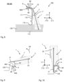
- the second connecting section is arranged in a second end region of the base support with respect to the connector longitudinal direction and extends in the second connector transverse direction, and wherein the second connecting section has, for example, an L-shaped or hook-shaped coupling structure for engaging around an end region of a cross-section of the frame in an end region facing away from the base support.
- the second connecting section can have a transverse web, at the end of which a hook-shaped fold or extension is provided.
- the hook shape of the coupling structure of the second connecting section defines a slot into which one end of a web of the frame can be inserted.
- the end region of the cross-section of the frame can be clamped between the coupling structure and the second end region of the base support.
- the frame can also be connected to the connector in a form-fitting manner, which further facilitates assembly.
Landscapes
- Engineering & Computer Science (AREA)
- Mechanical Engineering (AREA)
- Aviation & Aerospace Engineering (AREA)
- General Engineering & Computer Science (AREA)
- Manufacturing & Machinery (AREA)
- Transportation (AREA)
- Mutual Connection Of Rods And Tubes (AREA)
- Connection Of Plates (AREA)
- Moulding By Coating Moulds (AREA)
Claims (11)
- Connecteur (1) destiné à relier un longeron (110) à une lisse (120) s'étendant transversalement à celui-ci d'une structure de fuselage (100) d'un aéronef (200), comprenant :une poutre de base (2) s'étendant dans une direction longitudinale de connecteur (L1) ;une première section de liaison (4) reliée à la poutre de base (2) et s'étendant dans une première direction transversale de connecteur (C11), qui présente, dans une région d'extrémité (42) opposée à la poutre de base (2), une structure de couplage (40) destinée à entourer une région d'extrémité d'une section transversale de la lisse (120) ; etune deuxième section de liaison (6) reliée à la poutre de base (2), qui est réalisée pour la liaison au longeron (110) ;la deuxième section de liaison (6) étant orientée dans une deuxième direction transversale de connecteur (C12) ; etla deuxième section de liaison (6) étant disposée par rapport à la direction longitudinale de connecteur (L1) dans une deuxième région d'extrémité (22) de la poutre de base (2) et s'étendant dans la deuxième direction transversale de connecteur (C12), et la deuxième section de liaison (6) présentant, dans une région d'extrémité (62) opposée à la poutre de base (2), une structure de couplage (60) destinée à entourer une région d'extrémité d'une section transversale du longeron (110).
- Connecteur (1) selon la revendication 1, la deuxième section de liaison (6) étant réalisée d'une seule pièce avec la poutre de base (2).
- Connecteur (1) selon la revendication 1, la deuxième section de liaison (6) présentant une région de guidage (63) qui est guidée de manière déplaçable dans un guide (28) de la poutre de base (2) dans la direction longitudinale de connecteur (L1), et le guide (28) présentant une première structure de verrouillage (28A), en particulier une nervure élastique, qui vient en prise dans une structure de verrouillage (63A) réalisée dans la région de guidage (63), en particulier sous la forme de dents.
- Connecteur (1) selon l'une quelconque des revendications 1 à 3, présentant en outre :un support de colle (7) en forme de plaque avec une surface (7a) orientée dans la deuxième direction transversale de connecteur (C12), qui est revêtue d'une colle (70) ;le support de colle (7) étant disposé par rapport à la direction longitudinale de connecteur (L1) entre la première et la deuxième section de liaison (4 ; 6) et étant relié à la poutre de base (2).
- Connecteur (1) selon la revendication 1, la deuxième section de liaison (6) étant réalisée en forme de plaque pour l'application contre une région en forme de plaque du longeron (110).
- Connecteur (1) selon la revendication 5, la deuxième section de liaison (6) étant disposée par rapport à la direction longitudinale de connecteur (L1) dans une deuxième région d'extrémité (22) de la poutre de base (2).
- Connecteur (1) selon l'une quelconque des revendications précédentes, la première section de liaison (4) présentant une nervure transversale (43) s'étendant dans la première direction transversale de connecteur (C11), qui est reliée par une première extrémité (43A) à la poutre de base (2),
la structure de couplage (40) présentant une nervure longitudinale (44) s'étendant à partir d'une deuxième extrémité (43B) de la nervure transversale (43) le long d'une première région d'extrémité (21) de la poutre de base (2), qui présente, au niveau d'une extrémité (44B) située à l'opposé de la nervure transversale (43), sur un côté tourné vers la poutre de base (2), un repli en forme de U (44C). - Structure de fuselage (100) pour un aéronef (200), comprenantun longeron (110), en particulier de forme annulaire, entourant un axe longitudinal de fuselage (L100), qui présente un évidement de lisse (115) ;une lisse (120) s'étendant le long de l'axe longitudinal de fuselage (L100) à travers l'évidement de lisse (115) du longeron (110) ; etun connecteur (1) selon l'une quelconque des revendications précédentes ;la première section de liaison (4) du connecteur (1) entourant, avec la structure de couplage (40), une région d'extrémité d'une section transversale de la lisse (120) ; etla deuxième section de liaison (6) du connecteur (1) étant reliée au longeron (110).
- Structure de fuselage (100) selon la revendication 8, la lisse (120) présentant une section transversale en forme de S, et
la structure de couplage (40) entourant la région d'extrémité de la section transversale en forme de S de la lisse (120) par rapport à une direction radiale de fuselage (R100) perpendiculaire à l'axe longitudinal de fuselage (L100). - Procédé de liaison d'un longeron (110) et d'une lisse (120) d'une structure de fuselage (100) selon l'une quelconque des revendications 8 ou 9, comprenant :l'introduction de la région d'extrémité de la section transversale de la lisse (120) dans la structure de couplage (40) de la première section de liaison (4) du connecteur (1) ;le positionnement de la deuxième section de liaison (6) du connecteur (1) sur le longeron (110) ; etla liaison de la deuxième section de liaison (6) du connecteur (1) au longeron (110).
- Aéronef (200) comprenant une structure de fuselage (100 ; 500) selon l'une quelconque des revendications 8 à 9.
Applications Claiming Priority (1)
| Application Number | Priority Date | Filing Date | Title |
|---|---|---|---|
| DE102020205840.7A DE102020205840B3 (de) | 2020-05-08 | 2020-05-08 | Verbinder und Verfahren zum Verbinden eines Spants und eines Stringers einer Rumpfstruktur eines Luftfahrzeugs, Rumpfstruktur und Luftfahrzeug |
Publications (2)
| Publication Number | Publication Date |
|---|---|
| EP3907129A1 EP3907129A1 (fr) | 2021-11-10 |
| EP3907129B1 true EP3907129B1 (fr) | 2025-07-02 |
Family
ID=75870478
Family Applications (1)
| Application Number | Title | Priority Date | Filing Date |
|---|---|---|---|
| EP21172756.5A Active EP3907129B1 (fr) | 2020-05-08 | 2021-05-07 | Connecteur et procédé de connexion d'un cadre et d'un longeron d'une structure de fuselage d'un aéronef, structure de fuselage et aéronef |
Country Status (4)
| Country | Link |
|---|---|
| US (1) | US11643181B2 (fr) |
| EP (1) | EP3907129B1 (fr) |
| DE (1) | DE102020205840B3 (fr) |
| ES (1) | ES3049336T3 (fr) |
Families Citing this family (4)
| Publication number | Priority date | Publication date | Assignee | Title |
|---|---|---|---|---|
| CA3257133A1 (fr) * | 2022-05-13 | 2023-11-16 | Firestorm Labs, Inc. | Véhicule aérien adaptable à la mission et procédés d'assemblage et d'utilisation sur le terrain |
| CN220721406U (zh) * | 2022-06-09 | 2024-04-05 | 影石创新科技股份有限公司 | 一种无人机 |
| EP4545810A1 (fr) * | 2023-10-26 | 2025-04-30 | Airbus Operations GmbH | Clip de fixation pour la fixation d'un objet sur un rail |
| US12486017B2 (en) | 2024-03-13 | 2025-12-02 | Firestorm Labs, Inc. | Additive manufactured integral fastening system for mission adaptable unmanned aerial vehicles |
Family Cites Families (13)
| Publication number | Priority date | Publication date | Assignee | Title |
|---|---|---|---|---|
| US2389767A (en) * | 1943-09-01 | 1945-11-27 | Budd Edward G Mfg Co | Structural frame |
| US3600016A (en) * | 1970-03-23 | 1971-08-17 | Boeing Co | Frame stringer tie |
| US5924650A (en) * | 1996-12-31 | 1999-07-20 | Northrop Grumman Corporation | Method and system for fastening aircraft assemblies |
| US7635106B2 (en) * | 2006-11-30 | 2009-12-22 | The Boeing Company | Composite shear tie |
| DE102007044386A1 (de) * | 2007-09-18 | 2009-04-02 | Airbus Deutschland Gmbh | Strukturbauteil und Verfahren zum Versteifen einer Außenhaut |
| DE102007054053A1 (de) | 2007-11-13 | 2009-05-20 | Airbus Deutschland Gmbh | Kupplungselement zur Verbindung von zwei Längsversteifungselementen |
| US8087621B2 (en) * | 2007-12-20 | 2012-01-03 | Airbus Deutschland Gmbh | Holder for fixing components, in particular lines, inside an aircraft without using holes |
| ES2352941B1 (es) * | 2008-05-16 | 2012-01-25 | Airbus Operations, S.L. | Estructura integrada de aeronave en material compuesto |
| FR2961486B1 (fr) | 2010-06-22 | 2013-03-22 | Airbus Operations Sas | Dispositif pour le maintien d'un matelas isolant et la fixation de systemes |
| FR2962711B1 (fr) * | 2010-07-13 | 2013-03-29 | Airbus Operations Sas | Dispositif de revetement interieur d'une cabine d'aeronef integrant au moins un systeme. |
| GB2528080A (en) * | 2014-07-08 | 2016-01-13 | Airbus Operations Ltd | Structure |
| GB2528078B (en) * | 2014-07-08 | 2020-07-29 | Airbus Operations Ltd | Structure |
| US11524761B2 (en) | 2016-12-09 | 2022-12-13 | The Boeing Company | Stringer-frame intersection of aircraft body |
-
2020
- 2020-05-08 DE DE102020205840.7A patent/DE102020205840B3/de active Active
-
2021
- 2021-05-07 EP EP21172756.5A patent/EP3907129B1/fr active Active
- 2021-05-07 US US17/314,153 patent/US11643181B2/en active Active
- 2021-05-07 ES ES21172756T patent/ES3049336T3/es active Active
Also Published As
| Publication number | Publication date |
|---|---|
| EP3907129A1 (fr) | 2021-11-10 |
| US20210347462A1 (en) | 2021-11-11 |
| DE102020205840B3 (de) | 2021-06-10 |
| ES3049336T3 (en) | 2025-12-16 |
| US11643181B2 (en) | 2023-05-09 |
Similar Documents
| Publication | Publication Date | Title |
|---|---|---|
| EP3907129B1 (fr) | Connecteur et procédé de connexion d'un cadre et d'un longeron d'une structure de fuselage d'un aéronef, structure de fuselage et aéronef | |
| DE10215442B4 (de) | Dreidimensionale Knotenstruktur | |
| DE102009024983A1 (de) | Verbindungsbaugruppe | |
| EP2195234A1 (fr) | Élément de structure et procédé pour rigidifier une enveloppe extérieure | |
| EP2555972A1 (fr) | Élément de raccordement et système de fixation pour rails de siège dans un avion | |
| EP3771650B1 (fr) | Composant de cadre et procédé de fabrication d'un composant de cadre, cadre et structure de fuselage pour un aéronef | |
| EP1939053B1 (fr) | Agencement de fixation, en particulier pour fixer une ferrure de déviation pour une section de sangle d'une ceinture de sécurité dans un véhicule, ainsi que procédé de fixation d'une ferrure de déviation sur une paroi porteuse | |
| DE102009028534A1 (de) | Befestigungssystem in einem Luft- und Raumfahrzeug | |
| EP4069588B1 (fr) | Assemblage de rail de siège pour fixer un assemblage de siège dans un véhicule, utilisation de tel assemblage de rail de siège dans un avion et procédé de fabrication d'un assemblage de rail de siège | |
| EP2786922B1 (fr) | Carrosserie d'un véhicule automobile réalisée en éléments en polymère et connections entre ces éléments | |
| EP2686501B1 (fr) | Module à assembler ainsi que dispositif de suspension pour rails de support et leurs procédés de fabrication. | |
| DE102022125412A1 (de) | Schlosshalter | |
| DE102015116591A1 (de) | Profil zum Verbinden einer Fußbodenstruktur und Dichtungssystem für eine Fußbodenstruktur | |
| DE102020209298A1 (de) | Karosserie für ein Fahrzeug | |
| EP1798186B1 (fr) | Cabine d'ascenseur et méthode de montage de panneaux d'une parroi de cabine | |
| WO2020144122A1 (fr) | Système d'entraînement conçu pour une pièce de toit mobile d'un système de toit d'un véhicule automobile | |
| DE102021101703B4 (de) | Befestigungsklemme für eine verkleidungsanordnung | |
| DE102018203729B4 (de) | Bauteilverbund | |
| EP3468834B1 (fr) | Dispositif et procédé pour fixer un cache de dossier sur un siège de véhicule | |
| DE2446927B2 (de) | Großflächenschalung mit verschieden gekrümmten Flächen | |
| DE102015100997B4 (de) | Verbindungsanordnung eines ersten Karosseriebauteils an einem zweiten Karosseriebauteil für ein Kraftfahrzeug, insbesondere Personenkraftfahrzeug | |
| EP1743863A1 (fr) | Elément de connexion | |
| EP4081716B1 (fr) | Agencement de profilés interconnectés | |
| DE102024134117A1 (de) | Zusammensteckbares Bewehrungselement für einen Bewehrungskorb | |
| DE102007055479A1 (de) | Knotenelement für eine Fachwerkskonstruktion |
Legal Events
| Date | Code | Title | Description |
|---|---|---|---|
| PUAI | Public reference made under article 153(3) epc to a published international application that has entered the european phase |
Free format text: ORIGINAL CODE: 0009012 |
|
| STAA | Information on the status of an ep patent application or granted ep patent |
Free format text: STATUS: THE APPLICATION HAS BEEN PUBLISHED |
|
| AK | Designated contracting states |
Kind code of ref document: A1 Designated state(s): AL AT BE BG CH CY CZ DE DK EE ES FI FR GB GR HR HU IE IS IT LI LT LU LV MC MK MT NL NO PL PT RO RS SE SI SK SM TR |
|
| B565 | Issuance of search results under rule 164(2) epc |
Effective date: 20210929 |
|
| STAA | Information on the status of an ep patent application or granted ep patent |
Free format text: STATUS: REQUEST FOR EXAMINATION WAS MADE |
|
| 17P | Request for examination filed |
Effective date: 20220510 |
|
| RBV | Designated contracting states (corrected) |
Designated state(s): AL AT BE BG CH CY CZ DE DK EE ES FI FR GB GR HR HU IE IS IT LI LT LU LV MC MK MT NL NO PL PT RO RS SE SI SK SM TR |
|
| STAA | Information on the status of an ep patent application or granted ep patent |
Free format text: STATUS: EXAMINATION IS IN PROGRESS |
|
| 17Q | First examination report despatched |
Effective date: 20230315 |
|
| GRAP | Despatch of communication of intention to grant a patent |
Free format text: ORIGINAL CODE: EPIDOSNIGR1 |
|
| STAA | Information on the status of an ep patent application or granted ep patent |
Free format text: STATUS: GRANT OF PATENT IS INTENDED |
|
| INTG | Intention to grant announced |
Effective date: 20241011 |
|
| GRAJ | Information related to disapproval of communication of intention to grant by the applicant or resumption of examination proceedings by the epo deleted |
Free format text: ORIGINAL CODE: EPIDOSDIGR1 |
|
| STAA | Information on the status of an ep patent application or granted ep patent |
Free format text: STATUS: EXAMINATION IS IN PROGRESS |
|
| GRAP | Despatch of communication of intention to grant a patent |
Free format text: ORIGINAL CODE: EPIDOSNIGR1 |
|
| STAA | Information on the status of an ep patent application or granted ep patent |
Free format text: STATUS: GRANT OF PATENT IS INTENDED |
|
| INTC | Intention to grant announced (deleted) | ||
| INTG | Intention to grant announced |
Effective date: 20250131 |
|
| GRAS | Grant fee paid |
Free format text: ORIGINAL CODE: EPIDOSNIGR3 |
|
| GRAA | (expected) grant |
Free format text: ORIGINAL CODE: 0009210 |
|
| STAA | Information on the status of an ep patent application or granted ep patent |
Free format text: STATUS: THE PATENT HAS BEEN GRANTED |
|
| AK | Designated contracting states |
Kind code of ref document: B1 Designated state(s): AL AT BE BG CH CY CZ DE DK EE ES FI FR GB GR HR HU IE IS IT LI LT LU LV MC MK MT NL NO PL PT RO RS SE SI SK SM TR |
|
| REG | Reference to a national code |
Ref country code: GB Ref legal event code: FG4D Free format text: NOT ENGLISH |
|
| REG | Reference to a national code |
Ref country code: CH Ref legal event code: EP |
|
| REG | Reference to a national code |
Ref country code: DE Ref legal event code: R096 Ref document number: 502021007882 Country of ref document: DE |
|
| REG | Reference to a national code |
Ref country code: DE Ref legal event code: R081 Ref document number: 502021007882 Country of ref document: DE Owner name: PREMIUM AEROTEC GMBH, DE Free format text: FORMER OWNER: ANMELDERANGABEN UNKLAR / UNVOLLSTAENDIG, 80297 MUENCHEN, DE |
|
| REG | Reference to a national code |
Ref country code: IE Ref legal event code: FG4D Free format text: LANGUAGE OF EP DOCUMENT: GERMAN |
|
| REG | Reference to a national code |
Ref country code: NL Ref legal event code: MP Effective date: 20250702 |
|
| PG25 | Lapsed in a contracting state [announced via postgrant information from national office to epo] |
Ref country code: PT Free format text: LAPSE BECAUSE OF FAILURE TO SUBMIT A TRANSLATION OF THE DESCRIPTION OR TO PAY THE FEE WITHIN THE PRESCRIBED TIME-LIMIT Effective date: 20251103 |
|
| PG25 | Lapsed in a contracting state [announced via postgrant information from national office to epo] |
Ref country code: NL Free format text: LAPSE BECAUSE OF FAILURE TO SUBMIT A TRANSLATION OF THE DESCRIPTION OR TO PAY THE FEE WITHIN THE PRESCRIBED TIME-LIMIT Effective date: 20250702 |
|
| REG | Reference to a national code |
Ref country code: ES Ref legal event code: FG2A Ref document number: 3049336 Country of ref document: ES Kind code of ref document: T3 Effective date: 20251216 |
|
| PG25 | Lapsed in a contracting state [announced via postgrant information from national office to epo] |
Ref country code: IS Free format text: LAPSE BECAUSE OF FAILURE TO SUBMIT A TRANSLATION OF THE DESCRIPTION OR TO PAY THE FEE WITHIN THE PRESCRIBED TIME-LIMIT Effective date: 20251102 |
|
| PG25 | Lapsed in a contracting state [announced via postgrant information from national office to epo] |
Ref country code: NO Free format text: LAPSE BECAUSE OF FAILURE TO SUBMIT A TRANSLATION OF THE DESCRIPTION OR TO PAY THE FEE WITHIN THE PRESCRIBED TIME-LIMIT Effective date: 20251002 |
|
| REG | Reference to a national code |
Ref country code: LT Ref legal event code: MG9D |
|
| PG25 | Lapsed in a contracting state [announced via postgrant information from national office to epo] |
Ref country code: FI Free format text: LAPSE BECAUSE OF FAILURE TO SUBMIT A TRANSLATION OF THE DESCRIPTION OR TO PAY THE FEE WITHIN THE PRESCRIBED TIME-LIMIT Effective date: 20250702 |
|
| PG25 | Lapsed in a contracting state [announced via postgrant information from national office to epo] |
Ref country code: HR Free format text: LAPSE BECAUSE OF FAILURE TO SUBMIT A TRANSLATION OF THE DESCRIPTION OR TO PAY THE FEE WITHIN THE PRESCRIBED TIME-LIMIT Effective date: 20250702 |
|
| PG25 | Lapsed in a contracting state [announced via postgrant information from national office to epo] |
Ref country code: GR Free format text: LAPSE BECAUSE OF FAILURE TO SUBMIT A TRANSLATION OF THE DESCRIPTION OR TO PAY THE FEE WITHIN THE PRESCRIBED TIME-LIMIT Effective date: 20251003 |
|
| PG25 | Lapsed in a contracting state [announced via postgrant information from national office to epo] |
Ref country code: SE Free format text: LAPSE BECAUSE OF FAILURE TO SUBMIT A TRANSLATION OF THE DESCRIPTION OR TO PAY THE FEE WITHIN THE PRESCRIBED TIME-LIMIT Effective date: 20250702 Ref country code: CZ Free format text: LAPSE BECAUSE OF FAILURE TO SUBMIT A TRANSLATION OF THE DESCRIPTION OR TO PAY THE FEE WITHIN THE PRESCRIBED TIME-LIMIT Effective date: 20250702 |
|
| PG25 | Lapsed in a contracting state [announced via postgrant information from national office to epo] |
Ref country code: LV Free format text: LAPSE BECAUSE OF FAILURE TO SUBMIT A TRANSLATION OF THE DESCRIPTION OR TO PAY THE FEE WITHIN THE PRESCRIBED TIME-LIMIT Effective date: 20250702 |
|
| PG25 | Lapsed in a contracting state [announced via postgrant information from national office to epo] |
Ref country code: PL Free format text: LAPSE BECAUSE OF FAILURE TO SUBMIT A TRANSLATION OF THE DESCRIPTION OR TO PAY THE FEE WITHIN THE PRESCRIBED TIME-LIMIT Effective date: 20250702 Ref country code: BG Free format text: LAPSE BECAUSE OF FAILURE TO SUBMIT A TRANSLATION OF THE DESCRIPTION OR TO PAY THE FEE WITHIN THE PRESCRIBED TIME-LIMIT Effective date: 20250702 |
|
| PG25 | Lapsed in a contracting state [announced via postgrant information from national office to epo] |
Ref country code: RS Free format text: LAPSE BECAUSE OF FAILURE TO SUBMIT A TRANSLATION OF THE DESCRIPTION OR TO PAY THE FEE WITHIN THE PRESCRIBED TIME-LIMIT Effective date: 20251002 |
|
| PG25 | Lapsed in a contracting state [announced via postgrant information from national office to epo] |
Ref country code: SM Free format text: LAPSE BECAUSE OF FAILURE TO SUBMIT A TRANSLATION OF THE DESCRIPTION OR TO PAY THE FEE WITHIN THE PRESCRIBED TIME-LIMIT Effective date: 20250702 |
|
| PG25 | Lapsed in a contracting state [announced via postgrant information from national office to epo] |
Ref country code: DK Free format text: LAPSE BECAUSE OF FAILURE TO SUBMIT A TRANSLATION OF THE DESCRIPTION OR TO PAY THE FEE WITHIN THE PRESCRIBED TIME-LIMIT Effective date: 20250702 |
|
| PG25 | Lapsed in a contracting state [announced via postgrant information from national office to epo] |
Ref country code: SK Free format text: LAPSE BECAUSE OF FAILURE TO SUBMIT A TRANSLATION OF THE DESCRIPTION OR TO PAY THE FEE WITHIN THE PRESCRIBED TIME-LIMIT Effective date: 20250702 Ref country code: EE Free format text: LAPSE BECAUSE OF FAILURE TO SUBMIT A TRANSLATION OF THE DESCRIPTION OR TO PAY THE FEE WITHIN THE PRESCRIBED TIME-LIMIT Effective date: 20250702 |