EP3907151B1 - Lotionspumpe - Google Patents
Lotionspumpe Download PDFInfo
- Publication number
- EP3907151B1 EP3907151B1 EP19906831.3A EP19906831A EP3907151B1 EP 3907151 B1 EP3907151 B1 EP 3907151B1 EP 19906831 A EP19906831 A EP 19906831A EP 3907151 B1 EP3907151 B1 EP 3907151B1
- Authority
- EP
- European Patent Office
- Prior art keywords
- movable portion
- elastic restoring
- lotion pump
- piston rod
- restoring mechanism
- Prior art date
- Legal status (The legal status is an assumption and is not a legal conclusion. Google has not performed a legal analysis and makes no representation as to the accuracy of the status listed.)
- Active
Links
Images











Classifications
-
- B—PERFORMING OPERATIONS; TRANSPORTING
- B05—SPRAYING OR ATOMISING IN GENERAL; APPLYING FLUENT MATERIALS TO SURFACES, IN GENERAL
- B05B—SPRAYING APPARATUS; ATOMISING APPARATUS; NOZZLES
- B05B11/00—Single-unit hand-held apparatus in which flow of contents is produced by the muscular force of the operator at the moment of use
- B05B11/01—Single-unit hand-held apparatus in which flow of contents is produced by the muscular force of the operator at the moment of use characterised by the means producing the flow
- B05B11/10—Pump arrangements for transferring the contents from the container to a pump chamber by a sucking effect and forcing the contents out through the dispensing nozzle
- B05B11/1042—Components or details
- B05B11/1043—Sealing or attachment arrangements between pump and container
- B05B11/1046—Sealing or attachment arrangements between pump and container the pump chamber being arranged substantially coaxially to the neck of the container
- B05B11/1047—Sealing or attachment arrangements between pump and container the pump chamber being arranged substantially coaxially to the neck of the container the pump being preassembled as an independent unit before being mounted on the container
-
- B—PERFORMING OPERATIONS; TRANSPORTING
- B05—SPRAYING OR ATOMISING IN GENERAL; APPLYING FLUENT MATERIALS TO SURFACES, IN GENERAL
- B05B—SPRAYING APPARATUS; ATOMISING APPARATUS; NOZZLES
- B05B11/00—Single-unit hand-held apparatus in which flow of contents is produced by the muscular force of the operator at the moment of use
- B05B11/01—Single-unit hand-held apparatus in which flow of contents is produced by the muscular force of the operator at the moment of use characterised by the means producing the flow
- B05B11/10—Pump arrangements for transferring the contents from the container to a pump chamber by a sucking effect and forcing the contents out through the dispensing nozzle
- B05B11/1001—Piston pumps
-
- B—PERFORMING OPERATIONS; TRANSPORTING
- B05—SPRAYING OR ATOMISING IN GENERAL; APPLYING FLUENT MATERIALS TO SURFACES, IN GENERAL
- B05B—SPRAYING APPARATUS; ATOMISING APPARATUS; NOZZLES
- B05B11/00—Single-unit hand-held apparatus in which flow of contents is produced by the muscular force of the operator at the moment of use
- B05B11/01—Single-unit hand-held apparatus in which flow of contents is produced by the muscular force of the operator at the moment of use characterised by the means producing the flow
- B05B11/10—Pump arrangements for transferring the contents from the container to a pump chamber by a sucking effect and forcing the contents out through the dispensing nozzle
- B05B11/1001—Piston pumps
- B05B11/1023—Piston pumps having an outlet valve opened by deformation or displacement of the piston relative to its actuating stem
-
- B—PERFORMING OPERATIONS; TRANSPORTING
- B05—SPRAYING OR ATOMISING IN GENERAL; APPLYING FLUENT MATERIALS TO SURFACES, IN GENERAL
- B05B—SPRAYING APPARATUS; ATOMISING APPARATUS; NOZZLES
- B05B11/00—Single-unit hand-held apparatus in which flow of contents is produced by the muscular force of the operator at the moment of use
- B05B11/01—Single-unit hand-held apparatus in which flow of contents is produced by the muscular force of the operator at the moment of use characterised by the means producing the flow
- B05B11/10—Pump arrangements for transferring the contents from the container to a pump chamber by a sucking effect and forcing the contents out through the dispensing nozzle
- B05B11/1042—Components or details
- B05B11/1059—Means for locking a pump or its actuation means in a fixed position
- B05B11/106—Means for locking a pump or its actuation means in a fixed position in a retracted position, e.g. in an end-of-dispensing-stroke position
-
- B—PERFORMING OPERATIONS; TRANSPORTING
- B05—SPRAYING OR ATOMISING IN GENERAL; APPLYING FLUENT MATERIALS TO SURFACES, IN GENERAL
- B05B—SPRAYING APPARATUS; ATOMISING APPARATUS; NOZZLES
- B05B11/00—Single-unit hand-held apparatus in which flow of contents is produced by the muscular force of the operator at the moment of use
- B05B11/01—Single-unit hand-held apparatus in which flow of contents is produced by the muscular force of the operator at the moment of use characterised by the means producing the flow
- B05B11/10—Pump arrangements for transferring the contents from the container to a pump chamber by a sucking effect and forcing the contents out through the dispensing nozzle
- B05B11/1042—Components or details
- B05B11/1073—Springs
-
- B—PERFORMING OPERATIONS; TRANSPORTING
- B05—SPRAYING OR ATOMISING IN GENERAL; APPLYING FLUENT MATERIALS TO SURFACES, IN GENERAL
- B05B—SPRAYING APPARATUS; ATOMISING APPARATUS; NOZZLES
- B05B11/00—Single-unit hand-held apparatus in which flow of contents is produced by the muscular force of the operator at the moment of use
- B05B11/01—Single-unit hand-held apparatus in which flow of contents is produced by the muscular force of the operator at the moment of use characterised by the means producing the flow
- B05B11/10—Pump arrangements for transferring the contents from the container to a pump chamber by a sucking effect and forcing the contents out through the dispensing nozzle
- B05B11/1042—Components or details
- B05B11/1073—Springs
- B05B11/1074—Springs located outside pump chambers
-
- B—PERFORMING OPERATIONS; TRANSPORTING
- B05—SPRAYING OR ATOMISING IN GENERAL; APPLYING FLUENT MATERIALS TO SURFACES, IN GENERAL
- B05B—SPRAYING APPARATUS; ATOMISING APPARATUS; NOZZLES
- B05B11/00—Single-unit hand-held apparatus in which flow of contents is produced by the muscular force of the operator at the moment of use
- B05B11/01—Single-unit hand-held apparatus in which flow of contents is produced by the muscular force of the operator at the moment of use characterised by the means producing the flow
- B05B11/10—Pump arrangements for transferring the contents from the container to a pump chamber by a sucking effect and forcing the contents out through the dispensing nozzle
- B05B11/1042—Components or details
- B05B11/1073—Springs
- B05B11/1077—Springs characterised by a particular shape or material
-
- B—PERFORMING OPERATIONS; TRANSPORTING
- B65—CONVEYING; PACKING; STORING; HANDLING THIN OR FILAMENTARY MATERIAL
- B65D—CONTAINERS FOR STORAGE OR TRANSPORT OF ARTICLES OR MATERIALS, e.g. BAGS, BARRELS, BOTTLES, BOXES, CANS, CARTONS, CRATES, DRUMS, JARS, TANKS, HOPPERS, FORWARDING CONTAINERS; ACCESSORIES, CLOSURES, OR FITTINGS THEREFOR; PACKAGING ELEMENTS; PACKAGES
- B65D47/00—Closures with filling and discharging, or with discharging, devices
- B65D47/04—Closures with discharging devices other than pumps
- B65D47/20—Closures with discharging devices other than pumps comprising hand-operated members for controlling discharge
- B65D47/24—Closures with discharging devices other than pumps comprising hand-operated members for controlling discharge with poppet valves or lift valves, i.e. valves opening or closing a passageway by a relative motion substantially perpendicular to the plane of the seat
-
- A—HUMAN NECESSITIES
- A47—FURNITURE; DOMESTIC ARTICLES OR APPLIANCES; COFFEE MILLS; SPICE MILLS; SUCTION CLEANERS IN GENERAL
- A47K—SANITARY EQUIPMENT; ACCESSORIES THEREFOR, e.g. TOILET ACCESSORIES
- A47K5/00—Holders or dispensers for soap, toothpaste or the like
- A47K5/06—Dispensers for soap
- A47K5/12—Dispensers for soap for liquid or pasty soap
- A47K5/1202—Dispensers for soap for liquid or pasty soap dispensing dosed volume
- A47K5/1204—Dispensers for soap for liquid or pasty soap dispensing dosed volume by means of a rigid dispensing chamber and pistons
- A47K5/1205—Dispensing from the top of the dispenser with a vertical piston
-
- B—PERFORMING OPERATIONS; TRANSPORTING
- B05—SPRAYING OR ATOMISING IN GENERAL; APPLYING FLUENT MATERIALS TO SURFACES, IN GENERAL
- B05B—SPRAYING APPARATUS; ATOMISING APPARATUS; NOZZLES
- B05B11/00—Single-unit hand-held apparatus in which flow of contents is produced by the muscular force of the operator at the moment of use
- B05B11/01—Single-unit hand-held apparatus in which flow of contents is produced by the muscular force of the operator at the moment of use characterised by the means producing the flow
- B05B11/10—Pump arrangements for transferring the contents from the container to a pump chamber by a sucking effect and forcing the contents out through the dispensing nozzle
- B05B11/1042—Components or details
- B05B11/1066—Pump inlet valves
- B05B11/1067—Pump inlet valves actuated by pressure
Definitions
- the present invention relates to a lotion pump, and especially relates to an all-plastic lotion pump.
- Lotion pump is broadly used in daily chemicals such as hand sanitizer, shower gel and the like, for pumping the product out from a container such as a bottle, for use.
- the lotion pumps sold in the market are mostly provided with metal springs, which can restore the lotion pump after a user have pressed the lotion pump to pump an amount of product out for use, thus ready for the next use.
- plastic spring for replacing metal spring, i.e. an all-plastic pump is proposed.
- Plastic spring is often in the form of plastic helical spring, plastic arc spring, bellow spring, and the like.
- the present plastic spring has some drawbacks, for example when the plastic spring is compressed for a long time, it will yield, thus the spring force of the plastic spring will deteriorate, or even fail to function as a spring.
- one solution is to set an all-plastic pump in the form of locking at upper position, and when the lotion pump is in a non-use state, the plastic spring is in a state free of pressing and is relaxed.
- Fig. 29 shows an exemplary lotion pump with a plastic spring.
- the lotion pump 1 has a press head 10, a toothed sleeve 20, a cylinder 30 and a piston rod 40, one end of a spring 50 is connected to the piston rod 40, and the other end thereof is connected to the cylinder 30.
- the piston rod 40 moves down accordingly, so that the spring 50 is compressed, and when the pressure on the press head 10 is removed, the press head 10 restores by means of the elastic force of the spring 50.
- 29 is a lotion pump in the form of locking at upper position, and in the non-use state, for example when the product is transported and is displayed for sale, the press head 10 is in its highest position of the stroke, so that the spring 50 is in the state that has the least compress force, therefore, the spring 50 will not yield, which result in failure of the spring, due to being compressed in the non-use state.
- the above mentioned lotion pump is a lotion pump of the type of locking at upper position.
- a lotion pump of the type of locking at upper position sometimes it is hard to meet the requirement of package for E-business.
- the lotion pump of the type of locking at upper position has a larger height in its original and non-used state, thus result in a higher requirement for the height of the product box, good shelf and the like.
- US 2015136810 A1 discloses a press type liquid pump, wherein two bearing faces are at difference elevations that alternatively engage with upper ends of the elastic strip to realize shifting between the locked and open states.
- WO 9325318 A1 discloses a cream dispenser, wherein a fixed feeding piston linked to a top housing by a shoulder can plunge into a longitudinally movable feeding cylinder which can be pressed by a spring element against transversely movable bevels by means of two cams.
- CN 207482522 U discloses a liquid pump, wherein the raised supporting face of the relaxation ring is in contact with the upper base of the elastic mechanism.
- the present invention is to overcome the above-mentioned technical problem of the existing lotion pump.
- the object of the present invention is to provide a lotion pump with improved structure, which can protect a plastic spring of the lotion pump from yielding due to being pressed in non-used state, thus provide the same with longer life time, meanwhile it can realize locking at lower position, thus satisfy requirement of E-business transportation.
- the lotion pump of the present invention according to a first aspect is mounted on a container for dispensing product in the container, the lotion pump includes a movable portion and a stationary portion, when used, the movable portion can move relative to the container, and the stationary portion remain station relative to the container, wherein the lotion pump further includes:
- the shifting mechanism by means of the provision of the shifting mechanism, movement of the movable parts, such as the press head, can shift a supporting seat between the first position and the second position, so as to select to apply a compress force on the elastic restoring mechanism, or reduce the compress force act on the elastic restoring mechanism, or even disengage from the elastic restoring mechanism.
- the elastic restoring mechanism can be applied with a tiny pressure, or is not pressed.
- Such a structure is especially advantageous for the elastic spring, and can help in extending its lifetime. And, it can be seen that such a structure of the lotion pump can realize the form of locking at lower position, thus it can meet the requirement of package in E-business transportation.
- the shifting mechanism is provided on the movable portion.
- the shifting mechanism further includes a first mating part, and a second mating part is formed on the elastic restoring mechanism, when the movable portion moves relative to the container, the first mating part cooperates with the second mating part, so that one end of the elastic restoring mechanism is moved between the first position and the second position.
- the elastic restoring mechanism includes a spring and a spring supporting seat, the spring supporting seat is positioned at one end of the spring, and the second mating part is formed on the spring supporting seat.
- One of the first mating part and the second mating part is a helical rib
- the other one of the first mating part and the second mating part is a helical slot
- the helical rib can mate into the helical slot, so that when the movable portion rotates, the helical slot and the helical rib act with each other, so that one end of the elastic restoring mechanism moves between the first position and the second position.
- the interaction between the helical slot and the helical rib can move the supporting seat into the second position at the same time, so that the spring is loaded.
- the helical rib can disengage from the helical slot, and the size and the relative position of the helical rib and the helical slot are set such that as the movable portion rotates, the helical rib disengages from the helical slot prior to alignment of a locking block to a cutout.
- a lower end of the rib can abut against the supporting seat, so that it is held in the second position, and it can also prevent the helical slot from undesirably entering again into the helical rib when the press head of the lotion pump is pressed.
- the movable portion and the stationary portion can also be provided differently from the above mentioned, for example the cylinder is of the movable portion, and the piston rod and the piston are of the stationary portion.
- the first mating part includes a guide strip
- the second mating part includes a cutout, by means of rotation of the piston rod, the guide strip aligns to the cutout, thus allowing one end of the elastic restoring mechanism to move between the first position and the second position.
- an upper locking block is provided above the guide strip, and/or a lower locking block is provided below the guide strip; and a stop is formed above and/or below the second mating part, and the stop mates with the upper locking block and/or the lower locking, so that the movable portion can only rotate in a preset direction.
- the movable portion can include a press head, a piston rod and a piston, wherein the piston rod is connected at a lower part of the press head, and the piston is provided on the piston rod,
- the stationary portion includes a toothed sleeve and a cylinder, wherein the cylinder is connected to the toothed sleeve, and at least the portion of the piston rod provided with the piston extends into inside of the cylinder, wherein a locking block is formed at one of a peripheral surface of the piston rod and a top of the toothed sleeve, and a cutout is formed at the other of the peripheral surface of the piston rod and the top of the toothed sleeve, thus by rotating the piston rod, the locking block aligns with the cutout, thus allowing the press head and the piston rod to move upwardly.
- the shifting mechanism includes a first mating part, and a second mating part is formed on the elastic restoring mechanism, wherein the first mating portion is a reversed snap ring, by pulling the movable portion upwardly, the second mating part can move through the reversed snap ring so as to move from a first position to a second position, and is held in the second position by the reversed snap ring.
- the stationary portion includes a toothed sleeve and a cylinder, wherein the cylinder is connected to the toothed sleeve, and at least a portion provided with the piston of the piston rod extends into inside of the cylinder, wherein one of the one end of the elastic restoring mechanism and the outer wall of the cylinder includes a guide block, and the other of the one end of the elastic restoring mechanism and the outer wall of the cylinder is formed with a trough, the guide block is at least partially received in the trough.
- Engagement between the trough and the guide block can guarantee that the supporting seat moves in a longitudinal line.
- the movable portion includes a press head, a piston rod and a piston, wherein the piston rod is connected at a lower part of the press head, and the piston is provided on the piston rod, wherein a first mating part is formed on a peripheral surface of the piston rod and/or of the piston.
- the movable portion includes a press head, a piston rod, a piston and a casing, wherein the piston rod is connected at a lower part of the press head, and the piston is provided on the piston rod, wherein the casing is sleeved outside the piston rod and/or the piston, and the first mating part is formed on an outer surface of the casing.
- the elastic restoring mechanism includes at least one elastic strip.
- the elastic restoring mechanism further includes: an annular upper spring seat, on which an upper end of the elastic strip is connected; and/or an annular lower spring seat, on which a lower end of the elastic strip is connected.
- the elastic strip is connected to the upper spring seat and/or the lower spring seat by a pivot, wherein when the elastic restoring mechanism is compressed, the pivot pivots and folds.
- a first guide slot is formed on one of the inner side of the upper spring seat and the stationary portion, a first guide strip is formed on the other of the inner side of the upper spring seat and the stationary portion, and the first guide slot mates with the first guide strip; and/or a second guide slot is formed on one of the inner side of the lower spring seat and the stationary portion, a second guide strip is formed on the other of the inner side of the lower spring seat and the stationary portion, the second guide slot mates with the second guide strip.
- a reversed snap part is provided at a lower portion of the stationary portion, the reversed snap part secures the lower spring seat of the spring.
- the elastic strip extends around at least a portion of the peripheral surface of the cylinder.
- Figs.1-11b shows a lotion pump 100 of a first embodiment of the present invention, with a relaxing mechanism provided in the lotion pump 100.
- Fig.1 shows a side view of the lotion pump 100
- Fig.2 shows a partial sectional perspective view of the lotion pump 100, from which an inside structure of the lotion pump can be seen.
- the lotion pump 100 includes a press head 110, a toothed sleeve 120 and a cylinder 130.
- the cylinder 130 connects to the toothed sleeve 120, an elastic restoring mechanism, such as a spring 140, is provided around periphery of the cylinder 130 outside the cylinder 130.
- the lotion pump 100 also includes a piston rod 150 with one end thereof connected to the press head 110 and the other end thereof provided with a piston and extending into inside of the cylinder 130.
- the lotion pump 100 of the present invention further includes a supporting seat 160, the supporting seat 160 is provided inside the cylinder 130 and around the piston rod 150, so that an upper end of the spring 140 is supported on the supporting seat 160, and a lower end of the spring is supported on the cylinder 130, specifically on a lower portion of the cylinder 130.
- the press head 110 can move together with the piston rod 150 and the piston on the piston rod 150 relative to the cylinder 130, the toothed sleeve 120 and etc., and the cylinder 130, the toothed sleeve 120 and etc., always remain a fixed or stationary state relative to a container when they are mounted on the container,. So, in the lotion pump 100, the press head 110, the piston rod 150 and the piston on the piston rod 150 can be deemed as configuring at least a part of a movable portion of the lotion pump 100, and correspondingly, the cylinder 130 and the toothed sleeve 120 configures at least a part of a stationary portion.
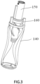
- Fig.3 shows connection between parts functioning for relaxing of the lotion pump 100 of the present invention.
- Figs.4 and 5 respectively show sectional views of the lotion pump 100 in a non-used state and an open state.
- the piston rod 150 and the supporting seat 160 interact with each other, so that a function of a relaxing mechanism is realized. Specifically as disclosed in the followings.
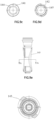
- Figs.6a-6d show views of the supporting seat 160 of the lotion pump 100 of the first embodiment, wherein Figs.6a and 6b are sectional views of the supporting seat 160 taken in different directions, Fig.6c is a top view of the supporting seat 160, and Fig.6d is a perspective view of the supporting seat 160.
- the supporting seat 160 is generally shaped in a ring surrounding and provided outside the piston rod 150, or in other words sleeved outside the piston rod 150 (see Fig.2 ).
- At an outer side of the supporting seat 160 at least one guide block 161, preferably a pair of opposed guide blocks 161, is provided, which cooperates with a trough 131 in the cylinder 130, for limiting movement of the supporting seat 160, which will be described in the detail in the followings.
- At least one helical slot 162 is provided in an inner side of the ring-shaped body of the supporting seat 160.
- the supporting seat 160 includes two helical slots 162 provided to oppose to each other.
- at least one helical rib 151 is provided on a periphery surface of the piston rod 150.
- a ring-shaped flange 153 is provided above the helical rib 151, when the supporting seat 160 is at its highest position of the stroke, the ring-shaped flange 153 stops the supporting seat 160, preventing the supporting seat 160 from continuing moving upward so that the helical slot 162 disengages from the helical rib 151.
- a locking block 152 is further provided on the piston rod 150, mating with a cutout 121 formed on the toothed sleeve 120, particularly on the top of the toothed sleeve 120, allowing the press head 110 to shift between a locked state and a standby state, as described more detailed below.
- Figs.8a-8c a perspective view shows schematically mating between the piston rod 150 and the supporting seat 160.
- the press head 110 is rotated and then in turn rotates the piston rod 150 connected thereto, by means of interaction between the helical slot 162 and the helical rib 151, the supporting seat 160 can move downwardly relative to the piston rod 150, as shown in Fig.8b .
- further rotation of the piston rod 150 can disengage the helical rib 151 of the piston rod 150 from the helical slot 162 of the supporting seat 160, and bring a lower end surface of the helical rib 151 into abutment against an upper surface of the supporting seat 160, as the state shown in Fig.8c .
- the spring 140 can be brought from a non-standby state into a compressed standby state.
- Figs.9a-9d show various views of the spring 140, wherein Fig.9a shows a front view of the spring 140, Fig.9b shows a perspective view of the spring 140, Fig.9c shows a top view of the spring 140, and Fig.9d shows a bottom view of the spring 140.
- the spring 140 has an annular upper spring seat 141 and an annular lower spring seat 142, ends of at least one elastic strip 143 is respectively connected to the upper spring seat 141 and the lower spring seat 142.
- the spring 140 shown in the drawings includes two elastic spring strips 143, while one skilled in the art can know that any proper number of elastic strips 143 can be provided as desired, for example one elastic strip 143, or three or more elastic strips 143.
- a pivot 146 can be provided at the ends of the elastic strip 143 connecting to the upper spring seat 141 and/or lower spring seat 142.
- the pivot 146 is sheet shaped, and when the spring 140 is pressed, the sheet shaped pivot 146 can pivot and be fold onto the upper spring seat 141/lower spring seat 142.
- At least one guide slot 144 is formed at inner side of the upper spring seat 141 of the spring 140, which mates with a spring guide strip 132 (see Fig.10 ) formed on peripheral surface of the cylinder 130, for guiding movement of the spring 140, as described in detail below.
- an inner side of the lower spring seat 142 of the spring 140 can also be formed with a guide slot 145, which can be mate with a corresponding spring guide strip 132 on the cylinder 130.
- the elastic strip 143 is shaped so that a projection of the elastic strip in an axial direction of the lotion pump 100 is generally arc shaped.
- the elastic strip 143 extends around at least a portion of the periphery of the cylinder, as shown in Figs.9e and 9f .
- Figs.9a-9f show a preferred structure of the spring 140.
- Such a structure can be modified, or some part of the structure can be omitted.
- the guide slot 144 and guide slot 145 respectively provided on the upper spring seat 141 and the lower spring seat 142 can be omitted.
- the spring 140 can do not include the upper spring seat 141 and the lower spring seat 142, and the individual elastic strips 143 can be respectively secured on the support seating 160 and a lower portion of the cylinder 130.
- Fig.10 shows a front view of the cylinder 130.
- an outer wall of the cylinder is formed with a trough 131, in which a guide block 161 of the supporting seat 160 is slidably received, so that the supporting seat 160 can only longitudinally move relative to the cylinder 130, and cannot rotate.
- the periphery of the cylinder 130 is also provided with a spring guide strip 132, which mates with the guide slot 144 in the upper spring seat 141 and/or the guide slot 145 in the lower spring seat 142 of the spring 140, thus functioning to guide the spring 140.
- the guide slot and the guide strip can be interchanged, i.e. the upper spring seat 141/lower spring seat 142 are provided with guide strips, and the guide slot is formed on the cylinder.
- a reversed snap part 133 which mates with the lower spring seat 142 of the spring 140, is formed at a bottom of an outer wall of the cylinder 130, for securing the lower spring seat 142, preventing upward movement of the lower spring seat 142 relative to the cylinder 130.
- Figs.11a and 11b respectively show front and top views of the toothed sleeve 120.
- a cutout 121 is formed on the toothed sleeve 120, especially on the top of the toothed sleeve 120.
- the lotion pump 100 is in a locked state, which is useful in the situation that the lotion pump 100 is transported, sold and the like.
- the supporting seat 160 in the lotion pump 100 is in its highest position of its stroke, and the helical slot 162 of the supporting seat 160 mates with the helical rib 151 of the piston rod 150.
- the user rotates the press head 110 in an opening direction, thus rotate the piston rod 150 connected to the press head 110 together.
- the helical rib 151 on the outer surface of the piston rod 150 interacts with the helical slot 162 on the supporting seat 160, so that the supporting seat 160 moves downwardly relative to the piston rod 150, i.e. moves in a direction towards the spring 140, until the helical rib 151 disengages from the helical slot 162.
- the supporting seat 160 applies a compress force on the spring, and the compress force gradually increases.
- the piston rod 150 is kept on rotating, so as to offset the helical slot 162 from the helical rib 151, so that a lower end of the helical rib 151 abuts against an upper surface of the helical slot 162.
- the spring 140 is brought from a free and non-standby state into a standby state.
- the locking block 152 can move into a position in which it aligns to the cutout 121 on the top of the toothed sleeve 120. At this time, the locking block 152 can extend through the cutout 121, so that the press head 110 springs upwardly into the standby state.
- the press head 110 After the use, if it is needed to return the lotion pump 100 back to its locked state, the press head 110 is pressed downwardly to its lowest pint of stroke, then the press head 110 is rotated in a closing direction opposite to its opening direction.
- the helical rib 151 of the piston rod 150 will once again mate in the helical slot 162 of the supporting seat 160, and as the piston rod 150 rotates, the helical rib 151 interacts with the helical slot 162, moving the supporting seat 160 upwardly, i.e. moving in a direction away from the spring 140, so that the compress force applied on the spring 140 reduces, thus the spring 140 turns back to its non-standby state. Even, the supporting seat 160 can disengage from contacting with the spring 140.
- the helical rib 151 can shift the spring 140 between a non-standby state and a standby state, i.e. functioning as a shifting mechanism.
- the helical rib 151 can also be deemed to have separation and reunion function between the spring 140 and movable portion of the lotion pump 100 by the supporting seat 160.
- the relative position and size of the helical rib 151 and the locking block 152 of the piston rod 150 are set such that the helical rib 151 disengages from the helical slot 162 prior to alignment between the locking block 152 and the cutout 121 in the toothed sleeve 120.
- the helical rib 151 can be prevented from entering again into the helical slot 162 during pressing the press head 110 to pump the product.
- a longitudinal length of the locking block 152 is preferably set such that during the process that the press head 110 is pressed to pump the product and the press head 110 springs back, the locking block 152 always moves within the cutout 121, thus during use, the helical rib 151 can be prevented from entering again into the helical slot 162 due to rotation of the press head 110.
- the shifting mechanism can also be formed on any other part and other position of the movable portion of the lotion pump 100, which is also within the scope of the present invention.
- the shifting mechanism can also be formed on the stationary portion of the lotion pump 100, for example a helical rib can be formed on an inner wall of the cylinder 130, and correspondingly, a helical slot can be formed on a periphery of the supporting seat 160.
- the piston rod formed with helical rib is a stationary portion of the lotion pump, while the cylinder is a movable portion (such a case will be explained in detail in the following embodiments). These also do not fall beyond the scope of the present invention.
- Figs.12a-15b show a lotion pump 200 of a second embodiment of the present invention.
- features identical or similar to those of the lotion pump 100 of the first embodiment will not be described in detail, and only the features of the lotion pump 200 of the second embodiment not included in the first embodiment will be described. Unless contrarily expressed or structural conflicting, the features disclosed in the first embodiment may also be applied to the second embodiment.
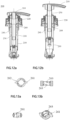
- Figs.12a and 12b respectively show the lotion pump 200 in the locked state and the lotion pump 200 in the standby state.
- the lotion pump 200 includes a press head 210, a toothed sleeve 220, a cylinder 230, a spring 240 and a piston rod 250.
- a supporting seat 260 is provided in the cylinder 230.
- a trough 231 is formed in the outer wall of the cylinder 230, a guide block 261 of the supporting seat 260 is slidably received in the trough 231, so that the supporting seat 260 can only longitudinally move relative to the piston rod 250.
- Figs.13a-13d show various views of the supporting seat 260 in the lotion pump 200 of the second embodiment, wherein Fig.13a is a top view of the supporting seat 260, Fig.13b is a sectional view of the supporting seat 260, Fig.13c is another sectional view of the supporting seat 260, and Fig.13d is a perspective view of the supporting seat 260.
- the support ring 260 in the lotion pump 200 of the second embodiment is also generally ring shaped, having at least one guide block 261 (two guide blocks 261 provided in opposite is shown in the drawings).
- At least one supporting seat cutout preferably a pair of supporting seat cutouts 262 provided in opposite shown in the figure, is formed in an inner side of the supporting seat 260.
- at least one supporting seat stop 263 is further formed at inner side of the supporting seat 260, preferably the upper and lower portions of inner side of the supporting seat 260 are respectively formed with the supporting seat stop 263.
- Figs.14a and 14b respectively show front and perspective views of the piston rod 250.
- a guide strip 251 is formed on periphery of the piston rod 250.
- the piston rod 250 is preferably further formed with an upper locking block 252 and a lower locking block 253 respectively positioned on upper and lower sides of the guide strip 251.
- the upper locking block 252 and the lower locking block 253 mate with the supporting seat stop 263, so that the piston 250 can only rotate in a preset direction.
- the piston rod 250 and the supporting seat 260 mate with each other as shown in Figs.15a and 15b .
- the operation of the lotion pump 200 of the second embodiment will be described below with reference to Figs.12a, 12b , 15a and 15b .
- the supporting seat 260 is positioned above the guide strip 251 of the piston rod 250, and the supporting seat cutout 262 offsets from the guide strip 251, so that the position of the supporting seat 260 fixes with respect to the piston rod 250.
- the press head 210 When the lotion pump 200 is to be used, the press head 210 is rotated in an opening direction, so that the supporting seat cutout 262 aligns to the guide strip 251, at this time, the press head 210 can be manually pulled upward to its highest point of stroke, the supporting seat 260 moves relative to the piston rod 250 below the guide strip 251. Then, rotation of the press head 210 continues, so that the supporting seat cutout 262 once again offsets from the guide strip 251, so that the guide strip 251 limits the supporting seat 260 at a position below it. At this time, the spring 240 is loaded, so that pumping is possible by pressing the press head 210.
- the press head 210 can be rotated in an oppose direction, so that the supporting seat cutout 262 once again aligns to the guide strip 251, then the press head can be manually pressed to its lowest point of stroke, the rotation of the press head 210 continuous, so that the supporting seat cutout 262 offsets from the guide strip 251, and the guide strip 251 holds the supporting seat 260 at a position thereabove.
- the piston rod 250 is provided with the upper locking block 252 and the lower locking block 253, and the supporting seat 260 is provided with the supporting seat stop 263, the upper and lower locking blocks 252, 253 interact with the supporting seat stop 263, so that the user can rotate the press head 210 only in a preset direction.
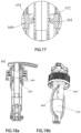
- Figs.16a-17 show a lotion pump 300 of a third embodiment of the present invention.
- features identical or similar to those of the lotion pumps of the first and second embodiments will not be described in detail, and only the features of the lotion pump 300 of the third embodiment not included in the first and second embodiments will be described. Unless contrarily expressed or structural conflicting, the features disclosed in the first and second embodiments also may be applied to the third embodiment.
- the lotion pump 300 includes a press head 310, a toothed sleeve 320, a cylinder 330, a spring 340 and a piston rod 350, and the lotion pump 300 also includes a supporting seat 360.
- a reversed snap ring 351 is formed on the piston rod 350
- a first chamfer 352 facing upwardly is formed on the reversed snap ring 351
- a second chamfer 361 facing downwardly is formed correspondingly on the supporting seat 360.
- the press head 310 In the locked position shown in Fig.16a , the press head 310 is at the lowest point of its stroke, the supporting seat 360 is positioned above the reversed snap ring 351. After the press head 310 is rotated to an opening position, the press head 310 is pulled to the highest point of its stroke, during which the reversed snap ring 351 moves upwardly through the supporting seat 360 and above the supporting seat 360. At this time, the structure of the reversed snap ring 351 prevents the supporting seat 360 returning back again to the position above the reversed snap ring 351. Thus, the lotion pump 300 is held in the standby state shown in Fig.16b .
- Figs.18a and 18b show a lotion pump 400 of a fourth embodiment of the present invention.
- features identical or similar to those of the lotion pumps of the first to third embodiments will not be described in detail, and only the features of the lotion pump 400 of the fourth embodiment not included in the first to third embodiments will be described. Unless contrarily expressed or structural conflicting, the features disclosed in the first to third embodiments may also be applied to the fourth embodiment.
- the lotion pump 400 of the fourth embodiment is substantially identical to the lotion pump 100 of the first embodiment, and it is distinguished only in that the upper spring seat 141 and the lower spring seat 142 of the spring 140 is omitted.
- the upper end of the elastic strip of the spring 440 is directly connected to the supporting seat 460, and the lower end of the elastic strip is directly connected to the lower part of the cylinder 430.
- Figs.19a-22 show a lotion pump 500 of a fifth embodiment of the present invention.
- features identical or similar to those of the lotion pumps of the first to fourth embodiments will not be described in detail, and only the features of the lotion pump 500 of the fifth embodiment not included in the first to fourth embodiments will be described. Unless contrarily expressed or structural conflicting, the features disclosed in the first to fourth embodiments may also be applied to the fifth embodiment.
- Fig.19 shows a sectional view of a lotion pump 500 in a lower locked state
- Fig.19b shows a sectional view of the lotion pump 500 in a standby state.
- the press head 510 of the lotion pump 500 is provided at its lower part with an outer thread, and is secured in a locked position via a thread connection between the press head 510 and the toothed sleeve 520.
- Fig.20 shows the outer thread 511 on the press head 510 more clearly.
- an inner thread mating with the outer thread 511 is formed in an opening of the toothed sleeve.
- the piston rod 550 of the lotion pump 500 is formed separately from the piston 580, and they are connected together.
- a helical rib functioning as a shifting part can be formed on the outer surface of any one of the piston rod 550 and the piston 580, or is partially formed on the outer surface of the piston rod 550 and partially formed on the outer surface of the piston 580.
- a helical rib 581 is formed on the outer surface of the piston 580.
- Figs.24-27 show variations of a part of the structure of the fifth embodiment.
- the piston rod 650 and the piston 680 are also separately formed, and then connected together.
- a casing 670 is additionally provided, the outer surface of the casing 670 is formed with a helical rib 671 or other types of shifting parts.
- the casing 670 is sleeved on the outer surfaces of the piston rod 650 and the piston 680 connected together, as shown in Fig.27 .
- such structure as rib 672 is also formed on an inner surface of the casing 670, which facilitates in close engagement to the outer surface of the piston rod 650 and/or the piston 680.
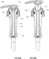
- Figs.28a and 28b show a lotion pump 700 of a sixth embodiment of the present invention.
- features identical or similar to those of the lotion pumps of the first to fifth embodiments and variations thereof will not be described in detail, and only the features unique in the lotion pump 700 of the sixth embodiment will be described. And, unless contrarily expressed or structural conflicting, the features disclosed in the first to fifth embodiments may also be applied to the fifth embodiment.
- Fig.28a shows a sectional view of a lotion pump 700 in a lower locked state
- Fig.28b shows a sectional view of the lotion pump 700 in a standby state.
- the lotion pump 700 includes a press head 710, and a cylinder 730 is connected to a lower part of the press head 710. So, in the sixth embodiment, movement of the press head 710 (such as rotation or moving up and down) brings the cylinder 730 to move together, so that the press head 710 and the cylinder 730 configures at least a part of the movable portion of the lotion pump.
- a spring bracket 770 is connected on the toothed sleeve 720, one end of the spring 750 (specifically the lower end shown in Figs.28a and 28b ) is supported on the spring bracket 770, and the other end of the spring 750 (upper end in the drawings) is supported on the spring supporting seat 760.
- the spring bracket 770 is further fixed with the piston rod 740, and the piston on one end of the piston rod 740 extends into the cylinder 730.
- a first protrusion 731 and a second protrusion 732 are formed on an outer wall of the cylinder 730, and a slot 761 is formed on an inner surface of the spring supporting seat 760. As the press head 710 and the cylinder 730 move up and down, the slot 761 can mate respectively with one of the first protrusion 731 and the second protrusion 732.
- the spring 750 when the slot 761 mates with the protrusion 731 positioned above (the state shown in Fig.28a ), the spring 750 is in non-loaded state, and when the slot 761 mates with the second protrusion 732 positioned below, or even is below the second protrusion 732, the spring 750 is in its loaded state.
- the sixth embodiment it is the first protrusion 731 and second protrusion 732 formed on outer surface of the cylinder 730 that function as the shifting mechanism.
- the embodied structures of helical rib, guide strip and the like mentioned in the preceding embodiments are also applied to the sixth embodiment.
Landscapes
- Engineering & Computer Science (AREA)
- Mechanical Engineering (AREA)
- Health & Medical Sciences (AREA)
- Public Health (AREA)
- Reciprocating Pumps (AREA)
- Closures For Containers (AREA)
Claims (12)
- Lotionspumpe (100, 400, 500, 700), die an einem Behälter zum Abgeben von Erzeugnis in dem Behälter angebracht werden kann, wobei die Lotionspumpe (100, 400, 500, 700) einen beweglichen Abschnitt sowie einen stationären Abschnitt enthält, in Funktion der bewegliche Abschnitt relativ zu dem Behälter bewegt werden kann und der stationäre Abschnitt relativ zu dem Behälter stationär bleibt, wobei die Lotionspumpe (100, 400, 500, 700) des Weiteren umfasst:einen elastischen Rückstellmechanismus, dessen eines Ende mit dem beweglichen Abschnitt in Kontakt oder verbunden ist und dessen anderes Ende an dem stationären Abschnitt befestigt ist; sowieeinen Verschiebemechanismus, der so eingerichtet ist, dass er mit dem elastischen Rückstellmechanismus so in Eingriff ist, dass, wenn sich der bewegliche Abschnitt in einer ersten Richtung dreht und/oder sich nach oben bewegt, das eine Ende des elastischen Rückstellmechanismus sich relativ zu dem beweglichen Abschnitt an eine erste Position bewegt, so dass der elastische Rückstellmechanismus gespannt und in einen Bereitschaftszustand gebracht wird, und, wenn sich der bewegliche Abschnitt in einer zweiten Richtung entgegengesetzt zu der ersten Richtung dreht und/oder sich nach unten bewegt, das eine Ende des elastischen Rückstellmechanismus sich relativ zu dem beweglichen Abschnitt an eine zweite Position bewegt, so dass der elastische Rückstellmechanismus in einen Nicht-Bereitschaftszustand gebracht wird;wobei sich der Verschiebemechanismus an dem beweglichen Abschnitt befindet;wobei der Verschiebemechanismus einen ersten Eingriffsteil enthält und ein zweiter Eingriffsteil an dem elastischen Rückstellmechanismus ausgebildet ist, der erste Eingriffsteil, wenn sich der bewegliche Abschnitt relativ zu dem Behälter bewegt, mit dem zweiten Eingriffsteil so zusammenwirkt, dass das eine Ende des elastischen Rückstellmechanismus zwischen der ersten Position und der zweiten Position bewegt wird;der elastische Rückstellmechanismus eine Feder (140, 440) sowie eine Federlagerungs-Aufnahme (160, 460) enthält, die Federlagerungs-Aufnahme (160, 460) an dem einen Ende der Feder (140, 440) positioniert ist und der zweite Eingriffsteil an der Federlagerungs-Aufnahme (160, 460) ausgebildet ist;dadurch gekennzeichnet, dassder erste Eingriffsteil oder der zweite Eingriffsteil eine spiralförmige Rippe (151, 581, 671) ist und der andere von dem ersten Eingriffsteil und dem zweiten Eingriffsteil ein spiralförmiger Schlitz (162) ist, wobei die spiralförmige Rippe (151, 581, 671) so in den spiralförmigen Schlitz (162) eingreifen kann, dass, wenn sich der bewegliche Abschnitt dreht, der spiralförmige Schlitz (162) und die spiralförmige Rippe (151, 581, 671) so zusammenwirken, dass sich das eine Ende des elastischen Rückstellmechanismus zwischen der ersten Position und der zweiten Position bewegt.
- Lotionspumpe (200), die an einem Behälter zum Abgeben von Erzeugnis in dem Behälter angebracht werden kann, wobei die Lotionspumpe (200) einen beweglichen Abschnitt und einen stationären Abschnitt enthält, in Funktion der bewegliche Abschnitt relativ zu dem Behälter bewegt werden kann, und der stationäre Abschnitt relativ zu dem Behälter stationär bleibt, wobei die Lotionspumpe (200) des Weiteren umfasst:einen elastischen Rückstellmechanismus, dessen eines Ende mit dem beweglichen Abschnitt in Kontakt oder verbunden ist und dessen anderes Ende an dem stationären Abschnitt befestigt ist; sowieeinen Verschiebemechanismus, der so eingerichtet ist, dass er mit dem elastischen Rückstellmechanismus so in Eingriff ist, dass, wenn sich der bewegliche Abschnitt in einer ersten Richtung dreht und/oder sich nach oben bewegt, das eine Ende des elastischen Rückstellmechanismus sich relativ zu dem beweglichen Abschnitt an eine erste Position bewegt, so dass der elastische Rückstellmechanismus gespannt und in einen Bereitschaftszustand gebracht wird, und, wenn sich der bewegliche Abschnitt in einer zweiten Richtung entgegengesetzt zu der ersten Richtung dreht und/oder sich nach unten bewegt, das eine Ende des elastischen Rückstellmechanismus sich relativ zu dem beweglichen Abschnitt an eine zweite Position bewegt, sodass der elastische Rückstellmechanismus in einen Nicht-Bereitschaftszustand gebracht wird;wobei sich der Verschiebemechanismus an dem beweglichen Abschnitt befindet;wobei der Verschiebemechanismus einen ersten Eingriffsteil enthält und ein zweiter Eingriffsteil an dem elastischen Rückstellmechanismus ausgebildet ist, der erste Eingriffsteil, wenn sich der bewegliche Abschnitt relativ zu dem Behälter bewegt, mit dem zweiten Eingriffsteil so zusammenwirkt, dass das eine Ende des elastischen Rückstellmechanismus zwischen der ersten Position und der zweiten Position bewegt wird;dadurch gekennzeichnet, dassder erste Eingriffsteil eine Führungsleiste (251) enthält und der zweite Eingriffsteil einen Ausschnitt (262) enthält und durch Drehung des beweglichen Abschnitts die Führungsleiste (251) auf den Ausschnitt (262) ausgerichtet wird und dadurch zulässt, dass sich das eine Ende des elastischen Rückstellmechanismus zwischen der ersten Position und der zweiten Position bewegt;und wobei ein oberer Verriegelungsblock (252) oberhalb der Führungsleiste (251) vorhanden ist und/oder ein unterer Verriegelungsblock (253) unterhalb der Führungsleiste (251) vorhanden ist; undein Anschlag oberhalb und/oder unterhalb des zweiten Eingriffsteils ausgebildet ist, wobei der Anschlag mit dem oberen Verriegelungsblock (252) und/oder dem unteren Verriegelungsblock so in Eingriff kommt, dass sich der bewegliche Abschnitt nur in einer voreingestellten Richtung drehen kann.
- Lotionspumpe (100) nach Anspruch 1, wobei der bewegliche Abschnitt einen Drückkopf (110), eine Kolbenstange (150) sowie einen Kolben enthält, wobeidie Kolbenstange (150) mit einem unteren Teil des Drückkopfes (110) verbunden ist, und der Kolben an der Kolbenstange (150) vorhanden ist, der stationäre Abschnitt eine mit Zähnen versehene Hülse (120) sowie einen Zylinder (130) enthält,wobei der Zylinder mit der mit Zähnen versehenen Hülse (120) verbunden ist, und wenigstens der mit dem Kolben versehene Abschnitt der Kolbenstange (150) sich in das Innere des Zylinders (130) hinein erstreckt;wobei ein Verriegelungsblock (152) an einer Umfangsfläche der Kolbenstange oder einem oberen Ende der mit Zähnen versehenen Hülse (120) ausgebildet ist, und ein Ausschnitt (121) an dem anderen Element von der Umfangsfläche der Kolbenstange (150) und dem oberen Ende der mit Zähnen versehenen Hülse (120) ausgebildet ist, so dass durch Drehen der Kolbenstange (150) der Verriegelungsblock (152) auf den Ausschnitt (121) ausgerichtet wird, so dass sich der Drückkopf (110) und die Kolbenstange (150) nach oben bewegen können.
- Lotionspumpe (100) nach Anspruch 3, wobei, wenn sich der bewegliche Abschnitt dreht, sich die spiralförmige Rippe (151) aus dem spiralförmigen Schlitz (162) lösen kann, und eine Größe sowie eine relative Position der spiralförmigen Rippe (151) und des spiralförmigen Schlitzes (162) so eingestellt sind, dass, wenn sich der bewegliche Abschnitt dreht, sich die spiralförmige Rippe (151) vor Ausrichtung des Verriegelungsblocks (152) auf den Ausschnitt (121) aus dem spiralförmigen Schlitz (162) löst.
- Lotionspumpe (300), die an einem Behälter zum Abgeben von Erzeugnis in dem Behälter angebracht werden kann, wobei die Lotionspumpe (300) einen beweglichen Abschnitt sowie einen stationären Abschnitt enthält, in Funktion der bewegliche Abschnitt relativ zu dem Behälter bewegt werden kann und der stationäre Abschnitt relativ zu dem Behälter stationär bleibt, wobei die Lotionspumpe (300) des Weiteren umfasst:einen elastischen Rückstellmechanismus, dessen eines Ende mit dem beweglichen Abschnitt in Kontakt oder verbunden ist und dessen anderes Ende an dem stationären Abschnitt befestigt ist; sowieeinen Verschiebemechanismus, der so eingerichtet ist, dass er mit dem elastischen Rückstellmechanismus so in Eingriff ist, dass, wenn sich der bewegliche Abschnitt in einer ersten Richtung dreht und/oder sich nach oben bewegt, das eine Ende des elastischen Rückstellmechanismus sich relativ zu dem beweglichen Abschnitt an eine erste Position bewegt, so dass der elastische Rückstellmechanismus gespannt und in einen Bereitschaftszustand gebracht wird, und, wenn sich der bewegliche Abschnitt in einer zweiten Richtung entgegengesetzt zu der ersten Richtung dreht und/oder sich nach unten bewegt, das eine Ende des elastischen Rückstellmechanismus sich relativ zu dem beweglichen Abschnitt an eine zweite Position bewegt, sodass der elastische Rückstellmechanismus in einen Nicht-Bereitschaftszustand gebracht wird;wobei sich der Verschiebemechanismus an dem beweglichen Abschnitt befindet;wobei der Verschiebemechanismus einen ersten Eingriffsteil enthält und ein zweiter Eingriffsteil an dem elastischen Rückstellmechanismus ausgebildet ist, der erste Eingriffsteil, wenn sich der bewegliche Abschnitt relativ zu dem Behälter bewegt, mit dem zweiten Eingriffsteil so zusammenwirkt, dass das eine Ende des elastischen Rückstellmechanismus zwischen der ersten Position und der zweiten Position bewegt wird;dadurch gekennzeichnet, dassder erste Eingriffsteil ein umgekehrter Sicherungsring (351) ist, indem der bewegliche Abschnitt nach oben gezogen wird, sich der zweite Eingriffsteil durch den umgekehrten Sicherungsring (351) hindurch bewegen kann und sich so von einer ersten Position an eine zweite Position bewegt und durch den umgekehrten Sicherungsring (351) in der zweiten Position gehalten wird.
- Lotionspumpe (100, 200, 400) nach Anspruch 1, 2 oder 5, wobei der stationäre Abschnitt eine mit Zähnen versehene Hülse (120, 220) sowie einen Zylinder (130, 230, 430) enthält, der bewegliche Abschnitt einen Drückkopf sowie eine Kolbenstange (150, 250) enthält, der Zylinder (130, 230, 430) mit der mit Zähnen versehenen Hülse (120, 220) verbunden ist, und wenigstens ein mit dem Kolben versehener Abschnitt der Kolbenstange (150, 250) sich in das Innere des Zylinders (130, 230) hinein erstreckt, wobei das eine Ende des elastischen Rückstellmechanismus oder eine Außenwand des Zylinders (130, 230, 430) einen Führungsblock (161, 261) enthält und das andere Element von dem elastischen Rückstellmechanismus und der Außenwand des Zylinders (130, 230, 430) mit einer Mulde (131, 231) versehen ist, der Führungsblock (161, 261) wenigstens teilweise in der Mulde (131, 231) aufgenommen ist; und/oder
wobei der bewegliche Abschnitt einen Drückkopf (110, 210, 310, 510), eine Kolbenstange (150, 250, 350, 550, 650, 750) sowie einen Kolben enthält, wobei die Kolbenstange (150, 250, 350, 550, 650, 750) mit einem unteren Teil des Drückkopfes (110, 210, 310, 510) verbunden ist, und der Kolben an der Kolbenstange (150, 250, 350, 550, 650, 750) vorhanden ist, wobei der erste Eingriffsteil an einer Umfangsfläche der Kolbenstange (150, 250, 350, 550, 650, 750) und/oder des Kolbens vorhanden ist. - Lotionspumpe (500) nach Anspruch 1, 2 oder 5, wobei der bewegliche Abschnitt einen Drückkopf (510), eine Kolbenstange (650), einen Kolben sowie ein Gehäuse (670) enthält, wobei die Kolbenstange (650) mit einem unteren Teil des Drückkopfes (510) verbunden ist und der Kolben an der Kolbenstange (650) vorhanden ist, wobei das Gehäuse (670) außen auf die Kolbenstange (650) und/oder den Kolben aufgesetzt ist und der erste Eingriffsteil an einer Außenfläche des Gehäuses (670) ausgebildet ist.
- Lotionspumpe (100) nach Anspruch 1, 2 oder 5, wobei der elastische Rückstellmechanismus enthält:wenigstens eine elastische Leiste (143);eine ringförmige obere Feder-Aufnahme (141), mit der ein oberes Ende der elastischen Leiste (143) verbunden ist; und/odereine ringförmige untere Feder-Aufnahme (142), mit der ein unteres Ende der elastischen Leiste (143) verbunden ist.
- Lotionspumpe (100) nach Anspruch 8, wobei die elastische Leiste (143) mit der oberen Feder-Aufnahme (141) und/oder der unteren Feder-Aufnahme (142) über ein Drehgelenk (146) verbunden ist, wobei, wenn der elastische Rückstellmechanismus zusammengedrückt wird, das Drehgelenk (146) geschwenkt und zusammengeklappt wird.
- Lotionspumpe (100) nach Anspruch 8, wobei ein erster Führungsschlitz (144) an der Innenseite der oberen Feder-Aufnahme (141) oder dem stationären Abschnitt ausgebildet ist, eine erste Führungsleiste (132) an dem anderen Element von der Innenseite und der oberen Feder-Aufnahme (141) und dem stationären Abschnitt ausgebildet ist und der erste Führungsschlitz (144) mit der ersten Führungsleiste (132) in Eingriff kommt; und/oder
ein zweiter Führungsschlitz (145) an der Innenseite der unteren Feder-Aufnahme (142) oder dem stationären Abschnitt ausgebildet ist, eine zweite Führungsleiste (132) an dem anderen Element von der Innenseite der unteren Feder-Aufnahme (151) und dem stationären Abschnitt ausgebildet ist und der zweite Führungsschlitz (145) mit dem zweiten Führungsstreifen (132) in Eingriff kommt. - Lotionspumpe (100) nach einem der Ansprüche 8 - 10, wobei ein umgekehrter Einrastteil (133) an einem unteren Teil des stationären Abschnitts vorhanden ist und der umgekehrte Einrastteil (133) die untere Feder-Aufnahme (142) der Feder (140) sichert.
- Lotionspumpe (100) nach Anspruch 8, wobei sich die elastische Leiste (143), in einer axialen Richtung der Lotionspumpe (100) gesehen, um wenigstens einen Abschnitt der Umfangsfläche eines Zylinders (130) der Lotionspumpe (100) herum erstreckt.
Applications Claiming Priority (2)
| Application Number | Priority Date | Filing Date | Title |
|---|---|---|---|
| CN201910004781.4A CN111392232B (zh) | 2019-01-03 | 2019-01-03 | 乳液泵 |
| PCT/CN2019/108973 WO2020140513A1 (zh) | 2019-01-03 | 2019-09-29 | 乳液泵 |
Publications (3)
| Publication Number | Publication Date |
|---|---|
| EP3907151A1 EP3907151A1 (de) | 2021-11-10 |
| EP3907151A4 EP3907151A4 (de) | 2022-09-28 |
| EP3907151B1 true EP3907151B1 (de) | 2025-05-21 |
Family
ID=71407245
Family Applications (1)
| Application Number | Title | Priority Date | Filing Date |
|---|---|---|---|
| EP19906831.3A Active EP3907151B1 (de) | 2019-01-03 | 2019-09-29 | Lotionspumpe |
Country Status (6)
| Country | Link |
|---|---|
| US (1) | US11638925B2 (de) |
| EP (1) | EP3907151B1 (de) |
| JP (1) | JP2022516184A (de) |
| KR (1) | KR102785861B1 (de) |
| CN (2) | CN120421139A (de) |
| WO (1) | WO2020140513A1 (de) |
Families Citing this family (12)
| Publication number | Priority date | Publication date | Assignee | Title |
|---|---|---|---|---|
| CN120421139A (zh) * | 2019-01-03 | 2025-08-05 | 丁要武 | 乳液泵 |
| USD975544S1 (en) * | 2019-10-10 | 2023-01-17 | Yonwoo Co., Ltd. | Pump head for packaging container |
| US11332279B2 (en) * | 2020-09-25 | 2022-05-17 | World Club Supply Corporation | Liquid dispenser apparatus |
| JP1716860S (ja) * | 2020-12-17 | 2022-06-07 | 抽出用ポンプのヘッド | |
| CN114906474A (zh) * | 2021-02-10 | 2022-08-16 | 丁要武 | 弹性复位机构及包括该弹性复位机构的按压泵 |
| CN113716204B (zh) * | 2021-05-07 | 2024-02-06 | 丁要武 | 一种可矫正的按压泵 |
| CN115158873B (zh) * | 2022-07-25 | 2025-02-28 | 浙江正庄实业有限公司 | 耐压高分子旋转锁扣按压真空膏霜瓶及其制备方法 |
| CN117508888A (zh) * | 2022-12-29 | 2024-02-06 | 天舟医疗(苏州)有限公司 | 全塑按压泵 |
| CN116062308B (zh) * | 2023-02-20 | 2024-09-27 | 厦门戴达科技有限公司 | 一种全塑液体泵 |
| CH721179A1 (de) * | 2023-10-05 | 2025-04-15 | Alpla Werke Alwin Lehner Gmbh & Co Kg | Pumpspender |
| CN117696293A (zh) * | 2023-12-29 | 2024-03-15 | 天舟医疗(苏州)有限公司 | 下位锁头全塑按压泵 |
| WO2026048005A1 (ja) * | 2024-08-30 | 2026-03-05 | 東京ライト工業株式会社 | ポンプディスペンサー |
Family Cites Families (21)
| Publication number | Priority date | Publication date | Assignee | Title |
|---|---|---|---|---|
| US3452905A (en) * | 1968-02-16 | 1969-07-01 | Leeds & Micallef | Self-sealing leak-proof pump |
| DE4219474A1 (de) * | 1992-06-13 | 1993-12-16 | Katz Otto | Cremespender |
| US5518147A (en) * | 1994-03-01 | 1996-05-21 | The Procter & Gamble Company | Collapsible pump chamber having predetermined collapsing pattern |
| EP1266696A1 (de) * | 2001-06-13 | 2002-12-18 | Taplast S.p.A. | Balgpumpe zur Abgabe von Gasflüssigkeitmischungen |
| JP3089465U (ja) * | 2002-04-22 | 2002-10-25 | リビング ファウンテン プラスチック インダストリアル カンパニー リミテッド | 圧縮式液状物流出装置 |
| AU2002328625A1 (en) * | 2002-08-16 | 2004-03-03 | Advanex Inc. | Pump unit and container |
| TWM244868U (en) | 2003-09-16 | 2004-10-01 | Brooklands Entpr Co Ltd | Extrusion device |
| CN102464133A (zh) * | 2010-11-03 | 2012-05-23 | 余姚晟祺塑业有限公司 | 全塑乳液泵 |
| KR101290829B1 (ko) * | 2011-10-17 | 2013-08-07 | 김정수 | 펌프 디스펜서 |
| JP5970231B2 (ja) * | 2012-05-11 | 2016-08-17 | 大和製罐株式会社 | ポンプ容器 |
| CN202591008U (zh) * | 2012-05-16 | 2012-12-12 | 丁要武 | 按压式液体泵 |
| CN202621361U (zh) * | 2012-05-16 | 2012-12-26 | 丁要武 | 按压式液体泵 |
| CN103420022B (zh) * | 2012-05-16 | 2015-09-09 | 丁要武 | 按压式液体泵 |
| CN103420021B (zh) * | 2012-05-16 | 2016-04-20 | 丁要武 | 按压式液体泵 |
| GB201520997D0 (en) * | 2015-11-27 | 2016-01-13 | Rieke Packaging Systems Ltd | Dispensers |
| CN107264970B (zh) * | 2017-08-04 | 2023-02-24 | 中山市联昌喷雾泵有限公司 | 一种外置式弹性体塑胶弹簧按压泵 |
| CN109809026B (zh) * | 2017-11-21 | 2024-12-27 | 丁要武 | 液体泵 |
| CN207482522U (zh) * | 2017-11-21 | 2018-06-12 | 丁要武 | 液体泵 |
| CN209306148U (zh) * | 2019-01-03 | 2019-08-27 | 丁要武 | 乳液泵 |
| CN209492869U (zh) * | 2019-01-03 | 2019-10-15 | 丁要武 | 乳液泵 |
| CN120421139A (zh) * | 2019-01-03 | 2025-08-05 | 丁要武 | 乳液泵 |
-
2019
- 2019-01-03 CN CN202510617279.6A patent/CN120421139A/zh active Pending
- 2019-01-03 CN CN201910004781.4A patent/CN111392232B/zh active Active
- 2019-09-29 KR KR1020217024221A patent/KR102785861B1/ko active Active
- 2019-09-29 EP EP19906831.3A patent/EP3907151B1/de active Active
- 2019-09-29 WO PCT/CN2019/108973 patent/WO2020140513A1/zh not_active Ceased
- 2019-09-29 US US17/420,167 patent/US11638925B2/en active Active
- 2019-09-29 JP JP2021538988A patent/JP2022516184A/ja active Pending
Also Published As
| Publication number | Publication date |
|---|---|
| US11638925B2 (en) | 2023-05-02 |
| EP3907151A4 (de) | 2022-09-28 |
| JP2022516184A (ja) | 2022-02-24 |
| KR102785861B1 (ko) | 2025-03-25 |
| CN111392232A (zh) | 2020-07-10 |
| KR20210134896A (ko) | 2021-11-11 |
| CN111392232B (zh) | 2025-05-20 |
| US20220062931A1 (en) | 2022-03-03 |
| EP3907151A1 (de) | 2021-11-10 |
| BR112021013073A2 (pt) | 2021-09-21 |
| WO2020140513A1 (zh) | 2020-07-09 |
| CN120421139A (zh) | 2025-08-05 |
Similar Documents
| Publication | Publication Date | Title |
|---|---|---|
| EP3907151B1 (de) | Lotionspumpe | |
| EP4263069B1 (de) | Recycelbarer pumpenspender | |
| EP3735323B1 (de) | Spenderpumpe mit verriegelungsstrukturen und verfahren zu ihrer verwendung | |
| CA2804980C (en) | Dispenser having a rotational lock | |
| CN114981015B (zh) | 下部锁定波纹管泵 | |
| US8616376B2 (en) | Child resistant container | |
| KR20210134897A (ko) | 로션 펌프 | |
| JP5335896B2 (ja) | 流体ディスペンサ装置 | |
| JP7748954B2 (ja) | 計量チャンバを有する計量バルブ | |
| EP4011799A1 (de) | Pumpvorrichtung | |
| JP2005533724A (ja) | 固定部材、および、そうした固定部材を有するディスペンサ | |
| EP4089029A1 (de) | Dosierpumpe in blasenform | |
| CN114537879A (zh) | 按压式液体泵 | |
| CN209306148U (zh) | 乳液泵 | |
| CN213769721U (zh) | 按压式液体泵 | |
| JP7378319B2 (ja) | 吐出器 | |
| CN211224625U (zh) | 按压泵 | |
| EP4377013B1 (de) | Spender für zähflüssige produkte | |
| JP7361619B2 (ja) | 吐出器 | |
| JP7378320B2 (ja) | 吐出器 | |
| BR112021013073B1 (pt) | Bomba de loção | |
| KR20240001636U (ko) | 유체 분배 장치 | |
| WO2025166706A1 (en) | A refillable container | |
| JP2024158602A (ja) | ポンプ式吐出器 |
Legal Events
| Date | Code | Title | Description |
|---|---|---|---|
| STAA | Information on the status of an ep patent application or granted ep patent |
Free format text: STATUS: THE INTERNATIONAL PUBLICATION HAS BEEN MADE |
|
| PUAI | Public reference made under article 153(3) epc to a published international application that has entered the european phase |
Free format text: ORIGINAL CODE: 0009012 |
|
| STAA | Information on the status of an ep patent application or granted ep patent |
Free format text: STATUS: REQUEST FOR EXAMINATION WAS MADE |
|
| 17P | Request for examination filed |
Effective date: 20210802 |
|
| AK | Designated contracting states |
Kind code of ref document: A1 Designated state(s): AL AT BE BG CH CY CZ DE DK EE ES FI FR GB GR HR HU IE IS IT LI LT LU LV MC MK MT NL NO PL PT RO RS SE SI SK SM TR |
|
| DAV | Request for validation of the european patent (deleted) | ||
| DAX | Request for extension of the european patent (deleted) | ||
| A4 | Supplementary search report drawn up and despatched |
Effective date: 20220826 |
|
| RIC1 | Information provided on ipc code assigned before grant |
Ipc: B05B 11/00 20060101AFI20220822BHEP |
|
| REG | Reference to a national code |
Ref country code: DE Ref legal event code: R079 Free format text: PREVIOUS MAIN CLASS: B65D0047240000 Ipc: B05B0011100000 Ref document number: 602019070395 Country of ref document: DE |
|
| GRAP | Despatch of communication of intention to grant a patent |
Free format text: ORIGINAL CODE: EPIDOSNIGR1 |
|
| STAA | Information on the status of an ep patent application or granted ep patent |
Free format text: STATUS: GRANT OF PATENT IS INTENDED |
|
| RIC1 | Information provided on ipc code assigned before grant |
Ipc: B05B 11/10 20230101AFI20250116BHEP |
|
| INTG | Intention to grant announced |
Effective date: 20250128 |
|
| GRAS | Grant fee paid |
Free format text: ORIGINAL CODE: EPIDOSNIGR3 |
|
| P01 | Opt-out of the competence of the unified patent court (upc) registered |
Free format text: CASE NUMBER: APP_10155/2025 Effective date: 20250227 |
|
| GRAA | (expected) grant |
Free format text: ORIGINAL CODE: 0009210 |
|
| STAA | Information on the status of an ep patent application or granted ep patent |
Free format text: STATUS: THE PATENT HAS BEEN GRANTED |
|
| AK | Designated contracting states |
Kind code of ref document: B1 Designated state(s): AL AT BE BG CH CY CZ DE DK EE ES FI FR GB GR HR HU IE IS IT LI LT LU LV MC MK MT NL NO PL PT RO RS SE SI SK SM TR |
|
| REG | Reference to a national code |
Ref country code: GB Ref legal event code: FG4D |
|
| REG | Reference to a national code |
Ref country code: CH Ref legal event code: EP |
|
| REG | Reference to a national code |
Ref country code: DE Ref legal event code: R096 Ref document number: 602019070395 Country of ref document: DE |
|
| REG | Reference to a national code |
Ref country code: IE Ref legal event code: FG4D |
|
| REG | Reference to a national code |
Ref country code: NL Ref legal event code: MP Effective date: 20250521 |
|
| PG25 | Lapsed in a contracting state [announced via postgrant information from national office to epo] |
Ref country code: FI Free format text: LAPSE BECAUSE OF FAILURE TO SUBMIT A TRANSLATION OF THE DESCRIPTION OR TO PAY THE FEE WITHIN THE PRESCRIBED TIME-LIMIT Effective date: 20250521 Ref country code: ES Free format text: LAPSE BECAUSE OF FAILURE TO SUBMIT A TRANSLATION OF THE DESCRIPTION OR TO PAY THE FEE WITHIN THE PRESCRIBED TIME-LIMIT Effective date: 20250521 Ref country code: PT Free format text: LAPSE BECAUSE OF FAILURE TO SUBMIT A TRANSLATION OF THE DESCRIPTION OR TO PAY THE FEE WITHIN THE PRESCRIBED TIME-LIMIT Effective date: 20250922 |
|
| PGFP | Annual fee paid to national office [announced via postgrant information from national office to epo] |
Ref country code: DE Payment date: 20250923 Year of fee payment: 7 |
|
| REG | Reference to a national code |
Ref country code: LT Ref legal event code: MG9D |
|
| PG25 | Lapsed in a contracting state [announced via postgrant information from national office to epo] |
Ref country code: NO Free format text: LAPSE BECAUSE OF FAILURE TO SUBMIT A TRANSLATION OF THE DESCRIPTION OR TO PAY THE FEE WITHIN THE PRESCRIBED TIME-LIMIT Effective date: 20250821 Ref country code: GR Free format text: LAPSE BECAUSE OF FAILURE TO SUBMIT A TRANSLATION OF THE DESCRIPTION OR TO PAY THE FEE WITHIN THE PRESCRIBED TIME-LIMIT Effective date: 20250822 |
|
| PG25 | Lapsed in a contracting state [announced via postgrant information from national office to epo] |
Ref country code: PL Free format text: LAPSE BECAUSE OF FAILURE TO SUBMIT A TRANSLATION OF THE DESCRIPTION OR TO PAY THE FEE WITHIN THE PRESCRIBED TIME-LIMIT Effective date: 20250521 Ref country code: NL Free format text: LAPSE BECAUSE OF FAILURE TO SUBMIT A TRANSLATION OF THE DESCRIPTION OR TO PAY THE FEE WITHIN THE PRESCRIBED TIME-LIMIT Effective date: 20250521 |
|
| PG25 | Lapsed in a contracting state [announced via postgrant information from national office to epo] |
Ref country code: BG Free format text: LAPSE BECAUSE OF FAILURE TO SUBMIT A TRANSLATION OF THE DESCRIPTION OR TO PAY THE FEE WITHIN THE PRESCRIBED TIME-LIMIT Effective date: 20250521 |
|
| PG25 | Lapsed in a contracting state [announced via postgrant information from national office to epo] |
Ref country code: HR Free format text: LAPSE BECAUSE OF FAILURE TO SUBMIT A TRANSLATION OF THE DESCRIPTION OR TO PAY THE FEE WITHIN THE PRESCRIBED TIME-LIMIT Effective date: 20250521 |
|
| PGFP | Annual fee paid to national office [announced via postgrant information from national office to epo] |
Ref country code: FR Payment date: 20250926 Year of fee payment: 7 |
|
| PG25 | Lapsed in a contracting state [announced via postgrant information from national office to epo] |
Ref country code: RS Free format text: LAPSE BECAUSE OF FAILURE TO SUBMIT A TRANSLATION OF THE DESCRIPTION OR TO PAY THE FEE WITHIN THE PRESCRIBED TIME-LIMIT Effective date: 20250821 |
|
| PG25 | Lapsed in a contracting state [announced via postgrant information from national office to epo] |
Ref country code: IS Free format text: LAPSE BECAUSE OF FAILURE TO SUBMIT A TRANSLATION OF THE DESCRIPTION OR TO PAY THE FEE WITHIN THE PRESCRIBED TIME-LIMIT Effective date: 20250921 |
|
| PG25 | Lapsed in a contracting state [announced via postgrant information from national office to epo] |
Ref country code: LV Free format text: LAPSE BECAUSE OF FAILURE TO SUBMIT A TRANSLATION OF THE DESCRIPTION OR TO PAY THE FEE WITHIN THE PRESCRIBED TIME-LIMIT Effective date: 20250521 |
|
| REG | Reference to a national code |
Ref country code: AT Ref legal event code: MK05 Ref document number: 1796346 Country of ref document: AT Kind code of ref document: T Effective date: 20250521 |
|
| PG25 | Lapsed in a contracting state [announced via postgrant information from national office to epo] |
Ref country code: DK Free format text: LAPSE BECAUSE OF FAILURE TO SUBMIT A TRANSLATION OF THE DESCRIPTION OR TO PAY THE FEE WITHIN THE PRESCRIBED TIME-LIMIT Effective date: 20250521 Ref country code: AT Free format text: LAPSE BECAUSE OF FAILURE TO SUBMIT A TRANSLATION OF THE DESCRIPTION OR TO PAY THE FEE WITHIN THE PRESCRIBED TIME-LIMIT Effective date: 20250521 Ref country code: SM Free format text: LAPSE BECAUSE OF FAILURE TO SUBMIT A TRANSLATION OF THE DESCRIPTION OR TO PAY THE FEE WITHIN THE PRESCRIBED TIME-LIMIT Effective date: 20250521 |
|
| PG25 | Lapsed in a contracting state [announced via postgrant information from national office to epo] |
Ref country code: CZ Free format text: LAPSE BECAUSE OF FAILURE TO SUBMIT A TRANSLATION OF THE DESCRIPTION OR TO PAY THE FEE WITHIN THE PRESCRIBED TIME-LIMIT Effective date: 20250521 |
|
| PG25 | Lapsed in a contracting state [announced via postgrant information from national office to epo] |
Ref country code: EE Free format text: LAPSE BECAUSE OF FAILURE TO SUBMIT A TRANSLATION OF THE DESCRIPTION OR TO PAY THE FEE WITHIN THE PRESCRIBED TIME-LIMIT Effective date: 20250521 |
|
| PG25 | Lapsed in a contracting state [announced via postgrant information from national office to epo] |
Ref country code: SK Free format text: LAPSE BECAUSE OF FAILURE TO SUBMIT A TRANSLATION OF THE DESCRIPTION OR TO PAY THE FEE WITHIN THE PRESCRIBED TIME-LIMIT Effective date: 20250521 Ref country code: RO Free format text: LAPSE BECAUSE OF FAILURE TO SUBMIT A TRANSLATION OF THE DESCRIPTION OR TO PAY THE FEE WITHIN THE PRESCRIBED TIME-LIMIT Effective date: 20250521 |
|
| PG25 | Lapsed in a contracting state [announced via postgrant information from national office to epo] |
Ref country code: IT Free format text: LAPSE BECAUSE OF FAILURE TO SUBMIT A TRANSLATION OF THE DESCRIPTION OR TO PAY THE FEE WITHIN THE PRESCRIBED TIME-LIMIT Effective date: 20250521 |
|
| REG | Reference to a national code |
Ref country code: DE Ref legal event code: R097 Ref document number: 602019070395 Country of ref document: DE |
|
| PLBE | No opposition filed within time limit |
Free format text: ORIGINAL CODE: 0009261 |
|
| STAA | Information on the status of an ep patent application or granted ep patent |
Free format text: STATUS: NO OPPOSITION FILED WITHIN TIME LIMIT |
|
| REG | Reference to a national code |
Ref country code: CH Ref legal event code: L10 Free format text: ST27 STATUS EVENT CODE: U-0-0-L10-L00 (AS PROVIDED BY THE NATIONAL OFFICE) Effective date: 20260402 |
|
| 26N | No opposition filed |
Effective date: 20260224 |