EP3907201B1 - Procédé de production d'une fenêtre servant de verre de couverture d'un dispositif électronique - Google Patents
Procédé de production d'une fenêtre servant de verre de couverture d'un dispositif électronique Download PDFInfo
- Publication number
- EP3907201B1 EP3907201B1 EP19906907.1A EP19906907A EP3907201B1 EP 3907201 B1 EP3907201 B1 EP 3907201B1 EP 19906907 A EP19906907 A EP 19906907A EP 3907201 B1 EP3907201 B1 EP 3907201B1
- Authority
- EP
- European Patent Office
- Prior art keywords
- strengthening
- base glass
- window
- molten salt
- additive
- Prior art date
- Legal status (The legal status is an assumption and is not a legal conclusion. Google has not performed a legal analysis and makes no representation as to the accuracy of the status listed.)
- Active
Links
Images







Classifications
-
- C—CHEMISTRY; METALLURGY
- C03—GLASS; MINERAL OR SLAG WOOL
- C03C—CHEMICAL COMPOSITION OF GLASSES, GLAZES OR VITREOUS ENAMELS; SURFACE TREATMENT OF GLASS; SURFACE TREATMENT OF FIBRES OR FILAMENTS MADE FROM GLASS, MINERALS OR SLAGS; JOINING GLASS TO GLASS OR OTHER MATERIALS
- C03C21/00—Treatment of glass, not in the form of fibres or filaments, by diffusing ions or metals in the surface
- C03C21/001—Treatment of glass, not in the form of fibres or filaments, by diffusing ions or metals in the surface in liquid phase, e.g. molten salts, solutions
- C03C21/002—Treatment of glass, not in the form of fibres or filaments, by diffusing ions or metals in the surface in liquid phase, e.g. molten salts, solutions to perform ion-exchange between alkali ions
-
- C—CHEMISTRY; METALLURGY
- C03—GLASS; MINERAL OR SLAG WOOL
- C03C—CHEMICAL COMPOSITION OF GLASSES, GLAZES OR VITREOUS ENAMELS; SURFACE TREATMENT OF GLASS; SURFACE TREATMENT OF FIBRES OR FILAMENTS MADE FROM GLASS, MINERALS OR SLAGS; JOINING GLASS TO GLASS OR OTHER MATERIALS
- C03C17/00—Surface treatment of glass, not in the form of fibres or filaments, by coating
- C03C17/001—General methods for coating; Devices therefor
- C03C17/002—General methods for coating; Devices therefor for flat glass, e.g. float glass
-
- C—CHEMISTRY; METALLURGY
- C03—GLASS; MINERAL OR SLAG WOOL
- C03C—CHEMICAL COMPOSITION OF GLASSES, GLAZES OR VITREOUS ENAMELS; SURFACE TREATMENT OF GLASS; SURFACE TREATMENT OF FIBRES OR FILAMENTS MADE FROM GLASS, MINERALS OR SLAGS; JOINING GLASS TO GLASS OR OTHER MATERIALS
- C03C3/00—Glass compositions
- C03C3/04—Glass compositions containing silica
- C03C3/076—Glass compositions containing silica with 40% to 90% silica, by weight
- C03C3/083—Glass compositions containing silica with 40% to 90% silica, by weight containing aluminium oxide or an iron compound
-
- C—CHEMISTRY; METALLURGY
- C03—GLASS; MINERAL OR SLAG WOOL
- C03C—CHEMICAL COMPOSITION OF GLASSES, GLAZES OR VITREOUS ENAMELS; SURFACE TREATMENT OF GLASS; SURFACE TREATMENT OF FIBRES OR FILAMENTS MADE FROM GLASS, MINERALS OR SLAGS; JOINING GLASS TO GLASS OR OTHER MATERIALS
- C03C3/00—Glass compositions
- C03C3/04—Glass compositions containing silica
- C03C3/076—Glass compositions containing silica with 40% to 90% silica, by weight
- C03C3/097—Glass compositions containing silica with 40% to 90% silica, by weight containing phosphorus, niobium or tantalum
-
- C—CHEMISTRY; METALLURGY
- C03—GLASS; MINERAL OR SLAG WOOL
- C03C—CHEMICAL COMPOSITION OF GLASSES, GLAZES OR VITREOUS ENAMELS; SURFACE TREATMENT OF GLASS; SURFACE TREATMENT OF FIBRES OR FILAMENTS MADE FROM GLASS, MINERALS OR SLAGS; JOINING GLASS TO GLASS OR OTHER MATERIALS
- C03C2218/00—Methods for coating glass
- C03C2218/10—Deposition methods
- C03C2218/11—Deposition methods from solutions or suspensions
- C03C2218/119—Deposition methods from solutions or suspensions by printing
-
- Y—GENERAL TAGGING OF NEW TECHNOLOGICAL DEVELOPMENTS; GENERAL TAGGING OF CROSS-SECTIONAL TECHNOLOGIES SPANNING OVER SEVERAL SECTIONS OF THE IPC; TECHNICAL SUBJECTS COVERED BY FORMER USPC CROSS-REFERENCE ART COLLECTIONS [XRACs] AND DIGESTS
- Y02—TECHNOLOGIES OR APPLICATIONS FOR MITIGATION OR ADAPTATION AGAINST CLIMATE CHANGE
- Y02P—CLIMATE CHANGE MITIGATION TECHNOLOGIES IN THE PRODUCTION OR PROCESSING OF GOODS
- Y02P40/00—Technologies relating to the processing of minerals
- Y02P40/50—Glass production, e.g. reusing waste heat during processing or shaping
- Y02P40/57—Improving the yield, e-g- reduction of reject rates
Definitions
- the present invention relates to a method for manufacturing a window, and more particularly, to a method for manufacturing a window used as a cover glass of an electronic device.
- Electronic devices include windows, housings, and electronic elements.
- the electronic elements may include various types of elements activated in response to electrical signals, such as display elements, touch elements, or detection elements.
- the windows protect the electronic elements and provide active areas to users. Accordingly, the users provide inputs to the electronic elements or receive information generated in the electronic elements through the windows. In addition, the electronic elements may be stably protected from external shocks through the windows.
- the document US 2013/133745 discloses a method of chemical strengthening of a glass sheet to improve chemical durability.
- the windows are also required to be light and thin, and, in an effort to overcome the resulting structural vulnerability, ways to strengthen the windows to be provided with excellent strength and surface durability are being studied.
- a purpose of the present invention is to provide a method for manufacturing a window used as a cover glass of an electronic device having improved chemical resistance of a window surface while keeping strength characteristics.
- another purpose of the present invention is to provide a method for manufacturing a window used as a cover glass of an electronic device having improved process economic feasibility by skipping a separate post-processing process for enhancing surface characteristics of a strengthened window.
- An embodiment provides a method for manufacturing a window used as a cover glass of an electronic device, the method including the steps of providing a base glass; and strengthening the base glass with providing a mixed melt to the base glass and the mixed melt containing a strengthening molten salt and an additive, wherein the strengthening molten salt is a mixed salt containing two or more ions selected from the group consisting of Li + , Na + , K + , Rb + and Cs + , or a single salt containing any one ion selected from the group consisting of Li + , Na + , K + , Rb + and Cs + , wherein the additive contains at least one among Al 2 (SO 4 ) 3 , Al(NO 3 ) 3 , K 2 SiO 3 , Na 2 SiO 3 , KCl, Ca(NO 3 ) 2 , and Mg(NO 3 ) 2 , and wherein the additive is contained in an amount of greater than 0 wt% to 10 wt% with respect to a total weight of the
- the additive may be Al 2 (SO 4 ) 3 or Al(NO 3 ) 3 .
- the base glass may contain SiO 2 , Al 2 O 3 , and Li 2 O.
- the base glass may further contain P 2 O 5 .
- the base glass may contain SiO 2 in an amount of 50 wt% to 80 wt%, Al 2 O 3 in an amount of 10 wt% to 30 wt%, and Li 2 O in an amount of 3 wt% to 20 wt%.
- the base glass may contain SiO 2 , Al 2 O 3 , and P 2 O 5 , and may not contain. Li 2 O.
- the strengthening step may include: a first strengthening step of providing a first strengthening molten salt and the additive to strengthen the base glass; and a second strengthening step of providing a second strengthening molten salt without the additive to strengthen the base glass.
- the first strengthening step may be performed at a first temperature
- the second strengthening step may be performed at a second temperature lower than the first temperature
- the first strengthening step may be performed at 380 °C to about 440 °C, and the second strengthening step may be performed at 380 °C to 410 °C.
- the first strengthening molten salt may contain KNO 3 and NaNO 3
- the second strengthening molten salt may contain KNO 3 and may not contain NaNO 3 .
- the method for manufacturing a window used as a cover glass of an electronic device may further include a step of forming a printing layer on at least one of an upper surface and a lower surface of the base glass subjected to the strengthening step.
- the strengthening molten salt may contain at least one of KNO 3 and NaNO 3 , and the additive may contain Al 2 (SO 4 ) 3 or Al(NO 3 ) 3 .
- the mixed melt may contain at least one of Al 2 (SO 4 ) 3 and Al(NO 3 ) 3 , KNO 3 , and NaNO 3 , and the melt may contain KNO 3 .
- the method for manufacturing a window used as a cover glass of an electronic device may further include a step of forming a printing layer on at least one of an upper surface and a lower surface of the base glass strengthened after the second strengthening step, and may not include a polishing treatment step of polishing at least one surface of the base glass between the second strengthening step and the printing layer forming step.
- An embodiment may provide a method for manufacturing a window used as a cover glass of an electronic device which provides a window used as a cover glass of an electronic device having excellent surface durability while keeping good compressive stress values by strengthening a base glass using a mixed melt containing a strengthening molten salt and an additive together.
- An embodiment may provide a method for manufacturing a window used as a cover glass of an electronic device having excellent printability on a surface thereof by further including an additive in addition to a strengthening molten salt in a strengthening step to minimize defects on the window surface, which are caused in the strengthening step.
- FIG. 1 is a perspective view showing an electronic device.
- FIG 1 is a view showing an embodiment of an electronic device including a window manufactured using a method for manufacturing a window according to an embodiment.
- FIG 2 is an exploded perspective view of the electronic device illustrated in FIG 1 .
- FIG 3 is a cross-sectional view of a window manufactured using a method for manufacturing a window according to an embodiment.
- An electronic device EA may be a device activated in response to electrical signals.
- the electronic device EA may include various embodiments.
- the electronic device EA may include a tablet, a laptop, a computer, a smart television, etc.
- the electronic device EA is illustratively presented as a smartphone.
- the electronic device EA may display an image IM in a direction of a third directional axis DR3 on a display surface IS parallel to a plane defined by a first directional axis DR1 and a second directional axis DR2.
- the display surface IS on which the image IM is displayed may correspond to a front surface of the electronic device EA and may correspond to an upper surface FS of a window CW.
- the electronic device EA may have a three-dimensional shape with a predetermined thickness in the direction of the third directional axis DR3, which is a direction perpendicular to a plane defined by the first directional axis DR1 and the second directional axis DR2.
- the display surface IS may include a display area DA and a non-display area NDA adjacent to the display area DA.
- the non-display area NDA is illustrated to be disposed surrounding the display area DA, but the embodiment is not limited thereto.
- the display area DA is a portion in which the image IM is provided and may be a portion corresponding to an active area AA of an electronic panel DP.
- the image IM may include still images as well as dynamic images.
- FIG 1 illustrates an internet search window as an example of the image IM.
- an upper surface (or a front surface) and a lower surface (or a rear surface) of respective members are defined with respect to a direction in which the image IM is displayed.
- the upper surface and the lower surface may oppose each other with respect to the third directional axis DR3 and a normal direction of each of the upper and lower surfaces may be parallel to the third directional axis DR3.
- the directions indicated by the first to third directional axes DR1, DR2, and DR3 are relative concepts, and may thus be changed to other directions.
- first to third directions correspond to directions indicated by the first to third directional axes DR1, DR2, and DR3, respectively, and are given the same reference numerals.
- the electronic device EA includes a window CW, an electronic panel DP, and a housing HAU.
- the window CW and the housing HAU may combine together to form an exterior of the electronic device EA.
- the upper surface FS of the window CW defines an upper surface of the electronic device EA.
- the upper surface FS of the window CW may include a transmission area TA and a bezel area BZA.
- the transmission area TA may be an optically transparent area.
- the transmission area TA may be an area having a visible light transmittance of about 90% or greater.
- the bezel area BZA may be an area having a relatively lower light transmittance than the transmission area TA.
- the bezel area BZA may define a shape of the transmission area TA.
- the bezel area BZA may be adjacent to the transmission area TA and may surround the transmission area TA.
- the bezel area BZA may have a predetermined color.
- the bezel area BZA may cover a peripheral area NAA of the electronic panel DP to prevent the peripheral area NAA from being viewed from the outside. Meanwhile, this is illustrated as an example, and in the window CW according to an embodiment of the present invention, the bezel area BZA may be omitted.
- the window CW may include a glass substrate.
- the window CW may include a strengthened glass substrate subjected to a strengthening treatment.
- the window CW may provide the transmission area TA by using the light transmittance of the glass, and may stably protect the electronic panel DP from external shocks by including the strengthened surface.
- the window CW may be manufactured using a method for manufacturing a window according to an embodiment.
- the method for manufacturing a window according to an embodiment includes a strengthening step of strengthening a base glass, and in the strengthening step, a mixed melt containing a strengthening molten salt and an additive different from the strengthening molten salt may be provided to the base glass.
- a strengthening step of strengthening a base glass in the strengthening step, a mixed melt containing a strengthening molten salt and an additive different from the strengthening molten salt may be provided to the base glass.
- the electronic panel DP may be a device activated in response to electrical signals.
- the electronic panel DP is activated to display an image IM on a display surface IS of the electronic device EA.
- the image IM is provided to users through the transmission area TA, and the users may receive information through the image IM.
- this is illustrated as an example, and the electronic panel DP may be activated to detect external inputs applied to the upper surface thereof.
- the external inputs may include a user's touch, contact or proximity of intangible objects, pressure, light, or heat, and are not limited to any one embodiment.
- the electronic panel DP may include an active area AA and a peripheral area NAA.
- the active area AA may be an area providing the image IM.
- the transmission area TA may overlap at least a portion of the active area AA.
- the peripheral area NAA may be an area covered by the bezel area BZA.
- the peripheral area NAA is adjacent to the active area AA.
- the peripheral area NAA may surround the active area AA.
- a driving circuit or driving wiring for driving the active area AA may be disposed in the peripheral area NAA.
- the electronic panel DP may include a plurality of pixels PX.
- the pixels PX display light in response to electrical signals.
- the light displayed by the pixels PX makes the image IM.
- the pixels PX may include a display element.
- the display element may be an organic light emitting element, a quantum dot light emitting element, a liquid crystal capacitor, an electrophoretic element, or an electrowetting element.
- the housing HAU may be disposed below the electronic panel DP.
- the housing HAU may include a material having relatively high rigidity.
- the housing HAU may include a plurality of frames and/or plates formed of glass, plastic, or metal.
- the housing HAU provides a predetermined place for accommodation.
- the electronic panel DP may be accommodated in the accommodation place and thus protected from external shocks.
- FIG 3 is a cross-sectional view of a window according to an embodiment.
- the window CW may include a strengthened glass substrate BS and a printing layer BZ.
- the strengthened glass substrate BS may be optically transparent.
- the strengthened glass substrate BS may refer to the base glass BG ( FIG. 5 ) after being strengthened.
- a strengthened glass substrate BS described herein refers to the base glass BG ( FIG. 5 ) strengthened in a strengthening step of the method for manufacturing a window.
- An upper surface FS of the strengthened glass substrate BS is exposed to the outside of the electronic device EA, and defines an upper surface FS of the window CW and an upper surface of the electronic device EA.
- a lower surface RS of the strengthened glass substrate BS faces the upper surface FS in a direction of the third directional axis DR3 .
- the printing layer BZ may be disposed on the lower surface RS of the strengthened glass substrate BS to define the bezel area BZA.
- the printing layer BZ may have a relatively lower light transmittance than the strengthened glass substrate BS.
- the printing layer BZ may have a predetermined color. Accordingly, the printing layer BZ may selectively transmit/reflect only light of a specific color.
- the printing layer BZ may be a light blocking layer absorbing incident light.
- the light transmittance and color of the printing layer BZ may be variously provided according to types and designs of the electronic device EA.
- the printing layer BZ may be formed on the lower surface RS of the strengthened glass substrate BS through printing or deposition. In this case, the printing layer BZ may be directly formed on the lower surface RS of the strengthened glass substrate BS. Alternatively, the printing layer BZ may be bonded to the lower surface RS of the strengthened glass substrate BS through a separate adhesive member, etc. In this case, the adhesive member may contact the lower surface RS of the strengthened glass substrate BS.
- FIG 4 is a flowchart of a method for manufacturing a window according to an embodiment.
- the method for manufacturing a window according to an embodiment may include a step S100 of providing a base glass and a step S300 of strengthening the base glass with providing a mixed melt to the base glass.
- the base glass provided in the step S100 of providing a base glass may be manufactured through a float process.
- the provided base glass may be manufactured through a down draw process method or a fusion process method.
- the embodiment is not limited thereto, and the provided base glass may be manufactured through various methods which are not illustrated as an example.
- the base glass provided in the step S100 of providing a base glass may be cut before the strengthening step S300 for intended use.
- the embodiment is not limited thereto, and the provided base glass may be provided in a size that is not consistent with a size of a finally applied product, and then processed by being cut to a size applied to a final product after the window manufacturing process of an embodiment.
- the base glass may be flat.
- the base glass may be bent.
- the base glass cut and provided based on the size of the finally applied product may be bent convex or concave with respect to a central portion.
- the base glass may include a portion bent in an outer portion.
- the embodiment is not limited thereto, and the base glass may be provided in various shapes.
- the base glass provided in the step S100 of providing a base glass may include SiO 2 and Al 2 O 3 .
- the base glass may contain SiO 2 , Al 2 O 3 , and Li 2 O.
- the base glass may contain SiO 2 in an amount of 50 wt% to 80 wt%, Al 2 O 3 in an amount of 10 wt% to 30 wt%, and Li 2 O in an amount of 3 wt% to 20 wt%.
- the base glass may contain SiO 2 , Al 2 O 3 , Li 2 O, and P 2 O 5 .
- the base glass may contain SiO 2 , Al 2 O 3 , and P 2 O 5 , and may not contain Li 2 O.
- the base glass may further include at least one among Na 2 O, K 2 O, MgO, and CaO in addition to SiO 2 , Al 2 O 3 , Li 2 O, and P 2 O 5 .
- the strengthening step S300 may be a step of chemically strengthening the base glass with providing a mixed melt to the base glass. That is, the strengthening step S300 may be a step of immersing the base glass in the mixed melt to strengthen a surface of the base glass through an ion exchange method.
- the mixed melt provided to the base glass may include a strengthening molten salt and an additive. The additive may be different from the strengthening molten salt.
- the strengthening step S300 through the ion exchange method may be performed by exchanging alkali metal ions having a relatively smaller ionic radius on the surface of the base glass for alkali metal ions having a larger ionic radius.
- surface strengthening may be achieved by exchanging ions such as Li + or Na + on the surface of the base glass for ions such as Na + or K + provided from the strengthening molten salt, respectively.
- the window manufactured through the strengthening step S300 may include a compressive stress layer CSL ( FIG. 9 ) on the surface thereof.
- the compressive stress layer CSL ( FIG. 9 ) may be formed on at least one of the upper surface FS and the lower surface RS of the window CW.
- the strengthening molten salt provided as a mixed melt in the strengthening step S300 may be a mixed salt or a single salt.
- the mixed salt may be a molten salt containing at least two ions selected from the group consisting of Li + , Na + , K + , Rb + and Cs + .
- the single salt may be a molten salt containing any one ion selected from the group consisting of Li + , Na + , K + , Rb + , and Cs + .
- the strengthening step of the method for manufacturing a window according to an embodiment may include a molten salt of KNO 3 and NaNO 3 as a mixed salt, and a molten salt of KNO 3 as a single salt.
- the additive included in the mixed melt may contain at least one among Al 2 (SO 4 ) 3 , Al(NO 3 ) 3 , K 2 SiO 3 , Na 2 SiO 3 , KCl, Ca(NO 3 ) 2 , and Mg(NO 3 ) 2 .
- the additive may be at least any one selected from Al 2 (SO 4 ) 3 , Al(NO 3 ) 3 , K 2 SiO 3 , Na 2 SiO 3 , KCl, Ca(NO 3 ) 2 , and Mg(NO 3 ) 2 .
- the mixed melt may contain Al 2 (SO 4 ) 3 or Al(NO 3 ) 3 as an additive.
- the additive may be provided together with the strengthening molten salt in the strengthening step S300.
- the additive is contained in an amount of greater than 0 wt% to 10 wt% with respect to a total weight of the mixed melt containing the additive and the strengthening molten salt.
- the surface durability of the window may be improved by including an additive in an amount of greater than 0 wt% in the mixed melt. That is, when the additive is added in the strengthening step, damage to the window surface caused in the surface strengthening step using the strengthening molten salt may be minimized.
- the additive when included in the mixed melt in an amount of greater than 10 wt% in the strengthening step S300, ion exchanges between the ions of the strengthening molten salt and the ions on the surface of the base glass may be reduced, thereby deteriorating strengthening properties.
- the strengthening step S300 may be performed by providing the mixed melt to the base glass at high temperature.
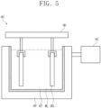
- FIG. 5 schematically shows a strengthening step S300 of providing a mixed melt to strengthen a base glass in the method for manufacturing a window according to an embodiment.
- a strengthening treatment unit HU in which the strengthening step S300 is performed is illustrated as an example.
- the strengthening treatment unit HU of FIG. 5 is schematically illustrated to describe the strengthening step S300, and the form of the strengthening treatment unit HU is not limited to the one shown in FIG 5 .
- the strengthening step S300 may be performed by immersing a base glass BG in a mixed melt ML in the strengthening treatment unit HU.
- the mixed melt ML may contain at least one of the strengthening molten salt and the additives described above.
- the strengthening treatment unit HU may include a tank HT containing the molten mixed melt ML, a heating part HP disposed surrounding the tank HT and applying heat to the mixed melt ML in the tank HT, a driving part HD fixing the base glass BG and vertically moving the base glass BG to immerse the provided base glass BG in the mixed melt ML, and a control part HC controlling the operation of the strengthening treatment unit HU.
- the control part HC may control the temperature of the mixed melt ML contained in the tank HT.
- the control part HC may control the heating part HP to heat the mixed melt ML at a predetermined temperature and keep the temperature of the mixed melt ML at the heated temperature.
- the heating part HP may serve to provide heat to heat the mixed melt ML, or serve as a heat insulator to keep the temperature of the heated mixed melt ML.
- the base glass BG may be disposed to be entirely immersed in the mixed melt ML.
- the base glass BG processed in the mixed melt ML may be one or a plurality of pieces.
- the step S300 of strengthening a base glass may be performed as one strengthening step.
- the strengthening step S300 may be divided into a plurality of steps, and the strengthening step S300 of chemically strengthening a base glass may be performed as a multi-stage strengthening step.
- configurations of the strengthening molten salts used in each strengthening step may be different.
- the embodiment is not limited thereto, and the configurations of the strengthening molten salts used in each strengthening step may be the same or may be different in configurations of some molten salts.
- FIG 6 schematically shows a case in which the strengthening step S300 of strengthening a base glass is performed as a multi-stage strengthening step.
- the strengthening step S300 may include a first strengthening step S310 and a second strengthening step S320 that are sequentially performed.
- the first strengthening step S310 may be a step of strengthening the base glass with providing a strengthening molten salt and an additive to the base glass.
- the second strengthening step S320 may be a step of strengthening the base glass with providing a strengthening molten salt without an additive to strengthen the base glass.
- the first strengthening step S310 may be a step of providing a mixed melt containing a first strengthening molten salt and an additive to the base glass to strengthen the base glass, and for example, the first strengthening molten salt may contain KNO 3 and NaNO 3 .
- the second strengthening step S320 is performed after the first strengthening step S310, and may be a step of providing a melt containing the second strengthening molten salt without an additive to the base glass strengthened in the first strengthening step to further strengthen the base glass.
- the second strengthening molten salt may contain KNO 3 and may not contain NaNO 3 .
- the first strengthening molten salt and the second strengthening molten salt may be different from each other, or when the first strengthening molten salt and the second strengthening molten salt include a plurality of molten salts, at least some of the molten salts may be the same.
- the first strengthening step S310 may be performed at a first temperature and the second strengthening step S320 may be performed at a second temperature. That is, the strengthening step S300 may include the first strengthening step S310 of performing an ion exchange treatment at the first temperature and the second strengthening step S320 of performing an ion exchange treatment at the second temperature.
- the first temperature may be 380 °C to 440 °C
- the second temperature may be 380 °C to 410 °C.
- the first strengthening step S310 may be performed at the first temperature of 380 °C to 440 °C for 2 to 5 hours
- the second strengthening step S320 may be performed at the second temperature of 380 °C to 410 °C for 30 minutes to 2 hours.
- the second temperature of the second strengthening step S320 may be equal to or lower than the first temperature of the first strengthening step S310.
- the first strengthening step S310 may be performed at 420 °C for 2 hours, and then the second strengthening step S320 may be performed at 390 °C for 45 minutes.
- FIG 7 is a flowchart of a method for manufacturing a window according to an embodiment.
- the method for manufacturing a window according to an embodiment may include a step S100 of providing a base glass and a step S300 of strengthening the base glass, and a step S500 of forming a printing layer on the strengthened base glass.
- the printed layer formed in the step S500 of forming a printing layer may be provided on at least one of the upper and lower surfaces of the strengthened base glass.
- the printing layer may be a printing layer BZ providing the bezel area BZA described in FIG 3 .
- the printing layer BZ may be, for example, provided on the lower surface RS ( FIG. 3 ) of the strengthened glass substrate BS ( FIG. 3 ), which is a strengthened base glass.
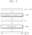
- FIG 8 is a block diagram schematically showing a method for manufacturing a window according to an embodiment.
- each unit performing the step S100 of providing a base glass BG, the strengthening step S300 of strengthening the provided base glass BG, and the printing layer forming step S500 of forming a printing layer on the strengthened glass substrate BS, which correspond to each step in the flowchart of FIG. 7 is indicated as a block.
- the base glass BG is provided to a strengthening treatment unit, and the strengthened glass substrate BS after chemically strengthened in the strengthening treatment unit is transferred to a printing unit. After a printing layer is formed in the printing unit, a window CW including the strengthened glass substrate BS and the printing layer BZ may be provided in the end.
- a cooling step of cooling the strengthened glass substrate BS, a cleaning step of cleaning the strengthened glass substrate BS, etc. may be further included, and accordingly, a cooling unit, a cleaning unit, etc. may be further included between the strengthening treatment unit and the printing unit.
- FIG 9 is a cross-sectional view showing a portion of a window manufactured using the method for manufacturing a window according to an embodiment.
- FIG. 9 may be a cross-sectional view showing a portion of the window of FIG. 3 .
- the compressive stress layer CSL may be formed on a surface of a window manufactured using the method for manufacturing a window according to an embodiment.
- the compressive stress layer CSL may be defined as a layer from the upper surface FS or the lower surface RS of the window to a point at which a compressive stress CS value becomes zero.
- the window manufactured using the method for manufacturing a window according to an embodiment may include the compressive stress layer CSL formed adjacent to the upper surface FS and the lower surface RS, and the surface of the window defining the upper surface FS and the lower surface RS may be provided without damage even after the strengthening step S300.
- the method for manufacturing a window according to an embodiment includes an additive together with a strengthening molten salt in the strengthening step to strengthen the base glass, thereby minimizing a decrease in the compressive stress values of the compressive stress layer on the window surface to provide a window having improved surface durability.
- the window manufactured using the method for manufacturing a window according to an embodiment includes an additive in the strengthening step to strengthen the base glass, thereby minimizing defects on the surface of the manufactured window or voids that may be formed due to vacancies of ions escaping from the inside of the base glass during the strengthening step to exhibit excellent chemical resistance and improved surface strength as well.
- the base glass is strengthened by including additives in the strengthening step, defects on the window surface may be minimized, and a uniform window surface may thus be provided even when a separate post-processing process for improving window surface properties is skipped.
- the printing quality of the printing layer may be well kept.
- FIG 10 is a flowchart showing a conventional method for manufacturing a window.
- the conventional method for manufacturing a window may include a step S100' of providing a base glass, a step S300' of strengthening the base glass, a step S400' of performing a polishing treatment, and a step S500' of forming a printing layer. That is, the conventional method for manufacturing a window is different from the steps of the method for manufacturing a window according to an embodiment in that the conventional method further includes the polishing treatment step S400' after the strengthening step S300'.
- the step S300'of strengthening the base glass may be a step of providing a strengthening molten salt to the base glass to chemically strengthen the base glass. That is, in the step S300'of strengthening the base glass according to the conventional method for manufacturing a window, there is a difference in that when the base glass is chemically strengthened using a strengthening molten salt, the additives suggested in the method for manufacturing a window according to an embodiment are not included.
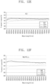
- FIGS. 11 and 12a to 12f are graphs showing results of chemical resistance evaluation for manufactured windows.
- FIG. 11 shows results of chemical resistance evaluation for a window manufactured using the conventional method for manufacturing a window
- FIGS. 12a to 12f show results of chemical resistance evaluation for Example windows manufactured using the method for manufacturing a window according to an embodiment.
- FIG. 12a is a case of a strengthening treatment including Al 2 (SO 4 ) 3 as an additive
- FIGS. 12b , 12c , 12d , 12e, and 12f show results of chemical resistance evaluation for windows strengthened by including Al(NO 3 ) 3 , K 2 SiO 3 , Ca(NO 3 ) 2 , KCl, and Mg(NO 3 ) 2 as an additive, respectively.
- the additives were contained in an amount of 6 wt% in the mixed melt provided to the base glass.
- “REF” is a graph showing transmittance values for each wavelength of windows before acid treatment after being manufactured.
- “EXP1” indicates transmittance values for each wavelength after acid treatment by immersing the manufactured windows in a nitric acid (HNO 3 ) solution having a pH of 1 or less at 50 °C for 2 minutes
- “EXP2” indicates transmittance values for each wavelength after acid treatment by immersing the manufactured windows in a nitric acid (HNO 3 ) solution a pH of 1 or less at 60 °C for 2 minutes.
- the transmittance graphs indicated by "REF”, “EXP1", and “EXP2” overlap each other, and this suggests that a difference in transmittance is minute or similar to the conditions displayed by the overlapping graphs.
- the strengthening step was performed as a multi-stage strengthening step.
- the first strengthening step included KNO 3 and NaNO 3- as a strengthening molten salt and was performed at 420 °C for 2 hours
- the second strengthening step included KNO 3 as a strengthening molten salt and was performed at 390 °C for 45 minutes.
- additives were not included in the strengthening step
- additives each were included in the first strengthening step.
- the window transmittance after the acid treatment increased compared to the window transmittance before the acid treatment. This is believed to be due to an increase in the window transmittance when some chemical components were eluted from the window surface during the chemical resistance evaluation called acid treatment, indicating that the physical properties of the window surface changed after the acid treatment.
- the strengthened window has excellent chemical resistance. That is, it is seen that when the base glass is strengthened by including Al 2 (SO 4 ) 3 , Al(NO 3 ) 3 , or K 2 SiO 3 as an additive together with the strengthening molten salt during the strengthening step in the method for manufacturing a window according to an embodiment, good surface compressive stress values and excellent surface chemical resistance are shown.
- FIG 13 is a perspective view illustrating a window CW-a manufactured using the method for manufacturing a window according to an embodiment of the present invention.
- FIGS. 14a and 14b are perspective views illustrating windows CW-b1 and CW-b2 manufactured using the method for manufacturing a window according to an embodiment of the present invention.
- FIGS. 13 and 14a to 14b differences will be mainly described except for the description overlapping the one described in FIGS. 1 to 10 .
- the window CW-a may include a bending portion BA bent around a bending axis BX.
- the window CW-a may include a flat portion FA and a bending portion BA.
- the bending axis BX may extend along the second directional axis DR2 and may be provided on a rear surface of the window CW-a.
- the flat portion FA may be a portion parallel to a plane defined by the first and second directional axes DR1 and DR2.
- the bending portion BA may be a curved portion adjacent to the flat portion FA and having a curved shape.
- the bending portion BA is a portion adjacent to both sides of the flat portion FA, and may be a portion bent downwards from the flat portion FA.
- the embodiment is not limited thereto, and the bending portion BA may be disposed adjacent to only one side of the flat portion FA, or may be disposed adjacent to all four sides of the flat portion FA on a plane.
- the window CW-a includes a base glass strengthened in a mixed melt containing an additive together with a strengthening molten salt, and has good surface compressive stress values and excellent surface chemical resistance without a separate post-processing step after the strengthening step.
- the windows CW-b1 and CW-b2 manufactured the method for manufacturing a window according to an embodiment may be folded or unfolded around a folding axis FX as illustrated in FIGS. 14a and 14b .
- the window CW-b1 in an unfolded state is shown in FIG 14a and the window CW-b2 in a folded state is shown in FIG 14b .
- the folding axis FX may extend along the first directional axis DR1 and may be defined on an upper surface FS of the window CW-b1. That is, in FIGS. 14a to 14b , an in-folding window in which a lower surface RS of the window CW-b2 is exposed to the outside when being folded is illustrated, but the embodiment is not limited thereto.
- the window according to an embodiment may be a window in which the folding axis FX is defined below the lower surface RS of the window CW-b1 and is out-folded unlike the one shown in FIGS. 14a and 14b .
- the windows CW-b1 and CW-b2 that are modifiable in shape during use may also be manufactured using the method for manufacturing a window according to an embodiment, and go through the strengthening step 5300 by including an additive together with the strengthening molten salt in the strengthening step to have good surface compressive stress values and excellent surface chemical resistance without a separate post-processing step after the strengthening step.
- the window CW-a having the bending portion BA manufactured using the method for manufacturing a window according to an embodiment or the windows CW-b1 and CW-b2 that are modifiable in shape may exhibit good surface compressive stress values and excellent durability even without the polishing treatment step after the strengthening step, and may thus be applied to various electronic devices.
- the method for manufacturing a window according to an embodiment may provide excellent surface chemical resistance and good surface compressive stress characteristics by strengthening a base glass using a mixed melt containing an additive together with a strengthening molten salt in the strengthening step.
- the method for manufacturing a window according to an embodiment provides good surface compressive stress characteristics and excellent surface durability even without the polishing treatment step provided after the strengthening step in order to remove surface defects of the strengthened glass substrate, thereby showing improved processability.
- the method for manufacturing a window according to an embodiment provides good surface characteristics by strengthening the base glass using a mixed melt containing an additive together with a strengthening molten salt in the strengthening step, and provides enhanced printing quality provided on the surface of the strengthened base glass and increased durability of a printed layer to the surface of the base glass.
- the present invention relates to a method for manufacturing a window, which provides a window used as cover glass of an electronic device and having excellent surface durability, and thus has high industrial applicability.
Landscapes
- Chemical & Material Sciences (AREA)
- Life Sciences & Earth Sciences (AREA)
- Engineering & Computer Science (AREA)
- Chemical Kinetics & Catalysis (AREA)
- General Chemical & Material Sciences (AREA)
- Geochemistry & Mineralogy (AREA)
- Materials Engineering (AREA)
- Organic Chemistry (AREA)
- Ceramic Engineering (AREA)
- Surface Treatment Of Glass (AREA)
- Glass Compositions (AREA)
- Devices For Indicating Variable Information By Combining Individual Elements (AREA)
Claims (14)
- Procédé de fabrication d'une fenêtre utilisée comme verre de couverture d'un dispositif électronique (CW), le procédé comprenant les étapes suivantes :une étape (S100) de fourniture d'un verre de base (BG) ; etune étape (S300) de renforcement du verre de base (BG) en fournissant une matière fondue mixte au verre de base, et la matière fondue mixte (ML) contenant un sel fondu de renforcement et un additif,dans lequel le sel fondu de renforcement est un sel mixte contenant deux ions ou plus choisis dans le groupe consistant en Li+, Na+, K+, Rb+ et Cs+, ou un sel unique contenant un ion quelconque choisi dans le groupe consistant en Li+, Na+, K+, Rb+ et Cs+,dans lequel l'additif contient au moins un parmi Al2(SO4)3, Al(NO3)3, K2SiO3, Na2SiO3, KCI, Ca(NO3)2 et Mg(NO3)2, etdans lequel l'additif est contenu dans une quantité de plus de 0 % en poids à 10 % en poids par rapport au poids total de la matière fondue mixte (ML).
- Procédé selon la revendication 1, dans lequel l'additif est Al2(SO4)3 ou Al(NO3)3.
- Procédé selon la revendication 1, dans lequel le verre de base (BG) contient du SiO2, de l'Al2O3 et du Li2O.
- Procédé selon la revendication 3, dans lequel le verre de base (BG) contient en outre du P2O5.
- Procédé selon la revendication 3, dans lequel le verre de base (BG) contient :du SiO2 dans une quantité de 50 % en poids à 80 % en poids ;de l'Al2O3 dans une quantité de 10 % en poids à 30 % en poids ; etdu Li2O dans une quantité de 3 % en poids à 20 % en poids.
- Procédé selon la revendication 1, dans lequel le verre de base (BG) contient du SiO2, de I'Al2O3, et du P2O5, et ne contient pas de Li2O.
- Procédé selon la revendication 1, dans lequel l'étape de renforcement (300) comprend :une première étape de renforcement consistant à fournir un premier sel fondu de renforcement et l'additif pour renforcer le verre de base (BG) ; etune seconde étape de renforcement consistant à fournir un second sel fondu de renforcement sans l'additif pour renforcer le verre de base (BG).
- Procédé selon la revendication 7, dans lequel :la première étape de renforcement est effectuée à une première température ; etla seconde étape de renforcement est effectuée à une seconde température inférieure à la première température.
- Procédé selon la revendication 7, dans lequel :la première étape de renforcement est effectuée à 380 °C jusqu'à 440 °C ; etla seconde étape de renforcement est effectuée à 380 °C jusqu'à 410 °C.
- Procédé selon la revendication 7, dans lequel :le premier sel fondu de renforcement contient du KNO3 et du NaNO3 ; etle second sel fondu de renforcement contient du KNO3 et ne contient pas de NaNO3.
- Procédé selon la revendication 1, comprenant en outre une étape de formation d'une couche d'impression sur au moins une parmi une surface supérieure et une surface inférieure du verre de base soumis à l'étape (S300) de renforcement.
- Procédé selon la revendication 1, dans lequel :le sel fondu de renforcement contient au moins un parmi : KNO3 et NaNO3 ; etl'additif contient de l'Al2(SO4)3 ou de l'Al(NO3)3.
- Procédé selon la revendication 1, dans lequel :la matière fondue mixte (ML) contient au moins un parmi : Al2(SO4)3 et Al(NO3)3, KNO3 et NaNO3 ; etla matière fondue contient du KNO3.
- Procédé selon la revendication 1, comprenant en outre une étape de formation d'une couche d'impression sur au moins une parmi une surface supérieure et une surface inférieure du verre de base (BG) renforcé après la seconde étape de renforcement,
dans lequel, entre la seconde étape de renforcement et l'étape de formation d'une couche d'impression, une étape de traitement par polissage (S400) consistant à polir au moins une surface du verre de base (BG) n'est pas incluse.
Applications Claiming Priority (2)
| Application Number | Priority Date | Filing Date | Title |
|---|---|---|---|
| KR1020190000995A KR102758699B1 (ko) | 2019-01-04 | 2019-01-04 | 윈도우 제조 방법 |
| PCT/KR2019/004926 WO2020141656A1 (fr) | 2019-01-04 | 2019-04-23 | Procédé de production d'une fenêtre |
Publications (3)
| Publication Number | Publication Date |
|---|---|
| EP3907201A1 EP3907201A1 (fr) | 2021-11-10 |
| EP3907201A4 EP3907201A4 (fr) | 2022-11-02 |
| EP3907201B1 true EP3907201B1 (fr) | 2024-08-14 |
Family
ID=71407201
Family Applications (1)
| Application Number | Title | Priority Date | Filing Date |
|---|---|---|---|
| EP19906907.1A Active EP3907201B1 (fr) | 2019-01-04 | 2019-04-23 | Procédé de production d'une fenêtre servant de verre de couverture d'un dispositif électronique |
Country Status (6)
| Country | Link |
|---|---|
| US (1) | US20220017411A1 (fr) |
| EP (1) | EP3907201B1 (fr) |
| JP (1) | JP7350073B2 (fr) |
| KR (1) | KR102758699B1 (fr) |
| CN (1) | CN113272264A (fr) |
| WO (1) | WO2020141656A1 (fr) |
Families Citing this family (2)
| Publication number | Priority date | Publication date | Assignee | Title |
|---|---|---|---|---|
| KR20220163550A (ko) | 2021-06-02 | 2022-12-12 | 삼성디스플레이 주식회사 | 유리 강화용 용융염 및 이를 이용한 유리 강화 방법 |
| CN115745426B (zh) * | 2022-11-03 | 2023-07-07 | 青岛中兴通轨道交通科技有限公司 | 一种锂铝硅玻璃的强化方法 |
Citations (1)
| Publication number | Priority date | Publication date | Assignee | Title |
|---|---|---|---|---|
| US20090277222A1 (en) * | 2006-09-29 | 2009-11-12 | Hoya Corporation | Method for producing glass substrate for magnetic disk and method for producing magnetic disk |
Family Cites Families (27)
| Publication number | Priority date | Publication date | Assignee | Title |
|---|---|---|---|---|
| JP3702360B2 (ja) * | 2001-01-04 | 2005-10-05 | 日本板硝子株式会社 | 化学強化用のガラス素板の製造方法 |
| JP5094303B2 (ja) | 2006-09-29 | 2012-12-12 | Hoya株式会社 | 磁気ディスク用ガラス基板および磁気ディスクの製造方法 |
| JP5683971B2 (ja) | 2010-03-19 | 2015-03-11 | 石塚硝子株式会社 | 化学強化用ガラス組成物及び化学強化ガラス材 |
| KR20120038079A (ko) * | 2010-10-13 | 2012-04-23 | 주식회사 에스엘 | 디스플레이용 강화유리 제조방법 및 그 강화유리 |
| JP5975023B2 (ja) * | 2011-04-15 | 2016-08-23 | 旭硝子株式会社 | 表面処理されたガラス基体の製造方法 |
| WO2013035840A1 (fr) * | 2011-09-09 | 2013-03-14 | Hoya株式会社 | Procédé de production d'un verre protecteur pour appareil portatif |
| US20130133745A1 (en) | 2011-11-30 | 2013-05-30 | James Patrick Hamilton | Incorporation of alkaline earth ions into alkali-containing glass surfaces to inhibit alkali egress |
| JP5655980B2 (ja) * | 2012-09-18 | 2015-01-21 | 旭硝子株式会社 | ガラス化学強化用溶融塩の再生方法及び強化ガラスの製造方法 |
| DE112014003344T5 (de) | 2013-07-19 | 2016-03-31 | Asahi Glass Company, Limited | Chemisch Gehärtetes Glas |
| DE102014013527A1 (de) * | 2014-09-12 | 2016-03-17 | Schott Ag | Verfahren zur Herstellung eines beschichteten, chemisch vorgespannten Glassubstrats mit Antifingerprint-Eigenschaften sowie das hergestellte Glassubstrat |
| DE102014013550A1 (de) * | 2014-09-12 | 2016-03-31 | Schott Ag | Beschichtetes chemisch vorgespanntes flexibles dünnes Glas |
| WO2016137916A2 (fr) * | 2015-02-27 | 2016-09-01 | Corning Incorporated | Procédé de renforcement chimique à basse température pour le verre |
| WO2016149860A1 (fr) * | 2015-03-20 | 2016-09-29 | Schott Glass Technologies (Suzhou) Co. Ltd. | Objet en verre mince présentant une couche de surface ayant subi un échange d'ions de manière non uniforme et procédé de fabrication d'un tel objet en verre mince |
| US10579106B2 (en) * | 2015-07-21 | 2020-03-03 | Corning Incorporated | Glass articles exhibiting improved fracture performance |
| WO2017094727A1 (fr) * | 2015-12-02 | 2017-06-08 | 旭硝子株式会社 | Procédé de fabrication de verre |
| KR102610962B1 (ko) * | 2016-08-02 | 2023-12-08 | 삼성디스플레이 주식회사 | 유리 기판의 처리 방법 |
| KR102710638B1 (ko) * | 2017-02-02 | 2024-09-27 | 코닝 인코포레이티드 | 유리 표면 가까이에 변경된 k2o 프로파일을 갖는 리튬 함유 유리 또는 유리 세라믹 물품 |
| US11691911B2 (en) | 2017-04-13 | 2023-07-04 | Samsung Display Co., Ltd. | Reinforced window member and method of manufacturing the same |
| CN109206021B (zh) * | 2017-06-29 | 2020-11-03 | 重庆鑫景特种玻璃有限公司 | 用于玻璃强化的盐浴及其制备方法、强化玻璃和原料玻璃 |
| JP7310791B2 (ja) * | 2018-02-16 | 2023-07-19 | Agc株式会社 | カバーガラス、およびインセル型液晶表示装置 |
| CN108658453A (zh) * | 2018-05-28 | 2018-10-16 | 广东金刚玻璃科技股份有限公司 | 一种抗菌型硅铝酸盐玻璃及其制备方法 |
| JP7344909B2 (ja) * | 2018-05-31 | 2023-09-14 | コーニング インコーポレイテッド | リチウム含有ガラスの逆イオン交換処理 |
| WO2020008901A1 (fr) * | 2018-07-03 | 2020-01-09 | Agc株式会社 | Verre renforcé chimiquement et son procédé de fabrication |
| WO2020060971A1 (fr) * | 2018-09-20 | 2020-03-26 | Corning Incorporated | Procédé d'échange d'ions inverse destiné un verre contenant du lithium |
| CN119638201A (zh) * | 2018-11-13 | 2025-03-18 | 康宁股份有限公司 | 化学强化的焦硅酸锂-透锂长石玻璃陶瓷 |
| KR20220163550A (ko) * | 2021-06-02 | 2022-12-12 | 삼성디스플레이 주식회사 | 유리 강화용 용융염 및 이를 이용한 유리 강화 방법 |
| KR20230143219A (ko) * | 2022-04-01 | 2023-10-12 | 삼성디스플레이 주식회사 | 윈도우 제조 방법, 그에 따라 제조된 윈도우, 및 윈도우를 포함하는 표시 장치 |
-
2019
- 2019-01-04 KR KR1020190000995A patent/KR102758699B1/ko active Active
- 2019-04-23 CN CN201980087758.4A patent/CN113272264A/zh active Pending
- 2019-04-23 US US17/298,505 patent/US20220017411A1/en active Pending
- 2019-04-23 EP EP19906907.1A patent/EP3907201B1/fr active Active
- 2019-04-23 WO PCT/KR2019/004926 patent/WO2020141656A1/fr not_active Ceased
- 2019-04-23 JP JP2021538986A patent/JP7350073B2/ja active Active
Patent Citations (1)
| Publication number | Priority date | Publication date | Assignee | Title |
|---|---|---|---|---|
| US20090277222A1 (en) * | 2006-09-29 | 2009-11-12 | Hoya Corporation | Method for producing glass substrate for magnetic disk and method for producing magnetic disk |
Also Published As
| Publication number | Publication date |
|---|---|
| TW202039397A (zh) | 2020-11-01 |
| JP2022517066A (ja) | 2022-03-04 |
| JP7350073B2 (ja) | 2023-09-25 |
| KR102758699B1 (ko) | 2025-01-23 |
| EP3907201A4 (fr) | 2022-11-02 |
| CN113272264A (zh) | 2021-08-17 |
| WO2020141656A1 (fr) | 2020-07-09 |
| US20220017411A1 (en) | 2022-01-20 |
| EP3907201A1 (fr) | 2021-11-10 |
| KR20200085387A (ko) | 2020-07-15 |
Similar Documents
| Publication | Publication Date | Title |
|---|---|---|
| US12215054B2 (en) | Window and method of manufacturing the same | |
| EP3907201A1 (fr) | Procédé de production d'une fenêtre | |
| KR20140074329A (ko) | 도전 시트, 터치 패널, 표시 장치 | |
| CN103781739A (zh) | 便携设备用保护玻璃的制造方法 | |
| KR102657561B1 (ko) | 유리 기판 및 유리 기판의 제조 방법 | |
| KR20140085364A (ko) | 터치 패널 형성용 강화 유리 기판의 제조 방법 | |
| TWI904080B (zh) | 窗口及其製造方法 | |
| US20240101472A1 (en) | Method of manufacturing window, window manufactured thereby, and display device including the window | |
| JP7854779B2 (ja) | ウィンドウ製造方法 | |
| US20230312411A1 (en) | Method of manufacturing window, window manufactured by the method of manufacturing window, and display device including the window | |
| US20220348492A1 (en) | Method of manufacturing window and window manufactured by the same | |
| US20240343640A1 (en) | Window, display device including the window, and method of manufacturing the window | |
| KR20150008246A (ko) | 보호층의 제거 방법 | |
| US20240182360A1 (en) | Window and method of manufacturing the same | |
| US12441086B2 (en) | Method of manufacturing window | |
| KR20250078709A (ko) | 윈도우, 표시장치 및 윈도우의 제조방법 | |
| KR20240110165A (ko) | 윈도우, 이를 포함하는 표시 장치 및 윈도우의 제조방법 |
Legal Events
| Date | Code | Title | Description |
|---|---|---|---|
| STAA | Information on the status of an ep patent application or granted ep patent |
Free format text: STATUS: THE INTERNATIONAL PUBLICATION HAS BEEN MADE |
|
| PUAI | Public reference made under article 153(3) epc to a published international application that has entered the european phase |
Free format text: ORIGINAL CODE: 0009012 |
|
| STAA | Information on the status of an ep patent application or granted ep patent |
Free format text: STATUS: REQUEST FOR EXAMINATION WAS MADE |
|
| 17P | Request for examination filed |
Effective date: 20210629 |
|
| AK | Designated contracting states |
Kind code of ref document: A1 Designated state(s): AL AT BE BG CH CY CZ DE DK EE ES FI FR GB GR HR HU IE IS IT LI LT LU LV MC MK MT NL NO PL PT RO RS SE SI SK SM TR |
|
| DAV | Request for validation of the european patent (deleted) | ||
| DAX | Request for extension of the european patent (deleted) | ||
| A4 | Supplementary search report drawn up and despatched |
Effective date: 20220930 |
|
| RIC1 | Information provided on ipc code assigned before grant |
Ipc: C03C 3/097 20060101ALI20220927BHEP Ipc: C03C 3/083 20060101ALI20220927BHEP Ipc: C03C 21/00 20060101AFI20220927BHEP |
|
| P01 | Opt-out of the competence of the unified patent court (upc) registered |
Effective date: 20230516 |
|
| GRAP | Despatch of communication of intention to grant a patent |
Free format text: ORIGINAL CODE: EPIDOSNIGR1 |
|
| STAA | Information on the status of an ep patent application or granted ep patent |
Free format text: STATUS: GRANT OF PATENT IS INTENDED |
|
| INTG | Intention to grant announced |
Effective date: 20240311 |
|
| GRAS | Grant fee paid |
Free format text: ORIGINAL CODE: EPIDOSNIGR3 |
|
| GRAA | (expected) grant |
Free format text: ORIGINAL CODE: 0009210 |
|
| STAA | Information on the status of an ep patent application or granted ep patent |
Free format text: STATUS: THE PATENT HAS BEEN GRANTED |
|
| AK | Designated contracting states |
Kind code of ref document: B1 Designated state(s): AL AT BE BG CH CY CZ DE DK EE ES FI FR GB GR HR HU IE IS IT LI LT LU LV MC MK MT NL NO PL PT RO RS SE SI SK SM TR |
|
| REG | Reference to a national code |
Ref country code: GB Ref legal event code: FG4D |
|
| REG | Reference to a national code |
Ref country code: CH Ref legal event code: EP |
|
| REG | Reference to a national code |
Ref country code: DE Ref legal event code: R096 Ref document number: 602019057184 Country of ref document: DE |
|
| REG | Reference to a national code |
Ref country code: IE Ref legal event code: FG4D |
|
| REG | Reference to a national code |
Ref country code: NL Ref legal event code: FP |
|
| REG | Reference to a national code |
Ref country code: LT Ref legal event code: MG9D |
|
| PG25 | Lapsed in a contracting state [announced via postgrant information from national office to epo] |
Ref country code: NO Free format text: LAPSE BECAUSE OF FAILURE TO SUBMIT A TRANSLATION OF THE DESCRIPTION OR TO PAY THE FEE WITHIN THE PRESCRIBED TIME-LIMIT Effective date: 20241114 |
|
| REG | Reference to a national code |
Ref country code: AT Ref legal event code: MK05 Ref document number: 1713199 Country of ref document: AT Kind code of ref document: T Effective date: 20240814 |
|
| PG25 | Lapsed in a contracting state [announced via postgrant information from national office to epo] |
Ref country code: FI Free format text: LAPSE BECAUSE OF FAILURE TO SUBMIT A TRANSLATION OF THE DESCRIPTION OR TO PAY THE FEE WITHIN THE PRESCRIBED TIME-LIMIT Effective date: 20240814 Ref country code: PT Free format text: LAPSE BECAUSE OF FAILURE TO SUBMIT A TRANSLATION OF THE DESCRIPTION OR TO PAY THE FEE WITHIN THE PRESCRIBED TIME-LIMIT Effective date: 20241216 Ref country code: GR Free format text: LAPSE BECAUSE OF FAILURE TO SUBMIT A TRANSLATION OF THE DESCRIPTION OR TO PAY THE FEE WITHIN THE PRESCRIBED TIME-LIMIT Effective date: 20241115 Ref country code: PL Free format text: LAPSE BECAUSE OF FAILURE TO SUBMIT A TRANSLATION OF THE DESCRIPTION OR TO PAY THE FEE WITHIN THE PRESCRIBED TIME-LIMIT Effective date: 20240814 |
|
| PG25 | Lapsed in a contracting state [announced via postgrant information from national office to epo] |
Ref country code: BG Free format text: LAPSE BECAUSE OF FAILURE TO SUBMIT A TRANSLATION OF THE DESCRIPTION OR TO PAY THE FEE WITHIN THE PRESCRIBED TIME-LIMIT Effective date: 20240814 |
|
| PG25 | Lapsed in a contracting state [announced via postgrant information from national office to epo] |
Ref country code: LV Free format text: LAPSE BECAUSE OF FAILURE TO SUBMIT A TRANSLATION OF THE DESCRIPTION OR TO PAY THE FEE WITHIN THE PRESCRIBED TIME-LIMIT Effective date: 20240814 |
|
| PG25 | Lapsed in a contracting state [announced via postgrant information from national office to epo] |
Ref country code: AT Free format text: LAPSE BECAUSE OF FAILURE TO SUBMIT A TRANSLATION OF THE DESCRIPTION OR TO PAY THE FEE WITHIN THE PRESCRIBED TIME-LIMIT Effective date: 20240814 Ref country code: IS Free format text: LAPSE BECAUSE OF FAILURE TO SUBMIT A TRANSLATION OF THE DESCRIPTION OR TO PAY THE FEE WITHIN THE PRESCRIBED TIME-LIMIT Effective date: 20241214 |
|
| PG25 | Lapsed in a contracting state [announced via postgrant information from national office to epo] |
Ref country code: HR Free format text: LAPSE BECAUSE OF FAILURE TO SUBMIT A TRANSLATION OF THE DESCRIPTION OR TO PAY THE FEE WITHIN THE PRESCRIBED TIME-LIMIT Effective date: 20240814 |
|
| PG25 | Lapsed in a contracting state [announced via postgrant information from national office to epo] |
Ref country code: ES Free format text: LAPSE BECAUSE OF FAILURE TO SUBMIT A TRANSLATION OF THE DESCRIPTION OR TO PAY THE FEE WITHIN THE PRESCRIBED TIME-LIMIT Effective date: 20240814 Ref country code: RS Free format text: LAPSE BECAUSE OF FAILURE TO SUBMIT A TRANSLATION OF THE DESCRIPTION OR TO PAY THE FEE WITHIN THE PRESCRIBED TIME-LIMIT Effective date: 20241114 |
|
| PG25 | Lapsed in a contracting state [announced via postgrant information from national office to epo] |
Ref country code: RS Free format text: LAPSE BECAUSE OF FAILURE TO SUBMIT A TRANSLATION OF THE DESCRIPTION OR TO PAY THE FEE WITHIN THE PRESCRIBED TIME-LIMIT Effective date: 20241114 Ref country code: PT Free format text: LAPSE BECAUSE OF FAILURE TO SUBMIT A TRANSLATION OF THE DESCRIPTION OR TO PAY THE FEE WITHIN THE PRESCRIBED TIME-LIMIT Effective date: 20241216 Ref country code: PL Free format text: LAPSE BECAUSE OF FAILURE TO SUBMIT A TRANSLATION OF THE DESCRIPTION OR TO PAY THE FEE WITHIN THE PRESCRIBED TIME-LIMIT Effective date: 20240814 Ref country code: NO Free format text: LAPSE BECAUSE OF FAILURE TO SUBMIT A TRANSLATION OF THE DESCRIPTION OR TO PAY THE FEE WITHIN THE PRESCRIBED TIME-LIMIT Effective date: 20241114 Ref country code: LV Free format text: LAPSE BECAUSE OF FAILURE TO SUBMIT A TRANSLATION OF THE DESCRIPTION OR TO PAY THE FEE WITHIN THE PRESCRIBED TIME-LIMIT Effective date: 20240814 Ref country code: IS Free format text: LAPSE BECAUSE OF FAILURE TO SUBMIT A TRANSLATION OF THE DESCRIPTION OR TO PAY THE FEE WITHIN THE PRESCRIBED TIME-LIMIT Effective date: 20241214 Ref country code: HR Free format text: LAPSE BECAUSE OF FAILURE TO SUBMIT A TRANSLATION OF THE DESCRIPTION OR TO PAY THE FEE WITHIN THE PRESCRIBED TIME-LIMIT Effective date: 20240814 Ref country code: GR Free format text: LAPSE BECAUSE OF FAILURE TO SUBMIT A TRANSLATION OF THE DESCRIPTION OR TO PAY THE FEE WITHIN THE PRESCRIBED TIME-LIMIT Effective date: 20241115 Ref country code: FI Free format text: LAPSE BECAUSE OF FAILURE TO SUBMIT A TRANSLATION OF THE DESCRIPTION OR TO PAY THE FEE WITHIN THE PRESCRIBED TIME-LIMIT Effective date: 20240814 Ref country code: ES Free format text: LAPSE BECAUSE OF FAILURE TO SUBMIT A TRANSLATION OF THE DESCRIPTION OR TO PAY THE FEE WITHIN THE PRESCRIBED TIME-LIMIT Effective date: 20240814 Ref country code: BG Free format text: LAPSE BECAUSE OF FAILURE TO SUBMIT A TRANSLATION OF THE DESCRIPTION OR TO PAY THE FEE WITHIN THE PRESCRIBED TIME-LIMIT Effective date: 20240814 Ref country code: AT Free format text: LAPSE BECAUSE OF FAILURE TO SUBMIT A TRANSLATION OF THE DESCRIPTION OR TO PAY THE FEE WITHIN THE PRESCRIBED TIME-LIMIT Effective date: 20240814 |
|
| PG25 | Lapsed in a contracting state [announced via postgrant information from national office to epo] |
Ref country code: RO Free format text: LAPSE BECAUSE OF FAILURE TO SUBMIT A TRANSLATION OF THE DESCRIPTION OR TO PAY THE FEE WITHIN THE PRESCRIBED TIME-LIMIT Effective date: 20240814 Ref country code: DK Free format text: LAPSE BECAUSE OF FAILURE TO SUBMIT A TRANSLATION OF THE DESCRIPTION OR TO PAY THE FEE WITHIN THE PRESCRIBED TIME-LIMIT Effective date: 20240814 Ref country code: SM Free format text: LAPSE BECAUSE OF FAILURE TO SUBMIT A TRANSLATION OF THE DESCRIPTION OR TO PAY THE FEE WITHIN THE PRESCRIBED TIME-LIMIT Effective date: 20240814 |
|
| PG25 | Lapsed in a contracting state [announced via postgrant information from national office to epo] |
Ref country code: EE Free format text: LAPSE BECAUSE OF FAILURE TO SUBMIT A TRANSLATION OF THE DESCRIPTION OR TO PAY THE FEE WITHIN THE PRESCRIBED TIME-LIMIT Effective date: 20240814 |
|
| PG25 | Lapsed in a contracting state [announced via postgrant information from national office to epo] |
Ref country code: CZ Free format text: LAPSE BECAUSE OF FAILURE TO SUBMIT A TRANSLATION OF THE DESCRIPTION OR TO PAY THE FEE WITHIN THE PRESCRIBED TIME-LIMIT Effective date: 20240814 |
|
| PG25 | Lapsed in a contracting state [announced via postgrant information from national office to epo] |
Ref country code: IT Free format text: LAPSE BECAUSE OF FAILURE TO SUBMIT A TRANSLATION OF THE DESCRIPTION OR TO PAY THE FEE WITHIN THE PRESCRIBED TIME-LIMIT Effective date: 20240814 Ref country code: SK Free format text: LAPSE BECAUSE OF FAILURE TO SUBMIT A TRANSLATION OF THE DESCRIPTION OR TO PAY THE FEE WITHIN THE PRESCRIBED TIME-LIMIT Effective date: 20240814 |
|
| REG | Reference to a national code |
Ref country code: DE Ref legal event code: R097 Ref document number: 602019057184 Country of ref document: DE |
|
| PLBE | No opposition filed within time limit |
Free format text: ORIGINAL CODE: 0009261 |
|
| STAA | Information on the status of an ep patent application or granted ep patent |
Free format text: STATUS: NO OPPOSITION FILED WITHIN TIME LIMIT |
|
| PGFP | Annual fee paid to national office [announced via postgrant information from national office to epo] |
Ref country code: DE Payment date: 20250320 Year of fee payment: 7 |
|
| 26N | No opposition filed |
Effective date: 20250515 |
|
| PG25 | Lapsed in a contracting state [announced via postgrant information from national office to epo] |
Ref country code: SE Free format text: LAPSE BECAUSE OF FAILURE TO SUBMIT A TRANSLATION OF THE DESCRIPTION OR TO PAY THE FEE WITHIN THE PRESCRIBED TIME-LIMIT Effective date: 20240814 |
|
| REG | Reference to a national code |
Ref country code: CH Ref legal event code: H13 Free format text: ST27 STATUS EVENT CODE: U-0-0-H10-H13 (AS PROVIDED BY THE NATIONAL OFFICE) Effective date: 20251125 |
|
| PG25 | Lapsed in a contracting state [announced via postgrant information from national office to epo] |
Ref country code: LU Free format text: LAPSE BECAUSE OF NON-PAYMENT OF DUE FEES Effective date: 20250423 |
|
| PG25 | Lapsed in a contracting state [announced via postgrant information from national office to epo] |
Ref country code: MC Free format text: LAPSE BECAUSE OF FAILURE TO SUBMIT A TRANSLATION OF THE DESCRIPTION OR TO PAY THE FEE WITHIN THE PRESCRIBED TIME-LIMIT Effective date: 20240814 |
|
| REG | Reference to a national code |
Ref country code: BE Ref legal event code: MM Effective date: 20250430 |
|
| PG25 | Lapsed in a contracting state [announced via postgrant information from national office to epo] |
Ref country code: BE Free format text: LAPSE BECAUSE OF NON-PAYMENT OF DUE FEES Effective date: 20250430 |
|
| PG25 | Lapsed in a contracting state [announced via postgrant information from national office to epo] |
Ref country code: CH Free format text: LAPSE BECAUSE OF NON-PAYMENT OF DUE FEES Effective date: 20250430 |
|
| PGFP | Annual fee paid to national office [announced via postgrant information from national office to epo] |
Ref country code: GB Payment date: 20260324 Year of fee payment: 8 |
|
| PG25 | Lapsed in a contracting state [announced via postgrant information from national office to epo] |
Ref country code: IE Free format text: LAPSE BECAUSE OF NON-PAYMENT OF DUE FEES Effective date: 20250423 |
|
| PGFP | Annual fee paid to national office [announced via postgrant information from national office to epo] |
Ref country code: NL Payment date: 20260324 Year of fee payment: 8 |
|
| PGFP | Annual fee paid to national office [announced via postgrant information from national office to epo] |
Ref country code: FR Payment date: 20260323 Year of fee payment: 8 |